EP4032845A1 - Wall climbing elevator - Google Patents
Wall climbing elevator Download PDFInfo
- Publication number
- EP4032845A1 EP4032845A1 EP21205915.8A EP21205915A EP4032845A1 EP 4032845 A1 EP4032845 A1 EP 4032845A1 EP 21205915 A EP21205915 A EP 21205915A EP 4032845 A1 EP4032845 A1 EP 4032845A1
- Authority
- EP
- European Patent Office
- Prior art keywords
- drive members
- elevator car
- elevator
- walls
- guiding surfaces
- Prior art date
- Legal status (The legal status is an assumption and is not a legal conclusion. Google has not performed a legal analysis and makes no representation as to the accuracy of the status listed.)
- Granted
Links
Images


Classifications
-
- B—PERFORMING OPERATIONS; TRANSPORTING
- B66—HOISTING; LIFTING; HAULING
- B66B—ELEVATORS; ESCALATORS OR MOVING WALKWAYS
- B66B9/00—Kinds or types of lifts in, or associated with, buildings or other structures
- B66B9/02—Kinds or types of lifts in, or associated with, buildings or other structures actuated mechanically otherwise than by rope or cable
-
- B—PERFORMING OPERATIONS; TRANSPORTING
- B66—HOISTING; LIFTING; HAULING
- B66B—ELEVATORS; ESCALATORS OR MOVING WALKWAYS
- B66B1/00—Control systems of elevators in general
- B66B1/24—Control systems with regulation, i.e. with retroactive action, for influencing travelling speed, acceleration, or deceleration
- B66B1/28—Control systems with regulation, i.e. with retroactive action, for influencing travelling speed, acceleration, or deceleration electrical
- B66B1/30—Control systems with regulation, i.e. with retroactive action, for influencing travelling speed, acceleration, or deceleration electrical effective on driving gear, e.g. acting on power electronics, on inverter or rectifier controlled motor
-
- B—PERFORMING OPERATIONS; TRANSPORTING
- B66—HOISTING; LIFTING; HAULING
- B66B—ELEVATORS; ESCALATORS OR MOVING WALKWAYS
- B66B11/00—Main component parts of lifts in, or associated with, buildings or other structures
- B66B11/0005—Constructional features of hoistways
-
- B—PERFORMING OPERATIONS; TRANSPORTING
- B66—HOISTING; LIFTING; HAULING
- B66B—ELEVATORS; ESCALATORS OR MOVING WALKWAYS
- B66B11/00—Main component parts of lifts in, or associated with, buildings or other structures
- B66B11/0035—Arrangement of driving gear, e.g. location or support
- B66B11/0045—Arrangement of driving gear, e.g. location or support in the hoistway
- B66B11/005—Arrangement of driving gear, e.g. location or support in the hoistway on the car
-
- B—PERFORMING OPERATIONS; TRANSPORTING
- B66—HOISTING; LIFTING; HAULING
- B66B—ELEVATORS; ESCALATORS OR MOVING WALKWAYS
- B66B11/00—Main component parts of lifts in, or associated with, buildings or other structures
- B66B11/04—Driving gear ; Details thereof, e.g. seals
- B66B11/043—Driving gear ; Details thereof, e.g. seals actuated by rotating motor; Details, e.g. ventilation
-
- B—PERFORMING OPERATIONS; TRANSPORTING
- B66—HOISTING; LIFTING; HAULING
- B66B—ELEVATORS; ESCALATORS OR MOVING WALKWAYS
- B66B7/00—Other common features of elevators
- B66B7/02—Guideways; Guides
- B66B7/022—Guideways; Guides with a special shape
-
- B—PERFORMING OPERATIONS; TRANSPORTING
- B66—HOISTING; LIFTING; HAULING
- B66B—ELEVATORS; ESCALATORS OR MOVING WALKWAYS
- B66B7/00—Other common features of elevators
- B66B7/02—Guideways; Guides
- B66B7/04—Riding means, e.g. Shoes, Rollers, between car and guiding means, e.g. rails, ropes
- B66B7/046—Rollers
Definitions
- Elevator systems have proven useful for carrying passengers among various levels within a building.
- some elevator systems are considered hydraulic and include a piston or cylinder that expands or contracts to cause movement of the elevator car.
- Other elevator systems rely on suspending ropes or belts between the elevator car and a counterweight.
- a machine includes a traction sheave that causes movement of the ropes or belts to achieve the desired movement and positioning of the elevator car.
- Hydraulic systems are generally considered useful in buildings that have a few stories while roped systems are typically used in taller buildings.
- An illustrative example embodiment of an elevator includes an elevator car and a drive mechanism connected with the elevator car.
- the drive mechanism moves with the elevator car in a vertical direction.
- the drive mechanism includes drive members that are configured to engage surfaces on walls near opposite sides of the elevator car, climb along the surfaces to selectively cause movement of the elevator car, and selectively prevent movement of the elevator car when the drive members remain in a selected position relative to the wall.
- the drive members each comprise a wheel that is configured to selectively roll along one of the surfaces.
- each drive member is biased in a direction away from a center of the elevator car toward one of the surfaces.
- the drive members are biased in the direction with an aggregate force that is sufficient for engagement between the drive members and the surfaces to support a load of the elevator car.
- the elevator includes a controller that controls movement of the drive members, the controller being configured to adjust one of a torque or speed of rotation of at least one of the drive members to adjust a tilt of the elevator car.
- An illustrative example embodiment of an elevator system includes a hoistway including a plurality of walls. The guiding surfaces on at least two of the walls face in opposite directions.
- An elevator car is situated within the hoistway.
- a drive mechanism is connected with the elevator car. The drive mechanism moves with the elevator car along the hoistway.
- the drive mechanism includes drive members that engage the guiding surfaces, climb along the guiding surfaces to selectively cause movement of the elevator car, and selectively prevent movement of the elevator car when the drive members remain in a selected position relative to the walls.
- the elevator system includes load bearing structures within the walls in positions where the load bearing structures carry a load associated with engagement between the drive members and the guiding surfaces.
- the load bearing structures each comprise a column.
- the walls comprise a first material and each column comprises a second material that is different than the first material.
- each column comprises metal.
- each column comprises reinforced concrete.
- the guiding surfaces each have a contour
- the drive members each have a complimentary contour
- the contours of the guiding surfaces and the drive members center the drive members on the guiding surfaces.
- the guiding surfaces each comprise a vertically oriented groove in a respective one of the walls, the contour of the guiding surfaces is concave, and the complimentary contour of the drive members is convex.
- the guiding surfaces each comprise a vertically oriented crowned surface on a respective one of the walls facing into the hoistway and, the contour of the guiding surfaces is convex, and the complimentary contour of the drive members is concave.
- the elevator system includes a controller that controls movement of the drive members, the controller being configured to selectively control movement of at least one of the drive members to adjust an angular orientation of the elevator car relative to at least one of the hoistway walls.
- the controller is configured to selectively control movement of the at least one of the drive members by adjusting one of a torque or speed of rotation of the at least one of the drive members.
- the drive members each comprise a wheel that is configured to selectively roll along one of the guiding surfaces.
- each drive member is biased in a direction away from a center of the hoistway toward one of the guiding surfaces.
- the drive members are biased in the direction with an aggregate force that is sufficient for engagement between the drive members and the guiding surfaces to support a load of the elevator car.
- Disclosed example embodiments include an elevator car drive mechanism that is supported for movement with the elevator car.
- the drive mechanism includes drive members that engage surfaces on hoistway walls that have sufficient structural strength to bear the load associated with engagement with the drive members and supporting the load of the elevator car.
- Disclosed example embodiments and others provide an efficient use of hoistway space.
- FIG. 1 schematically illustrates selected portions of an example embodiment of an elevator system 20.
- An elevator car 22 has a drive mechanism 24 that is connected with the elevator car 22 and moves with the elevator car 22 in a vertical direction.
- the drive mechanism 24 includes drive members 26 that engage guiding surfaces 28 on oppositely facing walls of a hoistway 30.
- the drive members 26 comprise wheels that are rotatable.
- the drive mechanism 24 causes the drive members 26 to rotate while engaging the guiding surfaces 28 to move the elevator car 22 in a vertical direction within the hoistway 30.
- the drive mechanism 24 causes the drive members 26 to remain stationary relative to the guiding surfaces 28 while engaging the guiding surfaces 28 to maintain a stationary position of the elevator car 22 while supporting the load of the elevator car 22.
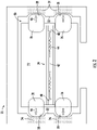
- Figure 2 schematically shows an example arrangement of a drive mechanism 24 and guiding surfaces 28 as seen from beneath the elevator car 22.
- the guiding surfaces 28 comprise recesses or grooves in oppositely facing walls 32 of the hoistway 30.
- the hoistway walls 32 include reinforced portions 34 near the guiding surfaces 28 to provide sufficient structural stability and strength to bear the loads associated with the drive members 26 engaging the guiding surfaces 28.
- the reinforced portions 34 include a material that is different than a remainder of the hoistway walls 32.
- the hoistway walls 32 primarily comprise a first material and the reinforced portions comprise a second, different material.
- the hoistway walls 32 comprise concrete and the reinforced portions 34 comprise a reinforced concrete having a different composition or density, for example.
- the reinforced portions 34 comprise metal, such as steel.
- the reinforced portions 34 may be formed as part of the hoistway walls 32 during construction of those walls or the reinforced portions 34 may be formed separately from the walls 32 and installed into the walls 32 during construction of the hoistway 30, for example.
- the drive mechanism 24 in this example includes motors 40 to cause rotation of the drive members 26.
- a controller 42 controls operation of the motors 40.
- a biasing mechanism 44 biases or urges the drive members 26 in an outward direction away from a center of the elevator car 22 as schematically represented by the arrows 46.
- the reinforced portions 34 of the walls 32 bear the loads associated with the force causing engagement between the drive members 26 and the guiding surfaces 28 and supporting the load of the elevator car 22.
- the drive members 26 have a contour that is complementary to a contour of the guiding surfaces 28.
- the guiding surfaces 28 in this example have a contour that is concave.
- the drive members 26 have a convex contour corresponding to the concave contour of the guiding surfaces 28.
- the complementary contours of the guiding surfaces 28 and the drive members 26 facilitate centering or tracking movement of the drive members 26 along the guide surfaces 28.
- the complementary contours facilitate moving the elevator car 22 along a desired path established by the guiding surfaces 28 within the hoistway 30.
- the position of the drive members 26 on the guiding surfaces 28 also serves to control proper positioning of the elevator car 22 relative to landings, for example, along the hoistway 30.
- the controller 42 monitors position and movement of the elevator car 22.
- the controller 42 obtains information from sensors associated with the elevator car 22 to determine a tilt or level condition of the elevator car 22. If the elevator car 22 were tilted toward the right or left according to the drawing, the controller 42 selectively adjusts movement of at least one of the drive members 26 to adjust the level of the elevator car 22. If such tilt occurs when the elevator car is stationary, the controller 42 may cause a selected number of the drive members 26 to rotate to achieve a desired car orientation. If tilt occurs during movement of the elevator car 22, the controller 42 may adjust the torque or speed of rotation of a selected number of the drive members 26 to achieve the desired car orientation.
- Figure 3 schematically illustrates another example embodiment.
- the guiding surfaces 28 comprise ribs or ridges along the hoistway walls 32 on opposite sides of the elevator car 22.
- the contour of the guiding surfaces 28 in this example is convex.
- the drive members 26 in this example embodiment include an at least partially concave contour that is complementary to the convex contour of the guiding surfaces 28. The complementary contours facilitate tracking or centering the drive members 26 along the guiding surfaces 28.
- Some example embodiments include a supplementary rail (not illustrated) within the hoistway 30.
- a supplementary rail may be used to facilitate guiding the vertical movement of the elevator car 22, provide a surface to be engaged by known types of elevator safety brakes, or both.
- guiding surfaces 28 and drive members 26 like those in the illustrated example embodiments, a separate guiderail may not be necessary.
- One of the features of the disclosed example embodiments is an efficient use of hoistway space. With guiding surfaces 28 on walls of the hoistway 30, separate guiderails or load bearing structures are not necessary within the hoistway 30. It is possible, therefore, to design a hoistway to be relatively smaller and closer in size to the outside envelope of the elevator car 22. This aspect of the disclosed example embodiments facilitates more efficient use of building space and can reduce the cost of an elevator system.
Landscapes
- Engineering & Computer Science (AREA)
- Mechanical Engineering (AREA)
- Structural Engineering (AREA)
- Civil Engineering (AREA)
- Automation & Control Theory (AREA)
- Lift-Guide Devices, And Elevator Ropes And Cables (AREA)
- Cage And Drive Apparatuses For Elevators (AREA)
Abstract
Description
- Elevator systems have proven useful for carrying passengers among various levels within a building. There are various types of elevator systems. For example, some elevator systems are considered hydraulic and include a piston or cylinder that expands or contracts to cause movement of the elevator car. Other elevator systems rely on suspending ropes or belts between the elevator car and a counterweight. A machine includes a traction sheave that causes movement of the ropes or belts to achieve the desired movement and positioning of the elevator car. Hydraulic systems are generally considered useful in buildings that have a few stories while roped systems are typically used in taller buildings.
- Each of the known types of elevator systems has features that present challenges for some implementations. For example, although roped elevator systems are useful in taller buildings, in ultra-high rise installations the ropes or belts are so long that they introduce appreciable mass and expense. The added mass of long ropes requires more power and that results in added power consumption cost. Sag due to stretch and bounce of the elevator car are other issues associated with longer ropes or belts. Additionally, longer ropes or belts and taller buildings are more susceptible to sway and drift, each of which requires additional equipment or modification to the elevator system. For such reasons, alternative elevator configurations could be useful.
- An illustrative example embodiment of an elevator includes an elevator car and a drive mechanism connected with the elevator car. The drive mechanism moves with the elevator car in a vertical direction. The drive mechanism includes drive members that are configured to engage surfaces on walls near opposite sides of the elevator car, climb along the surfaces to selectively cause movement of the elevator car, and selectively prevent movement of the elevator car when the drive members remain in a selected position relative to the wall.
- In addition to one or more of the features described above, or as an alternative, the drive members each comprise a wheel that is configured to selectively roll along one of the surfaces.
- In addition to one or more of the features described above, or as an alternative, each drive member is biased in a direction away from a center of the elevator car toward one of the surfaces.
- In addition to one or more of the features described above, or as an alternative, the drive members are biased in the direction with an aggregate force that is sufficient for engagement between the drive members and the surfaces to support a load of the elevator car.
- In addition to one or more of the features described above, or as an alternative, the elevator includes a controller that controls movement of the drive members, the controller being configured to adjust one of a torque or speed of rotation of at least one of the drive members to adjust a tilt of the elevator car.
- An illustrative example embodiment of an elevator system includes a hoistway including a plurality of walls. The guiding surfaces on at least two of the walls face in opposite directions. An elevator car is situated within the hoistway. A drive mechanism is connected with the elevator car. The drive mechanism moves with the elevator car along the hoistway. The drive mechanism includes drive members that engage the guiding surfaces, climb along the guiding surfaces to selectively cause movement of the elevator car, and selectively prevent movement of the elevator car when the drive members remain in a selected position relative to the walls.
- In addition to one or more of the features described above, or as an alternative, the elevator system includes load bearing structures within the walls in positions where the load bearing structures carry a load associated with engagement between the drive members and the guiding surfaces.
- In addition to one or more of the features described above, or as an alternative, the load bearing structures each comprise a column.
- In addition to one or more of the features described above, or as an alternative, the walls comprise a first material and each column comprises a second material that is different than the first material.
- In addition to one or more of the features described above, or as an alternative, each column comprises metal.
- In addition to one or more of the features described above, or as an alternative, each column comprises reinforced concrete.
- In addition to one or more of the features described above, or as an alternative, the guiding surfaces each have a contour, the drive members each have a complimentary contour, and the contours of the guiding surfaces and the drive members center the drive members on the guiding surfaces.
- In addition to one or more of the features described above, or as an alternative, the guiding surfaces each comprise a vertically oriented groove in a respective one of the walls, the contour of the guiding surfaces is concave, and the complimentary contour of the drive members is convex.
- In addition to one or more of the features described above, or as an alternative, the guiding surfaces each comprise a vertically oriented crowned surface on a respective one of the walls facing into the hoistway and, the contour of the guiding surfaces is convex, and the complimentary contour of the drive members is concave.
- In addition to one or more of the features described above, or as an alternative, the elevator system includes a controller that controls movement of the drive members, the controller being configured to selectively control movement of at least one of the drive members to adjust an angular orientation of the elevator car relative to at least one of the hoistway walls.
- In addition to one or more of the features described above, or as an alternative, the controller is configured to selectively control movement of the at least one of the drive members by adjusting one of a torque or speed of rotation of the at least one of the drive members.
- In addition to one or more of the features described above, or as an alternative, the drive members each comprise a wheel that is configured to selectively roll along one of the guiding surfaces.
- In addition to one or more of the features described above, or as an alternative, each drive member is biased in a direction away from a center of the hoistway toward one of the guiding surfaces.
- In addition to one or more of the features described above, or as an alternative, the drive members are biased in the direction with an aggregate force that is sufficient for engagement between the drive members and the guiding surfaces to support a load of the elevator car.
- The various features and advantages of at least one disclosed example embodiment will become apparent to those skilled in the art from the following detailed description. The drawings that accompany the detailed description can be briefly described as follows.
-
-
Figure 1 schematically illustrates selected portions of an example embodiment of an elevator system. -
Figure 2 schematically illustrates selected features of the embodiment ofFigure 1 viewed from underneath the elevator car. -
Figure 3 schematically illustrates selected features of another example embodiment viewed from underneath the elevator car. - Disclosed example embodiments include an elevator car drive mechanism that is supported for movement with the elevator car. The drive mechanism includes drive members that engage surfaces on hoistway walls that have sufficient structural strength to bear the load associated with engagement with the drive members and supporting the load of the elevator car. Disclosed example embodiments and others provide an efficient use of hoistway space.
-
Figure 1 schematically illustrates selected portions of an example embodiment of anelevator system 20. Anelevator car 22 has adrive mechanism 24 that is connected with theelevator car 22 and moves with theelevator car 22 in a vertical direction. Thedrive mechanism 24 includes drivemembers 26 that engage guidingsurfaces 28 on oppositely facing walls of ahoistway 30. - In this example, the
drive members 26 comprise wheels that are rotatable. Thedrive mechanism 24 causes thedrive members 26 to rotate while engaging the guidingsurfaces 28 to move theelevator car 22 in a vertical direction within thehoistway 30. Thedrive mechanism 24 causes thedrive members 26 to remain stationary relative to the guidingsurfaces 28 while engaging the guidingsurfaces 28 to maintain a stationary position of theelevator car 22 while supporting the load of theelevator car 22. -
Figure 2 schematically shows an example arrangement of adrive mechanism 24 and guidingsurfaces 28 as seen from beneath theelevator car 22. In this example, the guidingsurfaces 28 comprise recesses or grooves in oppositely facingwalls 32 of thehoistway 30. - The
hoistway walls 32 include reinforcedportions 34 near the guidingsurfaces 28 to provide sufficient structural stability and strength to bear the loads associated with thedrive members 26 engaging the guidingsurfaces 28. - The reinforced
portions 34 include a material that is different than a remainder of thehoistway walls 32. For example, thehoistway walls 32 primarily comprise a first material and the reinforced portions comprise a second, different material. In some embodiments, thehoistway walls 32 comprise concrete and the reinforcedportions 34 comprise a reinforced concrete having a different composition or density, for example. In some embodiments, the reinforcedportions 34 comprise metal, such as steel. The reinforcedportions 34 may be formed as part of thehoistway walls 32 during construction of those walls or the reinforcedportions 34 may be formed separately from thewalls 32 and installed into thewalls 32 during construction of thehoistway 30, for example. - The
drive mechanism 24 in this example includesmotors 40 to cause rotation of thedrive members 26. Acontroller 42 controls operation of themotors 40. Abiasing mechanism 44 biases or urges thedrive members 26 in an outward direction away from a center of theelevator car 22 as schematically represented by thearrows 46. The reinforcedportions 34 of thewalls 32 bear the loads associated with the force causing engagement between thedrive members 26 and the guiding surfaces 28 and supporting the load of theelevator car 22. - The
drive members 26 have a contour that is complementary to a contour of the guiding surfaces 28. The guiding surfaces 28 in this example have a contour that is concave. In this example, thedrive members 26 have a convex contour corresponding to the concave contour of the guiding surfaces 28. The complementary contours of the guiding surfaces 28 and thedrive members 26 facilitate centering or tracking movement of thedrive members 26 along the guide surfaces 28. The complementary contours facilitate moving theelevator car 22 along a desired path established by the guiding surfaces 28 within thehoistway 30. The position of thedrive members 26 on the guiding surfaces 28 also serves to control proper positioning of theelevator car 22 relative to landings, for example, along thehoistway 30. - The
controller 42 monitors position and movement of theelevator car 22. Thecontroller 42 obtains information from sensors associated with theelevator car 22 to determine a tilt or level condition of theelevator car 22. If theelevator car 22 were tilted toward the right or left according to the drawing, thecontroller 42 selectively adjusts movement of at least one of thedrive members 26 to adjust the level of theelevator car 22. If such tilt occurs when the elevator car is stationary, thecontroller 42 may cause a selected number of thedrive members 26 to rotate to achieve a desired car orientation. If tilt occurs during movement of theelevator car 22, thecontroller 42 may adjust the torque or speed of rotation of a selected number of thedrive members 26 to achieve the desired car orientation. -
Figure 3 schematically illustrates another example embodiment. In this example, the guiding surfaces 28 comprise ribs or ridges along thehoistway walls 32 on opposite sides of theelevator car 22. The contour of the guiding surfaces 28 in this example is convex. Thedrive members 26 in this example embodiment include an at least partially concave contour that is complementary to the convex contour of the guiding surfaces 28. The complementary contours facilitate tracking or centering thedrive members 26 along the guiding surfaces 28. - Some example embodiments include a supplementary rail (not illustrated) within the
hoistway 30. Such a rail may be used to facilitate guiding the vertical movement of theelevator car 22, provide a surface to be engaged by known types of elevator safety brakes, or both. With guidingsurfaces 28 and drivemembers 26 like those in the illustrated example embodiments, a separate guiderail may not be necessary. - One of the features of the disclosed example embodiments is an efficient use of hoistway space. With guiding
surfaces 28 on walls of thehoistway 30, separate guiderails or load bearing structures are not necessary within thehoistway 30. It is possible, therefore, to design a hoistway to be relatively smaller and closer in size to the outside envelope of theelevator car 22. This aspect of the disclosed example embodiments facilitates more efficient use of building space and can reduce the cost of an elevator system. - The preceding description is exemplary rather than limiting in nature. Variations and modifications to the disclosed examples may become apparent to those skilled in the art that do not necessarily depart from the essence of this invention. The scope of legal protection given to this invention can only be determined by studying the following claims.
Claims (15)
- An elevator, comprising:an elevator car; anda drive mechanism connected with the elevator car, the drive mechanism moving with the elevator car in a vertical direction, the drive mechanism including drive members that are configured to engage surfaces on walls near opposite sides of the elevator car, climb along the surfaces to selectively cause movement of the elevator car, and selectively prevent movement of the elevator car when the drive members remain in a selected position relative to the walls.
- The elevator of claim 1, wherein the drive members each comprise a wheel that is configured to selectively roll along one of the surfaces.
- The elevator of claim 1 or 2, wherein each drive member is biased in a direction away from a center of the elevator car toward one of the surfaces.
- The elevator of claim 3, wherein the drive members are biased in the direction with an aggregate force that is sufficient for engagement between the drive members and the surfaces to support a load of the elevator car.
- The elevator of any preceding claim, comprising a controller that controls movement of the drive members, the controller being configured to adjust one of a torque or speed of rotation of at least one of the drive members to adjust a tilt of the elevator car.
- An elevator system, comprising:a hoistway including a plurality of walls;guiding surfaces on at least two of the walls that face in opposite directions;an elevator car situated within the hoistway; anda drive mechanism connected with the elevator car, the drive mechanism moving with the elevator car along the hoistway, the drive mechanism including drive members that engage the guiding surfaces, climb along the guiding surfaces to selectively cause movement of the elevator car, and selectively prevent movement of the elevator car when the drive members remain in a selected position relative to the walls.
- The elevator system of claim 6, comprising load bearing structures within the walls in positions where the load bearing structures carry a load associated with engagement between the drive members and the guiding surfaces.
- The elevator system of claim 7, wherein the load bearing structures each comprise a column.
- The elevator system of claim 8, wherein each column comprises metal and/or reinforced concrete.
- The elevator system of claim 8 or 9, wherein the walls comprise a first material and each column comprises a second material that is different than the first material.
- The elevator system of any of claims 6 to 10, wherein the guiding surfaces each have a contour, the drive members each have a complimentary contour, and the contours of the guiding surfaces and the drive members center the drive members on the guiding surfaces.
- The elevator system of claim 11, wherein the guiding surfaces each comprise a vertically oriented groove in a respective one of the walls, the contour of the guiding surfaces is concave, and the complimentary contour of the drive members is convex.
- The elevator system of claim 11 or 12, wherein the guiding surfaces each comprise a vertically oriented crowned surface on a respective one of the walls facing into the hoistway and, the contour of the guiding surfaces is convex, and the complimentary contour of the drive members is concave.
- The elevator system of any of claims 6 to 13, comprising a controller that controls movement of the drive members, the controller being configured to selectively control movement of at least one of the drive members to adjust an angular orientation of the elevator car relative to at least one of the hoistway walls.
- The elevator system of claim 14, wherein the controller is configured to selectively control movement of the at least one of the drive members by adjusting one of a torque or speed of rotation of the at least one of the drive members.
Applications Claiming Priority (1)
| Application Number | Priority Date | Filing Date | Title |
|---|---|---|---|
| US17/088,758 US11667497B2 (en) | 2020-11-04 | 2020-11-04 | Wall climbing elevator |
Publications (2)
| Publication Number | Publication Date |
|---|---|
| EP4032845A1 true EP4032845A1 (en) | 2022-07-27 |
| EP4032845B1 EP4032845B1 (en) | 2025-02-26 |
Family
ID=78500469
Family Applications (1)
| Application Number | Title | Priority Date | Filing Date |
|---|---|---|---|
| EP21205915.8A Active EP4032845B1 (en) | 2020-11-04 | 2021-11-02 | Wall climbing elevator |
Country Status (4)
| Country | Link |
|---|---|
| US (1) | US11667497B2 (en) |
| EP (1) | EP4032845B1 (en) |
| KR (1) | KR20220060477A (en) |
| CN (1) | CN114436099B (en) |
Families Citing this family (2)
| Publication number | Priority date | Publication date | Assignee | Title |
|---|---|---|---|---|
| BR112022011691A2 (en) * | 2019-12-18 | 2022-09-06 | Inventio Ag | METHOD FOR RAISING AN ELEVATOR INSTALLATION |
| KR102859802B1 (en) | 2024-06-10 | 2025-09-12 | 김성헌 | Multifunctional moving wall exercise equipment |
Citations (2)
| Publication number | Priority date | Publication date | Assignee | Title |
|---|---|---|---|---|
| DE1251925B (en) * | 1964-01-13 | 1967-10-12 | Elevator | |
| US5464072A (en) * | 1992-10-27 | 1995-11-07 | Inventio Ag | Self-propelled elevator system |
Family Cites Families (16)
| Publication number | Priority date | Publication date | Assignee | Title |
|---|---|---|---|---|
| US2052690A (en) * | 1934-08-03 | 1936-09-01 | John T Austin | Elevator |
| EP0556595B1 (en) * | 1992-02-17 | 1996-03-27 | Inventio Ag | Passenger transport system |
| JPH06255948A (en) * | 1993-03-04 | 1994-09-13 | Toshiba Corp | Self-traveling elevator |
| US5566784A (en) * | 1994-07-08 | 1996-10-22 | Otis Elevator Company | Self-propelled elevator system |
| ZA964045B (en) * | 1995-06-02 | 1996-12-03 | Inventio Ag | Wheel frame for a lift |
| US6098758A (en) * | 1998-11-23 | 2000-08-08 | Lucent Technologies Inc. | Tower hoist mechanism confined within a tower interior |
| JP4161063B2 (en) * | 1999-10-22 | 2008-10-08 | 三菱電機株式会社 | Elevator device and guide device for elevator device |
| JP2004002020A (en) * | 2002-05-27 | 2004-01-08 | Inventio Ag | Elevator facility provided with several self-travelling cars and at least three adjacently arranged elevator hoistways |
| JP4456924B2 (en) * | 2004-05-06 | 2010-04-28 | 株式会社日立製作所 | Elevator equipment |
| AU2009328553B2 (en) * | 2008-12-18 | 2013-03-07 | Thoma Aufzuge Gmbh | Shaft frame for a lift system |
| WO2015189652A1 (en) * | 2014-06-11 | 2015-12-17 | Otis Elevator Company | Elevator system |
| CN109466995B (en) * | 2017-09-08 | 2020-11-27 | 奥的斯电梯公司 | Simple Supported Recirculating Elevator System |
| US11027944B2 (en) * | 2017-09-08 | 2021-06-08 | Otis Elevator Company | Climbing elevator transfer system and methods |
| US20220380179A1 (en) * | 2019-10-24 | 2022-12-01 | Hyprlift, Inc. | Elevator system with self-propelled autonomous cab |
| BR112022017766A2 (en) * | 2020-03-12 | 2022-10-18 | Inventio Ag | METHOD TO FORM GUIDE STRUCTURE TO GUIDE ELEVATOR CABIN IN ELEVATOR WELL |
| CN111439649A (en) * | 2020-03-16 | 2020-07-24 | 阿帕狮龙电梯科技(苏州)有限公司 | Anti-shaking device for elevator |
-
2020
- 2020-11-04 US US17/088,758 patent/US11667497B2/en active Active
-
2021
- 2021-07-21 CN CN202110823043.XA patent/CN114436099B/en active Active
- 2021-10-14 KR KR1020210136398A patent/KR20220060477A/en active Pending
- 2021-11-02 EP EP21205915.8A patent/EP4032845B1/en active Active
Patent Citations (2)
| Publication number | Priority date | Publication date | Assignee | Title |
|---|---|---|---|---|
| DE1251925B (en) * | 1964-01-13 | 1967-10-12 | Elevator | |
| US5464072A (en) * | 1992-10-27 | 1995-11-07 | Inventio Ag | Self-propelled elevator system |
Also Published As
| Publication number | Publication date |
|---|---|
| CN114436099A (en) | 2022-05-06 |
| US20220135375A1 (en) | 2022-05-05 |
| US11667497B2 (en) | 2023-06-06 |
| EP4032845B1 (en) | 2025-02-26 |
| CN114436099B (en) | 2024-11-01 |
| KR20220060477A (en) | 2022-05-11 |
Similar Documents
| Publication | Publication Date | Title |
|---|---|---|
| KR101208344B1 (en) | elevator | |
| KR100374659B1 (en) | Traction type elevator | |
| CN102239102B (en) | Use the elevator car location of vibration damper | |
| EP4032845B1 (en) | Wall climbing elevator | |
| US11286132B2 (en) | Enhancing the transport capacity of an elevator system | |
| EP3854742B1 (en) | Climbing elevator | |
| US20220185627A1 (en) | Running system for elevator, and multi-car elevator running system | |
| KR101245570B1 (en) | Method for installing an elevator, and elevator | |
| EP1591399A1 (en) | Elevator equipment | |
| US6619433B1 (en) | Elevator system using minimal building space | |
| WO2017144932A1 (en) | Variable cross-section elevator guide rail connector | |
| EP2900583A1 (en) | Elevator, and improvement for reducing elongation of the roping or belting of the elevator in a loading situation of the car of the elevator, and the use of pretensioning for bracing the roping or belting of the elevator | |
| CN113213311B (en) | Cantilever type climbing elevator | |
| US20220194742A1 (en) | Elevator system with a climbing counterweight | |
| CN113242837A (en) | Elevator installation with derailing protection | |
| WO2009110907A1 (en) | Secondary elevator car leveler | |
| US20070045053A1 (en) | Elevator apparatus | |
| EP3154893B1 (en) | Elevator system | |
| EP3730439A1 (en) | A solution for operating an elevator | |
| JP2024136715A (en) | Elevator guide rail device | |
| JP4936671B2 (en) | Elevator control device | |
| WO2022003979A1 (en) | Elevator ascending/descending body displacement suppression device | |
| CN114955759B (en) | Elevator system | |
| WO2019121219A1 (en) | Systems for coupling a suspension and/or traction medium to a load carrying structure, elevator installation and methods for moving a load | |
| KR102194964B1 (en) | Variable Speed Elevator System |
Legal Events
| Date | Code | Title | Description |
|---|---|---|---|
| PUAI | Public reference made under article 153(3) epc to a published international application that has entered the european phase |
Free format text: ORIGINAL CODE: 0009012 |
|
| STAA | Information on the status of an ep patent application or granted ep patent |
Free format text: STATUS: THE APPLICATION HAS BEEN PUBLISHED |
|
| AK | Designated contracting states |
Kind code of ref document: A1 Designated state(s): AL AT BE BG CH CY CZ DE DK EE ES FI FR GB GR HR HU IE IS IT LI LT LU LV MC MK MT NL NO PL PT RO RS SE SI SK SM TR |
|
| STAA | Information on the status of an ep patent application or granted ep patent |
Free format text: STATUS: REQUEST FOR EXAMINATION WAS MADE |
|
| 17P | Request for examination filed |
Effective date: 20230125 |
|
| RBV | Designated contracting states (corrected) |
Designated state(s): AL AT BE BG CH CY CZ DE DK EE ES FI FR GB GR HR HU IE IS IT LI LT LU LV MC MK MT NL NO PL PT RO RS SE SI SK SM TR |
|
| GRAP | Despatch of communication of intention to grant a patent |
Free format text: ORIGINAL CODE: EPIDOSNIGR1 |
|
| STAA | Information on the status of an ep patent application or granted ep patent |
Free format text: STATUS: GRANT OF PATENT IS INTENDED |
|
| INTG | Intention to grant announced |
Effective date: 20241111 |
|
| RAP3 | Party data changed (applicant data changed or rights of an application transferred) |
Owner name: OTIS ELEVATOR COMPANY |
|
| GRAS | Grant fee paid |
Free format text: ORIGINAL CODE: EPIDOSNIGR3 |
|
| GRAA | (expected) grant |
Free format text: ORIGINAL CODE: 0009210 |
|
| STAA | Information on the status of an ep patent application or granted ep patent |
Free format text: STATUS: THE PATENT HAS BEEN GRANTED |
|
| AK | Designated contracting states |
Kind code of ref document: B1 Designated state(s): AL AT BE BG CH CY CZ DE DK EE ES FI FR GB GR HR HU IE IS IT LI LT LU LV MC MK MT NL NO PL PT RO RS SE SI SK SM TR |
|
| REG | Reference to a national code |
Ref country code: GB Ref legal event code: FG4D |
|
| REG | Reference to a national code |
Ref country code: CH Ref legal event code: EP |
|
| REG | Reference to a national code |
Ref country code: DE Ref legal event code: R096 Ref document number: 602021026701 Country of ref document: DE |
|
| REG | Reference to a national code |
Ref country code: IE Ref legal event code: FG4D |
|
| REG | Reference to a national code |
Ref country code: NL Ref legal event code: MP Effective date: 20250226 |
|
| PG25 | Lapsed in a contracting state [announced via postgrant information from national office to epo] |
Ref country code: RS Free format text: LAPSE BECAUSE OF FAILURE TO SUBMIT A TRANSLATION OF THE DESCRIPTION OR TO PAY THE FEE WITHIN THE PRESCRIBED TIME-LIMIT Effective date: 20250526 |
|
| PG25 | Lapsed in a contracting state [announced via postgrant information from national office to epo] |
Ref country code: FI Free format text: LAPSE BECAUSE OF FAILURE TO SUBMIT A TRANSLATION OF THE DESCRIPTION OR TO PAY THE FEE WITHIN THE PRESCRIBED TIME-LIMIT Effective date: 20250226 |
|
| PG25 | Lapsed in a contracting state [announced via postgrant information from national office to epo] |
Ref country code: PL Free format text: LAPSE BECAUSE OF FAILURE TO SUBMIT A TRANSLATION OF THE DESCRIPTION OR TO PAY THE FEE WITHIN THE PRESCRIBED TIME-LIMIT Effective date: 20250226 |
|
| PG25 | Lapsed in a contracting state [announced via postgrant information from national office to epo] |
Ref country code: ES Free format text: LAPSE BECAUSE OF FAILURE TO SUBMIT A TRANSLATION OF THE DESCRIPTION OR TO PAY THE FEE WITHIN THE PRESCRIBED TIME-LIMIT Effective date: 20250226 |
|
| REG | Reference to a national code |
Ref country code: LT Ref legal event code: MG9D |
|
| PG25 | Lapsed in a contracting state [announced via postgrant information from national office to epo] |
Ref country code: NO Free format text: LAPSE BECAUSE OF FAILURE TO SUBMIT A TRANSLATION OF THE DESCRIPTION OR TO PAY THE FEE WITHIN THE PRESCRIBED TIME-LIMIT Effective date: 20250526 Ref country code: IS Free format text: LAPSE BECAUSE OF FAILURE TO SUBMIT A TRANSLATION OF THE DESCRIPTION OR TO PAY THE FEE WITHIN THE PRESCRIBED TIME-LIMIT Effective date: 20250626 |
|
| PG25 | Lapsed in a contracting state [announced via postgrant information from national office to epo] |
Ref country code: NL Free format text: LAPSE BECAUSE OF FAILURE TO SUBMIT A TRANSLATION OF THE DESCRIPTION OR TO PAY THE FEE WITHIN THE PRESCRIBED TIME-LIMIT Effective date: 20250226 |
|
| PG25 | Lapsed in a contracting state [announced via postgrant information from national office to epo] |
Ref country code: HR Free format text: LAPSE BECAUSE OF FAILURE TO SUBMIT A TRANSLATION OF THE DESCRIPTION OR TO PAY THE FEE WITHIN THE PRESCRIBED TIME-LIMIT Effective date: 20250226 |
|
| PG25 | Lapsed in a contracting state [announced via postgrant information from national office to epo] |
Ref country code: LV Free format text: LAPSE BECAUSE OF FAILURE TO SUBMIT A TRANSLATION OF THE DESCRIPTION OR TO PAY THE FEE WITHIN THE PRESCRIBED TIME-LIMIT Effective date: 20250226 Ref country code: PT Free format text: LAPSE BECAUSE OF FAILURE TO SUBMIT A TRANSLATION OF THE DESCRIPTION OR TO PAY THE FEE WITHIN THE PRESCRIBED TIME-LIMIT Effective date: 20250626 |
|
| PG25 | Lapsed in a contracting state [announced via postgrant information from national office to epo] |
Ref country code: GR Free format text: LAPSE BECAUSE OF FAILURE TO SUBMIT A TRANSLATION OF THE DESCRIPTION OR TO PAY THE FEE WITHIN THE PRESCRIBED TIME-LIMIT Effective date: 20250527 Ref country code: BG Free format text: LAPSE BECAUSE OF FAILURE TO SUBMIT A TRANSLATION OF THE DESCRIPTION OR TO PAY THE FEE WITHIN THE PRESCRIBED TIME-LIMIT Effective date: 20250226 |
|
| REG | Reference to a national code |
Ref country code: AT Ref legal event code: MK05 Ref document number: 1770487 Country of ref document: AT Kind code of ref document: T Effective date: 20250226 |
|
| PG25 | Lapsed in a contracting state [announced via postgrant information from national office to epo] |
Ref country code: SE Free format text: LAPSE BECAUSE OF FAILURE TO SUBMIT A TRANSLATION OF THE DESCRIPTION OR TO PAY THE FEE WITHIN THE PRESCRIBED TIME-LIMIT Effective date: 20250226 |
|
| PG25 | Lapsed in a contracting state [announced via postgrant information from national office to epo] |
Ref country code: SM Free format text: LAPSE BECAUSE OF FAILURE TO SUBMIT A TRANSLATION OF THE DESCRIPTION OR TO PAY THE FEE WITHIN THE PRESCRIBED TIME-LIMIT Effective date: 20250226 |
|
| PG25 | Lapsed in a contracting state [announced via postgrant information from national office to epo] |
Ref country code: DK Free format text: LAPSE BECAUSE OF FAILURE TO SUBMIT A TRANSLATION OF THE DESCRIPTION OR TO PAY THE FEE WITHIN THE PRESCRIBED TIME-LIMIT Effective date: 20250226 |
|
| PG25 | Lapsed in a contracting state [announced via postgrant information from national office to epo] |
Ref country code: IT Free format text: LAPSE BECAUSE OF FAILURE TO SUBMIT A TRANSLATION OF THE DESCRIPTION OR TO PAY THE FEE WITHIN THE PRESCRIBED TIME-LIMIT Effective date: 20250226 |
|
| PG25 | Lapsed in a contracting state [announced via postgrant information from national office to epo] |
Ref country code: AT Free format text: LAPSE BECAUSE OF FAILURE TO SUBMIT A TRANSLATION OF THE DESCRIPTION OR TO PAY THE FEE WITHIN THE PRESCRIBED TIME-LIMIT Effective date: 20250226 |
|
| PG25 | Lapsed in a contracting state [announced via postgrant information from national office to epo] |
Ref country code: CZ Free format text: LAPSE BECAUSE OF FAILURE TO SUBMIT A TRANSLATION OF THE DESCRIPTION OR TO PAY THE FEE WITHIN THE PRESCRIBED TIME-LIMIT Effective date: 20250226 Ref country code: EE Free format text: LAPSE BECAUSE OF FAILURE TO SUBMIT A TRANSLATION OF THE DESCRIPTION OR TO PAY THE FEE WITHIN THE PRESCRIBED TIME-LIMIT Effective date: 20250226 |
|
| PG25 | Lapsed in a contracting state [announced via postgrant information from national office to epo] |
Ref country code: RO Free format text: LAPSE BECAUSE OF FAILURE TO SUBMIT A TRANSLATION OF THE DESCRIPTION OR TO PAY THE FEE WITHIN THE PRESCRIBED TIME-LIMIT Effective date: 20250226 |
|
| PG25 | Lapsed in a contracting state [announced via postgrant information from national office to epo] |
Ref country code: SK Free format text: LAPSE BECAUSE OF FAILURE TO SUBMIT A TRANSLATION OF THE DESCRIPTION OR TO PAY THE FEE WITHIN THE PRESCRIBED TIME-LIMIT Effective date: 20250226 |
|
| REG | Reference to a national code |
Ref country code: DE Ref legal event code: R097 Ref document number: 602021026701 Country of ref document: DE |
|
| PLBE | No opposition filed within time limit |
Free format text: ORIGINAL CODE: 0009261 |
|
| STAA | Information on the status of an ep patent application or granted ep patent |
Free format text: STATUS: NO OPPOSITION FILED WITHIN TIME LIMIT |
|
| PGFP | Annual fee paid to national office [announced via postgrant information from national office to epo] |
Ref country code: DE Payment date: 20251022 Year of fee payment: 5 |
|
| PGFP | Annual fee paid to national office [announced via postgrant information from national office to epo] |
Ref country code: GB Payment date: 20251023 Year of fee payment: 5 |
|
| PGFP | Annual fee paid to national office [announced via postgrant information from national office to epo] |
Ref country code: FR Payment date: 20251022 Year of fee payment: 5 |
|
| 26N | No opposition filed |
Effective date: 20251127 |