EP4032763B1 - A brake system for braking a vehicle - Google Patents
A brake system for braking a vehicle Download PDFInfo
- Publication number
- EP4032763B1 EP4032763B1 EP21153227.0A EP21153227A EP4032763B1 EP 4032763 B1 EP4032763 B1 EP 4032763B1 EP 21153227 A EP21153227 A EP 21153227A EP 4032763 B1 EP4032763 B1 EP 4032763B1
- Authority
- EP
- European Patent Office
- Prior art keywords
- brake
- signal
- actuator
- circuit
- switching
- Prior art date
- Legal status (The legal status is an assumption and is not a legal conclusion. Google has not performed a legal analysis and makes no representation as to the accuracy of the status listed.)
- Active
Links
Images

Classifications
-
- B—PERFORMING OPERATIONS; TRANSPORTING
- B60—VEHICLES IN GENERAL
- B60T—VEHICLE BRAKE CONTROL SYSTEMS OR PARTS THEREOF; BRAKE CONTROL SYSTEMS OR PARTS THEREOF, IN GENERAL; ARRANGEMENT OF BRAKING ELEMENTS ON VEHICLES IN GENERAL; PORTABLE DEVICES FOR PREVENTING UNWANTED MOVEMENT OF VEHICLES; VEHICLE MODIFICATIONS TO FACILITATE COOLING OF BRAKES
- B60T17/00—Component parts, details, or accessories of power brake systems not covered by groups B60T8/00, B60T13/00 or B60T15/00, or presenting other characteristic features
- B60T17/18—Safety devices; Monitoring
- B60T17/22—Devices for monitoring or checking brake systems; Signal devices
- B60T17/221—Procedure or apparatus for checking or keeping in a correct functioning condition of brake systems
-
- B—PERFORMING OPERATIONS; TRANSPORTING
- B60—VEHICLES IN GENERAL
- B60T—VEHICLE BRAKE CONTROL SYSTEMS OR PARTS THEREOF; BRAKE CONTROL SYSTEMS OR PARTS THEREOF, IN GENERAL; ARRANGEMENT OF BRAKING ELEMENTS ON VEHICLES IN GENERAL; PORTABLE DEVICES FOR PREVENTING UNWANTED MOVEMENT OF VEHICLES; VEHICLE MODIFICATIONS TO FACILITATE COOLING OF BRAKES
- B60T13/00—Transmitting braking action from initiating means to ultimate brake actuator with power assistance or drive; Brake systems incorporating such transmitting means, e.g. air-pressure brake systems
- B60T13/74—Transmitting braking action from initiating means to ultimate brake actuator with power assistance or drive; Brake systems incorporating such transmitting means, e.g. air-pressure brake systems with electrical assistance or drive
- B60T13/741—Transmitting braking action from initiating means to ultimate brake actuator with power assistance or drive; Brake systems incorporating such transmitting means, e.g. air-pressure brake systems with electrical assistance or drive acting on an ultimate actuator
Definitions
- the present invention relates to a brake system for braking a vehicle, and an automotive actuator, e.g. for braking a wheel as part of the brake system.
- ASIL Automotive Safety Integrity Level
- ISO 26262 Functional Safety for Road Vehicles standard. This is an adaptation of the Safety Integrity Level (SIL) used in IEC 61508 for the automotive industry. This classification helps defining the safety requirements necessary to be in line with the ISO 26262 standard.
- the ASIL is established by performing a risk analysis of a potential hazard by looking at the Severity, Exposure and Controllability of the vehicle operating scenario. The safety goal for that hazard in turn carries the ASIL requirements.
- ASIL D dictates the highest integrity requirements on the product and ASIL A the lowest.
- Hazards that are identified as "Quality Management" (QM) do not dictate any safety requirements.
- QM Quality Management
- the required ASIL classification of components can be lowered through a technique referred to as ASIL Decomposition.
- a safety function implemented in an integrated device having high ASIL rating may be decomposed into independent sub-functions or components, with possibly lower ASIL. This can be advantageous, for example, with respect to improving system robustness and/or lowering production costs. However, it can be difficult to assure independent operation of the decomposed elements.
- the Smart Brake Fail Operational Decomposed Actuator safety concept can achieve ASIL D requirements on system level with the use of lower complexity (ASIL B) E/E hardware components.
- the Smart Brake Fail Operational Decomposed Actuator concept has two channels which both can be comprised of an ASIL B level control unit and inverter.
- each brake actuator controller comprises a main brake circuit configured to provide the power signal based on a first actuator control signal received from the central controller. Furthermore each brake actuator controller comprises a backup brake circuit configured to independently provide the power signal, in case the main brake circuit fails, based on a second actuator control signal received from the central controller.
- each brake actuator controller comprises a switching circuit. The switching circuit is configured to exclusively relay the power signal received from either the main brake circuit or the backup brake circuit to the brake actuation mechanism based on a switching signal received from the central controller independently of the actuator control signals.
- the central controller can be classified as ASIL-D to reliably decide whether to switch between the main and backup circuits in the respective brake actuator controller, so the required classification of these independent circuits can be lower, e.g. ASIL-B.
- the brake system preferably comprises an automotive actuator for applying a force or torque in an automotive component, in particular a brake actuator for braking a wheel.
- the actuator comprises an actuation mechanism.
- the actuation mechanism comprises a clamping device or other actuated device for applying an amount of braking to the wheel, e.g. by clamping a brake disc connected to the wheel.
- the actuation mechanism comprises or couples to an electric motor operably connected to the actuated device via a transmission.
- the automotive actuator further comprises an actuator controller, e.g. the brake actuator controller as described earlier.
- the actuator controller comprises a main circuit configured to provide a power signal to the electric motor based on a first actuator control signal received from a central controller via a main network port.
- the actuator controller comprises a backup circuit configured to independently provide the power signal, in case the main circuit fails, based on a second actuator control signal received from the central controller via a backup network port. Furthermore, the actuator controller comprises a switching circuit configured to exclusively relay the power signal received from either the main circuit or the backup circuit to the actuation mechanism based on a switching signal received independently of the actuator control signals via a signal port separate from the main and backup network ports.
- FIG 1 illustrates a vehicle 1000 with a brake system 100 for braking a vehicle 1000.
- the brake system comprises a respective brake actuator controller 10 for one or more wheels 30 of the vehicle 1000, preferably each wheel 30.
- the brake actuator controller 10 is configured to apply a respective power signal "Sp" to power a respective brake actuation mechanism 20 for applying an amount of braking BR to the wheel 30. For example, this can be based at least on a respective actuator control signal "Sa" received by the brake actuator controller 10.
- the brake system comprises a central controller 50.
- the central controller 50 is configured to control the braking of the vehicle by sending the respective actuator control signal "Sa" to the respective brake actuator controller 10 of each wheel 30. For example, this can be based on a brake intent signal "Si" received by the central controller 50.
- each brake actuator controller 10 comprises at least a main brake circuit 11 and a backup brake circuit 12.
- the main brake circuit 11 is configured to provide the power signal "Sp" based on a first actuator control signal "Sa", e.g. received from the central controller 50.
- the backup brake circuit 12 is configured to (independently) provide the power signal "Sp", e.g. in case the main brake circuit 11 fails, based on a second actuator control signal "Sa” which can also be received from the central controller 50.
- the brake actuator controller 10 comprises a switching circuit 13 configured to exclusively relay the power signal "Sp" received from either the main brake circuit 11 or the backup brake circuit 12 to the brake actuation mechanism 20. Most preferably, this based on a switching signal "Sw” received independently of the actuator control signals Sa. For example, the switching signal "Sw" is also received from the central controller 50.
- the main brake circuit 11 is configured to provide a power signal "Sp" to the brake motor 10m based on a first actuator control signal "Sa” received from a central controller 50 via a main network port 51p.
- the backup brake circuit 12 is configured to independently provide the power signal "Sp", in case the main brake circuit 11 fails, based on a second actuator control signal "Sa" received from the central controller 50 via a backup network port 52p.
- the switching circuit 13 is configured to exclusively relay the power signal "Sp" received from either the main brake circuit 11 or the backup brake circuit 12 to the brake actuation mechanism 20 based on a switching signal "Sw” received independently of the actuator control signals Sa via a signal port 13p separate from the main and backup network ports 51p,52p.
- An electric brake for a vehicle typically has an electromechanical actuation mechanism, configured to press a friction brake lining for braking against a brake body that is mounted to a vehicle wheel.
- the brake body, or rotor is typically a brake disc or a brake drum.
- the actuation device typically has an electric motor and a rotation-to-translation conversion gear that converts a rotary driving motion of the electric motor into a translational motion for pressing the friction brake lining against the brake body.
- Worm gears such as spindle gears or roller worm drives, are often used as rotation-to-translation conversion gears. It is also possible to convert the rotary motion into a translational motion by means of a pivotable cam, for instance.
- a step-down gear for instance in the form of a planetary gear, is often placed between the electric motor and the rotation-to-translation conversion gear.
- Self-boosting electromechanical vehicle brakes have a self-booster that converts a frictional force, exerted by the rotating brake body against the friction brake lining that is pressed for braking against the brake body, into a contact pressure, which presses the friction brake lining against the brake body in addition to a contact pressure that is exerted by the actuation device.
- Wedge, ramp, and lever mechanisms are suitable for the self-boosting.
- the brake intent signal "Si" is generated based on user interaction with a service and/or parking brake 60, and/or generated autonomously by a vehicle motion control system (not shown).
- the brake intent signal "Si” is received directly or indirectly from the service and/or parking brake 60.
- the brake intent signal "Si” is generated when a brake pedal is operated.
- the brake intent signal "Si” is generated autonomously by a motion controller of the vehicle.
- the vehicle comprises a sensor system configured to detect impending danger and activate the brake system accordingly. So it will be understood that the brake system can also be operated as part of a partially or fully self-driving vehicle.
- the central controller 50 is configured to receive a sensor signal "Ss" from a motion sensor 40 measuring a motion of the vehicle and/or wheel 30. In one embodiment, the central controller 50 is configured to send the switching signal "Sw" to the switching circuit 13 for relaying the power signal "Sp" of the backup brake circuit 12 instead of the main brake circuit 11, or vice versa, based on the sensor signal "Ss".
- the central controller 50 is configured to send the switching signal "Sw" to one or more brake actuator controllers 10 for switching the switching circuit 13, if the central controller 50 determines, based on the sensor signal "Ss", that the measured motion of the vehicle and/or wheel 30 deviates from an expected motion corresponding to the actuator control signal "Sa” and/or brake intent signal "Si".
- the motion sensor 40 comprises a wheel speed sensor configured to individually measure the wheel speed of each wheel of the vehicle.
- the central controller 50 is configured to receive a respective wheel speed signal from each wheel 30.
- the central controller 50 is configured to send the switching signal "Sw" for switching to the backup brake circuit 12 exclusively to the respective brake actuator controller 10 of the specific wheel.
- the switching signal "Sw” is sent if it is determined that a measured wheel speed of a specific wheel deviates from an expected wheel speed corresponding to the actuator control signal "Sa" (that was sent to the respective brake actuator controller 10 of the specific wheel 30). In this way, only the faulty brake actuator controllers 10 of a specific wheel may need to be switched to its backup circuit, while the controllers of the other wheels can remain to use their main circuit.
- the motion sensor 40 comprises an inertial sensor configured to measure acceleration and/or deceleration of the vehicle.
- the central controller 50 is configured to receive an acceleration and/or deceleration signal from the inertial sensor and send the switching signal "Sw" for switching each of the brake actuator controller 10 from the main brake circuit 11 to the backup brake circuit 12, or vice versa.
- the problem may be immediately remedied by switching each of the brake actuator controller 10 to an alternate brake circuit 11. For example, this can alleviate braking problems even if it cannot be directly determined which specific controller has failed.
- the central controller 50 is configured to periodically test the backup brake circuit 12 by switching the brake actuator controller 10 to use the backup brake circuit 12 instead of main brake circuit 11 absent any detected failure in the brake system 100.
- the central controller 50 is configured to periodically test the backup brake circuit 12 when the vehicle is parked by applying a parking brake using the backup brake circuit 12 and monitor subsequent motion of the vehicle and/or wheels. For example, when the vehicle or wheel starts moving after the brake is actuated using the backup brake circuit 12, this is an indication there is a fault in the backup brake circuit 12. By testing this during parking there is relatively low risk associated with the test.
- FIG 2 illustrates further details of a preferred components in a brake system 100.
- the central controller 50 is configured to communicate with each brake actuator controller 10 using a set of at least two separate parallel cables between the central controller 50 and respective brake actuator controller 10. For example, a first cable is configured to send the actuator control signal "Sa" to the main brake circuit 11 and a second cable is configured to send the actuator control signal "Sa" to the backup brake circuit 12.
- the central controller 50 is configured to send the actuator control signal "Sa” using two or more network cables arranged in parallel between the central controller 50 and brake actuator controller 10.
- the actuator control signal "Sa” is communicated using a message based protocol such as CAN or Ethernet. Such protocol can provide flexibility in communicating various types of information.
- the central controller 50 is configured to communicate the switching signal "Sw" to each brake actuator controller 10 using at least one additional cable, e.g. separate from the set of at cables used for communicating the actuator control signal "Sa".
- the actuator control signal "Sw” is communicated by applying a fixed voltage on a respective signal line.
- the switching signal "Sw” can be simply communicated by switching between a high and low voltage, e.g. 5v and 0V, or any other voltage. Such way of communication can be relatively simple and robust so the chance of failure can be minimized.
- the central controller 50 is configured to communicate the switching signal "Sw" to each brake actuator controller 10 using two signal lines.
- the brake actuator controller 10 is configured to determine the switching signal "Sw" based on a combination of voltages received from the two signal lines. For example, in normal operation, an "on" or “high” voltage signal (1) is continuously provided on each of the signal lines. When both of the signals is switched to an "off' or “low” voltage (0) this can be used as an indication to operate the switching circuit 13. This redundancy may prevent inadvertent switching when one of the signal lines is broken. Of course also other combinations of signals can be used. By switching the switching circuit 13 using a limited number of signals, e.g. one or two bits, the chance of failure for such switching can be lowered. In principle also more than two, e.g. three, signal lines can be used for further redundancy.
- each brake circuit 11,12 comprises a separate set of components.
- the set of components includes a network port 11p, 12p configured to receive a respective actuator control signal "Sa".
- the set of components includes an inverter 11i, 12i configured to generate a respective power signal "Sp”.
- the set of components includes a brake actuator processor 11c, 12c configured to control the main brake circuit 11 to generate the power signal "Sp" based on the actuator control signal "Sa”.
- (the components of) the respective brake circuits 11,12 are classified as ASIL-B or ASIL-C.
- the brake actuator processor 11c, 12c can be a relatively simple processor, e.g. single core as opposed to a dual-core lockstep processor which is typically needed for being rated as ASIL-D.
- the switching circuit 13 comprises a signal port 13p configured to receive the switching signal "Sw", e.g. one or more voltages.
- the switching circuit 13 comprises a switching relay 13r controlled by the switching signal "Sw" to form an electrical connection between an output of a respective inverter 11i, 12i of either the main brake circuit 11 or the backup brake circuit 12.
- at least the components of the switching circuit 13 are classified as ASIL-D.
- the ASIL-D classification of the switching circuit 13 can be used to apply reliable ASIL decomposition of components in the brake actuator controller 10 by improved separation between the operation of the main and backup brake circuits, which can thus be of lower classification ASIL-B without compromising safety.
- the central controller 50 comprises at least one signal port 54s for receiving a sensor signal "Ss" from a motion sensor 40 measuring a motion of the vehicle and/or wheel 30.
- the central controller 50 comprises a sensor signal acquisition unit 54a configured to generate a conditioned sensor signal "Sc" based on the sensor signal "Ss" received from the signal port 54s.
- the central controller 50 comprises a black-box actuator safety unit 54b configured to generate a safety mechanism result Sf based on the conditioned sensor signal "Sc".
- the safety mechanism result Sf can also be based on an indication Sa' of the actuator control signal "Sa", e.g.
- the central controller 50 comprises an actuator control safety unit 50f.
- the actuator control safety unit 50f is configured to generate the switching signal "Sw” based on the safety mechanism result Sf, and/or to selectively output the actuator control signal "Sa" to one of a main network port 51p and a backup network port 52p based on the safety mechanism result Sf.
- these ports 51p,52p are connected to the respective network ports 11p,12p of the main and backup brake circuits 11,12.
- the central controller 50 comprises a brake system control module 50m configured to determine an individual brake intent for each wheel 30 based on the received brake intent signal "Si".
- the brake system control module 50m may also include other considerations, e.g. other sensor inputs.
- the brake system control module 50m may implement an anti-lock braking system (ABS), electronic stability control (ESC), or other traction control.
- the central controller 50 comprises an actuator control module 50a configured to individually generate a respective actuator control signal "Sa" for each wheel based on the individual brake intent signal.
- the actuator control module 50a is configured to generate the generate a respective actuator control signal "Sa" for each wheel further based on a (conditioned) sensor signal "Sc" indicating a motion of the wheel.
- the central controller 50 is classified as ASIL-D.
- the central controller 50 comprises a dual core lockstep processor.
- the units and modules as described herein with reference to the central controller 50 can be implemented in hardware and/or software components. While the functions are depicted as separate blocks, these blocks or functions can also be integrated, further subdivided, or omitted (e.g. because their respective function is not strictly necessary).
- the functions of the brake system control module 50m and the actuator control module 50a can be combined.
- the functions of the black-box actuator safety unit 54b can be integrated in the actuator control safety unit 50f and can also be made part of the brake system control module 50a.
- the sensor signal acquisition unit 54a may be omitted and the sensor signal "Ss" directly input into the black-box actuator safety unit 54b and/or actuator control safety unit 50f.
- the present teachings are especially beneficial in the control of a brake system, in principle the present teachings can also be applied to other automotive components that benefit from reliable control, in particular allowing the use of cost-effective redundant circuits while maintaining the highest vehicle safety requirements.
Landscapes
- Engineering & Computer Science (AREA)
- Transportation (AREA)
- Mechanical Engineering (AREA)
- Valves And Accessory Devices For Braking Systems (AREA)
- Regulating Braking Force (AREA)
Description
- The present invention relates to a brake system for braking a vehicle, and an automotive actuator, e.g. for braking a wheel as part of the brake system.
- As background,
DE 10 2018 222794 A1DE 10 2011 084534 A1WO 2020/204509 A1 describe (parking) brake systems which can switch to a type of backup brake in case the main brake fails. Automotive Safety Integrity Level (ASIL) is a risk classification scheme defined by the ISO 26262 - Functional Safety for Road Vehicles standard. This is an adaptation of the Safety Integrity Level (SIL) used in IEC 61508 for the automotive industry. This classification helps defining the safety requirements necessary to be in line with the ISO 26262 standard. The ASIL is established by performing a risk analysis of a potential hazard by looking at the Severity, Exposure and Controllability of the vehicle operating scenario. The safety goal for that hazard in turn carries the ASIL requirements. There are four ASILs identified by the standard: ASIL A, ASIL B, ASIL C, ASIL D. ASIL D dictates the highest integrity requirements on the product and ASIL A the lowest. Hazards that are identified as "Quality Management" (QM) do not dictate any safety requirements. Under certain circumstances, the required ASIL classification of components can be lowered through a technique referred to as ASIL Decomposition. For example, a safety function implemented in an integrated device having high ASIL rating may be decomposed into independent sub-functions or components, with possibly lower ASIL. This can be advantageous, for example, with respect to improving system robustness and/or lowering production costs. However, it can be difficult to assure independent operation of the decomposed elements. - There is yet a need for an improved brake system and automotive actuator control which allows the use of cost-effective redundant circuits while maintaining the highest vehicle safety requirements.
- The inventors find that, from the results of vehicle simulation analyses, the safety and stability of a vehicle can typically be ensured only with a fail operational concept and the use of expensive ASIL D compliant E/E Hardware components. So the use of redundant ASIL B components is typically not feasible without a special concept as this is not compliant to the ASIL D level diagnostic coverage and failure rate (especially to mitigate the random E/E Hw failures). As described herein, the Smart Brake Fail Operational Decomposed Actuator safety concept can achieve ASIL D requirements on system level with the use of lower complexity (ASIL B) E/E hardware components. According to a preferred embodiment, the Smart Brake Fail Operational Decomposed Actuator concept has two channels which both can be comprised of an ASIL B level control unit and inverter. According to the decomposition rules of the ISO 26262 standard this by itself may not fulfill the integrity of the transition to degraded mode (safe state) and the ASIL D diagnostic coverage and failure rate of the system. To compensate for this the present teachings provide an additional mechanism which can independently select a respective channel.
- The invention provides a brake system for braking a vehicle. The brake system comprises a respective brake actuator controller, preferably at least one for each wheel. The respective brake actuator controller is configured to apply a respective power signal to power a respective brake actuation mechanism. The respective brake actuation mechanism can then apply an amount of braking to the wheel. In particular, this can be based at least on a respective actuator control signal received by the brake actuator controller. The brake system further comprises a central controller configured to control the braking of the vehicle. This can be done by sending the respective actuator control signal to the respective brake actuator controller of each wheel, e.g. based on a brake intent signal received by the central controller. As described herein each brake actuator controller comprises a main brake circuit configured to provide the power signal based on a first actuator control signal received from the central controller. Furthermore each brake actuator controller comprises a backup brake circuit configured to independently provide the power signal, in case the main brake circuit fails, based on a second actuator control signal received from the central controller. Advantageously, each brake actuator controller comprises a switching circuit. The switching circuit is configured to exclusively relay the power signal received from either the main brake circuit or the backup brake circuit to the brake actuation mechanism based on a switching signal received from the central controller independently of the actuator control signals. For example, the central controller can be classified as ASIL-D to reliably decide whether to switch between the main and backup circuits in the respective brake actuator controller, so the required classification of these independent circuits can be lower, e.g. ASIL-B.
- The brake system according to the invention preferably comprises an automotive actuator for applying a force or torque in an automotive component, in particular a brake actuator for braking a wheel. The actuator comprises an actuation mechanism. For example, the actuation mechanism comprises a clamping device or other actuated device for applying an amount of braking to the wheel, e.g. by clamping a brake disc connected to the wheel. Furthermore, the actuation mechanism comprises or couples to an electric motor operably connected to the actuated device via a transmission. The automotive actuator further comprises an actuator controller, e.g. the brake actuator controller as described earlier. In particular, the actuator controller comprises a main circuit configured to provide a power signal to the electric motor based on a first actuator control signal received from a central controller via a main network port. Furthermore, the actuator controller comprises a backup circuit configured to independently provide the power signal, in case the main circuit fails, based on a second actuator control signal received from the central controller via a backup network port. Furthermore, the actuator controller comprises a switching circuit configured to exclusively relay the power signal received from either the main circuit or the backup circuit to the actuation mechanism based on a switching signal received independently of the actuator control signals via a signal port separate from the main and backup network ports.
- These and other features, aspects, and advantages of the brake system of the present invention will become better understood from the following description, appended claims, and accompanying drawing wherein:
-
FIG 1 illustrates a vehicle with a brake system; -
FIG 2 illustrates further details of a preferred brake system. - Terminology used for describing particular embodiments is not intended to be limiting of the invention. As used herein, the singular forms "a", "an" and "the" are intended to include the plural forms as well, unless the context clearly indicates otherwise. The term "and/or" includes any and all combinations of one or more of the associated listed items. It will be understood that the terms "comprises" and/or "comprising" specify the presence of stated features but do not preclude the presence or addition of one or more other features. It will be further understood that when a particular step of a method is referred to as subsequent to another step, it can directly follow said other step or one or more intermediate steps may be carried out before carrying out the particular step, unless specified otherwise. Likewise it will be understood that when a connection between structures or components is described, this connection may be established directly or through intermediate structures or components unless specified otherwise.
- The invention is described more fully hereinafter with reference to the accompanying drawings, in which embodiments of the invention are shown. In the drawings, the absolute and relative sizes of systems, components, layers, and regions may be exaggerated for clarity. Embodiments may be described with reference to schematic and/or cross-section illustrations of possibly idealized embodiments and intermediate structures of the invention. In the description and drawings, like numbers refer to like elements throughout. Relative terms as well as derivatives thereof should be construed to refer to the orientation as then described or as shown in the drawing under discussion. These relative terms are for convenience of description and do not require that the system be constructed or operated in a particular orientation unless stated otherwise.
-
FIG 1 illustrates avehicle 1000 with abrake system 100 for braking avehicle 1000. - In some embodiments, e.g. as shown, the brake system comprises a respective
brake actuator controller 10 for one ormore wheels 30 of thevehicle 1000, preferably eachwheel 30. In one embodiment, thebrake actuator controller 10 is configured to apply a respective power signal "Sp" to power a respectivebrake actuation mechanism 20 for applying an amount of braking BR to thewheel 30. For example, this can be based at least on a respective actuator control signal "Sa" received by thebrake actuator controller 10. In other or further embodiments, e.g. as shown, the brake system comprises acentral controller 50. In one embodiment, thecentral controller 50 is configured to control the braking of the vehicle by sending the respective actuator control signal "Sa" to the respectivebrake actuator controller 10 of eachwheel 30. For example, this can be based on a brake intent signal "Si" received by thecentral controller 50. - In some embodiments, each
brake actuator controller 10 comprises at least amain brake circuit 11 and abackup brake circuit 12. In one embodiment, themain brake circuit 11 is configured to provide the power signal "Sp" based on a first actuator control signal "Sa", e.g. received from thecentral controller 50. In another or further embodiment, thebackup brake circuit 12 is configured to (independently) provide the power signal "Sp", e.g. in case themain brake circuit 11 fails, based on a second actuator control signal "Sa" which can also be received from thecentral controller 50. In a preferred embodiment, thebrake actuator controller 10 comprises a switchingcircuit 13 configured to exclusively relay the power signal "Sp" received from either themain brake circuit 11 or thebackup brake circuit 12 to thebrake actuation mechanism 20. Most preferably, this based on a switching signal "Sw" received independently of the actuator control signals Sa. For example, the switching signal "Sw" is also received from thecentral controller 50. - Aspects of the present invention can also be embodied as an integrated brake actuator for braking a
wheel 30. For example, the brake actuator comprises the integrated components of thebrake actuator controller 10 andbrake actuation mechanism 20. In one embodiment, thebrake actuation mechanism 20 comprises aclamping device 20c for applying an amount of braking BR to thewheel 30, e.g. by clamping a brake disc connected to thewheel 30, and an (electric)brake motor 20m operably connected to theclamping device 20c via abrake transmission 20t. In another or further embodiment, thebrake actuator controller 10 comprises amain brake circuit 11, abackup brake circuit 12, and aswitching circuit 13, as described herein. For example, themain brake circuit 11 is configured to provide a power signal "Sp" to the brake motor 10m based on a first actuator control signal "Sa" received from acentral controller 50 via amain network port 51p. For example, thebackup brake circuit 12 is configured to independently provide the power signal "Sp", in case themain brake circuit 11 fails, based on a second actuator control signal "Sa" received from thecentral controller 50 via abackup network port 52p. For example, the switchingcircuit 13 is configured to exclusively relay the power signal "Sp" received from either themain brake circuit 11 or thebackup brake circuit 12 to thebrake actuation mechanism 20 based on a switching signal "Sw" received independently of the actuator control signals Sa via asignal port 13p separate from the main andbackup network ports - An electric brake for a vehicle typically has an electromechanical actuation mechanism, configured to press a friction brake lining for braking against a brake body that is mounted to a vehicle wheel. The brake body, or rotor, is typically a brake disc or a brake drum. The actuation device typically has an electric motor and a rotation-to-translation conversion gear that converts a rotary driving motion of the electric motor into a translational motion for pressing the friction brake lining against the brake body. Worm gears, such as spindle gears or roller worm drives, are often used as rotation-to-translation conversion gears. It is also possible to convert the rotary motion into a translational motion by means of a pivotable cam, for instance. A step-down gear, for instance in the form of a planetary gear, is often placed between the electric motor and the rotation-to-translation conversion gear. Self-boosting electromechanical vehicle brakes have a self-booster that converts a frictional force, exerted by the rotating brake body against the friction brake lining that is pressed for braking against the brake body, into a contact pressure, which presses the friction brake lining against the brake body in addition to a contact pressure that is exerted by the actuation device. Wedge, ramp, and lever mechanisms are suitable for the self-boosting.
- In some embodiments, the brake intent signal "Si" is generated based on user interaction with a service and/or
parking brake 60, and/or generated autonomously by a vehicle motion control system (not shown). In one embodiment, the brake intent signal "Si" is received directly or indirectly from the service and/orparking brake 60. For example, the brake intent signal "Si" is generated when a brake pedal is operated. In another or further embodiment (not shown), the brake intent signal "Si" is generated autonomously by a motion controller of the vehicle. For example, the vehicle comprises a sensor system configured to detect impending danger and activate the brake system accordingly. So it will be understood that the brake system can also be operated as part of a partially or fully self-driving vehicle. - In some embodiments, the
central controller 50 is configured to receive a sensor signal "Ss" from amotion sensor 40 measuring a motion of the vehicle and/orwheel 30. In one embodiment, thecentral controller 50 is configured to send the switching signal "Sw" to the switchingcircuit 13 for relaying the power signal "Sp" of thebackup brake circuit 12 instead of themain brake circuit 11, or vice versa, based on the sensor signal "Ss". In another or further embodiment, thecentral controller 50 is configured to send the switching signal "Sw" to one or morebrake actuator controllers 10 for switching the switchingcircuit 13, if thecentral controller 50 determines, based on the sensor signal "Ss", that the measured motion of the vehicle and/orwheel 30 deviates from an expected motion corresponding to the actuator control signal "Sa" and/or brake intent signal "Si". - In some embodiments, the
motion sensor 40 comprises a wheel speed sensor configured to individually measure the wheel speed of each wheel of the vehicle. In one embodiment, thecentral controller 50 is configured to receive a respective wheel speed signal from eachwheel 30. In another or further embodiment, thecentral controller 50 is configured to send the switching signal "Sw" for switching to thebackup brake circuit 12 exclusively to the respectivebrake actuator controller 10 of the specific wheel. For example, the switching signal "Sw" is sent if it is determined that a measured wheel speed of a specific wheel deviates from an expected wheel speed corresponding to the actuator control signal "Sa" (that was sent to the respectivebrake actuator controller 10 of the specific wheel 30). In this way, only the faultybrake actuator controllers 10 of a specific wheel may need to be switched to its backup circuit, while the controllers of the other wheels can remain to use their main circuit. - In other or further embodiments, the
motion sensor 40 comprises an inertial sensor configured to measure acceleration and/or deceleration of the vehicle. In one embodiment, thecentral controller 50 is configured to receive an acceleration and/or deceleration signal from the inertial sensor and send the switching signal "Sw" for switching each of thebrake actuator controller 10 from themain brake circuit 11 to thebackup brake circuit 12, or vice versa. For example, in case an overall braking behavior of the vehicle deviates from expected behavior, the problem may be immediately remedied by switching each of thebrake actuator controller 10 to analternate brake circuit 11. For example, this can alleviate braking problems even if it cannot be directly determined which specific controller has failed. - In some embodiments, the
central controller 50 is configured to periodically test thebackup brake circuit 12 by switching thebrake actuator controller 10 to use thebackup brake circuit 12 instead ofmain brake circuit 11 absent any detected failure in thebrake system 100. In one embodiment, thecentral controller 50 is configured to periodically test thebackup brake circuit 12 when the vehicle is parked by applying a parking brake using thebackup brake circuit 12 and monitor subsequent motion of the vehicle and/or wheels. For example, when the vehicle or wheel starts moving after the brake is actuated using thebackup brake circuit 12, this is an indication there is a fault in thebackup brake circuit 12. By testing this during parking there is relatively low risk associated with the test. - In some embodiments, the
central controller 50 is configured to output a warning signal if it is determined that either themain brake circuit 11 orbackup brake circuit 12 fails expected operation. For example, the warning signal can be used to trigger a visual and/or auditory warning signal on a dashboard of the vehicle. In one embodiment, thecentral controller 50 is configured to switch operation of the vehicle to a degraded mode based on the warning signal. In another or further embodiment, operation of the vehicle is limited in the degraded mode compared to normal mode (when thebrake system 100 is fully functional). For example, the maximum speed of the vehicle may be limited in the degraded mode. -
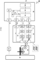
FIG 2 illustrates further details of a preferred components in abrake system 100. - In some embodiments, the
central controller 50 is configured to communicate with eachbrake actuator controller 10 using a set of at least two separate parallel cables between thecentral controller 50 and respectivebrake actuator controller 10. For example, a first cable is configured to send the actuator control signal "Sa" to themain brake circuit 11 and a second cable is configured to send the actuator control signal "Sa" to thebackup brake circuit 12. In one embodiment, thecentral controller 50 is configured to send the actuator control signal "Sa" using two or more network cables arranged in parallel between thecentral controller 50 andbrake actuator controller 10. In another or further embodiment, the actuator control signal "Sa" is communicated using a message based protocol such as CAN or Ethernet. Such protocol can provide flexibility in communicating various types of information. - In a preferred embodiment, e.g. as shown, the
central controller 50 is configured to communicate the switching signal "Sw" to eachbrake actuator controller 10 using at least one additional cable, e.g. separate from the set of at cables used for communicating the actuator control signal "Sa". In one embodiment, the actuator control signal "Sw" is communicated by applying a fixed voltage on a respective signal line. For example, the switching signal "Sw" can be simply communicated by switching between a high and low voltage, e.g. 5v and 0V, or any other voltage. Such way of communication can be relatively simple and robust so the chance of failure can be minimized. In one embodiment, thecentral controller 50 is configured to communicate the switching signal "Sw" to eachbrake actuator controller 10 using two signal lines. In another or further embodiment, thebrake actuator controller 10 is configured to determine the switching signal "Sw" based on a combination of voltages received from the two signal lines. For example, in normal operation, an "on" or "high" voltage signal (1) is continuously provided on each of the signal lines. When both of the signals is switched to an "off' or "low" voltage (0) this can be used as an indication to operate the switchingcircuit 13. This redundancy may prevent inadvertent switching when one of the signal lines is broken. Of course also other combinations of signals can be used. By switching the switchingcircuit 13 using a limited number of signals, e.g. one or two bits, the chance of failure for such switching can be lowered. In principle also more than two, e.g. three, signal lines can be used for further redundancy. - In some embodiments, e.g. as shown, each
brake circuit network port inverter brake actuator processor main brake circuit 11 to generate the power signal "Sp" based on the actuator control signal "Sa". In one embodiment, (the components of) therespective brake circuits brake actuator processor - In some embodiments, the switching
circuit 13 comprises asignal port 13p configured to receive the switching signal "Sw", e.g. one or more voltages. In other or further embodiments, the switchingcircuit 13 comprises aswitching relay 13r controlled by the switching signal "Sw" to form an electrical connection between an output of arespective inverter main brake circuit 11 or thebackup brake circuit 12. In a preferred embodiment, at least the components of the switchingcircuit 13 are classified as ASIL-D. As will be appreciated, the ASIL-D classification of the switchingcircuit 13 can be used to apply reliable ASIL decomposition of components in thebrake actuator controller 10 by improved separation between the operation of the main and backup brake circuits, which can thus be of lower classification ASIL-B without compromising safety. - In some embodiments, e.g. as shown, the
central controller 50 comprises at least onesignal port 54s for receiving a sensor signal "Ss" from amotion sensor 40 measuring a motion of the vehicle and/orwheel 30. In one embodiment, thecentral controller 50 comprises a sensorsignal acquisition unit 54a configured to generate a conditioned sensor signal "Sc" based on the sensor signal "Ss" received from thesignal port 54s. In another or further embodiment, thecentral controller 50 comprises a black-boxactuator safety unit 54b configured to generate a safety mechanism result Sf based on the conditioned sensor signal "Sc". The safety mechanism result Sf can also be based on an indication Sa' of the actuator control signal "Sa", e.g. to compare the measured brake behavior (based on the sensor signal "Ss") with the expected brake behavior (based on the indication Sa'). In another or further embodiment, thecentral controller 50 comprises an actuatorcontrol safety unit 50f. For example, the actuatorcontrol safety unit 50f is configured to generate the switching signal "Sw" based on the safety mechanism result Sf, and/or to selectively output the actuator control signal "Sa" to one of amain network port 51p and abackup network port 52p based on the safety mechanism result Sf. For example, theseports respective network ports backup brake circuits - In some embodiments, e.g. as shown, the
central controller 50 comprises a brakesystem control module 50m configured to determine an individual brake intent for eachwheel 30 based on the received brake intent signal "Si". The brakesystem control module 50m may also include other considerations, e.g. other sensor inputs. For example, the brakesystem control module 50m may implement an anti-lock braking system (ABS), electronic stability control (ESC), or other traction control. In one embodiment, thecentral controller 50 comprises anactuator control module 50a configured to individually generate a respective actuator control signal "Sa" for each wheel based on the individual brake intent signal. In another or further embodiment, theactuator control module 50a is configured to generate the generate a respective actuator control signal "Sa" for each wheel further based on a (conditioned) sensor signal "Sc" indicating a motion of the wheel. - Preferably, the
central controller 50 is classified as ASIL-D. For example, thecentral controller 50 comprises a dual core lockstep processor. By providing the highly reliablecentral controller 50 with the decision function whether to use themain brake circuit 11 or thebackup brake circuit 12 in each of thebrake actuator controllers 10, the overall chance of failure is further lowered. Typically, the units and modules as described herein with reference to thecentral controller 50 can be implemented in hardware and/or software components. While the functions are depicted as separate blocks, these blocks or functions can also be integrated, further subdivided, or omitted (e.g. because their respective function is not strictly necessary). For example, the functions of the brakesystem control module 50m and theactuator control module 50a can be combined. For example, the functions of the black-boxactuator safety unit 54b can be integrated in the actuatorcontrol safety unit 50f and can also be made part of the brakesystem control module 50a. For example, the sensorsignal acquisition unit 54a may be omitted and the sensor signal "Ss" directly input into the black-boxactuator safety unit 54b and/or actuatorcontrol safety unit 50f. Also other variation will be apparent to the skilled person having the benefit of the present teachings. While it is recognized that the present teachings are especially beneficial in the control of a brake system, in principle the present teachings can also be applied to other automotive components that benefit from reliable control, in particular allowing the use of cost-effective redundant circuits while maintaining the highest vehicle safety requirements. - In interpreting the appended claims, it should be understood that the word "comprising" does not exclude the presence of other elements or acts than those listed in a given claim; the word "a" or "an" preceding an element does not exclude the presence of a plurality of such elements; any reference signs in the claims do not limit their scope; several "means" may be represented by the same or different item(s) or implemented structure or function; any of the disclosed devices or portions thereof may be combined together or separated into further portions unless specifically stated otherwise. Where one claim refers to another claim, this may indicate synergetic advantage achieved by the combination of their respective features. But the mere fact that certain measures are recited in mutually different claims does not indicate that a combination of these measures cannot also be used to advantage. The present embodiments may thus include all working combinations of the claims wherein each claim can in principle refer to any preceding claim unless clearly excluded by context.
- brake actuator controller (10), main brake circuit (11), backup brake circuit (12), network ports (11p, 12p), brake actuator processors (11c, 12c), inverters (11i, 12i), switching circuit (13), signal port (13p), switching relay (13r); brake actuation mechanism (20), brake motor (20m), clamping device (20c); wheel (30); sensor (40); central controller (50), brake system control module (50m), actuator control module (50a), actuator control safety unit (50f), network ports (51p,52p), switching signal port (53p), sensor signal port (54s), sensor signal acquisition unit (54a), black-box actuator safety unit (54b); brake action (BR), actuator control signal (Sa), brake intent signal (Si), switching signal (Sw), sensor signal (Ss).
Claims (15)
- A brake system (100) for braking a vehicle (1000), the brake system comprisingfor at least one, preferably each, wheel (30) of the vehicle, a respective brake actuator controller (10) configured to apply a respective power signal (Sp) to power a respective brake actuation mechanism (20) for applying an amount of braking (BR) to the wheel (30) based at least on a respective actuator control signal (Sa) received by the brake actuator controller (10);a central controller (50) configured to control the braking of the vehicle by sending the respective actuator control signal (Sa) to each respective brake actuator controller (10) based on a brake intent signal (Si) received by the central controller (50);wherein each brake actuator controller (10) comprisescharacterised in thata main brake circuit (11) configured to provide the power signal (Sp) based on a first actuator control signal (Sa) received from the central controller (50),a backup brake circuit (12) configured to provide the power signal (Sp), in case the main brake circuit (11) fails, anda switching circuit (13) configured to exclusively relay the power signal (Sp) received from either the main brake circuit (11) or the backup brake circuit (12) to the brake actuation mechanism (20)the backup brake circuit (12) is configured to independently provide the power signal (Sp) based on a second actuator control signal (Sa) received from the central controller (50), andthe switching circuit (13) is configured to relay the power signal (Sp) based on a switching signal (Sw) received from the central controller (50) independently of the actuator control signals (Sa).
- The brake system according to the preceding claim, wherein the central controller (50) is configured to receive a sensor signal (Ss) from a motion sensor (40) measuring a motion of the vehicle and/or wheel (30), wherein the central controller (50) is configured to send the switching signal (Sw) to the switching circuit (13) for relaying the power signal (Sp) of the backup brake circuit (12) instead of the main brake circuit (11), or vice versa, based on the sensor signal (Ss).
- The brake system according to the preceding claim, wherein the central controller (50) is configured to send the switching signal (Sw) to one or more brake actuator controllers (10) for switching the switching circuit (13), if the central controller (50) determines, based on the sensor signal (Ss), that the measured motion of the vehicle and/or wheel (30) deviates from an expected motion corresponding to the actuator control signal (Sa) and/or brake intent signal (Si).
- The brake system according to the preceding claim, wherein the motion sensor (40) comprises a wheel speed sensor configured to individually measure the wheel speed of each wheel of the vehicle, wherein the central controller (50) is configured to receive a respective wheel speed signal from each wheel (30) and, if it is determined that a measured wheel speed of a specific wheel deviates from an expected wheel speed corresponding to the actuator control signal (Sa), that was sent to the respective brake actuator controller (10) of the specific wheel (30), send the switching signal (Sw) for switching to the backup brake circuit (12) exclusively to the respective brake actuator controller (10) of the specific wheel.
- The brake system according to any of claims 2 - 4, wherein the motion sensor (40) comprises an inertial sensor configured to measure acceleration and/or deceleration of the vehicle, wherein the central controller (50) is configured to receive an acceleration and/or deceleration signal from the inertial sensor and send the switching signal (Sw) for switching each of the brake actuator controller (10) from the main brake circuit (11) to the backup brake circuit (12), or vice versa.
- The brake system according to any of the preceding claims, wherein each brake circuit (11,12) comprises a separate set of components includinga network port (11p, 12p) configured to receive a respective actuator control signal (Sa),an inverter (11i, 12i) configured to generate a respective power signal (Sp), anda brake actuator processor (11c, 12c) configured to control the main brake circuit (11) to generate the power signal (Sp) based on the actuator control signal (Sa).wherein the components of the respective brake circuits (11,12) are classified as ASIL-B or ASIL-C.
- The brake system according to any of the preceding claims, wherein the switching circuit (13) comprises components includinga signal port (13p) configured to receive the switching signal (Sw), e.g. one or more voltages, anda switching relay (13r) controlled by the switching signal (Sw) to form an electrical connection between an output of a respective inverter (11i, 12i) of either the main brake circuit (11) or the backup brake circuit (12).wherein the components of the switching circuit (13) and the central controller (50) are classified as ASIL-D.
- The brake system according to any of the preceding claims, wherein the brake intent signal (Si) is generated based on user interaction with a service and/or parking brake (60), and/or generated autonomously by a vehicle motion control system.
- The brake system according to any of the preceding claims, wherein the central controller (50) is configured to communicate with each brake actuator controller (10) using a set of at least two separate network cables arranged in parallel between the central controller (50) and respective brake actuator controller (10), wherein a first network cable is configured to send the actuator control signal (Sa) to the main brake circuit (11) and a second network cable is configured to send the actuator control signal (Sa) to the backup brake circuit (12), wherein the actuator control signal (Sa) is communicated using a message based protocol such as CAN or Ethernet, wherein the central controller (50) is configured to communicate the switching signal (Sw) to each brake actuator controller (10) using at least one additional cable, separate from the set of network cables used for communicating the actuator control signal (Sa), wherein the switching signal (Sw) is communicated by applying a fixed voltage on a respective signal line.
- The brake system according to any of the preceding claims, wherein the central controller (50) is configured to communicate the switching signal (Sw) to each brake actuator controller (10) using two signal lines, wherein the brake actuator controller (10) is configured to determine the switching signal (Sw) based on a combination of voltages received from the two signal lines.
- The brake system according to any of the preceding claims, wherein the central controller (50) is configured to periodically test the backup brake circuit (12) by switching the brake actuator controller (10) to use the backup brake circuit (12) instead of main brake circuit (11) absent any detected failure in the brake system (100).
- The brake system according to any of the preceding claims, wherein the central controller (50) is configured to output a warning signal if it is determined that either the main brake circuit (11) or backup brake circuit (12) fails expected operation, wherein the central controller (50) is configured to switch operation of the vehicle to a degraded mode based on the warning signal.
- The brake system according to any of the preceding claims, wherein the central controller (50) comprisesat least one signal port (54s) for receiving a sensor signal (Ss) from a motion sensor (40) measuring a motion of the vehicle and/or wheel (30);a sensor signal acquisition unit (54a) configured to generate a conditioned sensor signal (Sc) based on the sensor signal (Ss) received from the signal port (54s);a black-box actuator safety unit (54b) configured to generate a safety mechanism result (Sf) based on the conditioned sensor signal (Sc), and an indication (Sa') of actuator control signal (Sa);an actuator control safety unit (50f) configured togenerate the switching signal (Sw) based on the safety mechanism result (Sf), andto selectively output the actuator control signal (Sa) to one of a main network port (51p) and a backup network port (52p), connected to the respective network ports (11p, 12p) of the main and backup brake circuits (11,12), based on the safety mechanism result (Sf);a brake system control module (50m) configured to determine an individual brake intent for each wheel (30) based on the received brake intent signal (Si); andan actuator control module (50a) configured to individually generate a respective actuator control signal (Sa) for each wheel based on the individual brake intent signal.
- The brake system according to any of the preceding claims, comprising an automotive actuator for applying a force or torque in an automotive component, in particular a brake actuator for braking a wheel, the automotive actuator comprisingan actuation mechanism (20) comprisingan actuated device (20c) for applying an amount of force or torque, andan electric motor (20m) operably connected to the actuated device (20c) via a transmission (20t); andan actuator controller (10) comprisinga main circuit (11) configured to provide a power signal (Sp) to the electric motor (20m) based on a first actuator control signal (Sa) received from a central controller (50) via a main network port (51p),a backup circuit (12) configured to independently provide the power signal (Sp), in case the main circuit (11) fails, based on a second actuator control signal (Sa) received from the central controller (50) via a backup network port (52p), anda switching circuit (13) configured to exclusively relay the power signal (Sp) received from either the main circuit (11) or the backup circuit (12) to the actuation mechanism (20) based on a switching signal (Sw) received independently of the actuator control signals (Sa) via a signal port (13p) separate from the main and backup network ports (51p,52p).
- The brake system according to the preceding claim wherein the automotive actuator is configured as a brake actuator for braking a wheel (30), wherein the actuator controller (10) is configured to apply a respective power signal (Sp) to power the actuation mechanism (20), e.g. including a clamping device configured to clamp a brake disc connected to the wheel (30), for applying an amount of braking (BR) to the wheel (30) based at least on the respective actuator control signal (Sa) and the switching signal (Sw) received by the actuator controller (10).
Priority Applications (1)
| Application Number | Priority Date | Filing Date | Title |
|---|---|---|---|
| EP21153227.0A EP4032763B1 (en) | 2021-01-25 | 2021-01-25 | A brake system for braking a vehicle |
Applications Claiming Priority (1)
| Application Number | Priority Date | Filing Date | Title |
|---|---|---|---|
| EP21153227.0A EP4032763B1 (en) | 2021-01-25 | 2021-01-25 | A brake system for braking a vehicle |
Publications (2)
| Publication Number | Publication Date |
|---|---|
| EP4032763A1 EP4032763A1 (en) | 2022-07-27 |
| EP4032763B1 true EP4032763B1 (en) | 2024-12-04 |
Family
ID=74236048
Family Applications (1)
| Application Number | Title | Priority Date | Filing Date |
|---|---|---|---|
| EP21153227.0A Active EP4032763B1 (en) | 2021-01-25 | 2021-01-25 | A brake system for braking a vehicle |
Country Status (1)
| Country | Link |
|---|---|
| EP (1) | EP4032763B1 (en) |
Families Citing this family (2)
| Publication number | Priority date | Publication date | Assignee | Title |
|---|---|---|---|---|
| EP4043304B1 (en) * | 2021-02-15 | 2024-03-27 | Hitachi Astemo Netherlands B.V. | Automotive motion control system and automotive actuator |
| CN117818563B (en) * | 2023-12-27 | 2025-04-15 | 上海同驭汽车科技有限公司 | Wheel side controller taking over method and vehicle |
Family Cites Families (3)
| Publication number | Priority date | Publication date | Assignee | Title |
|---|---|---|---|---|
| DE102011084534A1 (en) * | 2010-10-18 | 2012-04-19 | Continental Teves Ag & Co. Ohg | Fail-safe parking brake for motor vehicles |
| DE102018222794A1 (en) * | 2018-12-21 | 2020-06-25 | Audi Ag | Parking brake system |
| WO2020204509A1 (en) * | 2019-03-29 | 2020-10-08 | Mando Corporation | Brake system |
-
2021
- 2021-01-25 EP EP21153227.0A patent/EP4032763B1/en active Active
Also Published As
| Publication number | Publication date |
|---|---|
| EP4032763A1 (en) | 2022-07-27 |
Similar Documents
| Publication | Publication Date | Title |
|---|---|---|
| EP2284054B1 (en) | Decentralized electric brake system | |
| US10081345B2 (en) | Electric brake system | |
| JP5443354B2 (en) | Brake device for vehicle and method for operating vehicle brake device | |
| US8185288B2 (en) | Brake system for a vehicle and a method for operating a brake system for a vehicle | |
| US6157887A (en) | Brake system for a motor vehicle | |
| EP2094549B1 (en) | Reduced power mode for an aircraft electric brake system | |
| JP2009541133A (en) | Parking brake mechanism for automobiles | |
| CN115210119B (en) | Braking system with redundant parking brake actuation | |
| JP2001523619A (en) | Electromechanical brake device | |
| GB2483744A (en) | Braking system where a brake actuator is controlled based on information relating to another brake actuator | |
| EP4032763B1 (en) | A brake system for braking a vehicle | |
| KR20220163638A (en) | Brake Apparatus for Vehicle and Control Method Therefor | |
| US20200198611A1 (en) | Brake system for a transportation vehicle and transportation vehicle with a brake system | |
| JPWO2018181807A1 (en) | Vehicle brake system | |
| CN105452049A (en) | Brake system for rail cars, brake control device for rail car, and brake control method for rail cars | |
| CN116691620A (en) | Braking System | |
| CN117500705A (en) | Electromechanical braking system and method for motor vehicle | |
| WO2024227346A1 (en) | Dual-backup vehicle braking system and vehicle | |
| CN120530038A (en) | Method for operating a braking system with increased safety in a backup level, and braking system with increased safety in a backup level | |
| US20240039451A1 (en) | Motor control apparatus and motor control system | |
| EP4043304B1 (en) | Automotive motion control system and automotive actuator | |
| KR102953500B1 (en) | Brake system and controlling method thereof | |
| EP4610118A1 (en) | Brake system with control redundancy | |
| CN112622848B (en) | Brake-by-wire system and car | |
| KR20230006666A (en) | Brake system and controlling method thereof |
Legal Events
| Date | Code | Title | Description |
|---|---|---|---|
| PUAI | Public reference made under article 153(3) epc to a published international application that has entered the european phase |
Free format text: ORIGINAL CODE: 0009012 |
|
| STAA | Information on the status of an ep patent application or granted ep patent |
Free format text: STATUS: THE APPLICATION HAS BEEN PUBLISHED |
|
| AK | Designated contracting states |
Kind code of ref document: A1 Designated state(s): AL AT BE BG CH CY CZ DE DK EE ES FI FR GB GR HR HU IE IS IT LI LT LU LV MC MK MT NL NO PL PT RO RS SE SI SK SM TR |
|
| STAA | Information on the status of an ep patent application or granted ep patent |
Free format text: STATUS: REQUEST FOR EXAMINATION WAS MADE |
|
| 17P | Request for examination filed |
Effective date: 20230123 |
|
| RBV | Designated contracting states (corrected) |
Designated state(s): AL AT BE BG CH CY CZ DE DK EE ES FI FR GB GR HR HU IE IS IT LI LT LU LV MC MK MT NL NO PL PT RO RS SE SI SK SM TR |
|
| GRAP | Despatch of communication of intention to grant a patent |
Free format text: ORIGINAL CODE: EPIDOSNIGR1 |
|
| STAA | Information on the status of an ep patent application or granted ep patent |
Free format text: STATUS: GRANT OF PATENT IS INTENDED |
|
| INTG | Intention to grant announced |
Effective date: 20240620 |
|
| GRAS | Grant fee paid |
Free format text: ORIGINAL CODE: EPIDOSNIGR3 |
|
| GRAA | (expected) grant |
Free format text: ORIGINAL CODE: 0009210 |
|
| STAA | Information on the status of an ep patent application or granted ep patent |
Free format text: STATUS: THE PATENT HAS BEEN GRANTED |
|
| RAP3 | Party data changed (applicant data changed or rights of an application transferred) |
Owner name: HITACHI ASTEMO NETHERLANDS B.V. |
|
| AK | Designated contracting states |
Kind code of ref document: B1 Designated state(s): AL AT BE BG CH CY CZ DE DK EE ES FI FR GB GR HR HU IE IS IT LI LT LU LV MC MK MT NL NO PL PT RO RS SE SI SK SM TR |
|
| REG | Reference to a national code |
Ref country code: CH Ref legal event code: EP |
|
| REG | Reference to a national code |
Ref country code: DE Ref legal event code: R096 Ref document number: 602021022674 Country of ref document: DE |
|
| REG | Reference to a national code |
Ref country code: IE Ref legal event code: FG4D |
|
| REG | Reference to a national code |
Ref country code: LT Ref legal event code: MG9D |
|
| REG | Reference to a national code |
Ref country code: NL Ref legal event code: MP Effective date: 20241204 |
|
| PG25 | Lapsed in a contracting state [announced via postgrant information from national office to epo] |
Ref country code: HR Free format text: LAPSE BECAUSE OF FAILURE TO SUBMIT A TRANSLATION OF THE DESCRIPTION OR TO PAY THE FEE WITHIN THE PRESCRIBED TIME-LIMIT Effective date: 20241204 |
|
| PG25 | Lapsed in a contracting state [announced via postgrant information from national office to epo] |
Ref country code: FI Free format text: LAPSE BECAUSE OF FAILURE TO SUBMIT A TRANSLATION OF THE DESCRIPTION OR TO PAY THE FEE WITHIN THE PRESCRIBED TIME-LIMIT Effective date: 20241204 |
|
| PG25 | Lapsed in a contracting state [announced via postgrant information from national office to epo] |
Ref country code: BG Free format text: LAPSE BECAUSE OF FAILURE TO SUBMIT A TRANSLATION OF THE DESCRIPTION OR TO PAY THE FEE WITHIN THE PRESCRIBED TIME-LIMIT Effective date: 20241204 |
|
| PG25 | Lapsed in a contracting state [announced via postgrant information from national office to epo] |
Ref country code: ES Free format text: LAPSE BECAUSE OF FAILURE TO SUBMIT A TRANSLATION OF THE DESCRIPTION OR TO PAY THE FEE WITHIN THE PRESCRIBED TIME-LIMIT Effective date: 20241204 |
|
| PG25 | Lapsed in a contracting state [announced via postgrant information from national office to epo] |
Ref country code: NO Free format text: LAPSE BECAUSE OF FAILURE TO SUBMIT A TRANSLATION OF THE DESCRIPTION OR TO PAY THE FEE WITHIN THE PRESCRIBED TIME-LIMIT Effective date: 20250304 |
|
| PG25 | Lapsed in a contracting state [announced via postgrant information from national office to epo] |
Ref country code: LV Free format text: LAPSE BECAUSE OF FAILURE TO SUBMIT A TRANSLATION OF THE DESCRIPTION OR TO PAY THE FEE WITHIN THE PRESCRIBED TIME-LIMIT Effective date: 20241204 Ref country code: GR Free format text: LAPSE BECAUSE OF FAILURE TO SUBMIT A TRANSLATION OF THE DESCRIPTION OR TO PAY THE FEE WITHIN THE PRESCRIBED TIME-LIMIT Effective date: 20250305 |
|
| PG25 | Lapsed in a contracting state [announced via postgrant information from national office to epo] |
Ref country code: RS Free format text: LAPSE BECAUSE OF FAILURE TO SUBMIT A TRANSLATION OF THE DESCRIPTION OR TO PAY THE FEE WITHIN THE PRESCRIBED TIME-LIMIT Effective date: 20250304 |
|
| PG25 | Lapsed in a contracting state [announced via postgrant information from national office to epo] |
Ref country code: NL Free format text: LAPSE BECAUSE OF FAILURE TO SUBMIT A TRANSLATION OF THE DESCRIPTION OR TO PAY THE FEE WITHIN THE PRESCRIBED TIME-LIMIT Effective date: 20241204 |
|
| REG | Reference to a national code |
Ref country code: AT Ref legal event code: MK05 Ref document number: 1747873 Country of ref document: AT Kind code of ref document: T Effective date: 20241204 |
|
| PG25 | Lapsed in a contracting state [announced via postgrant information from national office to epo] |
Ref country code: SM Free format text: LAPSE BECAUSE OF FAILURE TO SUBMIT A TRANSLATION OF THE DESCRIPTION OR TO PAY THE FEE WITHIN THE PRESCRIBED TIME-LIMIT Effective date: 20241204 |
|
| PG25 | Lapsed in a contracting state [announced via postgrant information from national office to epo] |
Ref country code: PL Free format text: LAPSE BECAUSE OF FAILURE TO SUBMIT A TRANSLATION OF THE DESCRIPTION OR TO PAY THE FEE WITHIN THE PRESCRIBED TIME-LIMIT Effective date: 20241204 |
|
| PG25 | Lapsed in a contracting state [announced via postgrant information from national office to epo] |
Ref country code: IS Free format text: LAPSE BECAUSE OF FAILURE TO SUBMIT A TRANSLATION OF THE DESCRIPTION OR TO PAY THE FEE WITHIN THE PRESCRIBED TIME-LIMIT Effective date: 20250404 |
|
| PG25 | Lapsed in a contracting state [announced via postgrant information from national office to epo] |
Ref country code: PT Free format text: LAPSE BECAUSE OF FAILURE TO SUBMIT A TRANSLATION OF THE DESCRIPTION OR TO PAY THE FEE WITHIN THE PRESCRIBED TIME-LIMIT Effective date: 20250404 |
|
| PG25 | Lapsed in a contracting state [announced via postgrant information from national office to epo] |
Ref country code: EE Free format text: LAPSE BECAUSE OF FAILURE TO SUBMIT A TRANSLATION OF THE DESCRIPTION OR TO PAY THE FEE WITHIN THE PRESCRIBED TIME-LIMIT Effective date: 20241204 |
|
| PG25 | Lapsed in a contracting state [announced via postgrant information from national office to epo] |
Ref country code: AT Free format text: LAPSE BECAUSE OF FAILURE TO SUBMIT A TRANSLATION OF THE DESCRIPTION OR TO PAY THE FEE WITHIN THE PRESCRIBED TIME-LIMIT Effective date: 20241204 Ref country code: RO Free format text: LAPSE BECAUSE OF FAILURE TO SUBMIT A TRANSLATION OF THE DESCRIPTION OR TO PAY THE FEE WITHIN THE PRESCRIBED TIME-LIMIT Effective date: 20241204 |
|
| PG25 | Lapsed in a contracting state [announced via postgrant information from national office to epo] |
Ref country code: SK Free format text: LAPSE BECAUSE OF FAILURE TO SUBMIT A TRANSLATION OF THE DESCRIPTION OR TO PAY THE FEE WITHIN THE PRESCRIBED TIME-LIMIT Effective date: 20241204 |
|
| PG25 | Lapsed in a contracting state [announced via postgrant information from national office to epo] |
Ref country code: CZ Free format text: LAPSE BECAUSE OF FAILURE TO SUBMIT A TRANSLATION OF THE DESCRIPTION OR TO PAY THE FEE WITHIN THE PRESCRIBED TIME-LIMIT Effective date: 20241204 |
|
| PG25 | Lapsed in a contracting state [announced via postgrant information from national office to epo] |
Ref country code: IT Free format text: LAPSE BECAUSE OF FAILURE TO SUBMIT A TRANSLATION OF THE DESCRIPTION OR TO PAY THE FEE WITHIN THE PRESCRIBED TIME-LIMIT Effective date: 20241204 |
|
| REG | Reference to a national code |
Ref country code: CH Ref legal event code: PL |
|
| REG | Reference to a national code |
Ref country code: DE Ref legal event code: R097 Ref document number: 602021022674 Country of ref document: DE |
|
| PG25 | Lapsed in a contracting state [announced via postgrant information from national office to epo] |
Ref country code: SE Free format text: LAPSE BECAUSE OF FAILURE TO SUBMIT A TRANSLATION OF THE DESCRIPTION OR TO PAY THE FEE WITHIN THE PRESCRIBED TIME-LIMIT Effective date: 20241204 |
|
| PG25 | Lapsed in a contracting state [announced via postgrant information from national office to epo] |
Ref country code: MC Free format text: LAPSE BECAUSE OF FAILURE TO SUBMIT A TRANSLATION OF THE DESCRIPTION OR TO PAY THE FEE WITHIN THE PRESCRIBED TIME-LIMIT Effective date: 20241204 Ref country code: LU Free format text: LAPSE BECAUSE OF NON-PAYMENT OF DUE FEES Effective date: 20250125 |
|
| PG25 | Lapsed in a contracting state [announced via postgrant information from national office to epo] |
Ref country code: DK Free format text: LAPSE BECAUSE OF FAILURE TO SUBMIT A TRANSLATION OF THE DESCRIPTION OR TO PAY THE FEE WITHIN THE PRESCRIBED TIME-LIMIT Effective date: 20241204 |
|
| PLBE | No opposition filed within time limit |
Free format text: ORIGINAL CODE: 0009261 |
|
| STAA | Information on the status of an ep patent application or granted ep patent |
Free format text: STATUS: NO OPPOSITION FILED WITHIN TIME LIMIT |
|
| PG25 | Lapsed in a contracting state [announced via postgrant information from national office to epo] |
Ref country code: BE Free format text: LAPSE BECAUSE OF NON-PAYMENT OF DUE FEES Effective date: 20250131 |
|
| PG25 | Lapsed in a contracting state [announced via postgrant information from national office to epo] |
Ref country code: CH Free format text: LAPSE BECAUSE OF NON-PAYMENT OF DUE FEES Effective date: 20250131 |
|
| REG | Reference to a national code |
Ref country code: BE Ref legal event code: MM Effective date: 20250131 |
|
| 26N | No opposition filed |
Effective date: 20250905 |
|
| GBPC | Gb: european patent ceased through non-payment of renewal fee |
Effective date: 20250304 |
|
| PG25 | Lapsed in a contracting state [announced via postgrant information from national office to epo] |
Ref country code: GB Free format text: LAPSE BECAUSE OF NON-PAYMENT OF DUE FEES Effective date: 20250304 |
|
| PGFP | Annual fee paid to national office [announced via postgrant information from national office to epo] |
Ref country code: FR Payment date: 20251217 Year of fee payment: 6 |
|
| PG25 | Lapsed in a contracting state [announced via postgrant information from national office to epo] |
Ref country code: IE Free format text: LAPSE BECAUSE OF NON-PAYMENT OF DUE FEES Effective date: 20250125 |
|
| PGFP | Annual fee paid to national office [announced via postgrant information from national office to epo] |
Ref country code: DE Payment date: 20251217 Year of fee payment: 6 |