EP4032755A1 - Support structure for a vehicle and method for assembling parts of a support structure for a vehicle - Google Patents
Support structure for a vehicle and method for assembling parts of a support structure for a vehicle Download PDFInfo
- Publication number
- EP4032755A1 EP4032755A1 EP21153444.1A EP21153444A EP4032755A1 EP 4032755 A1 EP4032755 A1 EP 4032755A1 EP 21153444 A EP21153444 A EP 21153444A EP 4032755 A1 EP4032755 A1 EP 4032755A1
- Authority
- EP
- European Patent Office
- Prior art keywords
- support structure
- adhesive
- protruding connection
- connection element
- tubular
- Prior art date
- Legal status (The legal status is an assumption and is not a legal conclusion. Google has not performed a legal analysis and makes no representation as to the accuracy of the status listed.)
- Withdrawn
Links
- 238000000034 method Methods 0.000 title claims abstract description 40
- 239000000853 adhesive Substances 0.000 claims abstract description 40
- 230000001070 adhesive effect Effects 0.000 claims abstract description 40
- 238000003825 pressing Methods 0.000 claims abstract description 6
- 238000000151 deposition Methods 0.000 claims abstract description 4
- 238000010422 painting Methods 0.000 claims description 3
- 238000009713 electroplating Methods 0.000 claims description 2
- 238000010438 heat treatment Methods 0.000 claims description 2
- ORQBXQOJMQIAOY-UHFFFAOYSA-N nobelium Chemical compound [No] ORQBXQOJMQIAOY-UHFFFAOYSA-N 0.000 description 12
- 238000004381 surface treatment Methods 0.000 description 5
- 238000004519 manufacturing process Methods 0.000 description 4
- 238000010276 construction Methods 0.000 description 3
- 238000003466 welding Methods 0.000 description 3
- 230000001419 dependent effect Effects 0.000 description 2
- 238000002203 pretreatment Methods 0.000 description 2
- 230000004075 alteration Effects 0.000 description 1
- 238000005266 casting Methods 0.000 description 1
- 238000005260 corrosion Methods 0.000 description 1
- 230000007797 corrosion Effects 0.000 description 1
- 230000008021 deposition Effects 0.000 description 1
- 230000000694 effects Effects 0.000 description 1
- 239000003292 glue Substances 0.000 description 1
- 238000000227 grinding Methods 0.000 description 1
- 238000003780 insertion Methods 0.000 description 1
- 230000037431 insertion Effects 0.000 description 1
- 238000003801 milling Methods 0.000 description 1
- 238000012986 modification Methods 0.000 description 1
- 230000004048 modification Effects 0.000 description 1
- 230000003014 reinforcing effect Effects 0.000 description 1
- 230000003746 surface roughness Effects 0.000 description 1
Images

Classifications
-
- B—PERFORMING OPERATIONS; TRANSPORTING
- B60—VEHICLES IN GENERAL
- B60R—VEHICLES, VEHICLE FITTINGS, OR VEHICLE PARTS, NOT OTHERWISE PROVIDED FOR
- B60R21/00—Arrangements or fittings on vehicles for protecting or preventing injuries to occupants or pedestrians in case of accidents or other traffic risks
- B60R21/02—Occupant safety arrangements or fittings, e.g. crash pads
- B60R21/13—Roll-over protection
- B60R21/131—Protective devices for drivers in case of overturning of tractors
-
- B—PERFORMING OPERATIONS; TRANSPORTING
- B62—LAND VEHICLES FOR TRAVELLING OTHERWISE THAN ON RAILS
- B62D—MOTOR VEHICLES; TRAILERS
- B62D27/00—Connections between superstructure or understructure sub-units
- B62D27/02—Connections between superstructure or understructure sub-units rigid
- B62D27/026—Connections by glue bonding
-
- B—PERFORMING OPERATIONS; TRANSPORTING
- B62—LAND VEHICLES FOR TRAVELLING OTHERWISE THAN ON RAILS
- B62D—MOTOR VEHICLES; TRAILERS
- B62D33/00—Superstructures for load-carrying vehicles
- B62D33/06—Drivers' cabs
-
- B—PERFORMING OPERATIONS; TRANSPORTING
- B62—LAND VEHICLES FOR TRAVELLING OTHERWISE THAN ON RAILS
- B62D—MOTOR VEHICLES; TRAILERS
- B62D65/00—Designing, manufacturing, e.g. assembling, facilitating disassembly, or structurally modifying motor vehicles or trailers, not otherwise provided for
- B62D65/02—Joining sub-units or components to, or positioning sub-units or components with respect to, body shell or other sub-units or components
- B62D65/16—Joining sub-units or components to, or positioning sub-units or components with respect to, body shell or other sub-units or components the sub-units or components being exterior fittings, e.g. bumpers, lights, wipers, exhausts
-
- E—FIXED CONSTRUCTIONS
- E02—HYDRAULIC ENGINEERING; FOUNDATIONS; SOIL SHIFTING
- E02F—DREDGING; SOIL-SHIFTING
- E02F9/00—Component parts of dredgers or soil-shifting machines, not restricted to one of the kinds covered by groups E02F3/00 - E02F7/00
- E02F9/16—Cabins, platforms, or the like, for drivers
- E02F9/163—Structures to protect drivers, e.g. cabins, doors for cabins; Falling object protection structure [FOPS]; Roll over protection structure [ROPS]
-
- F—MECHANICAL ENGINEERING; LIGHTING; HEATING; WEAPONS; BLASTING
- F16—ENGINEERING ELEMENTS AND UNITS; GENERAL MEASURES FOR PRODUCING AND MAINTAINING EFFECTIVE FUNCTIONING OF MACHINES OR INSTALLATIONS; THERMAL INSULATION IN GENERAL
- F16B—DEVICES FOR FASTENING OR SECURING CONSTRUCTIONAL ELEMENTS OR MACHINE PARTS TOGETHER, e.g. NAILS, BOLTS, CIRCLIPS, CLAMPS, CLIPS OR WEDGES; JOINTS OR JOINTING
- F16B11/00—Connecting constructional elements or machine parts by sticking or pressing them together, e.g. cold pressure welding
- F16B11/006—Connecting constructional elements or machine parts by sticking or pressing them together, e.g. cold pressure welding by gluing
-
- B—PERFORMING OPERATIONS; TRANSPORTING
- B60—VEHICLES IN GENERAL
- B60R—VEHICLES, VEHICLE FITTINGS, OR VEHICLE PARTS, NOT OTHERWISE PROVIDED FOR
- B60R21/00—Arrangements or fittings on vehicles for protecting or preventing injuries to occupants or pedestrians in case of accidents or other traffic risks
- B60R21/02—Occupant safety arrangements or fittings, e.g. crash pads
- B60R21/13—Roll-over protection
- B60R2021/137—Reinforcement cages for closed vehicle bodies
Definitions
- the invention relates to a support structure for a vehicle and to a method for assembling parts of the support structure for a vehicle.
- the invention relates to a method for simplifying the assembly of a large support structure such as a roll-over protection structure, and to a support structure assembled using the described method.
- the invention can be applied in heavy-duty vehicles, such as construction machines, trucks, buses, and other construction equipment and vehicles. Accordingly, although the invention will be described with respect to a support structure for a construction machine such as a wheel loader, the invention is not restricted to this structure or vehicle but may also be used in other types of structures and for other types of vehicles.
- ROPS roll-over protection structure
- Such a support structure is relatively large and may require specialized tools and manufacturing lines for assembly.
- known manufacturing methods involve welding in the final assembly steps. This means that surface treatment such as corrosion protection and/or painting cannot be performed until after the full structure is assembled. Thereby, surface treatment must be performed on the final support structure as a whole, which due to its weight and size requires specialized and sometimes costly and complicated tools.
- the object is achieved by a method according to claim 1.
- the method comprises providing a first part comprising a protruding connection element, wherein at least a portion of the connection element is configured to receive an adhesive; providing a second part in the form of a tubular element configured to be connected to the first part; depositing an adhesive on the portion of the protruding connection element configured to receive the adhesive; connecting first part to the second part by pressing the tubular element onto the protruding connection element; and attaching a fixation element to the first part and to the second part to fixate the first part in relation to the second part.
- a further advantage of the described method is that the fixation element holds the parts together while the adhesive hardens so that the support structure can proceed immediately to the next step in the assembly line which saves time during assembly.
- the same advantages are present also for other support structures such as an engine hood frame or other structures where tubular elements are used.
- the protruding connection element comprises a ridge
- pressing the tubular element onto the protruding connection element comprises applying a force so that the ridge presses against an inner wall of the tubular element when the first and second parts are assembled.
- the ridge is configured to ensure that a tight seal is formed between the first and second parts, thereby preventing moisture and dirt from reaching the inside of the tubular element.
- the ridge is arranged on an end portion of the connection element and aligned perpendicularly to the direction of insertion of the protruding connection element.
- the method comprises attaching the fixation element using an attachment method not involving heating.
- the fixation element may for example be attached using screws, bolts, rivets, or the like.
- the parts of the support structure can be pretreated prior to assembly using pretreatment methods and steps such as electroplating or painting.
- the first element may be a corner element comprising a plurality of protruding connection elements
- the method may comprise attaching tubular elements to each of the protruding connection elements. Corner elements are used in support structures such as roll over protection structures, and by configuring the corner structures with several protruding connection elements as described, the remaining tubular elements can remaining unchanged, thus facilitating an implementation of the assembly method without the need to redesign all of the parts of the support structure.
- the corner element as such may be manufactured by means of welding, casting, or other methods.
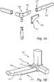
- Fig. 1B illustrates details of the corner element 100.
- the protruding connection element 102 which is a part of the corner element 100 comprises portions 104 configured to receive an adhesive 112.
- the portions 104 are for example recessed to receive an adhesive where the thickness of the adhesive is determined by the depth of the recess.
- the recess may cover part or all of the surface of one or more sides of the connection element 102.
- the recess may be formed with edges or walls so that an adhesive stay within the recess once deposited.
- the surface of the portions 104 configured to receive the adhesive may further be roughened through grinding, milling or other means in order to provide a surface roughness improving the adhesion of the adhesive to be used.
- the portions 104 of the connection element 102 may be adapted to receive an adhesive by comprising grooves, trenches, ridges, pits or the like.
- Fig. 1B further illustrates that the protruding connection element 102 comprises a ridge 110 configured to press against an inner wall of the tubular element 106 at the end portion 107 of the tubular element 106 when the tubular element 106 pressed onto the connection element 102.
- the connection element 102 may comprise a ridge 110 on one surface as illustrated in Fig. 1B , bit it may equally well be provided with ridges or similar protruding elements on multiple sides.
- the skilled person readily realizes that structures of another shape are also possible aside from a ridge.
- the ridge 110 ensures that a tight seal is formed between the connection element 112 and the tubular element 106 such that moisture and dirt is prevented from reaching the inside of the tubular element 106.
- the ridge is located at an end portion 111 of the connection element 102 closest to the final joint, i.e. the end portion 111 closest to the opening of the tubular element 106 once the two parts are assembled.
- the ridge 110 also helps to keep the two parts 100, 106 together to allow the fixation element 108 to be attached.
- the fixation element 108 is here exemplified by a plate 108 comprising holes 114 for receiving screws so that the plate 108 can be attached to the corner element 100 and the tubular element 106.
- Fig. 2 illustrates a roll-over protection structure 200 comprising the corner element 100 and attached tubular elements 106.
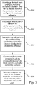
- Fig. 3 is a flow chart outlining steps of the method for assembling parts of a support structure 200 for a vehicle, and the method will be described with further reference to Figs. 1-2 .
- the method comprises providing 300 a first part 100 comprising a protruding connection element 102, wherein at least a portion of the connection element 112 is configured 104 to receive an adhesive;
- the next step comprises the providing 302 a second part 106 in the form of a tubular element configured to be connected to the first part 100.
- an adhesive 112 is deposited 304 on the portion or portions 104 of the protruding connection element configured to receive the adhesive.
- the adhesive may for example be deposited using a glue pistol, either manually or by means of an automated process. Other means of deposition are also possible.
- the first part 100 is connected 306 to the second part 106 by pressing the tubular element 106 onto the protruding connection element 102
- a fixation element 108 is attached 308 to the first part 100 and to the second part 106 to fixate the first part 100 in relation to the second part 106.
- the adhesive is advantageously an anaerobic adhesive which hardens over time in room temperature.
- the support structure 200 is thereby sufficiently held together by the ridge 110 of the connection element 102 and/or the fixation element 108 so that it can proceed directly to the next step in the assembly line where the adhesive hardens over time during further assembly.
- the parts Prior to providing the first and second parts 100, 106, the parts may have been electroplated and/or painted, or subjected to any other pre-treatment steps which are temperature sensitive.
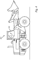
- Fig. 4 schematically illustrates a wheel loader 400 comprising a roll-over protection structure 200 according to an embodiment of the invention.
Landscapes
- Engineering & Computer Science (AREA)
- Mechanical Engineering (AREA)
- Chemical & Material Sciences (AREA)
- Combustion & Propulsion (AREA)
- Transportation (AREA)
- General Engineering & Computer Science (AREA)
- Manufacturing & Machinery (AREA)
- Mining & Mineral Resources (AREA)
- Civil Engineering (AREA)
- Structural Engineering (AREA)
- Standing Axle, Rod, Or Tube Structures Coupled By Welding, Adhesion, Or Deposition (AREA)
- Body Structure For Vehicles (AREA)
Abstract
Description
- The invention relates to a support structure for a vehicle and to a method for assembling parts of the support structure for a vehicle. In particular, the invention relates to a method for simplifying the assembly of a large support structure such as a roll-over protection structure, and to a support structure assembled using the described method.
- The invention can be applied in heavy-duty vehicles, such as construction machines, trucks, buses, and other construction equipment and vehicles. Accordingly, although the invention will be described with respect to a support structure for a construction machine such as a wheel loader, the invention is not restricted to this structure or vehicle but may also be used in other types of structures and for other types of vehicles.
- Working machines such as wheel loaders, dumpers, excavators, and the like are often operated in dangerous environments and it is therefore important to provide appropriate protection for a vehicle operator. There may for example be a risk of objects falling on the machine or of the machine tipping over in which case a vehicle operator must be well protected inside the vehicle cab.
- To provide operator safety, heavy duty vehicles often include support structures reinforcing the vehicle cab, sometimes referred to as a roll-over protection structure (ROPS). A ROPS needs to be mechanically robust and to achieve this it is often manufactured and assembled as one piece.
- However, such a support structure is relatively large and may require specialized tools and manufacturing lines for assembly. In particular, known manufacturing methods involve welding in the final assembly steps. This means that surface treatment such as corrosion protection and/or painting cannot be performed until after the full structure is assembled. Thereby, surface treatment must be performed on the final support structure as a whole, which due to its weight and size requires specialized and sometimes costly and complicated tools.
- Accordingly, in view of the above it is desirable to simplify manufacturing and assembly of large support structures for vehicles.
- An object of the invention is to provide a simplified method for assembling parts of a support structure for a vehicle.
- The object is achieved by a method according to claim 1. The method comprises providing a first part comprising a protruding connection element, wherein at least a portion of the connection element is configured to receive an adhesive; providing a second part in the form of a tubular element configured to be connected to the first part; depositing an adhesive on the portion of the protruding connection element configured to receive the adhesive; connecting first part to the second part by pressing the tubular element onto the protruding connection element; and attaching a fixation element to the first part and to the second part to fixate the first part in relation to the second part.
- In the present context, the support structure may be any structure intended to provide mechanical support in or for a vehicle. The support structure comprises at least two parts assembled by the described method. However, the support structure may consist of a large number of parts where some are assembled using the described method and where other parts are assembled using other methods.
- The present invention is based on the realization that a support structure consisting of multiple parts can be assembled by configuring a connectable tubular elements to be attached to another element using an adhesive in combination with a fixation element keeping the parts in place while allowing the adhesive to harden. An advantage of the described method is that various surface treatments of the different parts can be performed prior to assembly since no welding is required in the assembly process. This saves space in the assembly plant since there is no need for the whole of the finished support structure to undergo surface treatment.
- A further advantage of the described method is that the fixation element holds the parts together while the adhesive hardens so that the support structure can proceed immediately to the next step in the assembly line which saves time during assembly. The same advantages are present also for other support structures such as an engine hood frame or other structures where tubular elements are used.
- According to one embodiment of the invention, the portion of the connection element configured to receive an adhesive comprises a recess, and the thickness of the adhesive is defined by the depth of the recess. The thickness and location of the adhesive is thereby easily controllable, which simplifies the method.
- According to one embodiment of the invention, the protruding connection element comprises a ridge, and pressing the tubular element onto the protruding connection element comprises applying a force so that the ridge presses against an inner wall of the tubular element when the first and second parts are assembled. The ridge is configured to ensure that a tight seal is formed between the first and second parts, thereby preventing moisture and dirt from reaching the inside of the tubular element. Preferably, the ridge is arranged on an end portion of the connection element and aligned perpendicularly to the direction of insertion of the protruding connection element.
- According to one embodiment of the invention, the method comprises attaching the fixation element using an attachment method not involving heating. The fixation element may for example be attached using screws, bolts, rivets, or the like. Thereby, the parts of the support structure can be pretreated prior to assembly using pretreatment methods and steps such as electroplating or painting.
- According to one embodiment of the invention, the first element may be a corner element comprising a plurality of protruding connection elements, and the method may comprise attaching tubular elements to each of the protruding connection elements. Corner elements are used in support structures such as roll over protection structures, and by configuring the corner structures with several protruding connection elements as described, the remaining tubular elements can remaining unchanged, thus facilitating an implementation of the assembly method without the need to redesign all of the parts of the support structure. The corner element as such may be manufactured by means of welding, casting, or other methods.
- According to a second aspect of the invention, the object is achieved by a support structure for a vehicle according to claim 9. The support structure comprises: a first part comprising a protruding connection element, wherein at least a portion of the connection element is configured to receive an adhesive; a second part in the form of a tubular element, wherein the protruding connection element is arranged in an end portion of the tubular element; an adhesive arranged on the protruding connection element and configured to attach the first part to the second part; and a fixation element attached to the first part and to the second part to fixate the first part in relation to the second part. The support structure may for example be a roll over protection structure ROPS.
- Effects and features of this second aspect of the present invention are largely analogous to those described above in connection with the first aspect of the invention. Further advantages and advantageous features of the invention are disclosed in the following description and in the dependent claims.
- With reference to the appended drawings, below follows a more detailed description of embodiments of the invention cited as examples.
- In the drawings:
-
Figs. 1A-B are schematic illustrations of parts of a support structure according to an embodiment of the invention; -
Fig. 2 is a schematic illustration of a support structure according to an embodiment of the invention; -
Fig. 3 is a flow chart outlining steps of a method according to an embodiment of the invention; and -
Fig. 4 is a schematic illustration of a wheel loader comprising a support structure according to an embodiment of the invention. - In the following detailed description, various embodiments of a support structure and a method for manufacturing a support structure according to the present invention are mainly discussed with reference to a roll-over protection structure. It should be noted that this by no means limits the scope of the present invention which is equally applicable to other support structures for a vehicle.
-
Fig. 1A . is an exploded view schematically illustrating parts of a support structure andFig. 1B illustrates acorner element 100 of a support structure.Fig. 1A illustrates afirst part 100 comprising aprotruding connection element 102, wherein at least aportion 104 of the connection element is configured to receive an adhesive 112. Thefirst part 100 is here acorner element 100 of a support structure. Thesecond part 106 is atubular element 106 and theprotruding connection element 102 is configured to be inserted into anend portion 107 of thetubular element 106. The support structure further comprises afixation element 108 configured to be attached to thefirst part 100 and to thesecond part 106 to fixate thefirst part 100 in relation to thesecond part 106. -
Fig. 1B illustrates details of thecorner element 100. In particular,Fig. 1B illustrates that the protrudingconnection element 102 which is a part of thecorner element 100 comprisesportions 104 configured to receive an adhesive 112. Theportions 104 are for example recessed to receive an adhesive where the thickness of the adhesive is determined by the depth of the recess. The recess may cover part or all of the surface of one or more sides of theconnection element 102. Moreover, the recess may be formed with edges or walls so that an adhesive stay within the recess once deposited. The surface of theportions 104 configured to receive the adhesive may further be roughened through grinding, milling or other means in order to provide a surface roughness improving the adhesion of the adhesive to be used. Other types of surface treatments are also feasible for achieving desirable surface properties of theportions 104 of theconnection element 102 configured to receive the adhesive. Moreover, theportions 104 may be adapted to receive an adhesive by comprising grooves, trenches, ridges, pits or the like. -
Fig. 1B further illustrates that the protrudingconnection element 102 comprises aridge 110 configured to press against an inner wall of thetubular element 106 at theend portion 107 of thetubular element 106 when thetubular element 106 pressed onto theconnection element 102. Theconnection element 102 may comprise aridge 110 on one surface as illustrated inFig. 1B , bit it may equally well be provided with ridges or similar protruding elements on multiple sides. Moreover, the skilled person readily realizes that structures of another shape are also possible aside from a ridge. - The
ridge 110 ensures that a tight seal is formed between theconnection element 112 and thetubular element 106 such that moisture and dirt is prevented from reaching the inside of thetubular element 106. The ridge is located at anend portion 111 of theconnection element 102 closest to the final joint, i.e. theend portion 111 closest to the opening of thetubular element 106 once the two parts are assembled. Theridge 110 also helps to keep the twoparts fixation element 108 to be attached. Thefixation element 108 is here exemplified by aplate 108 comprisingholes 114 for receiving screws so that theplate 108 can be attached to thecorner element 100 and thetubular element 106. -
Fig. 2 illustrates a roll-over protection structure 200 comprising thecorner element 100 and attachedtubular elements 106. -
Fig. 3 is a flow chart outlining steps of the method for assembling parts of asupport structure 200 for a vehicle, and the method will be described with further reference toFigs. 1-2 . The method comprises providing 300 afirst part 100 comprising a protrudingconnection element 102, wherein at least a portion of theconnection element 112 is configured 104 to receive an adhesive; The next step comprises the providing 302 asecond part 106 in the form of a tubular element configured to be connected to thefirst part 100. - In the following step, an adhesive 112 is deposited 304 on the portion or
portions 104 of the protruding connection element configured to receive the adhesive. The adhesive may for example be deposited using a glue pistol, either manually or by means of an automated process. Other means of deposition are also possible. - Next, the
first part 100 is connected 306 to thesecond part 106 by pressing thetubular element 106 onto the protrudingconnection element 102 Finally, afixation element 108 is attached 308 to thefirst part 100 and to thesecond part 106 to fixate thefirst part 100 in relation to thesecond part 106. The adhesive is advantageously an anaerobic adhesive which hardens over time in room temperature. Thesupport structure 200 is thereby sufficiently held together by theridge 110 of theconnection element 102 and/or thefixation element 108 so that it can proceed directly to the next step in the assembly line where the adhesive hardens over time during further assembly. - Prior to providing the first and
second parts -
Fig. 4 schematically illustrates awheel loader 400 comprising a roll-over protection structure 200 according to an embodiment of the invention. - Even though the invention has been described with reference to specific exemplifying embodiments thereof, many different alterations, modifications and the like will become apparent for those skilled in the art. For example, many different types of structures can be assembled using the described method .Also, it should be noted that parts of the system may be omitted, interchanged or arranged in various ways, the method and support structure yet being able to perform the functionality of the present invention.
- Additionally, variations to the disclosed embodiments can be understood and effected by the skilled person in practicing the claimed invention, from a study of the drawings, the disclosure, and the appended claims. In the claims, the word "comprising" does not exclude other elements or steps, and the indefinite article "a" or "an" does not exclude a plurality. The mere fact that certain measures are recited in mutually different dependent claims does not indicate that a combination of these measured cannot be used to advantage.
Claims (15)
- A method for assembling parts of a support structure (200) for a vehicle, the method comprising:providing (300) a first part (100) comprising a protruding connection element (102), wherein at least a portion (104) of the connection element is configured to receive an adhesive;providing (302) a second part (106) in the form of a tubular element configured to be connected to the first part;depositing (304) an adhesive on the portion of the protruding connection element configured to receive the adhesive;connecting (306) first part to the second part by pressing the tubular element onto the protruding connection element; andattaching (308) a fixation element (108) to the first part and to the second part to fixate the first part in relation to the second part.
- The method according to claim 1, wherein the portion of the connection element configured (104) to receive an adhesive comprises a recess, and wherein the thickness of the adhesive is defined by the depth of the recess.
- The method according to claim 1 or 2, wherein the protruding connection element comprises a ridge (110), and wherein pressing the tubular element onto the protruding connection element comprises applying a force so that the ridge presses against an inner wall of the tubular element when the first and second parts are assembled.
- The method according to any one of the preceding claims, wherein the attaching the fixation element comprises using an attachment method not involving heating.
- The method according to any one of the preceding claims, wherein the first element is a corner element comprising a plurality of protruding connection elements, and wherein the method comprises attaching tubular elements to each of the protruding connection elements.
- The method according to any one of the preceding claims, further comprising performing pretreatment of the first and second parts.
- The method according to claim 6, wherein performing pretreatment comprises electroplating and/or painting
- The method according to any one of the preceding claims, further comprising providing the assembled parts to an assembly line and attaching additional parts to the assembled part prior to hardening of the adhesive.
- A support structure (202) for a vehicle comprising:a first part (100) comprising a protruding connection element (102), wherein at least a portion (104) of the connection element is configured to receive an adhesive (112);a second part (106) in the form of a tubular element, wherein the protruding connection element is arranged in an end portion (107) of the tubular element;an adhesive arranged on the protruding connection element and configured to attach the first part to the second part; anda fixation element (108) attached to the first part and to the second part to fixate the first part in relation to the second part.
- The support structure according to claim 9, wherein the protruding connection element comprises a ridge (110) configured to press against an inner wall of the tubular element.
- The support structure according to claim 9 or 10, wherein the support structure comprises a first element in the form of a corner element comprising a plurality of protruding connection elements and a plurality of tubular elements connected to each of the protruding connection elements.
- The support structure according to any one of claims 9 to 11, wherein the fixation element is attached by means screws or bolts.
- The support structure according to any one of claims 9 to 12, wherein the support structure is a roll over protection structure (200), ROPS.
- The support structure according to any one of claims, 9 to 13, wherein the adhesive is an anaerobic adhesive
- A vehicle (400) comprising a support structure according to anyone of claims 9 to 14.
Priority Applications (3)
| Application Number | Priority Date | Filing Date | Title |
|---|---|---|---|
| EP21153444.1A EP4032755A1 (en) | 2021-01-26 | 2021-01-26 | Support structure for a vehicle and method for assembling parts of a support structure for a vehicle |
| CN202210053848.5A CN114789706A (en) | 2021-01-26 | 2022-01-18 | Vehicle support structure and method for assembling parts of a vehicle support structure |
| US17/581,373 US20220234535A1 (en) | 2021-01-26 | 2022-01-21 | Support structure for a vehicle and method for assembling parts of a support structure for a vehicle |
Applications Claiming Priority (1)
| Application Number | Priority Date | Filing Date | Title |
|---|---|---|---|
| EP21153444.1A EP4032755A1 (en) | 2021-01-26 | 2021-01-26 | Support structure for a vehicle and method for assembling parts of a support structure for a vehicle |
Publications (1)
| Publication Number | Publication Date |
|---|---|
| EP4032755A1 true EP4032755A1 (en) | 2022-07-27 |
Family
ID=74572622
Family Applications (1)
| Application Number | Title | Priority Date | Filing Date |
|---|---|---|---|
| EP21153444.1A Withdrawn EP4032755A1 (en) | 2021-01-26 | 2021-01-26 | Support structure for a vehicle and method for assembling parts of a support structure for a vehicle |
Country Status (3)
| Country | Link |
|---|---|
| US (1) | US20220234535A1 (en) |
| EP (1) | EP4032755A1 (en) |
| CN (1) | CN114789706A (en) |
Citations (8)
| Publication number | Priority date | Publication date | Assignee | Title |
|---|---|---|---|---|
| EP0547346A1 (en) * | 1991-12-14 | 1993-06-23 | Dr.Ing.h.c. F. Porsche Aktiengesellschaft | Body for automobiles, especially for passengers |
| EP1854704A1 (en) * | 2006-05-09 | 2007-11-14 | Zephyros Inc. | Joints and a system and method of forming the joints |
| US20110158741A1 (en) * | 2009-09-22 | 2011-06-30 | Harald Knaebel | Nodal Member For A Frame Structure Nodal Assembly |
| WO2014047488A1 (en) * | 2012-09-20 | 2014-03-27 | Polaris Industries Inc. | Utiliy vehicle |
| DE202015103144U1 (en) * | 2014-06-25 | 2015-07-20 | Ford Global Technologies, Llc | Vehicle frame holder |
| EP2899100A1 (en) * | 2014-01-27 | 2015-07-29 | MAGNA STEYR Engineering AG & Co KG | Bonded joint and bonding method of two hollow profiles |
| WO2016197047A1 (en) * | 2015-06-04 | 2016-12-08 | Divergent Technologies, Inc. | Systems and methods for adhesive injection for node assembly |
| US20180086386A1 (en) * | 2016-09-28 | 2018-03-29 | Ford Global Technologies, Llc | Exoskeleton vehicle upper body structure |
Family Cites Families (20)
| Publication number | Priority date | Publication date | Assignee | Title |
|---|---|---|---|---|
| FR2001078A1 (en) * | 1969-01-13 | 1969-09-19 | Lacabanne Francis | |
| US3754315A (en) * | 1972-02-24 | 1973-08-28 | Int Harvester Co | Method and means for attaching protection structure to a vehicle frame |
| GB1585163A (en) * | 1976-06-24 | 1981-02-25 | Gkn Transmissions Ltd | Universal joint and shaft assemblies |
| DE9218668U1 (en) * | 1992-01-29 | 1995-01-05 | Sika Chemie GmbH, 70439 Stuttgart | Composite element, in particular for motor vehicle bodies, and device for the production thereof |
| US5271687A (en) * | 1992-04-03 | 1993-12-21 | Ford Motor Company | Space frame joint construction |
| US5280955A (en) * | 1992-08-28 | 1994-01-25 | Caterpillar Inc. | Construction for a rollover protection structure |
| US5458393A (en) * | 1993-08-11 | 1995-10-17 | Alumax Extrusions, Inc. | Space frame apparatus and process for the manufacture of same |
| SE503705C2 (en) * | 1994-10-25 | 1996-08-05 | Volvo Ab | Load-bearing structure for use in a vehicle body |
| FR2768386B1 (en) * | 1997-09-17 | 1999-10-29 | Camiva | METHOD AND INSERT FOR ASSEMBLING A TRANSPORT MODULE |
| US6742258B2 (en) * | 2001-11-30 | 2004-06-01 | 3M Innovative Properties Company | Method of hydroforming articles and the articles formed thereby |
| DE10329017B4 (en) * | 2003-06-27 | 2008-12-04 | Daimler Ag | Carrying structure, in particular for body structures of vehicles made of rectangular hollow sections |
| JP5534343B2 (en) * | 2010-12-21 | 2014-06-25 | 豊田合成株式会社 | Body structure |
| DE102012207901B4 (en) * | 2012-05-11 | 2021-02-25 | Bayerische Motoren Werke Aktiengesellschaft | Vehicle body with a transverse roof bow |
| ES2770053T3 (en) * | 2014-05-16 | 2020-06-30 | Divergent Tech Inc | Modular formed nodes for vehicle chassis and their methods of use |
| CN104527796A (en) * | 2015-01-07 | 2015-04-22 | 芜湖南大汽车工业有限公司 | Automobile frame structure |
| WO2017040728A1 (en) * | 2015-08-31 | 2017-03-09 | Divergent Technologies, Inc. | Systems and methods for vehicle subassembly and fabrication |
| JP6625031B2 (en) * | 2016-09-28 | 2019-12-25 | 株式会社神戸製鋼所 | Member joining method |
| US10065694B1 (en) * | 2017-05-18 | 2018-09-04 | Honda Motor Co., Ltd. | Vehicle assembly |
| KR102586882B1 (en) * | 2018-03-09 | 2023-10-10 | 에이치디현대인프라코어 주식회사 | Canopy assembly of construction machinery |
| EP3782879B1 (en) * | 2019-08-22 | 2021-12-15 | C.R.F. Società Consortile per Azioni | Motor-vehicle lattice frame |
-
2021
- 2021-01-26 EP EP21153444.1A patent/EP4032755A1/en not_active Withdrawn
-
2022
- 2022-01-18 CN CN202210053848.5A patent/CN114789706A/en active Pending
- 2022-01-21 US US17/581,373 patent/US20220234535A1/en not_active Abandoned
Patent Citations (8)
| Publication number | Priority date | Publication date | Assignee | Title |
|---|---|---|---|---|
| EP0547346A1 (en) * | 1991-12-14 | 1993-06-23 | Dr.Ing.h.c. F. Porsche Aktiengesellschaft | Body for automobiles, especially for passengers |
| EP1854704A1 (en) * | 2006-05-09 | 2007-11-14 | Zephyros Inc. | Joints and a system and method of forming the joints |
| US20110158741A1 (en) * | 2009-09-22 | 2011-06-30 | Harald Knaebel | Nodal Member For A Frame Structure Nodal Assembly |
| WO2014047488A1 (en) * | 2012-09-20 | 2014-03-27 | Polaris Industries Inc. | Utiliy vehicle |
| EP2899100A1 (en) * | 2014-01-27 | 2015-07-29 | MAGNA STEYR Engineering AG & Co KG | Bonded joint and bonding method of two hollow profiles |
| DE202015103144U1 (en) * | 2014-06-25 | 2015-07-20 | Ford Global Technologies, Llc | Vehicle frame holder |
| WO2016197047A1 (en) * | 2015-06-04 | 2016-12-08 | Divergent Technologies, Inc. | Systems and methods for adhesive injection for node assembly |
| US20180086386A1 (en) * | 2016-09-28 | 2018-03-29 | Ford Global Technologies, Llc | Exoskeleton vehicle upper body structure |
Also Published As
| Publication number | Publication date |
|---|---|
| US20220234535A1 (en) | 2022-07-28 |
| CN114789706A (en) | 2022-07-26 |
Similar Documents
| Publication | Publication Date | Title |
|---|---|---|
| KR102048606B1 (en) | Vehicle bodywork and method of constructing the vehicle | |
| US20200247204A1 (en) | Motor vehicle control arm | |
| WO2010100225A1 (en) | Method for fastening a component to a plastic part of a motor vehicle using the torsional ultrasonic welding method | |
| US20050225111A1 (en) | Corrosion-resistant body for utility vehicle | |
| EP1621384A1 (en) | Rear vehicle door | |
| DE10029411A1 (en) | Plastic-metal composite component and method for its production | |
| DE102009009112A1 (en) | Structural component for motor vehicle, particularly B-column, side sill, or bumper cross beam, comprises base body made of sheet metal, and is partially provided with reinforcement element | |
| EP1055787A1 (en) | Adjustable mounting plate | |
| CN114258354B (en) | Overmolded component reinforcement bracket | |
| US20220234535A1 (en) | Support structure for a vehicle and method for assembling parts of a support structure for a vehicle | |
| US20110209814A1 (en) | Method of and apparatus for weld-bonding workpieces | |
| WO2005075281A1 (en) | Joining area for attaching an add-on piece to a vehicle body | |
| WO2023274650A1 (en) | Unfinished component for a body of a derivative which is derived from a base vehicle, and method for producing said unfinished component | |
| DE10333678B4 (en) | Method for producing a section-wise reinforced tubular support made of metal, in particular for supporting structures in motor vehicles | |
| DE10351446B4 (en) | threaded plate | |
| SE1950545A1 (en) | Corner patch | |
| CN209535227U (en) | Body structure for automobile | |
| DE102012009009A1 (en) | Method for mounting roof element on roof frame element of motor vehicle e.g. passenger car, involves fastening roof rack to roof element by receiving element in final assembly position through receiving opening of pre-fixing element | |
| DE102010035750A1 (en) | Lock arrangement for e.g. side door of motor car, has form-fit elements and adhesive bond provided between lock and component of door and/or striker and component of vehicle body, where adhesive bond is provided to receive normal load | |
| EP1882625B1 (en) | Car bodywork with aluminium diecast spring support coated with cataphoretic paint | |
| DE102015217524B4 (en) | Body structure for a two-lane motor vehicle | |
| DE102015111326A1 (en) | Battery housing part for a traction battery of a vehicle, method for manufacturing a battery case and vehicle with a battery housing part | |
| DE102010048256A1 (en) | Retaining flange for fastening hydraulic directional valve block at e.g. counterweight forklift truck, has integrated attaching unit for attaching additional component or fastening component of module provided with directional valve block | |
| DE102006050424A1 (en) | Roof antenna for mounting on a vehicle roof of a vehicle with a central attachment point between a hood and an intermediate hood | |
| KR20050006918A (en) | Hemming progress |
Legal Events
| Date | Code | Title | Description |
|---|---|---|---|
| PUAI | Public reference made under article 153(3) epc to a published international application that has entered the european phase |
Free format text: ORIGINAL CODE: 0009012 |
|
| STAA | Information on the status of an ep patent application or granted ep patent |
Free format text: STATUS: THE APPLICATION HAS BEEN PUBLISHED |
|
| AK | Designated contracting states |
Kind code of ref document: A1 Designated state(s): AL AT BE BG CH CY CZ DE DK EE ES FI FR GB GR HR HU IE IS IT LI LT LU LV MC MK MT NL NO PL PT RO RS SE SI SK SM TR |
|
| STAA | Information on the status of an ep patent application or granted ep patent |
Free format text: STATUS: REQUEST FOR EXAMINATION WAS MADE |
|
| 17P | Request for examination filed |
Effective date: 20230117 |
|
| RBV | Designated contracting states (corrected) |
Designated state(s): AL AT BE BG CH CY CZ DE DK EE ES FI FR GB GR HR HU IE IS IT LI LT LU LV MC MK MT NL NO PL PT RO RS SE SI SK SM TR |
|
| STAA | Information on the status of an ep patent application or granted ep patent |
Free format text: STATUS: EXAMINATION IS IN PROGRESS |
|
| 17Q | First examination report despatched |
Effective date: 20240626 |
|
| STAA | Information on the status of an ep patent application or granted ep patent |
Free format text: STATUS: THE APPLICATION IS DEEMED TO BE WITHDRAWN |
|
| 18D | Application deemed to be withdrawn |
Effective date: 20241029 |