EP4032721A1 - Writing instruments and methods thereof - Google Patents
Writing instruments and methods thereof Download PDFInfo
- Publication number
- EP4032721A1 EP4032721A1 EP21305098.2A EP21305098A EP4032721A1 EP 4032721 A1 EP4032721 A1 EP 4032721A1 EP 21305098 A EP21305098 A EP 21305098A EP 4032721 A1 EP4032721 A1 EP 4032721A1
- Authority
- EP
- European Patent Office
- Prior art keywords
- writing
- retainer
- writing instrument
- housing member
- writing element
- Prior art date
- Legal status (The legal status is an assumption and is not a legal conclusion. Google has not performed a legal analysis and makes no representation as to the accuracy of the status listed.)
- Withdrawn
Links
- 238000000034 method Methods 0.000 title claims description 11
- 230000007246 mechanism Effects 0.000 description 5
- 239000011148 porous material Substances 0.000 description 5
- 239000012528 membrane Substances 0.000 description 4
- 238000012986 modification Methods 0.000 description 3
- 230000004048 modification Effects 0.000 description 3
- 238000010276 construction Methods 0.000 description 2
- 230000008878 coupling Effects 0.000 description 2
- 238000010168 coupling process Methods 0.000 description 2
- 238000005859 coupling reaction Methods 0.000 description 2
- 230000003993 interaction Effects 0.000 description 2
- 239000003550 marker Substances 0.000 description 2
- 239000000463 material Substances 0.000 description 2
- 230000004888 barrier function Effects 0.000 description 1
- 239000003610 charcoal Substances 0.000 description 1
- 238000006073 displacement reaction Methods 0.000 description 1
- 238000000605 extraction Methods 0.000 description 1
- 239000012530 fluid Substances 0.000 description 1
- 238000004519 manufacturing process Methods 0.000 description 1
Images




Classifications
-
- B—PERFORMING OPERATIONS; TRANSPORTING
- B43—WRITING OR DRAWING IMPLEMENTS; BUREAU ACCESSORIES
- B43K—IMPLEMENTS FOR WRITING OR DRAWING
- B43K23/00—Holders or connectors for writing implements; Means for protecting the writing-points
- B43K23/08—Protecting means, e.g. caps
-
- B—PERFORMING OPERATIONS; TRANSPORTING
- B43—WRITING OR DRAWING IMPLEMENTS; BUREAU ACCESSORIES
- B43K—IMPLEMENTS FOR WRITING OR DRAWING
- B43K27/00—Multiple-point writing implements, e.g. multicolour; Combinations of writing implements
- B43K27/08—Combinations of pens
-
- B—PERFORMING OPERATIONS; TRANSPORTING
- B43—WRITING OR DRAWING IMPLEMENTS; BUREAU ACCESSORIES
- B43K—IMPLEMENTS FOR WRITING OR DRAWING
- B43K3/00—Nib holders
- B43K3/04—Nib holders with retractable nibs
Definitions
- the present disclosure relates generally to the field of writing instruments. More specifically, the present disclosure relates to a writing instrument configured to improve removal of one or more component which may be disposed within the writing instrument.
- a typical writing instrument may include one or more writing element disposed within a housing.
- a writing element may include a ballpoint pen, a highlighter, a marker, a pencil, and/or the like.
- the writing element may be removable, so as to allow the writing element and/or a cartridge thereof to be replaceable. Additionally, the writing element may be mechanically displaceable, so that the writing element and/or a writing tip thereof may be moved to a position outside of the housing.
- removing the writing element may require that a user directly grasp a cartridge of a highlighter in order to remove the writing element from the housing. Directly grasping the cartridge of the highlighter may result in a hand of the user coming into direct contact with ink of the highlighter, which may create a messy situation. Additionally, removing the writing element may also include removal of a mechanical component which allows for mechanical displacement of the writing element, such as a spring and/or the like. Removal of the mechanical component may increase a risk of losing the mechanical component, which may result in the writing instrument no longer functioning properly.
- a writing instrument extends along an axis between a first end and a second end, and comprises a first housing member configured to surround at least a portion of a writing element, a second housing member configured to surround at least a portion of the writing element, a retainer configured to be received by the first housing member, and the retainer configured to engage the writing element, and wherein, engagement of the writing element by the retainer allows the writing element to be withdrawn from the second housing member when the retainer is moved axially away from the second housing member.
- the retainer is configured to be received between the first housing member and the writing element.
- a gap is formed between the retainer and the first housing member when the retainer is received by the first housing member.
- the retainer includes a first engagement member
- the writing element includes a second engagement member
- the first engagement member is configured to engage the second engagement member
- the first engagement member includes a recess configured to form the gap between the retainer and the first housing member.
- the first engagement member is capable of movement within the gap formed between the retainer and the first housing member.
- the first engagement member includes a hook projecting radially inwardly
- the second engagement member includes a shoulder projecting radially outwardly
- the hook is configured to abut the shoulder
- one or more of the hook and the shoulder includes a ramped surface.
- the hook projects from an axially extending arm, and the axially extending arm is elastically deformable.
- the retainer includes a plurality of engagement members, an opening having a first diameter is formed between the plurality of engagement members, and the second engagement member of the writing element includes a second diameter greater than the first diameter of the opening.
- the retainer includes a connection member configured to form a connection with the first housing member.
- the first engagement member of the retainer and the connection member of the retainer are configured to be radially offset from each other about the axis of the writing instrument.
- connection member is a radially-projecting rib.
- the first housing member is configured to engage a bias member.
- the writing instrument includes a second writing element.
- a method for removing a writing element from a writing instrument comprises providing the writing instrument according to any aspect disclosed herein, and moving the retainer axially away from the second housing member to withdraw the writing element from the writing instrument.
- the writing instrument and the method are configured to improve removal of a writing element from the writing instrument in a hassle-free and convenient manner.
- first the terms “first,” “second,” etc. may be used herein to describe various elements, components, regions, layers, sections, and/or parameters, these elements, components, regions, layers, sections, and/or parameters should not be limited by these terms. These terms are only used to distinguish one element, component, region, layer, or section from another region, layer, or section. Thus, a first element, component, region, layer, or section discussed herein could be termed a second element, component, region, layer, or section without departing from the teachings of the present disclosure.
- a writing instrument 10 configured to improve removal of one or more component of the writing instrument 10 is provided.
- the term "writing instrument” as used herein may be understood to be a tool used to produce writing and/or drawing (e.g. figures, characters, lines, forms, and/or the like).
- the writing instrument 10 extends from a first end 12 to a second end 14 along an axis A-A.
- the writing instrument 10 includes a tubular housing 20 having a first housing member 22 configured to extend from the first end 12 of the writing instrument 10 toward the second end 14 of the writing instrument 10 and a second housing member 24 configured to extend from the second end 14 of the writing instrument 10 toward the first end 12 of the writing instrument 10.
- the writing instrument 10 also includes a writing element 40, a retainer 60 configured to facilitate removal of the writing element 40 from the housing 20 of the writing instrument 10, and a bias member 90 (see Figures 2-3 ) configured to mechanically displace the writing element 40 by providing a return force on the writing element 40 when the writing element 40 is retracted within the housing 20.
- the bias member 90 is a coil spring; however, it is contemplated that other bias members may be compatible with the writing instrument 10.
- the writing instrument 10 may also include a driving mechanism 95 configured for retraction and extraction of the writing element 40 to and from the writing instrument 10, respectively.
- the driving mechanism 95 is positioned within the housing 20, adjacent the second end 14 of the housing 20, and may be actuated by twisting a portion of the writing instrument 10 and/or a component connected thereto.
- the driving mechanism 95 may include a cam and a cam follower.
- alternative driving mechanisms may be compatible with the writing instrument 10, such as a driving mechanism including a push-button actuator.
- the housing 20, the writing element 40, the retainer 60, and the bias member 90 are all configured to extend along the axis A-A of the writing instrument 10.
- the housing 20, the writing element 40, the retainer 60, and the bias member 90 of the writing instrument 10 are each configured to include an axis which is common to and/or the same as the axis A-A of the writing instrument 10.
- the axis of each of the housing 20, the writing element 40, the retainer 60, and the bias member 90 of the writing instrument 10 will also be referred to herein as "the axis A-A.”
- writing element may be understood to be a component of the writing instrument 10 configured to hold and transfer a fluid-based writing medium (not shown), such as ink, to a writing surface (not shown) (e.g. a highlighter, ballpoint pen, rollerball pen, fountain pen, marker, felt-tipped pen, and/or the like. Additionally or alternatively, the term “writing element” may be understood to be a component of the writing instrument 10 configured to hold and transfer a solid-type writing medium (not shown) to a writing surface (e.g. a pencil, stylus, chalk, charcoal, lead, and/or the like.
- a fluid-based writing medium such as ink
- a writing surface e.g. a highlighter, ballpoint pen, rollerball pen, fountain pen, marker, felt-tipped pen, and/or the like.
- writing element may be understood to be a component of the writing instrument 10 configured to hold and transfer a solid-type writing medium (not shown) to a writing surface (e.g. a pencil, stylus, chalk
- the writing element 40 is a highlighter. It is contemplated that the term "highlighter” as used herein may be understood to be a writing element 40 configured to overlay brightly colored transparent ink to mark select text on a writing surface.
- the writing instrument 10 may include a second writing element 16, which includes an additional writing medium (not shown).
- the second writing element 16 may be a ballpoint pen including a ballpoint tip and an ink cartridge. The second writing element 16 is configured to be received within an opening of the writing element 40. To this end, the second writing element 16 has a diameter that is less than an internal diameter of the writing element 40. Additionally, to this end, the writing element 40 is formed as a hollow cylinder.
- the second writing element 16 may not be retractable, as the writing element 40 is. Additionally, the second writing element 16 may be replaceable and may be removed by a user when the user removes the first housing member 22, the writing element 40, and the retainer 60 from the second housing member 24, as illustrated by Figures 1A-1B and as will be discussed further herein.
- the writing element 40 includes a filler-type writing medium cartridge (also referred to herein as a "reservoir”) 42 (see Figures 1A , 4 , and 8 ), which is a writing medium cartridge 42 that is constructed of a porous material (not shown) for holding a writing medium, such as within the pores of the writing medium cartridge 42, without allowing the writing medium to flow freely, yet allowing the writing medium to be extracted, such as by a wick using capillary forces, for application to a writing surface.
- the writing element 40 may also include a writing tip 44 (also referred to herein as a "nib") configured to transfer the writing medium from the writing medium cartridge 42 to a writing surface.
- the writing tip 44 may be constructed of the same or substantially similar porous material as the writing medium cartridge 42.
- the writing medium cartridge 42 and the writing tip 44 are exposed to an interior of the housing 20 and/or the surrounding environment when removed from the housing 20.
- the one or more component contemplated for removal from the writing instrument 10 is the writing element 40 of the writing instrument 10.
- the porosity of the writing element 40 in combination with exposure of the porous material of the writing element 40 to a user removing the writing element 40 from the writing instrument 10, creates a potential for the writing medium to come in direct contact with a hand of a user and/or other unintended surfaces. Accordingly, interaction between the retainer 60 and the writing element 40, and between the retainer 60 and the first housing member 22 of the housing 20, are configured to allow for proper handling and/or removal of the writing element 40 from the writing instrument 10 to reduce and/or eliminate direct contact between a user and the writing medium cartridge 42.
- the housing 20 of the writing instrument 10 includes the first housing member 22 and the second housing member 24.
- the first housing member 22 is configured to mate with the second housing member 24 to form the housing 20 of the writing instrument 10.
- the first housing member 22 and the second housing member 24 are configured to mate via a threaded connection.
- the first housing member 22 and the second housing member 24 are configured to be unscrewed from each other in order to remove and/or replace the writing element 40.
- the first housing member 22 is configured to define a first cavity 26 and the second housing member 24 is configured to define a second cavity 28. In this manner, the first housing member 22 is configured to receive and/or surround at least a portion of the writing element 40.
- the second housing member 24 is also configured to surround at least a portion of the writing element 40. Additionally, the first housing member 22 is configured to receive and/or surround the retainer 60 and the bias member 90. In the disclosed embodiment, the bias member 90 is coupled to the first housing member 22. Particularly, the bias member 90 is press-fit within the first housing member 22. Coupling the bias member 90 to the first housing member 22 reduces a risk of losing the bias member 90 during removal and/or replacement of the writing element 40 from and/or into the second housing member 24. Referring to Figures 6A-6C , in the disclosed embodiment, the first housing member 22 includes a cover 30 configured to mate with a support 32. However, it is contemplated that the cover 30 and the support 32 may be constructed integrally as one component.
- the retainer 60 of the writing instrument 10 is configured to be received in the housing 20.
- the retainer 60 of the writing instrument 10 is configured to be received within the first housing member 22.
- the retainer 60 is configured to form a press-fit connection with the first housing member 22.
- the retainer 60 includes a body 62 and one or more connection member 64 extending along the body 62, which is configured to form the press-fit connection between the retainer 60 and the first housing member 22.
- the retainer 60 includes a plurality of the connection members 64.
- the connection member 64 is in the form of a radially-projecting rib.
- connection member 64 may be configured to couple with a second connection member 34, which may be included by the first housing member 22 (see Figures 6B-6C ).
- first housing member 22 may include a plurality of second connection members 34 complimentary to the plurality of connection members 64 of the retainer 60; however, the plurality of second connection members 34 will be referred to herein as "the second connection member 34" unless reference to the plurality of second connection members 34 is otherwise necessary.
- the second connection member 34 of the first housing member 22 may be in the form of a groove configured to receive and/or couple with the connection member 64.
- connection member 64 of the retainer 60 may be in the form of the groove and the second connection member 34 of the first housing member 22 may be in the form of a radially-projecting rib.
- the press-fit connection or the coupling between the retainer 60 and the first housing member 22 allows for a user to move the retainer 60 axially away from the second housing member 24 by grasping and pulling the first housing member 22 axially away from the second housing member 24 during removal and/or replacement of the writing element 40.
- the retainer 60 is configured to engage the writing element 40.
- the retainer 60 includes a first engagement member 68 extending from the body 62.
- the retainer 60 may include a plurality of first engagement members 68 extending from the body 62; however, the plurality of first engagement members 68 will be referred to herein as "the first engagement member 68" unless reference to the plurality of first engagement members 68 is otherwise necessary.
- the first engagement member 68 of the retainer 60 is configured to engage a second engagement member 48 (see Figures 3-5 and 8 ) included by the writing element 40.
- the first engagement member includes an arm 70 extending axially from the body 62.
- the first engagement 68 member includes a hook 72 projecting radially inwardly from the arm 70, which is configured to engage the second engagement member 48 of the writing element 40.
- the terms “inwardly” and “outwardly” as used herein may be understood with reference to the axis A-A. As such, “inwardly” may be understood as a direction extending transversely with respect to the axis A-A, toward the axis A-A, and “outwardly” may be understood as a direction extending transversely with respect to the axis A-A, away from the axis A-A.
- the hook 72 may include a ramped surface 74 to provide clearance for the second engagement member 48 of the writing element 40 when the writing element 40 is inserted within the retainer 60 and/or when the writing element 40 is removed from the retainer 60.
- an opening 78 is formed between the plurality of first engagement members 68 of the retainer 60.
- the opening 78 is formed between the hooks 72 of the plurality of first engagement members 68 of the retainer 60.
- the second engagement member 48 of the writing element 40 is configured to be inserted through the opening 78 and/or to be withdrawn through the opening 78 so that the writing element 40 may be engaged with the retainer 60 and/or so that the writing element 40 may be disengaged with the retainer 60, respectively.
- the opening 78 includes a first diameter D 1 which is smaller than a second diameter D 2 of the second engagement member 48. The difference in diameters allows the writing element 40 to be engaged and/or secured within the retainer 60.
- the second engagement member 48 of the writing element 40 must exert a force and/or apply pressure upon the first engagement member 68 in order to be inserted through the opening 78 and/or to be withdrawn through the opening 78.
- the second engagement member 48 of the writing element 40 must exert a force and/or apply pressure upon the hook 72 of the first engagement member 68 in order to be inserted through the opening 78 and/or to be withdrawn through the opening 78.
- the first engagement member 68 is elastically deformable.
- the arm 70 of the first engagement member 68 is elastically deformable. As such, the first engagement member 68 is capable of movement.
- the first engagement member 68 is capable of movement in a direction away from the axis A-A of the retainer 60. In the same manner, the first engagement member 68 is capable of movement in a direction toward the axis A-A of the retainer 60. Deformation and/or movement of the first engagement member 68 allows for the second engagement member 48 of the writing element 40 to be inserted through the opening 78 and received within the retainer 60, such that the second engagement member 48 of the writing element 40 may be engaged by the first engagement member 68 of the retainer 60.
- first engagement member 68 allows for the second engagement member 48 of the writing element 40 to be withdrawn through the opening 78 and from the retainer 60, such that the second engagement member 48 of the writing element 40 may be disengaged from the first engagement member 68 of the retainer 60.
- the first engagement member 68 includes a recess 76 configured to allow for the deformation and/or movement of the first engagement member 68 when the retainer 60 is positioned within and/or coupled to the first housing member 22.
- the recess 76 is formed at an exterior surface of the first engagement member 68.
- the exterior surface of the first engagement member 68 may be stepped in order to form the recess 76.
- the exterior surface of the first engagement member 68 may include a single surface and/or a slope which forms the recess 76.
- the recess 76 of the first engagement member 68 is configured to form a gap 80 between the retainer 60 and the first housing member 22 when the retainer 60 is positioned within and/or coupled to the first housing member 22.
- the recess 76 of the first engagement member 68 is configured to form the gap 80 between the first engagement member 68 of the retainer 60 and the first housing member 22 when the retainer 60 is positioned within and/or coupled to the first housing member 22.
- the gap 80 formed between the retainer 60 and the first housing member 22 creates space for the movement and/or deformation of the first engagement member 68.
- the gap 80 formed between the retainer 60 and the first housing member 22 creates space for the movement and/or deformation of the first engagement member 68 in the direction away from the axis A-A of the retainer 60.
- the first engagement member 68 and the connection member 64 of the retainer are radially offset from each other about the axis A-A, so that the gap 80 is formed for movement and/or deformation of the first engagement member 68, while the retainer 60 is also capable surface-to-surface interaction with the first housing member 22 to directly connect and/or couple to the first housing member 22.
- the first engagement member 68 may move within the gap 80 in order to allow the second engagement member 48 of the writing element 40 to pass through the opening 78 of the retainer 60 and engage with the first engagement member 68 the retainer 60. Additionally, in this manner, the first engagement member 68 may move within the gap 80 in order to allow the second engagement member 48 of the writing element 40 to be disengaged with the first engagement member 68 of the retainer and withdrawn from the retainer 60.
- the writing element 40 is configured to be received in and extend throughout the housing 20.
- the writing tip 44 is configured to be received in and extend within the first cavity 26 of the first housing member 22 and the writing medium cartridge 42 is configured to be received in and extend within the second cavity 28 of the second housing.
- the writing element 40 is configured to be engaged by the retainer 60.
- the writing element 40 includes the second engagement member 48 which is configured to be engaged by the first engagement member 68 of the retainer 60.
- the second engagement member 48 of the writing element 40 is configured to apply a force and/or pressure upon the first engagement member 68 of the retainer 60 in order to move the first engagement member 68 away from the axis A-A of the retainer 60 and into the gap 80 between the retainer 60 and the first housing member 22.
- the second engagement member 48 is positioned on the writing tip 44 of the writing element 40.
- the second engagement member 48 includes a shoulder 50 projecting radially outwardly from the writing tip 44.
- the second engagement member 48 includes an annular shoulder 50; however, it is contemplated that other geometries may be compatible for engagement with the first engagement member 68 of the retainer 60.
- the shoulder 50 of the second engagement member 48 may include a ramped surface 52 to provide clearance for the second engagement member 48 of the writing element 40 when the writing element 40 is inserted within the retainer 60 and/or when the writing element 40 is removed from the retainer 60.
- the hook 72 of the first engagement member 68 of the retainer 60 is configured to abut the shoulder 50 of the second engagement member 48 of the writing element 40 in order to form the engagement between the first engagement member 68 and the second engagement member 48, when the second engagement member 48 is inserted past the first engagement member 68.
- the writing element 40 remains engaged by the retainer 60 and/or the first housing member 22 when the first housing member 22 is unscrewed and moved axially away from the second housing member 24.
- a user may handle the writing element 40 during removal from and/or replacement into the second housing member 24 by grasping the first housing member 22.
- the writing medium cartridge 42 may include a grip 54 constructed of a non-porous material and/or configured to avoid contact with the writing medium. Additionally or alternatively, the writing medium cartridge 42 may include a membrane 46 configured to provide an impermeable barrier to the writing medium, such as a plastic membrane 46, at an outer surface of the writing medium cartridge 42. As such, the membrane 46 is configured to prevent leakage of the writing medium from the writing medium cartridge 42.
- the grip 54 may be configured to be grasped by a user once the writing element 40 is removed from the second housing member 24, in order for the user to pull the writing element 40 out of engagement with the retainer 60.
- the membrane 46 may be configured to be grasped by a user once the writing element 40 is removed from the second housing member 24, in order for the user to pull the writing element 40 out of engagement with the retainer 60. Accordingly, direct contact between a hand of a user and/or other unintended surfaces and the writing medium of the writing element 40 is reduced and/or avoided to allow for hassle-free and convenient handling of the writing element 40.
Landscapes
- Pens And Brushes (AREA)
Abstract
A writing instrument (10) comprising a first housing member (22) configured to surround at least a portion of a writing element (40), a second housing member (24) configured to surround at least a portion of the writing element (40), a retainer (60) configured to be received by the first housing member (22), and the retainer (60) configured to engage the writing element (40), and wherein, engagement of the writing element (40) by the retainer (60) allows the writing element (40) to be withdrawn from the second housing member (24) when the retainer (60) is moved axially away from the second housing member (24).
Description
- The present disclosure relates generally to the field of writing instruments. More specifically, the present disclosure relates to a writing instrument configured to improve removal of one or more component which may be disposed within the writing instrument.
- A typical writing instrument may include one or more writing element disposed within a housing. Examples of a writing element may include a ballpoint pen, a highlighter, a marker, a pencil, and/or the like. The writing element may be removable, so as to allow the writing element and/or a cartridge thereof to be replaceable. Additionally, the writing element may be mechanically displaceable, so that the writing element and/or a writing tip thereof may be moved to a position outside of the housing.
- In currently available writing instruments which include a highlighter as the writing element, removing the writing element may require that a user directly grasp a cartridge of a highlighter in order to remove the writing element from the housing. Directly grasping the cartridge of the highlighter may result in a hand of the user coming into direct contact with ink of the highlighter, which may create a messy situation. Additionally, removing the writing element may also include removal of a mechanical component which allows for mechanical displacement of the writing element, such as a spring and/or the like. Removal of the mechanical component may increase a risk of losing the mechanical component, which may result in the writing instrument no longer functioning properly.
- It is desirable to provide a writing instrument which includes structures and/or relationships configured to improve removal of a writing element from the writing instrument in a hassle-free and convenient manner.
- According to aspects of the disclosure, a writing instrument is provided. The writing instrument extends along an axis between a first end and a second end, and comprises a first housing member configured to surround at least a portion of a writing element, a second housing member configured to surround at least a portion of the writing element, a retainer configured to be received by the first housing member, and the retainer configured to engage the writing element, and wherein, engagement of the writing element by the retainer allows the writing element to be withdrawn from the second housing member when the retainer is moved axially away from the second housing member.
- According to aspects of the disclosure, the retainer is configured to be received between the first housing member and the writing element.
- According to aspects of the disclosure, a gap is formed between the retainer and the first housing member when the retainer is received by the first housing member.
- According to aspects of the disclosure, the retainer includes a first engagement member, the writing element includes a second engagement member, and the first engagement member is configured to engage the second engagement member.
- According to aspects of the disclosure, the first engagement member includes a recess configured to form the gap between the retainer and the first housing member.
- According to aspects of the disclosure, the first engagement member is capable of movement within the gap formed between the retainer and the first housing member.
- According to aspects of the disclosure, the first engagement member includes a hook projecting radially inwardly, the second engagement member includes a shoulder projecting radially outwardly, and the hook is configured to abut the shoulder.
- According to aspects of the disclosure, one or more of the hook and the shoulder includes a ramped surface.
- According to aspects of the disclosure, the hook projects from an axially extending arm, and the axially extending arm is elastically deformable.
- According to aspects of the disclosure, the retainer includes a plurality of engagement members, an opening having a first diameter is formed between the plurality of engagement members, and the second engagement member of the writing element includes a second diameter greater than the first diameter of the opening.
- According to aspects of the disclosure, the retainer includes a connection member configured to form a connection with the first housing member.
- According to aspects of the disclosure, the first engagement member of the retainer and the connection member of the retainer are configured to be radially offset from each other about the axis of the writing instrument.
- According to aspects of the disclosure, the connection member is a radially-projecting rib.
- According to aspects of the disclosure, the first housing member is configured to engage a bias member.
- According to aspects of the disclosure, the writing instrument includes a second writing element.
- According to aspects of the disclosure, a method for removing a writing element from a writing instrument is provided. The method comprises providing the writing instrument according to any aspect disclosed herein, and moving the retainer axially away from the second housing member to withdraw the writing element from the writing instrument.
- In the manner described and according to aspects illustrated herein, the writing instrument and the method are configured to improve removal of a writing element from the writing instrument in a hassle-free and convenient manner.
- Aspects of an embodiment will be described in reference to the drawings, where like numerals reflect like elements:
-
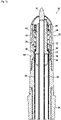
Figure 1A is a cross-sectional view of a writing instrument according to aspects of the disclosure, taken along an axis A-A, and shown without a second housing member of a housing of the writing instrument; -
Figure 1B is a cross-sectional view of the second housing member of the housing of the writing instrument according toFigure 1A , taken along the axis A-A; -
Figure 2 is a partial exploded view of the writing instrument according toFigures 1A-1B ; -
Figure 3 is a partial cross-sectional view of the writing instrument according toFigures 1A-1B , taken along the axis A-A; -
Figure 4 is a partial cross-sectional view of the writing instrument according toFigures 1A-1B , taken along the axis A-A, with emphasis on a retainer, a writing element, and a first housing member of the writing instrument according toFigures 1A-1B ; -
Figure 5 is a partial cross-sectional view of the writing instrument according toFigures 1A-1B , taken along the axis A-A, with emphasis on the retainer and the writing element of the writing instrument according toFigures 1A-1B ; -
Figure 6A is a perspective view of the first housing member of the housing of the writing instrument according toFigures 1A-1B ; -
Figure 6B is a cross-sectional view of the first housing member according toFigure 6A , taken along the line VIB; -
Figure 6C is an exploded cross-sectional view of the first housing member according toFigure 6A , taken along the line VIB; -
Figure 7A is a perspective view of the retainer of the writing instrument according toFigures 1A-1B ; -
Figure 7B is a cross-sectional view of the retainer of the writing instrument according toFigure 7A ; and -
Figure 8 is a perspective view of a writing tip of the writing element of the writing instrument according toFigures 1A-1B . - An embodiment of a writing instrument and a method of removing a writing element from a writing instrument according to aspects of the disclosure will now be described with reference to
Figures 1A-8 . Like numerals represent like parts, and the writing instrument will generally be referred to by thereference numeral 10. Although thewriting instrument 10 is described with reference to specific examples, it should be understood that modifications and changes may be made to these examples without going beyond the general scope as defined by the claims. In particular, individual characteristics of the various embodiments shown and/or mentioned herein may be combined in additional embodiments. Consequently, the description and the drawings should be considered in a sense that is illustrative rather than restrictive. The Figures, which are not necessarily to scale, depict illustrative aspects and are not intended to limit the scope of the disclosure. The illustrative aspects depicted are intended only as exemplary. - The term "exemplary" is used in the sense of "example," rather than "ideal." While aspects of the disclosure are amenable to various modifications and alternative forms, specifics thereof have been shown by way of example in the drawings and will be described in detail. It should be understood, however, that the intention is not to limit aspects of the disclosure to the particular embodiment(s) described. On the contrary, the intention of this disclosure is to cover all modifications, equivalents, and alternatives falling within the scope of the disclosure.
- Various materials, methods of construction and methods of fastening will be discussed in the context of the disclosed embodiment(s). Those skilled in the art will recognize known substitutes for the materials, construction methods, and fastening methods, all of which are contemplated as compatible with the disclosed embodiment(s) and are intended to be encompassed by the appended claims.
- As used in this disclosure and the appended claims, the singular forms "a," "an," and "the" include plural referents unless the content clearly dictates otherwise. As used in this disclosure and the appended claims, the term "or" is generally employed in its sense including "and/or" unless the content clearly dictates otherwise.
- Throughout the description, including the claims, the terms "comprising a," "including a," and "having a" should be understood as being synonymous with "comprising one or more," "including one or more," and "having one or more" unless otherwise stated. In addition, any range set forth in the description, including the claims should be understood as including its end value(s) unless otherwise stated. Specific values for described elements should be understood to be within accepted manufacturing or industry tolerances known to one of skill in the art, and any use of the terms "substantially," "approximately," and "generally" should be understood to mean falling within such accepted tolerances.
- When an element or feature is referred to herein as being "on," "engaged to," "connected to," or "coupled to" another element or feature, it may be directly on, engaged, connected, or coupled to the other element or feature, or intervening elements or features may be present. In contrast, when an element or feature is referred to as being "directly on," "directly engaged to," "directly connected to," or "directly coupled to" another element or feature, there may be no intervening elements or features present. Other words used to describe the relationship between elements or features should be interpreted in a like fashion (e.g., "between" versus "directly between," "adjacent" versus "directly adjacent," etc.).
- Spatially relative terms, such as "top," "bottom," "middle," "inner," "outer," "beneath," "below," "lower," "above," "upper," and the like, may be used herein for ease of description to describe one element or feature's relationship to another element(s) or feature(s) as illustrated in the drawings. Spatially relative terms may be intended to encompass different orientations of a device in use or operation in addition to the orientation depicted in the drawings. For example, if the device in the drawings is turned over, elements described as "below" or "beneath" other elements or features would then be oriented "above" the other elements or features. Thus, the example term "below" can encompass both an orientation of above and below. The device may be otherwise oriented (rotated 90 degrees or at other orientations) and the spatially relative descriptors used herein interpreted accordingly.
- Although the terms "first," "second," etc. may be used herein to describe various elements, components, regions, layers, sections, and/or parameters, these elements, components, regions, layers, sections, and/or parameters should not be limited by these terms. These terms are only used to distinguish one element, component, region, layer, or section from another region, layer, or section. Thus, a first element, component, region, layer, or section discussed herein could be termed a second element, component, region, layer, or section without departing from the teachings of the present disclosure.
- As shown in
Figures 1A-3 , a writinginstrument 10 configured to improve removal of one or more component of the writinginstrument 10 is provided. The term "writing instrument" as used herein may be understood to be a tool used to produce writing and/or drawing (e.g. figures, characters, lines, forms, and/or the like). In the disclosed embodiment, the writinginstrument 10 extends from afirst end 12 to asecond end 14 along an axis A-A. The writinginstrument 10 includes atubular housing 20 having afirst housing member 22 configured to extend from thefirst end 12 of the writinginstrument 10 toward thesecond end 14 of the writinginstrument 10 and asecond housing member 24 configured to extend from thesecond end 14 of the writinginstrument 10 toward thefirst end 12 of the writinginstrument 10. The writinginstrument 10 also includes awriting element 40, aretainer 60 configured to facilitate removal of thewriting element 40 from thehousing 20 of the writinginstrument 10, and a bias member 90 (seeFigures 2-3 ) configured to mechanically displace thewriting element 40 by providing a return force on thewriting element 40 when the writingelement 40 is retracted within thehousing 20. In the disclosed embodiment, thebias member 90 is a coil spring; however, it is contemplated that other bias members may be compatible with the writinginstrument 10. The writinginstrument 10 may also include adriving mechanism 95 configured for retraction and extraction of thewriting element 40 to and from the writinginstrument 10, respectively. In the disclosed embodiment, thedriving mechanism 95 is positioned within thehousing 20, adjacent thesecond end 14 of thehousing 20, and may be actuated by twisting a portion of the writinginstrument 10 and/or a component connected thereto. To this end, thedriving mechanism 95 may include a cam and a cam follower. It is contemplated that alternative driving mechanisms may be compatible with the writinginstrument 10, such as a driving mechanism including a push-button actuator. Thehousing 20, the writingelement 40, theretainer 60, and thebias member 90 are all configured to extend along the axis A-A of the writinginstrument 10. As such, it is contemplated that thehousing 20, the writingelement 40, theretainer 60, and thebias member 90 of the writinginstrument 10 are each configured to include an axis which is common to and/or the same as the axis A-A of the writinginstrument 10. As such, the axis of each of thehousing 20, the writingelement 40, theretainer 60, and thebias member 90 of the writinginstrument 10 will also be referred to herein as "the axis A-A." - In the disclosed embodiment, the term "writing element" may be understood to be a component of the writing
instrument 10 configured to hold and transfer a fluid-based writing medium (not shown), such as ink, to a writing surface (not shown) (e.g. a highlighter, ballpoint pen, rollerball pen, fountain pen, marker, felt-tipped pen, and/or the like. Additionally or alternatively, the term "writing element" may be understood to be a component of the writinginstrument 10 configured to hold and transfer a solid-type writing medium (not shown) to a writing surface (e.g. a pencil, stylus, chalk, charcoal, lead, and/or the like. - In the disclosed embodiment, the writing
element 40 is a highlighter. It is contemplated that the term "highlighter" as used herein may be understood to be a writingelement 40 configured to overlay brightly colored transparent ink to mark select text on a writing surface. Additionally or alternatively, the writinginstrument 10 may include asecond writing element 16, which includes an additional writing medium (not shown). Referring toFigures 1A-1B of the disclosed embodiment, thesecond writing element 16 may be a ballpoint pen including a ballpoint tip and an ink cartridge. Thesecond writing element 16 is configured to be received within an opening of thewriting element 40. To this end, thesecond writing element 16 has a diameter that is less than an internal diameter of thewriting element 40. Additionally, to this end, the writingelement 40 is formed as a hollow cylinder. It is contemplated that thesecond writing element 16 may not be retractable, as the writingelement 40 is. Additionally, thesecond writing element 16 may be replaceable and may be removed by a user when the user removes thefirst housing member 22, the writingelement 40, and theretainer 60 from thesecond housing member 24, as illustrated byFigures 1A-1B and as will be discussed further herein. As a highlighter, the writingelement 40 includes a filler-type writing medium cartridge (also referred to herein as a "reservoir") 42 (seeFigures 1A ,4 , and8 ), which is a writingmedium cartridge 42 that is constructed of a porous material (not shown) for holding a writing medium, such as within the pores of the writingmedium cartridge 42, without allowing the writing medium to flow freely, yet allowing the writing medium to be extracted, such as by a wick using capillary forces, for application to a writing surface. The writingelement 40 may also include a writing tip 44 (also referred to herein as a "nib") configured to transfer the writing medium from the writingmedium cartridge 42 to a writing surface. The writingtip 44 may be constructed of the same or substantially similar porous material as the writingmedium cartridge 42. The writingmedium cartridge 42 and thewriting tip 44 are exposed to an interior of thehousing 20 and/or the surrounding environment when removed from thehousing 20. - The one or more component contemplated for removal from the writing
instrument 10 is the writingelement 40 of the writinginstrument 10. The porosity of thewriting element 40, in combination with exposure of the porous material of thewriting element 40 to a user removing the writingelement 40 from the writinginstrument 10, creates a potential for the writing medium to come in direct contact with a hand of a user and/or other unintended surfaces. Accordingly, interaction between theretainer 60 and thewriting element 40, and between theretainer 60 and thefirst housing member 22 of thehousing 20, are configured to allow for proper handling and/or removal of thewriting element 40 from the writinginstrument 10 to reduce and/or eliminate direct contact between a user and the writingmedium cartridge 42. - As shown in
Figures 1A-3 , thehousing 20 of the writinginstrument 10 includes thefirst housing member 22 and thesecond housing member 24. Thefirst housing member 22 is configured to mate with thesecond housing member 24 to form thehousing 20 of the writinginstrument 10. In the disclosed embodiment, thefirst housing member 22 and thesecond housing member 24 are configured to mate via a threaded connection. As such, thefirst housing member 22 and thesecond housing member 24 are configured to be unscrewed from each other in order to remove and/or replace thewriting element 40. Thefirst housing member 22 is configured to define afirst cavity 26 and thesecond housing member 24 is configured to define asecond cavity 28. In this manner, thefirst housing member 22 is configured to receive and/or surround at least a portion of thewriting element 40. Thesecond housing member 24 is also configured to surround at least a portion of thewriting element 40. Additionally, thefirst housing member 22 is configured to receive and/or surround theretainer 60 and thebias member 90. In the disclosed embodiment, thebias member 90 is coupled to thefirst housing member 22. Particularly, thebias member 90 is press-fit within thefirst housing member 22. Coupling thebias member 90 to thefirst housing member 22 reduces a risk of losing thebias member 90 during removal and/or replacement of thewriting element 40 from and/or into thesecond housing member 24. Referring toFigures 6A-6C , in the disclosed embodiment, thefirst housing member 22 includes acover 30 configured to mate with asupport 32. However, it is contemplated that thecover 30 and thesupport 32 may be constructed integrally as one component. - As shown in
Figures 1A-4 , theretainer 60 of the writinginstrument 10 is configured to be received in thehousing 20. Particularly, theretainer 60 of the writinginstrument 10 is configured to be received within thefirst housing member 22. In the disclosed embodiment, theretainer 60 is configured to form a press-fit connection with thefirst housing member 22. To this end, as shown inFigures 7A-7B , theretainer 60 includes abody 62 and one ormore connection member 64 extending along thebody 62, which is configured to form the press-fit connection between theretainer 60 and thefirst housing member 22. In the disclosed embodiment, theretainer 60 includes a plurality of theconnection members 64. Additionally, in the disclosed embodiment, theconnection member 64 is in the form of a radially-projecting rib. Additionally or alternatively, theretainer 60 may be configured to couple with thefirst housing member 22. To this end,connection member 64 may be configured to couple with asecond connection member 34, which may be included by the first housing member 22 (seeFigures 6B-6C ). Additionally or alternatively, thefirst housing member 22 may include a plurality ofsecond connection members 34 complimentary to the plurality ofconnection members 64 of theretainer 60; however, the plurality ofsecond connection members 34 will be referred to herein as "thesecond connection member 34" unless reference to the plurality ofsecond connection members 34 is otherwise necessary. Additionally or alternatively, thesecond connection member 34 of thefirst housing member 22 may be in the form of a groove configured to receive and/or couple with theconnection member 64. Additionally or alternatively, it is contemplated that theconnection member 64 of theretainer 60 may be in the form of the groove and thesecond connection member 34 of thefirst housing member 22 may be in the form of a radially-projecting rib. After thefirst housing member 22 is unscrewed from thesecond housing member 24, the press-fit connection or the coupling between theretainer 60 and thefirst housing member 22 allows for a user to move theretainer 60 axially away from thesecond housing member 24 by grasping and pulling thefirst housing member 22 axially away from thesecond housing member 24 during removal and/or replacement of thewriting element 40. - As illustrated by
Figures 1A-5 , theretainer 60 is configured to engage thewriting element 40. To this end, as shown inFigures 7A-7B , theretainer 60 includes afirst engagement member 68 extending from thebody 62. Additionally or alternatively, theretainer 60 may include a plurality offirst engagement members 68 extending from thebody 62; however, the plurality offirst engagement members 68 will be referred to herein as "thefirst engagement member 68" unless reference to the plurality offirst engagement members 68 is otherwise necessary. Thefirst engagement member 68 of theretainer 60 is configured to engage a second engagement member 48 (seeFigures 3-5 and8 ) included by the writingelement 40. The first engagement member includes anarm 70 extending axially from thebody 62. Additionally, thefirst engagement 68 member includes ahook 72 projecting radially inwardly from thearm 70, which is configured to engage thesecond engagement member 48 of thewriting element 40. It is contemplated that the terms "inwardly" and "outwardly" as used herein may be understood with reference to the axis A-A. As such, "inwardly" may be understood as a direction extending transversely with respect to the axis A-A, toward the axis A-A, and "outwardly" may be understood as a direction extending transversely with respect to the axis A-A, away from the axis A-A. Thehook 72 may include a rampedsurface 74 to provide clearance for thesecond engagement member 48 of thewriting element 40 when the writingelement 40 is inserted within theretainer 60 and/or when the writingelement 40 is removed from theretainer 60. - As shown in
Figures 4-5 and7A-7B , anopening 78 is formed between the plurality offirst engagement members 68 of theretainer 60. Particularly, theopening 78 is formed between thehooks 72 of the plurality offirst engagement members 68 of theretainer 60. Thesecond engagement member 48 of thewriting element 40 is configured to be inserted through theopening 78 and/or to be withdrawn through theopening 78 so that the writingelement 40 may be engaged with theretainer 60 and/or so that the writingelement 40 may be disengaged with theretainer 60, respectively. In the disclosed embodiment, theopening 78 includes a first diameter D1 which is smaller than a second diameter D2 of thesecond engagement member 48. The difference in diameters allows the writingelement 40 to be engaged and/or secured within theretainer 60. As such, thesecond engagement member 48 of thewriting element 40 must exert a force and/or apply pressure upon thefirst engagement member 68 in order to be inserted through theopening 78 and/or to be withdrawn through theopening 78. Particularly, thesecond engagement member 48 of thewriting element 40 must exert a force and/or apply pressure upon thehook 72 of thefirst engagement member 68 in order to be inserted through theopening 78 and/or to be withdrawn through theopening 78. To this end, thefirst engagement member 68 is elastically deformable. Particularly, thearm 70 of thefirst engagement member 68 is elastically deformable. As such, thefirst engagement member 68 is capable of movement. In the disclosed embodiment, thefirst engagement member 68 is capable of movement in a direction away from the axis A-A of theretainer 60. In the same manner, thefirst engagement member 68 is capable of movement in a direction toward the axis A-A of theretainer 60. Deformation and/or movement of thefirst engagement member 68 allows for thesecond engagement member 48 of thewriting element 40 to be inserted through theopening 78 and received within theretainer 60, such that thesecond engagement member 48 of thewriting element 40 may be engaged by thefirst engagement member 68 of theretainer 60. Additionally, deformation and/or movement offirst engagement member 68 allows for thesecond engagement member 48 of thewriting element 40 to be withdrawn through theopening 78 and from theretainer 60, such that thesecond engagement member 48 of thewriting element 40 may be disengaged from thefirst engagement member 68 of theretainer 60. - As shown in
Figures 4-5 , thefirst engagement member 68 includes arecess 76 configured to allow for the deformation and/or movement of thefirst engagement member 68 when theretainer 60 is positioned within and/or coupled to thefirst housing member 22. Therecess 76 is formed at an exterior surface of thefirst engagement member 68. In the disclosed embodiment, the exterior surface of thefirst engagement member 68 may be stepped in order to form therecess 76. Alternatively, the exterior surface of thefirst engagement member 68 may include a single surface and/or a slope which forms therecess 76. In the disclosed embodiment, therecess 76 of thefirst engagement member 68 is configured to form agap 80 between theretainer 60 and thefirst housing member 22 when theretainer 60 is positioned within and/or coupled to thefirst housing member 22. Particularly, therecess 76 of thefirst engagement member 68 is configured to form thegap 80 between thefirst engagement member 68 of theretainer 60 and thefirst housing member 22 when theretainer 60 is positioned within and/or coupled to thefirst housing member 22. Thegap 80 formed between theretainer 60 and thefirst housing member 22 creates space for the movement and/or deformation of thefirst engagement member 68. As such, thegap 80 formed between theretainer 60 and thefirst housing member 22 creates space for the movement and/or deformation of thefirst engagement member 68 in the direction away from the axis A-A of theretainer 60. In the disclosed embodiment, thefirst engagement member 68 and theconnection member 64 of the retainer are radially offset from each other about the axis A-A, so that thegap 80 is formed for movement and/or deformation of thefirst engagement member 68, while theretainer 60 is also capable surface-to-surface interaction with thefirst housing member 22 to directly connect and/or couple to thefirst housing member 22. In this manner, thefirst engagement member 68 may move within thegap 80 in order to allow thesecond engagement member 48 of thewriting element 40 to pass through theopening 78 of theretainer 60 and engage with thefirst engagement member 68 theretainer 60. Additionally, in this manner, thefirst engagement member 68 may move within thegap 80 in order to allow thesecond engagement member 48 of thewriting element 40 to be disengaged with thefirst engagement member 68 of the retainer and withdrawn from theretainer 60. - As shown by
Figures 1A-1B and3-4 , the writingelement 40 is configured to be received in and extend throughout thehousing 20. In the disclosed embodiment, the writingtip 44 is configured to be received in and extend within thefirst cavity 26 of thefirst housing member 22 and the writingmedium cartridge 42 is configured to be received in and extend within thesecond cavity 28 of the second housing. Additionally, the writingelement 40 is configured to be engaged by theretainer 60. As such, referring toFigures 4-5 and8 , the writingelement 40 includes thesecond engagement member 48 which is configured to be engaged by thefirst engagement member 68 of theretainer 60. Additionally, thesecond engagement member 48 of thewriting element 40 is configured to apply a force and/or pressure upon thefirst engagement member 68 of theretainer 60 in order to move thefirst engagement member 68 away from the axis A-A of theretainer 60 and into thegap 80 between theretainer 60 and thefirst housing member 22. - In the disclosed embodiment, the
second engagement member 48 is positioned on thewriting tip 44 of thewriting element 40. Thesecond engagement member 48 includes ashoulder 50 projecting radially outwardly from the writingtip 44. In the disclosed embodiment, thesecond engagement member 48 includes anannular shoulder 50; however, it is contemplated that other geometries may be compatible for engagement with thefirst engagement member 68 of theretainer 60. Theshoulder 50 of thesecond engagement member 48 may include a rampedsurface 52 to provide clearance for thesecond engagement member 48 of thewriting element 40 when the writingelement 40 is inserted within theretainer 60 and/or when the writingelement 40 is removed from theretainer 60. Thehook 72 of thefirst engagement member 68 of theretainer 60 is configured to abut theshoulder 50 of thesecond engagement member 48 of thewriting element 40 in order to form the engagement between thefirst engagement member 68 and thesecond engagement member 48, when thesecond engagement member 48 is inserted past thefirst engagement member 68. In this manner, as shown inFigure 1A , the writingelement 40 remains engaged by theretainer 60 and/or thefirst housing member 22 when thefirst housing member 22 is unscrewed and moved axially away from thesecond housing member 24. As such, a user may handle thewriting element 40 during removal from and/or replacement into thesecond housing member 24 by grasping thefirst housing member 22. It is contemplated that the writingmedium cartridge 42 may include agrip 54 constructed of a non-porous material and/or configured to avoid contact with the writing medium. Additionally or alternatively, the writingmedium cartridge 42 may include amembrane 46 configured to provide an impermeable barrier to the writing medium, such as aplastic membrane 46, at an outer surface of the writingmedium cartridge 42. As such, themembrane 46 is configured to prevent leakage of the writing medium from the writingmedium cartridge 42. Thegrip 54 may be configured to be grasped by a user once the writingelement 40 is removed from thesecond housing member 24, in order for the user to pull thewriting element 40 out of engagement with theretainer 60. Additionally or alternatively, themembrane 46 may be configured to be grasped by a user once the writingelement 40 is removed from thesecond housing member 24, in order for the user to pull thewriting element 40 out of engagement with theretainer 60. Accordingly, direct contact between a hand of a user and/or other unintended surfaces and the writing medium of thewriting element 40 is reduced and/or avoided to allow for hassle-free and convenient handling of thewriting element 40. - Although the present disclosure herein has been described with reference to particular embodiments, it is to be understood that these embodiments are merely illustrative of the principles and applications of the present disclosure.
- It is intended that the specification and examples be considered as exemplary only, with a true scope of the disclosure being indicated by the following claims.
- Additionally, all of the disclosed features of an apparatus may be transposed, alone or in combination, to a method and vice versa.
Claims (15)
- A writing instrument (10) extending along an axis (A-A) between a first end (12) and a second end (14), the writing instrument (10) comprising:a first housing member (22) configured to surround at least a portion of a writing element (40);a second housing member (24) configured to surround at least a portion of the writing element (40);a retainer (60) configured to be received by the first housing member (22), and the retainer (60) configured to engage the writing element (40); andwherein, engagement of the writing element (40) by the retainer (60) allows the writing element (40) to be withdrawn from the second housing member (24) when the retainer (60) is moved axially away from the second housing member (24).
- The writing instrument (10) according to claim 1, wherein the retainer (60) is configured to be received between the first housing member (22) and the writing element (40).
- The writing instrument (10) according to any of claims 1-2, wherein a gap (80) is formed between the retainer (60) and the first housing member (22) when the retainer (60) is received by the first housing member (22).
- The writing instrument (10) according to any of claims 1-3, wherein the retainer (60) includes a first engagement member (68), the writing element (40) includes a second engagement member (48), and the first engagement member (68) is configured to engage the second engagement member (48).
- The writing instrument (10) according to claim 4, wherein the first engagement member (68) includes a recess (76) configured to form a gap (80) between the retainer (60) and the first housing member (22).
- The writing instrument (10) according to claim 4 taken in combination with claim 3 or 5, wherein the first engagement member (68) is capable of movement within the gap (80) formed between the retainer (60) and the first housing member (22).
- The writing instrument (10) according to any of claims 4-6, wherein the first engagement member (68) includes a hook (72) projecting radially inwardly, the second engagement member (48) includes a shoulder (50) projecting radially outwardly, and the hook (72) is configured to abut the shoulder (50).
- The writing instrument (10) according to claim 7, wherein one or more of the hook (72) and the shoulder (50) includes a ramped surface (52, 74).
- The writing instrument (10) according to any of claims 7-8, wherein the hook (72) projects from an axially extending arm (70), and the axially extending arm (70) is elastically deformable.
- The writing instrument (10) according to any of claims 4-9, wherein the retainer (60) includes a plurality of engagement members (68), an opening (78) having a first diameter (D1) is formed between the plurality of engagement members (68), and the second engagement member (48) of the writing element (40) includes a second diameter (D2) greater than the first diameter (D1) of the opening (78).
- The writing instrument (10) according to any of claims 1-10, wherein the retainer (60) includes a connection member (64) configured to form a connection with the first housing member (22).
- The writing instrument (10) according to claim 11 taken in combination with claim 4, wherein the first engagement member (68) of the retainer (60) and the connection member (64) of the retainer (60) are configured to be radially offset from each other about the axis (A-A) of the writing instrument (10).
- The writing instrument (10) according to any of claims 11-12, wherein the connection member (64) is a radially-projecting rib.
- The writing instrument (10) according to any of claims 1-13, comprising a second writing element (16).
- A method for removing a writing element (40) from a writing instrument (10), the method comprising:providing the writing instrument (10) according to any of claims 1-14; andmoving the retainer (60) axially away from the second housing member (24) to withdraw the writing element (40) from the writing instrument (10).
Priority Applications (1)
| Application Number | Priority Date | Filing Date | Title |
|---|---|---|---|
| EP21305098.2A EP4032721A1 (en) | 2021-01-26 | 2021-01-26 | Writing instruments and methods thereof |
Applications Claiming Priority (1)
| Application Number | Priority Date | Filing Date | Title |
|---|---|---|---|
| EP21305098.2A EP4032721A1 (en) | 2021-01-26 | 2021-01-26 | Writing instruments and methods thereof |
Publications (1)
| Publication Number | Publication Date |
|---|---|
| EP4032721A1 true EP4032721A1 (en) | 2022-07-27 |
Family
ID=74553746
Family Applications (1)
| Application Number | Title | Priority Date | Filing Date |
|---|---|---|---|
| EP21305098.2A Withdrawn EP4032721A1 (en) | 2021-01-26 | 2021-01-26 | Writing instruments and methods thereof |
Country Status (1)
| Country | Link |
|---|---|
| EP (1) | EP4032721A1 (en) |
Citations (6)
| Publication number | Priority date | Publication date | Assignee | Title |
|---|---|---|---|---|
| GB782159A (en) * | 1954-04-15 | 1957-09-04 | Mabie Todd & Co Ltd | Improvements in writing instruments |
| KR20010000225A (en) * | 2000-08-25 | 2001-01-05 | 김종출 | Multipurpose case |
| GB2400584A (en) * | 2003-04-14 | 2004-10-20 | Martin Lister | Cartographers syringe quill pen |
| US20090136284A1 (en) * | 2006-04-28 | 2009-05-28 | Morris Corporation | Slide Type Writing Tools Having Device for Prevent Dryness |
| KR20100042491A (en) * | 2008-10-16 | 2010-04-26 | 주식회사 거송시스템 | Choke holder |
| CA2762999A1 (en) * | 2011-12-28 | 2013-06-28 | Glenn J. Werner | Scraperpen |
-
2021
- 2021-01-26 EP EP21305098.2A patent/EP4032721A1/en not_active Withdrawn
Patent Citations (6)
| Publication number | Priority date | Publication date | Assignee | Title |
|---|---|---|---|---|
| GB782159A (en) * | 1954-04-15 | 1957-09-04 | Mabie Todd & Co Ltd | Improvements in writing instruments |
| KR20010000225A (en) * | 2000-08-25 | 2001-01-05 | 김종출 | Multipurpose case |
| GB2400584A (en) * | 2003-04-14 | 2004-10-20 | Martin Lister | Cartographers syringe quill pen |
| US20090136284A1 (en) * | 2006-04-28 | 2009-05-28 | Morris Corporation | Slide Type Writing Tools Having Device for Prevent Dryness |
| KR20100042491A (en) * | 2008-10-16 | 2010-04-26 | 주식회사 거송시스템 | Choke holder |
| CA2762999A1 (en) * | 2011-12-28 | 2013-06-28 | Glenn J. Werner | Scraperpen |
Similar Documents
| Publication | Publication Date | Title |
|---|---|---|
| CN100522654C (en) | Combination writing instrument | |
| US9636940B2 (en) | Writing instrument | |
| JP5196481B2 (en) | Double writing instrument | |
| EP3053755B1 (en) | Pressure fluctuation buffering mechanism and applicator | |
| WO1993017879A1 (en) | Nib units for pens | |
| CN112638659B (en) | Writing tool with pen core | |
| EP2812192B1 (en) | Nib assembly having a double wall and writing instrument comprising same | |
| US7086799B1 (en) | Marker | |
| US20150197118A1 (en) | Aroma dispersing writing instrument | |
| RU2350475C2 (en) | Combined typewriter | |
| US11951762B2 (en) | Writing instrument and method thereof | |
| JP5006159B2 (en) | Multi-core writing instrument | |
| JP4678997B2 (en) | Sliding composite writing instrument | |
| US20230339256A1 (en) | Writing instrument and method | |
| JP2005313404A (en) | Writing instrument | |
| JP3158040U (en) | Mounting structure for writing instrument cap | |
| JP5328323B2 (en) | Applicator | |
| JP2008265147A (en) | Writing instrument | |
| US20250162341A1 (en) | A Customizable Writing Instrument | |
| US12162305B2 (en) | Knock-type writing instrument | |
| JP4343265B2 (en) | Multi-core writing instrument | |
| JPH0529912Y2 (en) | ||
| JP2008036919A (en) | Double writing instrument | |
| JP3168408U (en) | Writing instrument | |
| JP3147542U (en) | Improved structure of mechanical pencil |
Legal Events
| Date | Code | Title | Description |
|---|---|---|---|
| PUAI | Public reference made under article 153(3) epc to a published international application that has entered the european phase |
Free format text: ORIGINAL CODE: 0009012 |
|
| STAA | Information on the status of an ep patent application or granted ep patent |
Free format text: STATUS: THE APPLICATION HAS BEEN PUBLISHED |
|
| AK | Designated contracting states |
Kind code of ref document: A1 Designated state(s): AL AT BE BG CH CY CZ DE DK EE ES FI FR GB GR HR HU IE IS IT LI LT LU LV MC MK MT NL NO PL PT RO RS SE SI SK SM TR |
|
| STAA | Information on the status of an ep patent application or granted ep patent |
Free format text: STATUS: THE APPLICATION IS DEEMED TO BE WITHDRAWN |
|
| 18D | Application deemed to be withdrawn |
Effective date: 20230128 |