EP4032496B1 - Endoskopische hülle mit spitze und stabilisierungssystem - Google Patents
Endoskopische hülle mit spitze und stabilisierungssystem Download PDFInfo
- Publication number
- EP4032496B1 EP4032496B1 EP22152150.3A EP22152150A EP4032496B1 EP 4032496 B1 EP4032496 B1 EP 4032496B1 EP 22152150 A EP22152150 A EP 22152150A EP 4032496 B1 EP4032496 B1 EP 4032496B1
- Authority
- EP
- European Patent Office
- Prior art keywords
- sheath
- shaft
- stabilization system
- scope
- scope sheath
- Prior art date
- Legal status (The legal status is an assumption and is not a legal conclusion. Google has not performed a legal analysis and makes no representation as to the accuracy of the status listed.)
- Active
Links
Images


Classifications
-
- A—HUMAN NECESSITIES
- A61—MEDICAL OR VETERINARY SCIENCE; HYGIENE
- A61B—DIAGNOSIS; SURGERY; IDENTIFICATION
- A61B90/00—Instruments, implements or accessories specially adapted for surgery or diagnosis and not covered by any of the groups A61B1/00 - A61B50/00, e.g. for luxation treatment or for protecting wound edges
- A61B90/50—Supports for surgical instruments, e.g. articulated arms
-
- A—HUMAN NECESSITIES
- A61—MEDICAL OR VETERINARY SCIENCE; HYGIENE
- A61B—DIAGNOSIS; SURGERY; IDENTIFICATION
- A61B1/00—Instruments for performing medical examinations of the interior of cavities or tubes of the body by visual or photographical inspection, e.g. endoscopes; Illuminating arrangements therefor
- A61B1/00147—Holding or positioning arrangements
- A61B1/00149—Holding or positioning arrangements using articulated arms
-
- A—HUMAN NECESSITIES
- A61—MEDICAL OR VETERINARY SCIENCE; HYGIENE
- A61B—DIAGNOSIS; SURGERY; IDENTIFICATION
- A61B1/00—Instruments for performing medical examinations of the interior of cavities or tubes of the body by visual or photographical inspection, e.g. endoscopes; Illuminating arrangements therefor
- A61B1/00131—Accessories for endoscopes
- A61B1/00135—Oversleeves mounted on the endoscope prior to insertion
-
- A—HUMAN NECESSITIES
- A61—MEDICAL OR VETERINARY SCIENCE; HYGIENE
- A61B—DIAGNOSIS; SURGERY; IDENTIFICATION
- A61B1/00—Instruments for performing medical examinations of the interior of cavities or tubes of the body by visual or photographical inspection, e.g. endoscopes; Illuminating arrangements therefor
- A61B1/00147—Holding or positioning arrangements
-
- A—HUMAN NECESSITIES
- A61—MEDICAL OR VETERINARY SCIENCE; HYGIENE
- A61B—DIAGNOSIS; SURGERY; IDENTIFICATION
- A61B90/00—Instruments, implements or accessories specially adapted for surgery or diagnosis and not covered by any of the groups A61B1/00 - A61B50/00, e.g. for luxation treatment or for protecting wound edges
- A61B90/50—Supports for surgical instruments, e.g. articulated arms
- A61B90/57—Accessory clamps
- A61B2090/571—Accessory clamps for clamping a support arm to a bed or other supports
Definitions
- the present invention relates to medical devices, specifically to a stabilization system for a scope sheath used in medical procedures.
- the system is designed to securely stabilize a scope sheath during procedures by engaging it from both the underside and upper surface, thereby preventing movement.
- the system is configured to be attach to a table-mounted flexible or rigid arm, ensuring precise and stable positioning of the scope sheath during procedures such as cystoscopy, hysteroscopy, and endoscopy.
- a urologist when a urologist operates on a patient in the dorsal lithotomy position, they must share the narrowed space between the patient's legs or place the assist in an ergonomically challenging position of holding the cystoscope sheath over the patient's leg, all while holding the cystoscope sheath in the correct, static position while trying to hand the surgeon wires, stents, syringes, or other devices.
- difficult anatomy e.g., large median prostatic lobes, severely trabeculated bladders, bleeding etc.
- Radiation exposure is another concern.
- the urologist's hands that hold the cystoscope sheath are more prone to exposure of harmful radiation during fluoroscopic imaging.
- the doctor's assistant is also at risk for radiation exposure when holding the cystoscope sheath. Since radiation exposure reduces exponentially when moving away from the same, a foot or two can make a substantial difference in what the operating room personnel is exposed to as a result.
- a flexible holder and clamping assembly designed to hold cystoscopes and other endoscopic instruments in place on examination tables. It is equipped with securing assembly for different sizes of instrument with elongated shafts.
- the securing assembly includes C-shaped jaw.
- the instrument shaft can be slid sideways into the C-shaped jaw and secured.
- C-shape is configured to receive elongated shaft, described prior art does not provide sufficient securing stability including to the scope sheath.
- the scope sheath stabilization system is designed to be fixable on a table-mounted flexible or rigid arm. It includes a scope sheath engaging portion that securely attaches and holds the scope sheath in place, preventing any movement during use.
- the scope sheath engaging portion consists of an inverted U-shaped device with a top portion is configurated to be connected to the table mountable flexible or rigid arm engaging portion, and two downward-extending legs. Each leg has a hook at the bottom to engage the underside of the scope sheath, while a plunger mechanism extending downward from the top portion engages the upper surface of the scope sheath, securing it firmly in place.
- the sheath holder 10 includes a sheath engaging portion 20, which comprise a sheath engaging plunger assembly 16, 18, 19, and a table-mountable flexible or rigid arm connection portion consisting of a shaft 12 that (as will be described in further detail below) houses the shaft 16 of the sheath engaging plunger assembly.
- a safety knob 14 At a top end of shaft 12 is a safety knob 14 that operates to serve as a safety measure to ensure the sheath holder does not fall completely out of the flexible or rigid arm if not secured properly.
- the sheath engaging portion 20 has a generally upside down or inverted U shape with a central upper portion 25 and two downwardly extending legs 24A and 24B. At the bottom of each leg 24A and 24B is a hook 26A and 26B, respectively, that is configured to engage and hold onto the scope sheath inflow and outflow ports.
- connection points 22 that are configured to receive screws 23 which pass through holes 21 in the sheath engaging portion 20 (see FIG. 1F ).
- the bottom of shaft 12 is connected to the central upper portion 25 of the sheath engaging portion 20 as shown.
- a slidable and spring biased plunger 16 having a foot 18 and which foot 18 includes a beveled or curved surface 19.
- the beveled or curved surface 19 of foot 18 is shaped to ensure its engagement with the upper surface of the sheath is secure from any movement once so engaged.
- an inverted V-shape has proven to work very well when engaging cylindrical sheath shapes as shown.
- Plunger 16 with foot 18 is preferably spring biased downward.
- the plunger 16 is manually locked into place once the foot 18 is positioned against the upper surface of the sheath.
- Any suitable locking mechanism could be used, including, for example, a transverse locking screw passing through the shaft 12 and engaging an internal side of the plunger 16.
- Another example includes one direction or one-way ratcheting mechanism with a releasesuch that when the plunger 16 is pressed downward against the sheath, a ratcheting mechanism inside the shaft 12 includes teeth that a ratchet pawl on, the plunger engages and lock into at each downward increment until locked against the sheath surface.
- a ratchet pawl release allows for removal of the plunger against the sheath.
- the table mountable flexible arm or rigid arm connection portion (e.g., the shaft 12) is made of surgical steel.
- the sheath engaging portion 20 is also preferably made from surgical steel.
- the material the device of the present invention is made from includes one or more of materials such as titanium, aluminum, and various types of plastics.
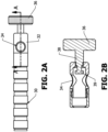
- FIGS. 2A and 2B show a table-mountable flexible arm 30 having an end 32 that includes a hole or aperture 34 therein.
- a securing knob 36 has a shaft 38 with an end 39 that is in communication with the aperture 34such that tightening of the securing knob causes the end 39 to engage shaft 12 of the sheath holder 10 such that the correct orientation/depth and positioning of the scope sheath (and thereby the scope) can be securely maintained.
- a table mountable flexible or rigid arm system as described herein is common to a vast array of surgical procedures. These table mountable systems are anchored to a bar or rail that is mounted on the side of the operating table, commonly used for these types of systems.
- the stabilization system for cystoscopy as disclosed herein comprices a dedicated flexible or rigid arm that connects directly to the bar or rail on the operating table, independent of other table mounted stabilization systems.
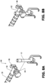
- FIGS. 3A and 3B show an example of how the shaft 12 engages the aperture 34 of the table-mountable flexible arm 30 and is secured in place as described above with reference to FIG. 2 .
- FIGS. 4A-4C there is shown a cystoscope sheath 40 having inflow and outflow ports 42 and an upper surface 44.
- FIGS. 5A and 5B show enlarged views of how the sheath holder 10 engages and secures to the sheath 40.
- the sheath 40 is positioned between the two downwardly extending legs 24A and 24Bsuch that the plunger 16is pushed upward against its spring bias.
- the foot 18 with beveled or curved surface 19 engages the upper surface 44 of the sheath.
- the hooks 26A and 26B hook underneath the inflow and outflow ports 42 as shown.
- the spring biased plunger 16 places a downward force on the sheath 40, pressing the same against the stationary hooks 26A and 26B, and thereby operates to completely stabilize the sheath 40.
- the position of the sheath 40 is now completely adjustable and capable of being secured in any desired position through the sheath holder, as connected to the table-mountable flexible arm 30 through shaft 12 and securing knob 36. This now allows for the introduction of the cystoscope (not shown) into the sheath 40and completely eliminates the need for any personnel to hold or otherwise manually maintain the position of the scope during a surgical procedure.
- FIGS. 6A and 6B show a quick grip attachment system 60 positioned at the end of the table-mountable flexible arm 30.
- the quick grip attachment system 60 includes a channel or slot 62 configured to receive the shaft 12, and a locking handle 64 that, when closed ( FIG. 6B ) compressed against and secure the shaft 12 immovably in the channel 62.
- FIGS. 7A and 7B show an anvil attachment style connection mechanism 70 for connecting the sheath holder 10 to the table-mountable flexible arm 30 via shaft 12.
- the connection mechanism includes an opening 72 to receive the shaft 12, and a sliding collar 74 that locks into place with a rotating collar or knob 76.
- the rotating collar or knob 76 is rotated and translates (via threads not shown) to push and tighten down the sliding collar 74 against the shaft 12.
- a V-shaped feature is included on the rotating collar 74.
- FIGS. 8A and 8B show another anvil attachment style connection mechanism 80 for connecting the sheath holder 10 to the table-mountable flexible arm 30 via shaft 12.
- This connection mechanism includes a base 82 positioned at the end of the table mountable flexible arm and which includes a receiving channel 84 positioned transverse thereto.
- a locking knob 86 is internally threaded such that when the shaft 12 is positioned in the receiving channel 84, it can be locked into place using the knob 86 operating like a screw clamp onto the shaft while contained in the channel 84.
- the shaft 12 includes a notch or groove (e.g., V-shaped) configured to be engaged by the end of the threaded member controlled by knob 86, which has a complementary shape to the notch or groove.
- FIGS. 9A and 9B show another connection mechanism 90 that is a quick connect connection mechanism.
- a quick connect collar 92 is positioned on the end of the table-mountable flexible arm 30 and has a receiving aperture 93.
- a connector 94 that is geometrically sized and shaped to fit into receiving aperture 93 is positioned off the back of the sheath holder 10 such that insertion of the connector 94 into the aperture 93 (and with actuation of the collar 92) locks and secures the sheath holder 10 into the end of the flexible arm.
- FIGS. 10A and 10B show an alternative embodiment of the sheath holder 10 according to yet another embodiment.
- the table-mountable flexible or rigid arm engaging portion and the sheath engaging portion 120 are one in the same and is configured to be fastened directly to an end 32 of the table-mountable flexible arm 30 with screws 122, and includes legs 124A and 124B, with hooks 126A and 126B respectively.
- the plunger assembly includes a shaft 116 with a spring 117 positioned around the same. At the bottom of the plunger shaft 116 is the foot 118 with the beveled or curved surface 119.
- a hole 36 is provided at the top of the flexible arm to allow the shaft 16 to pass therethrough when pushed upward against the downward spring bias.
- This embodiment is an example of a dedicated tip style for a flexible or rigid arm.
Landscapes
- Health & Medical Sciences (AREA)
- Life Sciences & Earth Sciences (AREA)
- Surgery (AREA)
- General Health & Medical Sciences (AREA)
- Public Health (AREA)
- Veterinary Medicine (AREA)
- Pathology (AREA)
- Nuclear Medicine, Radiotherapy & Molecular Imaging (AREA)
- Animal Behavior & Ethology (AREA)
- Engineering & Computer Science (AREA)
- Biomedical Technology (AREA)
- Heart & Thoracic Surgery (AREA)
- Medical Informatics (AREA)
- Molecular Biology (AREA)
- Biophysics (AREA)
- Physics & Mathematics (AREA)
- Radiology & Medical Imaging (AREA)
- Optics & Photonics (AREA)
- Oral & Maxillofacial Surgery (AREA)
- Surgical Instruments (AREA)
- Endoscopes (AREA)
Claims (4)
- Ein Stabilisierungssystem (10) für eine Zielfernrohrhülle (40) mit:einen Eingriffsabschnitt (20) für die Zielfernrohrhülle undeinen Schaft (12), der so konzipiert ist, dass er das Stabilisierungssystem sicher an einem auf einem Tisch montierten flexiblen oder starren Arm (30) befestigt, dadurch gekennzeichnet, dassder Eingriffsabschnitt (20) der Zielfernrohrhülle umfasst eine umgekehrt U-förmige Vorrichtung mit einem oberen Abschnitt, der mit dem Schaft (12) verbunden ist, und zwei nach unten verlaufenden Schenkeln (24A) und (24B), die jeweils einen Haken (26A) und (26B) aufweisen, der an einer Unterseite davon positioniert ist und so konfiguriert ist,dass er eine Zielfernrohrhülle von einer Unterseite der Zuflussöffnung bzw. der Abflussöffnung (42) der Zielfernrohrhülle (40) aus eingreift; und dass der Schaft (12) eine Kolbenanordnung (16), (17), (18) umfasst,die sich nach unten vom oberen Abschnitt erstreckt und zwischen den beiden nach unten verlaufenden Schenkeln (24A) und (24B) platziert ist und so konfiguriert ist, dass sie eine obere Oberfläche (44) der Zielfernrohrhülle (40) eingreift, um die Zielfernrohrhülle vor jeglicher Bewegung zu sichern, sobald sie im Eingriffsabschnitt (20) der Zielfernrohrhülle (40) positioniert ist.
- Das Stabilisierungssystem (10) gemäß Anspruch 1, wobei der Schaft (12) einen oder mehrere Verbindungspunkte (22) umfasst, die dazu konfiguriert sind, den Schaft (12) an dem Eingriffsabschnitt (20) der Zielfernrohrhülle (40) zu befestigen.
- Stabilisierungssystem (10) nach Anspruch 2, wobei der Schaft (12) hohl ist und der Kolbenmechanismus (16), (18), (19) federvorgespannt ist, so dass der hohle Schaft (12) den federvorgespannten Kolbenmechanismus (18), (19) aufnimmt, der als Teil des Eingriffsabschnitts (20) der Zielfernrohrhülle (40) ausgebildet ist, der mit der oberen Oberfläche (44) der Zielfernrohrhülle (40) in Eingriff steht.
- Das Stabilisierungssystem (10) gemäß einem der vorhergehenden Ansprüche, wobei der Schaft (12) ferner so konfiguriert ist, dass er lösbar und sicher von dem am Tisch montierten flexiblen oder starren Arm (30) aufgenommen werden kann, der über einem Patienten positioniert ist.
Applications Claiming Priority (1)
| Application Number | Priority Date | Filing Date | Title |
|---|---|---|---|
| US17/154,530 US12042125B2 (en) | 2021-01-21 | 2021-01-21 | Endoscopic sheath holding tip and stabilization system |
Publications (3)
| Publication Number | Publication Date |
|---|---|
| EP4032496A1 EP4032496A1 (de) | 2022-07-27 |
| EP4032496B1 true EP4032496B1 (de) | 2025-01-08 |
| EP4032496C0 EP4032496C0 (de) | 2025-01-08 |
Family
ID=79730345
Family Applications (1)
| Application Number | Title | Priority Date | Filing Date |
|---|---|---|---|
| EP22152150.3A Active EP4032496B1 (de) | 2021-01-21 | 2022-01-19 | Endoskopische hülle mit spitze und stabilisierungssystem |
Country Status (2)
| Country | Link |
|---|---|
| US (1) | US12042125B2 (de) |
| EP (1) | EP4032496B1 (de) |
Families Citing this family (2)
| Publication number | Priority date | Publication date | Assignee | Title |
|---|---|---|---|---|
| WO2020240270A1 (en) * | 2019-05-31 | 2020-12-03 | Mubarak Muhamed Khan | An apparatus for holding an endoscope |
| USD985771S1 (en) * | 2021-04-27 | 2023-05-09 | Flexbar Machine Corp. | Suture grasper tip |
Family Cites Families (3)
| Publication number | Priority date | Publication date | Assignee | Title |
|---|---|---|---|---|
| US4867404A (en) | 1988-05-16 | 1989-09-19 | The United States Of America As Represented By The Department Of Health And Human Services | Flexible holder for a cystoscope or the like |
| US5224680A (en) | 1991-08-22 | 1993-07-06 | Automated Medical Products Corp. | Surgical instrument holder |
| US20070185376A1 (en) * | 2002-03-11 | 2007-08-09 | Wilson Roger F | System and method for positioning a laparoscopic device |
-
2021
- 2021-01-21 US US17/154,530 patent/US12042125B2/en active Active
-
2022
- 2022-01-19 EP EP22152150.3A patent/EP4032496B1/de active Active
Also Published As
| Publication number | Publication date |
|---|---|
| US12042125B2 (en) | 2024-07-23 |
| US20220225863A1 (en) | 2022-07-21 |
| EP4032496A1 (de) | 2022-07-27 |
| EP4032496C0 (de) | 2025-01-08 |
Similar Documents
| Publication | Publication Date | Title |
|---|---|---|
| US5993385A (en) | Self-aligning side-loading surgical retractor | |
| US20220125492A1 (en) | Implant positioning devices and methods | |
| US8287537B2 (en) | Head fixation device | |
| US20060200005A1 (en) | Low profile, handle-in-between surgical scissors clamp | |
| AU738559B2 (en) | Surgical retraction apparatus | |
| US20030069479A1 (en) | Gooseneck surgical retractor positioner and method of its use | |
| US7749163B2 (en) | Universal scissors joint apparatus | |
| US12490993B2 (en) | Alignment device for a tibial resection guide | |
| US3221743A (en) | System and apparatus for positioning and securing surgical implements | |
| US6056689A (en) | Device and method for localized heart motion dampening at a cardiac surgical site | |
| EP4032496B1 (de) | Endoskopische hülle mit spitze und stabilisierungssystem | |
| US20030149341A1 (en) | Retractor and/or distractor for anterior cervical fusion | |
| US20080249372A1 (en) | Retractor | |
| US10478364B2 (en) | Limb positioning system | |
| CN110811746A (zh) | 旋转旋钮组件和包括该旋转旋钮组件的外科器械 | |
| JP2000507146A (ja) | アクセサリー支持体を備えた手術用開創器 | |
| US10420542B2 (en) | Surgical rib retractor | |
| AU3910099A (en) | Surgical retraction apparatus | |
| US20160051241A1 (en) | Telescoping retractor holder | |
| US10603025B2 (en) | Surgical rib retractor | |
| US11730560B2 (en) | Fast-action clamping device with locking mechanism, and surgical device | |
| US11103126B2 (en) | Surgical equipment holder | |
| CN219480220U (zh) | 一种痔疮手术用结扎钳 | |
| US7887481B2 (en) | Mountable top-loading surgical retractor | |
| WO2007068128A1 (en) | A pair of tongs apt for soft tissue spreading |
Legal Events
| Date | Code | Title | Description |
|---|---|---|---|
| PUAI | Public reference made under article 153(3) epc to a published international application that has entered the european phase |
Free format text: ORIGINAL CODE: 0009012 |
|
| STAA | Information on the status of an ep patent application or granted ep patent |
Free format text: STATUS: REQUEST FOR EXAMINATION WAS MADE |
|
| 17P | Request for examination filed |
Effective date: 20220215 |
|
| AK | Designated contracting states |
Kind code of ref document: A1 Designated state(s): AL AT BE BG CH CY CZ DE DK EE ES FI FR GB GR HR HU IE IS IT LI LT LU LV MC MK MT NL NO PL PT RO RS SE SI SK SM TR |
|
| STAA | Information on the status of an ep patent application or granted ep patent |
Free format text: STATUS: EXAMINATION IS IN PROGRESS |
|
| 17Q | First examination report despatched |
Effective date: 20240510 |
|
| REG | Reference to a national code |
Ref country code: DE Ref legal event code: R079 Free format text: PREVIOUS MAIN CLASS: A61B0090500000 Ipc: A61B0001000000 Ref country code: DE Ref legal event code: R079 Ref document number: 602022009444 Country of ref document: DE Free format text: PREVIOUS MAIN CLASS: A61B0090500000 Ipc: A61B0001000000 |
|
| GRAP | Despatch of communication of intention to grant a patent |
Free format text: ORIGINAL CODE: EPIDOSNIGR1 |
|
| STAA | Information on the status of an ep patent application or granted ep patent |
Free format text: STATUS: GRANT OF PATENT IS INTENDED |
|
| RIC1 | Information provided on ipc code assigned before grant |
Ipc: A61B 90/50 20160101ALI20240906BHEP Ipc: A61B 90/57 20160101ALI20240906BHEP Ipc: A61B 1/00 20060101AFI20240906BHEP |
|
| INTG | Intention to grant announced |
Effective date: 20240930 |
|
| GRAS | Grant fee paid |
Free format text: ORIGINAL CODE: EPIDOSNIGR3 |
|
| GRAA | (expected) grant |
Free format text: ORIGINAL CODE: 0009210 |
|
| STAA | Information on the status of an ep patent application or granted ep patent |
Free format text: STATUS: THE PATENT HAS BEEN GRANTED |
|
| AK | Designated contracting states |
Kind code of ref document: B1 Designated state(s): AL AT BE BG CH CY CZ DE DK EE ES FI FR GB GR HR HU IE IS IT LI LT LU LV MC MK MT NL NO PL PT RO RS SE SI SK SM TR |
|
| REG | Reference to a national code |
Ref country code: GB Ref legal event code: FG4D |
|
| REG | Reference to a national code |
Ref country code: CH Ref legal event code: EP |
|
| REG | Reference to a national code |
Ref country code: DE Ref legal event code: R096 Ref document number: 602022009444 Country of ref document: DE |
|
| REG | Reference to a national code |
Ref country code: IE Ref legal event code: FG4D |
|
| U01 | Request for unitary effect filed |
Effective date: 20250206 |
|
| U07 | Unitary effect registered |
Designated state(s): AT BE BG DE DK EE FI FR IT LT LU LV MT NL PT RO SE SI Effective date: 20250212 |
|
| U1N | Appointed representative for the unitary patent procedure changed after the registration of the unitary effect |
Representative=s name: METIDA; LT |
|
| U20 | Renewal fee for the european patent with unitary effect paid |
Year of fee payment: 4 Effective date: 20250428 |
|
| PG25 | Lapsed in a contracting state [announced via postgrant information from national office to epo] |
Ref country code: RS Free format text: LAPSE BECAUSE OF FAILURE TO SUBMIT A TRANSLATION OF THE DESCRIPTION OR TO PAY THE FEE WITHIN THE PRESCRIBED TIME-LIMIT Effective date: 20250408 |
|
| PG25 | Lapsed in a contracting state [announced via postgrant information from national office to epo] |
Ref country code: PL Free format text: LAPSE BECAUSE OF FAILURE TO SUBMIT A TRANSLATION OF THE DESCRIPTION OR TO PAY THE FEE WITHIN THE PRESCRIBED TIME-LIMIT Effective date: 20250108 |
|
| PG25 | Lapsed in a contracting state [announced via postgrant information from national office to epo] |
Ref country code: ES Free format text: LAPSE BECAUSE OF FAILURE TO SUBMIT A TRANSLATION OF THE DESCRIPTION OR TO PAY THE FEE WITHIN THE PRESCRIBED TIME-LIMIT Effective date: 20250108 |
|
| PG25 | Lapsed in a contracting state [announced via postgrant information from national office to epo] |
Ref country code: NO Free format text: LAPSE BECAUSE OF FAILURE TO SUBMIT A TRANSLATION OF THE DESCRIPTION OR TO PAY THE FEE WITHIN THE PRESCRIBED TIME-LIMIT Effective date: 20250408 Ref country code: IS Free format text: LAPSE BECAUSE OF FAILURE TO SUBMIT A TRANSLATION OF THE DESCRIPTION OR TO PAY THE FEE WITHIN THE PRESCRIBED TIME-LIMIT Effective date: 20250508 |
|
| PG25 | Lapsed in a contracting state [announced via postgrant information from national office to epo] |
Ref country code: HR Free format text: LAPSE BECAUSE OF FAILURE TO SUBMIT A TRANSLATION OF THE DESCRIPTION OR TO PAY THE FEE WITHIN THE PRESCRIBED TIME-LIMIT Effective date: 20250108 |
|
| PG25 | Lapsed in a contracting state [announced via postgrant information from national office to epo] |
Ref country code: GR Free format text: LAPSE BECAUSE OF FAILURE TO SUBMIT A TRANSLATION OF THE DESCRIPTION OR TO PAY THE FEE WITHIN THE PRESCRIBED TIME-LIMIT Effective date: 20250409 |
|
| REG | Reference to a national code |
Ref country code: CH Ref legal event code: PL |
|
| PG25 | Lapsed in a contracting state [announced via postgrant information from national office to epo] |
Ref country code: SM Free format text: LAPSE BECAUSE OF FAILURE TO SUBMIT A TRANSLATION OF THE DESCRIPTION OR TO PAY THE FEE WITHIN THE PRESCRIBED TIME-LIMIT Effective date: 20250108 |
|
| PG25 | Lapsed in a contracting state [announced via postgrant information from national office to epo] |
Ref country code: MC Free format text: LAPSE BECAUSE OF FAILURE TO SUBMIT A TRANSLATION OF THE DESCRIPTION OR TO PAY THE FEE WITHIN THE PRESCRIBED TIME-LIMIT Effective date: 20250108 |
|
| PG25 | Lapsed in a contracting state [announced via postgrant information from national office to epo] |
Ref country code: CH Free format text: LAPSE BECAUSE OF NON-PAYMENT OF DUE FEES Effective date: 20250131 |
|
| PG25 | Lapsed in a contracting state [announced via postgrant information from national office to epo] |
Ref country code: CZ Free format text: LAPSE BECAUSE OF FAILURE TO SUBMIT A TRANSLATION OF THE DESCRIPTION OR TO PAY THE FEE WITHIN THE PRESCRIBED TIME-LIMIT Effective date: 20250108 |
|
| PG25 | Lapsed in a contracting state [announced via postgrant information from national office to epo] |
Ref country code: SK Free format text: LAPSE BECAUSE OF FAILURE TO SUBMIT A TRANSLATION OF THE DESCRIPTION OR TO PAY THE FEE WITHIN THE PRESCRIBED TIME-LIMIT Effective date: 20250108 |
|
| PLBE | No opposition filed within time limit |
Free format text: ORIGINAL CODE: 0009261 |
|
| STAA | Information on the status of an ep patent application or granted ep patent |
Free format text: STATUS: NO OPPOSITION FILED WITHIN TIME LIMIT |
|
| 26N | No opposition filed |
Effective date: 20251009 |
|
| PG25 | Lapsed in a contracting state [announced via postgrant information from national office to epo] |
Ref country code: IE Free format text: LAPSE BECAUSE OF NON-PAYMENT OF DUE FEES Effective date: 20250119 |
|
| U20 | Renewal fee for the european patent with unitary effect paid |
Year of fee payment: 5 Effective date: 20260127 |