EP4032455A1 - Cleaner - Google Patents
Cleaner Download PDFInfo
- Publication number
- EP4032455A1 EP4032455A1 EP20865017.6A EP20865017A EP4032455A1 EP 4032455 A1 EP4032455 A1 EP 4032455A1 EP 20865017 A EP20865017 A EP 20865017A EP 4032455 A1 EP4032455 A1 EP 4032455A1
- Authority
- EP
- European Patent Office
- Prior art keywords
- rotating plate
- cleaner
- support wheel
- mop
- center
- Prior art date
- Legal status (The legal status is an assumption and is not a legal conclusion. Google has not performed a legal analysis and makes no representation as to the accuracy of the status listed.)
- Granted
Links
Images



Classifications
-
- A—HUMAN NECESSITIES
- A47—FURNITURE; DOMESTIC ARTICLES OR APPLIANCES; COFFEE MILLS; SPICE MILLS; SUCTION CLEANERS IN GENERAL
- A47L—DOMESTIC WASHING OR CLEANING; SUCTION CLEANERS IN GENERAL
- A47L11/00—Machines for cleaning floors, carpets, furniture, walls, or wall coverings
- A47L11/40—Parts or details of machines not provided for in groups A47L11/02 - A47L11/38, or not restricted to one of these groups, e.g. handles, arrangements of switches, skirts, buffers, levers
- A47L11/4063—Driving means; Transmission means therefor
-
- A—HUMAN NECESSITIES
- A47—FURNITURE; DOMESTIC ARTICLES OR APPLIANCES; COFFEE MILLS; SPICE MILLS; SUCTION CLEANERS IN GENERAL
- A47L—DOMESTIC WASHING OR CLEANING; SUCTION CLEANERS IN GENERAL
- A47L11/00—Machines for cleaning floors, carpets, furniture, walls, or wall coverings
- A47L11/28—Floor-scrubbing machines, motor-driven
- A47L11/282—Floor-scrubbing machines, motor-driven having rotary tools
-
- A—HUMAN NECESSITIES
- A47—FURNITURE; DOMESTIC ARTICLES OR APPLIANCES; COFFEE MILLS; SPICE MILLS; SUCTION CLEANERS IN GENERAL
- A47L—DOMESTIC WASHING OR CLEANING; SUCTION CLEANERS IN GENERAL
- A47L11/00—Machines for cleaning floors, carpets, furniture, walls, or wall coverings
- A47L11/40—Parts or details of machines not provided for in groups A47L11/02 - A47L11/38, or not restricted to one of these groups, e.g. handles, arrangements of switches, skirts, buffers, levers
- A47L11/4002—Installations of electric equipment
- A47L11/4005—Arrangements of batteries or cells; Electric power supply arrangements
-
- A—HUMAN NECESSITIES
- A47—FURNITURE; DOMESTIC ARTICLES OR APPLIANCES; COFFEE MILLS; SPICE MILLS; SUCTION CLEANERS IN GENERAL
- A47L—DOMESTIC WASHING OR CLEANING; SUCTION CLEANERS IN GENERAL
- A47L11/00—Machines for cleaning floors, carpets, furniture, walls, or wall coverings
- A47L11/40—Parts or details of machines not provided for in groups A47L11/02 - A47L11/38, or not restricted to one of these groups, e.g. handles, arrangements of switches, skirts, buffers, levers
- A47L11/4011—Regulation of the cleaning machine by electric means; Control systems and remote control systems therefor
-
- A—HUMAN NECESSITIES
- A47—FURNITURE; DOMESTIC ARTICLES OR APPLIANCES; COFFEE MILLS; SPICE MILLS; SUCTION CLEANERS IN GENERAL
- A47L—DOMESTIC WASHING OR CLEANING; SUCTION CLEANERS IN GENERAL
- A47L11/00—Machines for cleaning floors, carpets, furniture, walls, or wall coverings
- A47L11/40—Parts or details of machines not provided for in groups A47L11/02 - A47L11/38, or not restricted to one of these groups, e.g. handles, arrangements of switches, skirts, buffers, levers
- A47L11/4036—Parts or details of the surface treating tools
- A47L11/4038—Disk shaped surface treating tools
-
- A—HUMAN NECESSITIES
- A47—FURNITURE; DOMESTIC ARTICLES OR APPLIANCES; COFFEE MILLS; SPICE MILLS; SUCTION CLEANERS IN GENERAL
- A47L—DOMESTIC WASHING OR CLEANING; SUCTION CLEANERS IN GENERAL
- A47L11/00—Machines for cleaning floors, carpets, furniture, walls, or wall coverings
- A47L11/40—Parts or details of machines not provided for in groups A47L11/02 - A47L11/38, or not restricted to one of these groups, e.g. handles, arrangements of switches, skirts, buffers, levers
- A47L11/4061—Steering means; Means for avoiding obstacles; Details related to the place where the driver is accommodated
-
- A—HUMAN NECESSITIES
- A47—FURNITURE; DOMESTIC ARTICLES OR APPLIANCES; COFFEE MILLS; SPICE MILLS; SUCTION CLEANERS IN GENERAL
- A47L—DOMESTIC WASHING OR CLEANING; SUCTION CLEANERS IN GENERAL
- A47L11/00—Machines for cleaning floors, carpets, furniture, walls, or wall coverings
- A47L11/40—Parts or details of machines not provided for in groups A47L11/02 - A47L11/38, or not restricted to one of these groups, e.g. handles, arrangements of switches, skirts, buffers, levers
- A47L11/4063—Driving means; Transmission means therefor
- A47L11/4066—Propulsion of the whole machine
-
- A—HUMAN NECESSITIES
- A47—FURNITURE; DOMESTIC ARTICLES OR APPLIANCES; COFFEE MILLS; SPICE MILLS; SUCTION CLEANERS IN GENERAL
- A47L—DOMESTIC WASHING OR CLEANING; SUCTION CLEANERS IN GENERAL
- A47L11/00—Machines for cleaning floors, carpets, furniture, walls, or wall coverings
- A47L11/40—Parts or details of machines not provided for in groups A47L11/02 - A47L11/38, or not restricted to one of these groups, e.g. handles, arrangements of switches, skirts, buffers, levers
- A47L11/4063—Driving means; Transmission means therefor
- A47L11/4069—Driving or transmission means for the cleaning tools
-
- A—HUMAN NECESSITIES
- A47—FURNITURE; DOMESTIC ARTICLES OR APPLIANCES; COFFEE MILLS; SPICE MILLS; SUCTION CLEANERS IN GENERAL
- A47L—DOMESTIC WASHING OR CLEANING; SUCTION CLEANERS IN GENERAL
- A47L11/00—Machines for cleaning floors, carpets, furniture, walls, or wall coverings
- A47L11/40—Parts or details of machines not provided for in groups A47L11/02 - A47L11/38, or not restricted to one of these groups, e.g. handles, arrangements of switches, skirts, buffers, levers
- A47L11/4072—Arrangement of castors or wheels
-
- A—HUMAN NECESSITIES
- A47—FURNITURE; DOMESTIC ARTICLES OR APPLIANCES; COFFEE MILLS; SPICE MILLS; SUCTION CLEANERS IN GENERAL
- A47L—DOMESTIC WASHING OR CLEANING; SUCTION CLEANERS IN GENERAL
- A47L11/00—Machines for cleaning floors, carpets, furniture, walls, or wall coverings
- A47L11/40—Parts or details of machines not provided for in groups A47L11/02 - A47L11/38, or not restricted to one of these groups, e.g. handles, arrangements of switches, skirts, buffers, levers
- A47L11/408—Means for supplying cleaning or surface treating agents
- A47L11/4083—Liquid supply reservoirs; Preparation of the agents, e.g. mixing devices
-
- A—HUMAN NECESSITIES
- A47—FURNITURE; DOMESTIC ARTICLES OR APPLIANCES; COFFEE MILLS; SPICE MILLS; SUCTION CLEANERS IN GENERAL
- A47L—DOMESTIC WASHING OR CLEANING; SUCTION CLEANERS IN GENERAL
- A47L11/00—Machines for cleaning floors, carpets, furniture, walls, or wall coverings
- A47L11/40—Parts or details of machines not provided for in groups A47L11/02 - A47L11/38, or not restricted to one of these groups, e.g. handles, arrangements of switches, skirts, buffers, levers
- A47L11/408—Means for supplying cleaning or surface treating agents
- A47L11/4088—Supply pumps; Spraying devices; Supply conduits
-
- B—PERFORMING OPERATIONS; TRANSPORTING
- B25—HAND TOOLS; PORTABLE POWER-DRIVEN TOOLS; MANIPULATORS
- B25J—MANIPULATORS; CHAMBERS PROVIDED WITH MANIPULATION DEVICES
- B25J11/00—Manipulators not otherwise provided for
- B25J11/008—Manipulators for service tasks
- B25J11/0085—Cleaning
-
- B—PERFORMING OPERATIONS; TRANSPORTING
- B25—HAND TOOLS; PORTABLE POWER-DRIVEN TOOLS; MANIPULATORS
- B25J—MANIPULATORS; CHAMBERS PROVIDED WITH MANIPULATION DEVICES
- B25J19/00—Accessories fitted to manipulators, e.g. for monitoring, for viewing; Safety devices combined with or specially adapted for use in connection with manipulators
- B25J19/0091—Shock absorbers
-
- B—PERFORMING OPERATIONS; TRANSPORTING
- B25—HAND TOOLS; PORTABLE POWER-DRIVEN TOOLS; MANIPULATORS
- B25J—MANIPULATORS; CHAMBERS PROVIDED WITH MANIPULATION DEVICES
- B25J9/00—Program-controlled manipulators
- B25J9/16—Program controls
- B25J9/1656—Program controls characterised by programming, planning systems for manipulators
- B25J9/1664—Program controls characterised by programming, planning systems for manipulators characterised by motion, path, trajectory planning
- B25J9/1666—Avoiding collision or forbidden zones
-
- B—PERFORMING OPERATIONS; TRANSPORTING
- B25—HAND TOOLS; PORTABLE POWER-DRIVEN TOOLS; MANIPULATORS
- B25J—MANIPULATORS; CHAMBERS PROVIDED WITH MANIPULATION DEVICES
- B25J9/00—Program-controlled manipulators
- B25J9/16—Program controls
- B25J9/1674—Program controls characterised by safety, monitoring, diagnostic
- B25J9/1676—Avoiding collision or forbidden zones
-
- A—HUMAN NECESSITIES
- A47—FURNITURE; DOMESTIC ARTICLES OR APPLIANCES; COFFEE MILLS; SPICE MILLS; SUCTION CLEANERS IN GENERAL
- A47L—DOMESTIC WASHING OR CLEANING; SUCTION CLEANERS IN GENERAL
- A47L2201/00—Robotic cleaning machines, i.e. with automatic control of the travelling movement or the cleaning operation
- A47L2201/04—Automatic control of the travelling movement; Automatic obstacle detection
Definitions
- the present disclosure relates to a cleaner, and more specifically, to a cleaner capable of mopping a floor by a pair of mops that rotate while coming into contact with the floor.
- a robot cleaner may include a motor, various sensors, and artificial intelligence (AI) technology to clean an area requiring cleaning while traveling autonomously.
- AI artificial intelligence
- the robot cleaner may be configured to suction dust using a vacuum, to sweep up dust, or to wipe a surface using a mop.
- Korean Patent No. 10-1613446 discloses "a robot cleaner and a method for operating it.”
- the robot cleaner disclosed in related art 1 includes a main body, a driver, a first rotating member and a second rotating member.
- the robot cleaner disclosed in related art 1 includes a first cleaner and a second cleaner made of cloth, a mop, a nonwoven fabric, a brush, or the like.
- the first cleaner is coupled to a first fixing member of the first rotating member
- the second cleaner is coupled to a second fixing member of the second rotating member.
- related art 1 As the first cleaner and the second cleaner are rotated by the rotational motion of the first rotating member and the second rotating member, foreign matter stuck to the floor may be removed through friction with the floor surface, and when a frictional force with the floor surface is generated, the frictional force can be used as power for moving the robot cleaner. That is, related art 1 describes that the robot cleaner can move while cleaning the floor based on the first cleaner and the second cleaner being rotated.
- At least one of the first cleaner or the second cleaner may be separated, respectively, from the first fixing member or the second fixing member.
- the robot cleaner may be inadvertently operated while at least one of the first cleaner or the second cleaner is separated from the robot cleaner. For example, a user may accidentally operate the robot cleaner without recognizing that the first cleaner or the second cleaner is separated from the robot cleaner, or the first cleaner or the second cleaner may unintendedly become separated from the robot cleaner by friction with the floor or due to jamming.
- first fixing member or the second fixing member are rotated while directly rubbing against the floor, the first fixing member or the second fixing member may be damaged or may scratch the floor.
- the robot cleaner disclosed in related art 1 includes a liquid management unit for discharging liquid to the first cleaner and the second cleaner.
- related art 1 fails to consider or recognize an issue relating to consumption of the liquid stored in the liquid management unit.
- the liquid stored in the liquid management unit decreases as a result of use.
- the robot cleaner may become imbalanced as the center of gravity in the entire robot cleaner changes. As a result, the robot cleaner may not move or clean as intended.
- the liquid management unit may be disposed at a center position such that a center of gravity of the liquid management unit corresponds to the center of gravity of the first type of robot cleaner, and the center of gravity of the robot cleaner does not change as liquid is used, but this design may cause many design constraints.
- Korean Patent Registration No. 10-2000068 discloses a cleaner that includes a mop module including a mop portion and a collection module.
- the cleaner disclosed in related art 2 provides various advantages such as effective mopping and travelling, the mop part easily detachable from the cleaner and easier manipulation of the cleaner.
- improvement of the cleaner is required when taking account of the following problems.
- the cleaner disclosed in related art 2 includes a mop portion and a rotating plate.
- the mop portion is detachable from a mop fixing portion of the rotating plate.
- the cleaner may be operated while the mop portion is separated from the cleaner. In this case, the rotating plate or the floor may be damaged, as described in relation to related art 1.
- An aspect of the present disclosure is to provide a cleaner equipped with a pair of mops that rotate in contact with the floor, capable of preventing the cleaner from being damaged or the floor from being damaged even when the cleaner is operated in a separated state in which the mops are separated from the cleaner.
- Another aspect of the present disclosure is to provide a cleaner in which mops come into intensive contact with the floor when the mops are coupled to the cleaner, and parts coupled to the mops are spaced apart from the floor when the mops are separated from the cleaner.
- Still another aspect of the present disclosure is to provide a cleaner equipped with a water container configured to supply liquid (water) to a pair of mops, capable of facilitating stable contact and friction between the mops and the floor when the entire center of gravity of the cleaner changes in accordance with consumption of the liquid, even when the water container is not disposed at the center of gravity of the cleaner.
- a water container configured to supply liquid (water) to a pair of mops, capable of facilitating stable contact and friction between the mops and the floor when the entire center of gravity of the cleaner changes in accordance with consumption of the liquid, even when the water container is not disposed at the center of gravity of the cleaner.
- Still another aspect of the present disclosure is to provide a cleaner capable of facilitating stable mopping even when a motor, a battery, and a water container are respectively disposed at different positions so as to form a relatively flat cleaner.
- Still another aspect of the present disclosure is to provide a cleaner in which a traveling direction of the cleaner can be controlled by a pair of mops rotating in contact with the floor, and that includes an auxiliary means for controlling the traveling direction of the cleaner.
- a cleaner according to an embodiment of the present disclosure includes a body, a first rotating plate, a second rotating plate, a first mop, and a second mop.
- the cleaner according to an embodiment of the present disclosure may be made to move automatically even when no separate external force is applied. That is, the cleaner according to an embodiment of the present disclosure may be made to move like a common 'robot cleaner.'
- the body may form the overall exterior of the cleaner, or be formed as a frame to which other components of the cleaner are coupled.
- first rotating plate and the second rotating plate are rotatably coupled to the body.
- the first rotating plate may be coupled to the lower portion of the body, and the second rotating plate may also be coupled to the lower portion of the body.
- the first mop may be detachably attached to a lower surface of the first rotating plate, and may be coupled to the first rotating plate to rotate with the first rotating plate.
- the second mop may be detachably attached to a lower surface of the second rotating plate, and may be coupled to the second rotating plate to rotate with the second rotating plate.
- the first mop and the second mop come into contact with the floor when the first mop is coupled to the first rotating plate and the second mop is coupled to the second rotating plate, and the first rotating plate and the second rotating plate are spaced apart from the floor when the first mop and the second mop are separated from the first rotating plate and the second rotating plate.
- the cleaner includes a supporting means.
- the cleaner according to an embodiment of the present disclosure may include a support wheel and an auxiliary wheel as the supporting means.
- the cleaner according to an embodiment of the present disclosure may include a first support wheel, a second support wheel, and an auxiliary wheel as the supporting means.
- the support wheel may be coupled to the lower portion of the body.
- the auxiliary wheel may also be coupled to the lower portion of the body.
- the auxiliary wheel may be disposed at the opposite side of the support wheel with respect to a virtual connection line connecting the center of the first rotating plate to the center of the second rotating plate.
- the lowest part of the first rotating plate and the lowest part of the second rotating plate may be positioned higher than a virtual reference line connecting the lowest part of the support wheel to the lowest part of the auxiliary wheel, and the lowest part of the first mop and the lowest part of the second mop may be positioned lower than the reference line.
- the first support wheel may be coupled to the lower portion of the bodv.
- the second support wheel may be spaced apart from the first support wheel and coupled to the body at the same side of the first support wheel with respect to the connection line.
- the first support wheel may be disposed to be closer to the first rotating plate than the second rotating plate, and the second support wheel may be disposed to be closer to the second rotating plate than the first rotating plate.
- the first support wheel may be coupled to the body in front of the first rotating plate, and the second support wheel may be coupled to the body in front of the second rotating plate.
- the auxiliary wheel may be coupled to the body at the other side of the first support wheel with respect to the connection line.
- the auxiliary wheel may be coupled to the body behind the center of the first rotating plate and the center of the second rotating plate.
- the lowest part of the first rotating plate may be positioned above a first virtual reference line connecting the lowest part of the first support wheel to the lowest part of the auxiliary wheel, and the lowest part of the first mop may be positioned below the first reference line.
- the lowest part of the second rotating plate may be positioned above a second virtual reference line connecting the lowest part of the second support wheel to the lowest part of the auxiliary wheel, and the lowest part of the second mop may be positioned below the second reference line.
- the first rotating plate and the second rotating plate may be symmetrical to each other, and the first support wheel and the second support wheel may be symmetrical to each other.
- the first support wheel, the second support wheel, and the auxiliary wheel may respectively be disposed so as not to interrupt movement (traveling) of the cleaner by a frictional force with the floor, and not to cause a load increase when the cleaner moves.
- the width of each of the first support wheel, the second support wheel, and the auxiliary wheel may be formed to be significantly small in comparison to a diameter of the first rotating plate or a diameter of the second rotating plate.
- the width of each of the first support wheel, the second support wheel, and the auxiliary wheel may be formed to be smaller than 1/10 of the diameter of the first rotating plate or the diameter of the second rotating plate.
- the diameter of each of the first rotating plate and the second rotating plate may be formed to be greater than 1/3 of the diameter of the body and smaller than 1/2 of the diameter of the body.
- the diameter of each of the first mop and the second mop may be formed to be greater than 1/3 of the diameter of the body and smaller than 2/3 of the diameter of the body.
- the first support wheel and the second support wheel and the first mop and the second mop may be disposed at such a distance with respect to each other that the cleaner may be stably supported thereby at four points.
- C1 when a horizontal distance between the center of the first support wheel and the center of the second support wheel is C1 and a distance between the center of rotation of the first rotating plate and the center of rotation of the second rotating plate is C2, C1 may be greater than 0.8 ⁇ C2 and smaller than 1.2 ⁇ C2.
- the cleaner according to an embodiment of the present disclosure is configured such that, when coming into contact with the floor, the first support wheel and the second support wheel and the first mop and the second mop assist in forward movement of the cleaner.
- a rotation axis of the first support wheel and a rotation axis of the second support wheel may be formed to be parallel to a virtual connection line connecting the rotation axis of the first rotating plate to the rotation axis of the second rotating plate.
- the auxiliary wheel may be coupled to the body via an auxiliary wheel body that is rotatably coupled to the lower portion of the body, and a rotation axis of the auxiliary wheel and a rotation axis of the auxiliary wheel body may be formed to intersect each other.
- the center of gravity of the cleaner may be located inside a rectangular vertical area formed using the center of the first rotating plate, the center of the second rotating plate, the center of the first support wheel, and the center of the second support wheel as the respective vertices.
- the cleaner according to an embodiment of the present disclosure may be supported at four points by the first mop, the second mop, the first support wheel, and the second support wheel.
- the first rotating plate and the second rotating plate may be inclined with respect to the connection line such that the sides of the first rotating plate and the second rotating plate that are closer to each other are spaced further apart from the floor surface than the sides of the first rotating plate and the second rotating plate that are farther from each other.
- the cleaner according to an embodiment of the present disclosure may further include a water container and a water supply tube.
- the water container is formed as a container so as to store liquid therein, and is coupled to the body.
- the water supply tube is formed as a tube or a pipe, and is connected to the water container so as to supply liquid in the water container to the first mop and the second mop.
- the water container may be disposed above the auxiliary wheel.
- the cleaner according to an embodiment of the present disclosure may further include a first actuator, a second actuator, and a battery.
- the first actuator may be coupled to the body to rotate the first rotating plate.
- the first actuator may have a center of gravity located inside a vertical area associated with the first rotating plate.
- the second actuator may be disposed in the body to rotate the second rotating plate.
- the second actuator may have a center of gravity located inside a vertical area associated with the second rotating plate.
- the battery may be coupled to the body to supply a power source to the first actuator and the second actuator, and may be disposed in a rectangular vertical area formed using the center of the first rotating plate, the center of the second rotating plate, the center of the first support wheel, and the center of the second support wheel as the respective vertices.
- the cleaner according to an embodiment of the present disclosure may further include a controller configured to control the operation of the first actuator and the second actuator based on predetermined information or real-time information.
- the cleaner according to an embodiment of the present disclosure may further include a bumper, a first sensor, and a second sensor.
- the bumper may be coupled along the edge of the body so as to move relative to the body.
- the first sensor may be coupled to the body, and may sense the movement of the bumper relative to the body.
- the controller may be configured to control the operation of the first actuator and the second actuator based on information of the first sensor.
- the second sensor may be coupled to the body, and may sense a relative distance from an obstacle.
- the controller may be configured to control the operation of the first actuator and the second actuator based on information of the second sensor.
- the cleaner includes the support wheel (the first support wheel and the second support wheel) and the auxiliary wheel, in which the lowest parts of the first rotating plate and the second rotating plate are higher than the virtual reference line connecting the lowest part of the support wheel to the lowest part of the auxiliary wheel, and the lowest parts of the first mop and the second mop are lower than the reference line.
- mopping may be performed by the first mop and the second mop when the first mop and the second mop are coupled to the first rotating plate and the second rotating plate, and the first rotating plate and the second rotating plate may be spaced apart from the floor when the first mop and the second mop are separated from the first rotating plate and the second rotating plate.
- the cleaner may prevent the first rotating plate and the second rotating plate from rubbing against the floor even when the operation of the cleaner is performed when the first mop and the second mop are separated from the first rotating plate and the second rotating plate.
- the present disclosure can provide an effect of effectively preventing the cleaner or the floor from being damaged as the support wheel and the auxiliary wheel move while rolling on the floor, even when the cleaner unintendedly moves on the floor.
- the cleaner includes the first actuator disposed above the first rotating plate, the second actuator disposed above the second rotating plate, the battery disposed to lean toward the first support wheel and the second support wheel, and the water container disposed above the auxiliary wheel. Accordingly, upon initial operation of the cleaner, cleaning can be performed while only the first mop and the second mop contact the floor, and as the liquid is exhausted, cleaning can be performed while the first mop and the second mop and the first support wheel and the second support wheel contact the floor.
- the cleaner includes a water container which is not disposed at the center of gravity, and the height of the cleaner can be formed to be relatively low (flat).
- the first support wheel and the second support wheel can assist in forward movement of the cleaner.
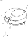
- FIG. 1 is a diagram illustrating a perspective view of a cleaner 1 according to an embodiment of the present disclosure.
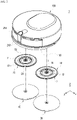
- FIG. 2 is a diagram illustrating the partial configuration separated from the cleaner 1 shown in FIG. 1 .
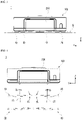
- FIG. 3 is a diagram illustrating a back view of the cleaner 1 shown in FIG. 1 .
- FIG. 4 is a diagram illustrating the partial configuration separated from the cleaner 1 shown in FIG. 3 .
- the cleaner 1 may be a robot cleaner 1.
- the cleaner 1 according to an embodiment of the present disclosure may be placed on a floor surface B and may move along and clean the floor surface B. Accordingly, hereinafter, in order to describe the cleaner 1, a vertical direction may be set based on a state in which the cleaner 1 is placed on the floor.
- the 'lowest part' of a component described in embodiments of the present disclosure may be a part at which each component is located lowest or closest to the floor when the cleaner 1 is placed on the floor.
- the cleaner 1 may include a body 100, a first rotating plate 10, a second rotating plate 20, a first mop 30, and a second mop 40.
- the body 100 may form an overall appearance of the cleaner 1 or may be formed as a frame. Each component constituting the cleaner 1 may be coupled to the body 100, and some components constituting the cleaner 1 may be accommodated in the body 100.
- the body 100 may be divided into a lower body 100a and an upper body 100b, and the components of the cleaner 1 may be provided in a space where the lower body 100a and the upper body 100b are coupled to each other (see FIG. 10 ).
- the body 100 may have a width (or diameter) larger in the horizontal direction (direction parallel to X and Y) than the height in the vertical direction (direction parallel to Z). Such a body 100 may provide an advantageous structure for helping the cleaner 1 to have a stable structure and to avoid obstacles when moving (traveling).
- the body 100 When viewed from above or below, the body 100 may be formed in various forms, such as a circle, an oval, or a rectangle.
- the first rotating plate 10 may be formed to have a predetermined area and may be formed substantially in the form of a flat plate or a flat frame.
- the first rotating plate 10 may generally be positioned to extend substantially horizontally. As such, the first rotating plate 10 has a width (or diameter) in the horizontal direction set to be significantly larger than the height in the vertical direction.
- the first rotating plate 10 coupled to the body 100 may be parallel to the floor surface B, or may be inclined with respect to the floor surface B.
- the first rotating plate 10 may be formed in a circular plate shape, and the bottom surface of the first rotating plate 10 may generally have a circular shape.
- the first rotating plate 10 may be formed in a rotationally symmetrical form as a whole.
- the first rotating plate 10 may include a first central plate 11, a first outer plate 12, and first spokes 13.
- the first central plate 11 may be rotatably coupled to the body 100 while forming the center of the first rotating plate 10.
- the first central plate 11 may be coupled to the lower portion of the body 100, and the upper surface of the first central plate 11 may be coupled to a lower surface of the body 100 while facing the lower surface of the body 100.
- a rotation axis 15 of the first rotating plate 10 may be formed along a direction passing through the center of the first central plate 11.
- the rotation axis 15 of the first rotating plate 10 may be formed along a direction orthogonal to the floor surface B, or may have a predetermined inclination with respect to the direction perpendicular to the floor surface B.
- the first outer plate 12 may be formed to surround the first central plate 11 while being spaced apart from the first central plate 11.
- the first spokes 13 may connect the first central plate 11 and the first outer plate 12, and are provided in plural and are repeatedly formed along the circumferential direction of the first central plate 11.
- the first spokes 13 may be arranged at equal intervals.
- a plurality of holes 14 penetrating vertically between the first spokes 13 may be provided, and a liquid (such as water) discharged from a water supply tube 240 to be described below may be transferred to the first mop 30 through the holes 14.
- the bottom surface of the first rotating plate 10 coupled to the body 100 may form a predetermined incline with respect to the floor surface B.
- the rotation axis 15 of the first rotating plate 10 may have a predetermined incline with respect to a direction perpendicular to the floor surface B.
- an angle ⁇ 1 formed between the bottom surface of the first rotating plate 10 and the floor surface B may be correspond to an angle ⁇ 2 formed between the rotation axis 15 of the first rotating plate 10 and the direction perpendicular to the floor surface B. Accordingly, when the first rotating plate 10 rotates with respect to the body 100, the bottom surface of the first rotating plate 10 may be configured to maintain the same angle with the floor surface B.
- the second rotating plate 20 may be formed to have a predetermined area and may be formed in the form of a flat plate or a flat frame.
- the second rotating plate 20 generally lies horizontally. As such, a width (or diameter) in the horizontal direction may be set to be significantly larger than the height in the vertical direction.
- the second rotating plate 20 coupled to the body 100 may be disposed parallel to the floor surface B, or may be inclined with respect to the floor surface B.
- the second rotating plate 20 may be formed in a substantially circular plate shape, and the bottom surface of the second rotating plate 20 may generally have a circular shape.
- the second rotating plate 20 may be formed in a rotationally symmetrical form as a whole.
- the second rotating plate 20 may include a second central plate 21, a second outer plate 22, and second spokes 23.
- the second central plate 21 may be rotatably coupled to the body 100 while forming the center of the second rotating plate 20.
- the second central plate 21 may be coupled to the lower portion of the body 100, and the upper surface of the second central plate 21 may be coupled to a lower surface of the body 100 while facing the lower surface of the body 100.
- a rotation axis 25 of the second rotating plate 20 may be formed along a direction passing through the center of the second central plate 21.
- the rotation axis 25 of the second rotating plate 20 may be formed along a direction orthogonal to the floor surface B, or may have a predetermined inclination with respect to the direction orthogonal to the floor surface B.
- the second outer plate 22 is formed to surround the second central plate 21 while being spaced apart from the second central plate 21.
- the second spokes 23 connect the second central plate 21 and the second outer plate 22, and are provided in plural and are repeatedly formed along the circumferential direction of the second central plate 21.
- the second spokes 23 may be arranged at substantially equal intervals.
- a plurality of holes 24 penetrating vertically between the second spokes 23 may be provided, and the liquid (such as water) discharged from the water supply tube 240 to be described below may be transferred to the second mop 40 through the holes 24.
- the bottom surface of the second rotating plate 20 coupled to the body 100 may form a predetermined incline with respect to the floor surface B.
- the rotation axis 25 of the second rotating plate 20 may have a predetermined incline with respect to a direction perpendicular to the floor surface B.
- an angle ⁇ 3, which is formed between the bottom surface of the second rotating plate 20 and the floor surface B, may substantially correspond to angle ⁇ 4, which is formed between the rotation axis 25 of the second rotating plate 20 and the direction perpendicular to the floor surface B. Accordingly, when the second rotating plate 20 rotates with respect to the body 100, the bottom surface of the second rotating plate 20 may be configured to maintain a same angle with the floor surface B.
- the second rotating plate 20 may be formed to correspond to the first rotating plate 10, or may be formed to be symmetrical to the first rotating plate 10.
- the first rotating plate 10 may be located on the left side of the cleaner 1, whereas the second rotating plate 20 may be located on the right side of the cleaner 1.
- the first rotating plate 10 and the second rotating plate 20 may be bilaterally symmetrical to each other with respect to a midline of the body 100 extending in a front-to-rear direction.
- the first mop 30 may be formed so that a bottom surface thereof that faces the floor B has a predetermined area, and the first mop 30 has a flat shape.
- the first mop 30 may have a shape in which the width (or diameter) thereof in the horizontal direction is significantly larger than the height in the vertical direction.
- the bottom surface of the first mop 30 may be parallel to the floor surface B, or may be inclined with respect to the floor surface B.
- the bottom surface of the first mop 30 may be generally circular.
- the second mop 30 may be formed in a rotationally symmetrical form as a whole.
- the second mop 30 may be made of various materials that can clean the floor while being in contact with the floor.
- the bottom surface of the first mop 30 may be made of a cloth made of a woven or knitted fabric, a nonwoven fabric, and/or a brush having a predetermined area.
- the first mop 30 may be detachably attached to the bottom surface of the first rotating plate 10, and may be coupled to the first rotating plate 10 to be rotated together with the first rotating plate 10.
- the first mop 30 may be in close contact with the bottom surface of the first outer plate 12, and may be in close contact with the bottom surface of the first central plate 11 and the first outer plate 12.
- the first mop 30 may be detachably attached to the second rotating plate 10 using various devices and methods.
- at least a portion of the first mop 30 may be coupled to the first rotating plate 10 by being hooked to or inserted into the first rotating plate 10.
- a separate device such as a clamp that couples the first mop 30 to the first rotating plate 10
- one side of one pair of fastening devices that can be coupled to and separated from each other may be fixed to the first mop 30, and the other side thereof may be fixed to the first rotating plate 10.
- a pair of magnets that work with each other a pair of strips of Velcro that are coupled to each other, or a pair of buttons (a female button and a male button) that are coupled to each other may be used.
- the first mop 30 and the first rotating plate 10 may be coupled to overlap each other, and the first mop 30 may be coupled to the first rotating plate 10 such that the center of the first mop 30 coincides with the center (e.g., rotational axis 15) of the first rotating plate 10.
- the second mop 40 may be formed so that a bottom surface thereof that faces the floor has a predetermined area, and the second mop 40 has a flat shape.
- the second mop 40 has a shape in which the width (or diameter) in the horizontal direction is significantly larger than the height in the vertical direction.
- the bottom surface of the second mop 40 may be parallel to the floor surface B, or may be inclined with respect to the floor surface B.
- the bottom surface of the second mop 40 may be generally circular.
- the second mop 40 may be formed in a rotationally symmetrical form as a whole.
- the second mop 40 may be made of various materials that can clean the floor while being in contact with the floor.
- the bottom surface of the second mop 40 may be made of a cloth made of a woven or knitted fabric, a nonwoven fabric, and/or a brush having a predetermined area.
- the second mop 40 may be detachably attached to the bottom surface of the second rotating plate 20, and may be coupled to the second rotating plate 20 to be rotated together with the second rotating plate 20.
- the second mop 40 may be in close contact with the bottom surface of the second outer plate 22, and may be in close contact with the bottom surface of the second central plate 21 and the second outer plate 22.
- the second mop 40 may be detachably attached to the second rotating plate 20 using various devices and methods.
- at least a portion of the second mop 40 may be coupled to the second rotating plate 40 by being hooked to or inserted into the second rotating plate 20.
- a separate device such as a clamp, which couples the second mop 30 to the second rotating plate 10, may be provided.
- one side of one pair of fastening devices coupled to and separated from each other may be fixed to the second mop 40 and the other side thereof may be fixed to the second rotating plate 20.
- a pair of magnets that work with each other a pair of strips of Velcro that are coupled to each other, or a pair of buttons (a female button and a male button) that are coupled to each other may be used.
- the second mop 40 and the second rotating plate 20 may be coupled to overlap each other, and the second mop 40 may be coupled to the second rotating plate 20 such that the center of the second mop 40 coincides with the center (e.g., rotational axis 25) of the second rotating plate 20.
- the first rotating plate 10 and the second rotating plate 20 may respectively be inclined with respect to the floor surface B such that the sides of the first rotating plate 10 and the second rotating plate 20 that are closer to each other are spaced further apart from the floor surface B than the sides of the first rotating plate 10 and the second rotating plate 20 that are farther from each other. That is, the first rotating plate 10 and the second rotating plate 20 may be formed such that the sides thereof that are farther from the center of the cleaner 1 are located closer to the floor than the sides thereof that are closer to the center of the cleaner 1 (see FIGS. 3 and 4 ).
- the rotation axis 15 of the first rotating plate 10 may be formed to be perpendicular to the bottom surface of the first rotating plate 10
- the rotation axis 25 of the second rotating plate 20 may be formed to be perpendicular to the bottom surface of the second rotating plate 20.
- the sides of the first mop 30 and the second mop 40 that are farther from each other may be in relatively stronger contact with the floor.
- the cleaner 1 may move straight, forward or backward.
- the cleaner 1 may move forward when the first rotating plate 10 rotates counterclockwise and the second rotating plate 20 rotates clockwise.
- the cleaner 1 may change direction.
- the cleaner 1 can move while changing direction, and can move in a curved direction.
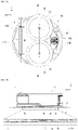
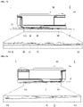
- FIG. 5A is a diagram illustrating a bottom view of the cleaner 1 according to another embodiment of the present disclosure
- FIG. 5B is a diagram illustrating a side view of the cleaner 1 shown in FIG. 5A .
- the cleaner 1 may include at least one support wheel 110 and an auxiliary wheel 140.
- the support wheel 110 may be coupled to the lower portion of the body 100 while being spaced apart from the first rotating plate 10 and the second rotating plate 20.
- the support wheel 110 may be formed as a common wheel.
- the support wheel 110 has a rotation axis formed to be parallel to the floor surface B.
- the support wheel 110 may move while rolling in contact with the floor. As a result, the cleaner 1 may move along the floor surface B.
- the support wheel 110 may contact the floor together with the first mop 30 and the second mop 40.
- a width W1 of the support wheel 110 in the direction of the rotation axis may be formed to be relatively wide. More specifically, when the support wheel 110 is placed on the floor surface B (when the rotation axis of the support wheel 110 is parallel to the floor surface B), one support wheel 110 may be formed have a width W1 capable of supporting a part of the load of the cleaner 1 such that the cleaner 1 remains upright without falling sideways.
- the support wheel 110 may be formed to have a shape such as a roller.
- the auxiliary wheel 140 may be coupled to the lower portion of the body 100 while being spaced apart from the first rotating plate 10 and the second rotating plate 20.
- connection line L1 is a virtual line connecting the center of the first rotating plate 10 to the center of the second rotating plate 20 along a horizontal direction (e.g., in a direction parallel to the floor surface B), and the auxiliary wheel 140 and the support wheel 110 may be positioned at opposite sides of the bottom surface of the body 100 with respect to the connection line L1.
- the auxiliary wheel 140 may be formed as a common wheel.
- the auxiliary wheel 140 may have a rotation axis 145 formed parallel to the floor surface B.
- the auxiliary wheel 140 may move while rolling in contact with the floor. As a result, the cleaner 1 may move along the floor surface B.
- auxiliary wheel 140 may not come into contact with the floor surface B when the first mop 30 and the second mop 40 come into contact with the floor.
- the cleaner 1 may be formed to move straight along the floor surface B.
- the cleaner 1 may move straight in the forward direction (toward the X direction), or straight in the backward direction, such as to avoid an obstacle or a drop.
- the lowest parts of the first rotating plate 10 and the second rotating plate 20 may be formed to be higher than a virtual reference line L2 connecting the lowest part of the support wheel 110 to the lowest part of the auxiliary wheel 140, and the lowest parts of the first mop 30 and the second mop 40 may be formed to be lower than the reference line L2.
- the support wheel 110 and the auxiliary wheel 140 do not interfere with the contact of the first mop 30 and the second mop 40 with the floor when the first mop 30 is coupled to the first rotating plate 10 and the second mop 40 is coupled to the second rotating plate 20.
- the first mop 30 and the second mop 40 may come into contact with the floor, and mopping and cleaning can be performed by rotation of the first mop 30 and the second mop 40.
- the support wheel 110 and the auxiliary wheel 140 may be spaced apart from the floor when the first mop 30 and the second mop 40 contact the floor.
- the auxiliary wheel 140 may be spaced apart from the floor while the support wheel 110, the first mop 30, and the second mop 40 come into contact with the floor.
- the height from the floor surface B to the lowest part of the support wheel 110 is formed to be lower than the height from the floor surface B to the lowest part of the auxiliary wheel 140.
- the support wheel 110 and the auxiliary wheel 140 may contact the floor, and lower surfaces of the first rotating plate 10 and the second rotating plate 20 may be spaced apart from the floor.
- the configuration of cleaner 1 helps to prevent the first rotating plate 10 and the second rotating plate 20 from coming into contact with the floor and rubbing against the floor. As a result, damage to the first rotating plate 10 and the second rotating plate 20 may be avoided, and damage to the floor may be avoided.
- the present disclosure may provide an effect of preventing the floor from being scratched, and effectively avoiding damage being caused to the cleaner 1 or the floor.
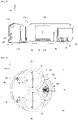
- FIG. 6 is a diagram illustrating a bottom view of the cleaner 1 according to still another embodiment of the present disclosure.
- FIGS. 7A and 7B are diagrams illustrating a side view of the cleaner 1 shown in FIG. 6 .
- FIGS. 8A and 8B are diagrams illustrating a side view of the cleaner 1 while excluding a partial configuration of the cleaner shown in FIG. 6 .
- the cleaner 1 may include a first support wheel 120, a second support wheel 130, and an auxiliary wheel 140.
- the auxiliary wheel 140 may be formed as described above.
- the first support wheel 120 and the second support wheel 130 are spaced apart from each other, and may be formed as common wheels.
- the first support wheel 120 and the second support wheel 130 may move while rolling in contact with the floor.
- the cleaner 1 may move along the floor surface B.
- the first support wheel 120 may be coupled to the bottom surface of the body 100 at a position spaced apart from the first rotating plate 10 and the second rotating plate 20, and the second support wheel 130 may also be coupled to the bottom surface of the body 100 at a position spaced apart from the first rotating plate 10 and the second rotating plate 20.
- the second support wheel 130 is disposed at the same side as the first support wheel 120 (e.g., at a front of the body 100) with respect to the aforementioned connection line L1.
- the auxiliary wheel 140 may be disposed at the opposite side to the first support wheel 120 with respect to the connection line L1. That is, the first support wheel 120 and the second support wheel 130 may be disposed in front of the connection line L1, and the auxiliary wheel 140 may be disposed behind the connection line L1.
- a space between the first support wheel 120 and the second support wheel 130 may be formed to be relatively wide. More specifically, when the first support wheel 120 and the second support wheel 130 are placed on the floor surface B (when the rotation axis 125 of the first support wheel 120 and the rotation axis 135 of the second support wheel 130 are substantially parallel to the floor surface B), the first support wheel 120 and the second support wheel 130 may be spaced apart and support at least a part of the load of the cleaner 1 such that the cleaner 1 remains upright without falling sideways.
- the first support wheel 120 may be disposed in front of the first rotating plate 10
- the second support wheel 130 may be disposed in front of the second rotating plate 20.
- the first rotating plate 10 and the second rotating plate 20 may be (bilaterally) symmetrical to each other, and the first support wheel 120 and the second support wheel 130 may be (bilaterally) symmetrical to each other with respect to the midline of the body 100 that extends in the front-to-rear direction.
- the lowest part of the first rotating plate 10 may be formed to be higher than a first virtual reference line L3 connecting the lowest part of the first support wheel 120 to the lowest part of the auxiliary wheel 140, and the lowest part of the first mop 30 may be formed to be lower than the first reference line L3 (see FIG. 8A ).
- the lowest part of the second rotating plate 20 may be formed to be higher than a second virtual reference line L4 connecting the lowest part of the second support wheel 130 to the lowest part of the auxiliary wheel 140, and the lowest part of the second mop 40 may be formed to be lower than the second reference line L4 (see FIG. 8B ).
- the first support wheel 120, the second support wheel 130, and the auxiliary wheel 140 do not interfere with the contact of the first mop 30 and the second mop 40 with the floor when the first mop 30 is coupled to the first rotating plate 10 and the second mop 40 is coupled to the second rotating plate 20.
- the first mop 30 and the second mop 40 may come into contact with the floor, and mopping and cleaning can be performed by rotation of the first mop 30 and the second mop 40.
- the first support wheel 120, the second support wheel 130 and the auxiliary wheel 140 may be spaced apart from the floor.
- the auxiliary wheel 140 may be spaced apart from the floor while the first support wheel 120 and the second support wheel 130 come into contact with the floor while the first mop 30 and the second mop 40 contact the floor.
- the heights from the floor surface B to the lowest part of the first support wheel 120 and from the floor surface B to the lowest part of the second support wheel 130 may be lower than the height from the floor surface B to the lowest part of the auxiliary wheel 140.
- first support wheel 120, the second support wheel 130 and the auxiliary wheel 140 may contact the floor, and the first rotating plate 10 and the second rotating plate 20 may be spaced apart from the floor (see FIGS. 8A and 8B ).
- the cleaner 1 is capable of preventing the first rotating plate 10 and the second rotating plate 20 from coming into contact with the floor and rubbing against the floor. As a result, damage to the first rotating plate 10 and the second rotating plate 20 may be avoided, and damage to the floor may be avoided.
- the first support wheel 120, the second support wheel 130 and the auxiliary wheel 140 can easily roll on the floor, thereby preventing the floor from being scratched, and effectively avoiding damage to the cleaner 1 or the floor.
- FIG. 9 is a diagram illustrating a bottom view of the cleaner 1 according to still another embodiment of the present disclosure
- FIG. 10 is a diagram illustrating an exploded perspective view of the cleaner 1 shown in FIG. 9 .
- the cleaner 1 may include a first actuator 160, a second actuator 170, a battery 220, a water container 230, and a water supply tube 240.
- the first actuator 160 may be coupled to the body 100 to rotate the first rotating plate 10.
- the first actuator 160 may include a first case 161, a first motor 162, and one or more first gears 163.
- the first case 161 may support the components constituting the first actuator 160, and may be fixedly coupled to the body 100.
- the first motor 162 may be formed as an electric motor.
- a plurality of first gears 163 may be formed to rotate while being engaged with each other.
- the first gears 163 may connect the first motor 162 to the first rotating plate 10, and may transmit rotational power of the first motor 162 to the first rotating plate 10.
- the first rotating plate 10 may rotate upon rotation of the rotation axis of the first motor 162.
- the second actuator 170 may be coupled to the body 100 to rotate the second rotating plate 20.
- the second actuator 170 may include a second case 171, a second motor 172, and one or more second gears 173.
- the second case 171 may support the components constituting the second actuator 170, and may be fixedly coupled to the body 100.
- the second motor 172 may be formed as an electric motor.
- a plurality of second gears 173 may be formed to rotate while being engaged with each other.
- the second gears 173 may connect the second motor 172 to the second rotating plate 20, and may transmit rotation power of the second motor 172 to the second rotating plate 20.
- the second rotating plate 20 may be rotate upon rotation of the rotation axis of the second motor 172.
- the first rotating plate 10 and the first mop 30 may rotate by the operation of the first actuator 160
- the second rotating plate 20 and the second mop 40 may rotate by the operation of the second actuator 170.
- the first actuator 160 may have a center of gravity 165 located inside a vertical area formed by the first rotating plate 10. That is, by disposing the first actuator 160 directly on the first rotating plate 10, loss of power transmitted from the first actuator 160 to the first rotating plate 10 may be minimized, and by applying a relatively heavy load of the first actuator 160 to the first rotating plate 10, the first mop 30 may mop the floor while sufficiently rubbing the floor.
- the second actuator 170 may have a center of gravity 175 located inside a vertical area formed by the second rotating plate 20. That is, by disposing the second actuator 170 directly on the second rotating plate 20, loss of power transmitted from the second actuator 170 to the second rotating plate 20 may be minimized, and by applying a relatively heavy load of the second actuator 170 to the second rotating plate 20, the second mop 40 may mop the floor while sufficiently rubbing the floor.
- the second actuator 170 may be formed to be (bilaterally) symmetrical to the first actuator 160 with respect to a front-to-rear midline of the body 100.
- the battery 220 may be coupled to the body 100, and may supply power to other components of the cleaner 1.
- the battery 220 may supply power to the first actuator 160 and the second actuator 170, and particularly, the battery 220 may supply power to the first motor 162 and the second motor 172.
- the battery 220 may be charged by an external power source, and for this purpose, one side of the body 100 or the battery 220 itself may include a charging terminal for charging the battery 220.
- the battery 220 may be located inside a rectangular vertical area A formed using a center of the first rotating plate 10 (e.g., rotational axis 15), the center of the second rotating plate 20 (e.g., rotational axis 25), the center of the first support wheel 120, and the center of the second support wheel 130 as the respective vertices. That is, the battery 220 may be disposed in front of the connection line L1.
- the battery 220 may be coupled to the body 100 such that the longitudinal direction thereof is parallel to the connection line L1.
- the water container 230 may be formed as a container having an inner space such that a liquid such as water can be stored therein.
- the water container 230 may be fixedly coupled to the body 100, or may be detachably attached to the body 100.
- the water container 230 may be located behind the connection line L1, and the water container 230 may be located above an auxiliary wheel 140.
- the water supply tube 240 may be formed as a tube or pipe, and may be connected to the water container 230 such that the liquid in the water container 230 flows through the inside of the water supply tube 240.
- the water supply tube 240 may have an end portion disposed at the opposite side connected to the water container 230.
- the end portion of the water supply tube 240 is disposed above the first rotating plate 10 and the second rotating plate 20 so that liquid in the water container 230 may be supplied to the first mop 30 and the second mop 40.
- the water supply tube 240 may be formed as one pipe that is branched into two end outlets. One end portion of the branched pipe may be disposed above the first rotating plate 10, and the other end portion of the branched pipe may be disposed above the second rotating plate 20.
- a separate pump may be disposed to move liquid through the water supply tube 240.
- the center of gravity of the cleaner 1 may be located inside a rectangular vertical area A formed using the center of the first rotating plate 10, the center of the second rotating plate 20, the center of the first support wheel 120, and the center of the second support wheel 130 as the respective vertices.
- each of the first actuator 160, the second actuator 170, the battery 220, and the water container 230 may be relatively heavy in the cleaner 1. Accordingly, the first actuator 160 and the second actuator 170 may be located on the connection line L1 or adjacent to the connection line L1, the battery 220 may be located in front of the connection line L1, and the water container 230 may be located behind the connection line L1, so that the overall center of gravity of the cleaner 1 may be located at the center of the cleaner 1. Accordingly, the first mop 30 and the second mop 40 may be in stable contact with the floor.
- first actuator 160, the second actuator 170, the battery 220 and the water container 230 are each located on different areas in the plan view, it is possible to form a relatively flat body 100 and cleaner 1, and it is possible to form a cleaner 1 that is easily able to enter a space under a shelf or a table.
- the weight in the cleaner can be distributed evenly such that cleaning is performed while only the first mop 30 and the second mop 40 contact the floor.
- cleaning may be performed while the first mop 30 and the second mop 40 contact the floor together with the first support wheel 120 and the second support wheel 130.
- FIG. 11 is a cross-sectional diagram schematically illustrating the cleaner 1 and components thereof according to still another embodiment of the present disclosure.
- the cleaner 1 may include a controller 180, a bumper 190, a first sensor 200, and a second sensor 210.
- the controller 180 may be configured to control the operation of the first actuator 160 and the second actuator 170 based on predetermined information or real-time information.
- the cleaner 1 may include a storage medium in which an application program is stored.
- the controller 180 may be configured to control the cleaner 1 by driving the application program according to information inputted to the cleaner 1 and information outputted from the cleaner.
- the bumper 190 may be coupled to the body 100 along the edge thereof, and may be configured to move relative to the body 100.
- the bumper 190 may be coupled to the body 100 so as to reciprocate in a direction toward the center of the body 100.
- the bumper 190 may be coupled along a portion of the edge of the body 100, or may be coupled along the entire edge of the body 100.
- the first sensor 200 is coupled to the body 100, and may be configured to detect movement (e.g., a relative movement) of the bumper 190 with respect to the body 100.
- the first sensor 200 may include, for example, a microswitch, a photo interrupter, or a tact switch.
- the controller 180 may control the cleaner 1 to avoid an obstacle when the bumper 190 of the cleaner 1 comes into contact with the obstacle, and may control the operation of the first actuator 160 and/or the second actuator 170 based on information obtained by the first sensor 200. For example, when the bumper 190 comes into contact with an obstacle while the cleaner 1 is traveling, the position where the bumper 190 contacts may be recognized by the first sensor 200, and the controller 180 may control the operation of the first actuator 160 and/or the second actuator 170 such that the cleaner 1 moves away from the contact position.
- the second sensor 210 may be coupled to the body 100, and configured to detect a relative distance from the obstacle.
- the second sensor 210 may be a distance sensor.
- the controller 180 may control the operation of the first actuator 160 and/or the second actuator 170 such that the cleaner 1 changes its traveling direction or moves away from an obstacle when the distance between the cleaner 1 and the obstacle is less than a predetermined value based on information obtained by the second sensor 210.
- FIG. 12 is a diagram illustrating the size of each component in the cleaner 1 shown in FIG. 6 .
- the cleaner 1 may move according to the frictional force between the first mop 30 and the floor surface B, which is generated when the first rotating plate 10 rotates, and the frictional force between the second mop 40 and the floor surface B, which is generated when the second rotating plate 20 rotates.
- the first support wheel 120 and the second support wheel 130 may be formed such that the movement (travelling) of the cleaner 1 is not interfered with by the friction with the floor and no increase in load is caused when the cleaner 1 moves (travels).
- a width W2 of the first support wheel 120 and a width W3 of the second support wheel 130 may be significantly smaller than a diameter D1 of the first rotating plate 10 or a diameter D2 of the second rotating plate 20.
- the width W2 of the first support wheel 120 and the width W3 of the second support wheel 130 may be smaller than 1/10 of the diameter D1 of the first rotating plate 10 or the diameter D2 of the second rotating plate 20.
- each of the diameter D1 of the first rotating plate 10 and the diameter D2 of the second rotating plate 20 may be greater than 1/3 and smaller than 1/2 of a diameter D5 of the body 100.
- Each of a diameter D3 of the first mop 30 and a diameter D4 of the second mop 40 may be larger than 1/3 and smaller than 2/3 of the diameter D5 of the body 100.
- the frictional force between the first support wheel 120 and the floor surface B and the frictional force between the second support wheel 130 and the floor surface B may be made to be significantly smaller than the frictional force between the first mop 30 and the floor surface B and the frictional force between the second mop 40 and the floor surface B, thereby not causing unnecessary power loss and not hindering the movement of the cleaner 1.
- a horizontal distance C1 between the center of the first support wheel 120 and the center of the second support wheel 130 may be formed to be identical to or similar to a horizontal distance C2 between the center of rotation of the first rotating plate 10 and the center of rotation of the second rotating plate 20 (see FIG. 6 ).
- C1 When the horizontal distance between the center of the first support wheel 120 and the center of the second support wheel 130 is C1 and the distance between the center of rotation of the first rotating plate 10 and the center of rotation of the second rotation plate 20 is C2, C1 may be greater than 0.8 ⁇ C2 and smaller than 1.2 ⁇ C2.
- the cleaner 1 may be stably supported at four points by the first support wheel 120, the second support wheel 130, the first mop 30, and the second mop 40.
- the rotation axis 125 of the first support wheel 120 and the rotation axis 135 of the second support wheel 130 may be parallel to the connection line L1. That is, the rotation axis 125 of the first support wheel 120 and the rotation axis 135 of the second support wheel 130 may be fixed (fixed bilaterally) to the body 100.
- the first support wheel 120 and the second support wheel 130 may be in contact with the floor together with the first mop 30 and the second mop 40.
- the first mop 30 and the second mop 40 may rotate at a substantially same speed in opposing directions to each other.
- the first support wheel 120 and the second support wheel 130 assists in moving the cleaner 1 in a straight line in the front and rear directions.
- the cleaner 1 may include an auxiliary wheel body 150.
- the auxiliary wheel body 150 may be rotatably coupled to the lower portion of the body 100, and the auxiliary wheel 140 may be rotatably coupled to the auxiliary wheel body 150. That is, the auxiliary wheel 140 may be coupled to the body 100 via the auxiliary wheel body 150.
- the rotation axis 145 of the auxiliary wheel 140 may be formed to intersect a rotation axis 155 of the auxiliary wheel body 150.
- the rotation axis 145 of the auxiliary wheel 140 may be perpendicular to the rotation axis 155 of the auxiliary wheel body 150.
- the rotation axis 155 of the auxiliary wheel body 150 may be directed in the vertical direction or be slightly inclined in the vertical direction, and the rotation axis 145 of the auxiliary 140 may be directed in the horizontal direction.
- the auxiliary wheel 140 may come into contact with the floor surface B when the cleaner 1 is not practically being used for cleaning or movement (e.g., when the first mop 30 and the second mop 40 are separated from the cleaner 1).
- the direction in which the auxiliary wheel 140 is directed by the auxiliary wheel body 150 may be freely changed, and the cleaner 1 may be easily moved.
- a cleaner according to the embodiment of the present disclosure has remarkable industrial applicability as to providing a cleaner configured such that a floor can be mopped by a first mop and a second mop while preventing damage to a first rotating plate, a second rotating plate, and the floor.
Landscapes
- Engineering & Computer Science (AREA)
- Robotics (AREA)
- Mechanical Engineering (AREA)
- Nozzles For Electric Vacuum Cleaners (AREA)
- Electric Suction Cleaners (AREA)
Abstract
Description
- The present disclosure relates to a cleaner, and more specifically, to a cleaner capable of mopping a floor by a pair of mops that rotate while coming into contact with the floor.
- A robot cleaner may include a motor, various sensors, and artificial intelligence (AI) technology to clean an area requiring cleaning while traveling autonomously.
- The robot cleaner may be configured to suction dust using a vacuum, to sweep up dust, or to wipe a surface using a mop.
- As related art related to a robot cleaner,
Korean Patent No. 10-1613446 related art 1") discloses "a robot cleaner and a method for operating it." The robot cleaner disclosed inrelated art 1 includes a main body, a driver, a first rotating member and a second rotating member. In addition, the robot cleaner disclosed inrelated art 1 includes a first cleaner and a second cleaner made of cloth, a mop, a nonwoven fabric, a brush, or the like. The first cleaner is coupled to a first fixing member of the first rotating member, and the second cleaner is coupled to a second fixing member of the second rotating member. - According to
related art 1, as the first cleaner and the second cleaner are rotated by the rotational motion of the first rotating member and the second rotating member, foreign matter stuck to the floor may be removed through friction with the floor surface, and when a frictional force with the floor surface is generated, the frictional force can be used as power for moving the robot cleaner. That is,related art 1 describes that the robot cleaner can move while cleaning the floor based on the first cleaner and the second cleaner being rotated. - However,
related art 1 fails to consider or recognize the following issue. - According to
related art 1, at least one of the first cleaner or the second cleaner may be separated, respectively, from the first fixing member or the second fixing member. The robot cleaner may be inadvertently operated while at least one of the first cleaner or the second cleaner is separated from the robot cleaner. For example, a user may accidentally operate the robot cleaner without recognizing that the first cleaner or the second cleaner is separated from the robot cleaner, or the first cleaner or the second cleaner may unintendedly become separated from the robot cleaner by friction with the floor or due to jamming. - If the first fixing member or the second fixing member are rotated while directly rubbing against the floor, the first fixing member or the second fixing member may be damaged or may scratch the floor.
- Meanwhile, the robot cleaner disclosed in
related art 1 includes a liquid management unit for discharging liquid to the first cleaner and the second cleaner. However,related art 1 fails to consider or recognize an issue relating to consumption of the liquid stored in the liquid management unit. - For example, in the robot cleaner disclosed in
related art 1, the liquid stored in the liquid management unit decreases as a result of use. Here, the robot cleaner may become imbalanced as the center of gravity in the entire robot cleaner changes. As a result, the robot cleaner may not move or clean as intended. - In particular, since the robot cleaner disclosed in
related art 1 moves or travels based on the frictional forces with the floor that are generated when the first cleaner and the second cleaner are rotated, changes in the center of gravity in the robot cleaner may cause changes in the frictional force and a contact points between the floor and the first cleaner or the second cleaner such that the robot cleaner may not move an intended direction or with an intended speed or force. - In
related art 1, the liquid management unit may be disposed at a center position such that a center of gravity of the liquid management unit corresponds to the center of gravity of the first type of robot cleaner, and the center of gravity of the robot cleaner does not change as liquid is used, but this design may cause many design constraints. - As further related art related to a robot cleaner,
Korean Patent Registration No. 10-2000068 - The cleaner disclosed in related art 2 provides various advantages such as effective mopping and travelling, the mop part easily detachable from the cleaner and easier manipulation of the cleaner. However, improvement of the cleaner is required when taking account of the following problems.
- The cleaner disclosed in related art 2 includes a mop portion and a rotating plate. The mop portion is detachable from a mop fixing portion of the rotating plate. In the cleaner disclosed in related art 2, the cleaner may be operated while the mop portion is separated from the cleaner. In this case, the rotating plate or the floor may be damaged, as described in relation to
related art 1. - As the cleaning operation in the cleaner disclosed in related art 2 is performed while each of the mop module and the collection module comes into contact with the floor, it is less likely that the state of the mop portion in contact with the floor will be changed in accordance with consumption of water. However, there is a need to consider providing a method of facilitating stable cleaning and operation of the cleaner even though a separate collection module is not provided.
- An aspect of the present disclosure is to provide a cleaner equipped with a pair of mops that rotate in contact with the floor, capable of preventing the cleaner from being damaged or the floor from being damaged even when the cleaner is operated in a separated state in which the mops are separated from the cleaner.
- Another aspect of the present disclosure is to provide a cleaner in which mops come into intensive contact with the floor when the mops are coupled to the cleaner, and parts coupled to the mops are spaced apart from the floor when the mops are separated from the cleaner.
- Still another aspect of the present disclosure is to provide a cleaner equipped with a water container configured to supply liquid (water) to a pair of mops, capable of facilitating stable contact and friction between the mops and the floor when the entire center of gravity of the cleaner changes in accordance with consumption of the liquid, even when the water container is not disposed at the center of gravity of the cleaner.
- Still another aspect of the present disclosure is to provide a cleaner capable of facilitating stable mopping even when a motor, a battery, and a water container are respectively disposed at different positions so as to form a relatively flat cleaner.
- Still another aspect of the present disclosure is to provide a cleaner in which a traveling direction of the cleaner can be controlled by a pair of mops rotating in contact with the floor, and that includes an auxiliary means for controlling the traveling direction of the cleaner.
- A cleaner according to an embodiment of the present disclosure includes a body, a first rotating plate, a second rotating plate, a first mop, and a second mop.
- The cleaner according to an embodiment of the present disclosure may be made to move automatically even when no separate external force is applied. That is, the cleaner according to an embodiment of the present disclosure may be made to move like a common 'robot cleaner.'
- The body may form the overall exterior of the cleaner, or be formed as a frame to which other components of the cleaner are coupled.
- Each of the first rotating plate and the second rotating plate are rotatably coupled to the body. The first rotating plate may be coupled to the lower portion of the body, and the second rotating plate may also be coupled to the lower portion of the body.
- The first mop may be detachably attached to a lower surface of the first rotating plate, and may be coupled to the first rotating plate to rotate with the first rotating plate.
- The second mop may be detachably attached to a lower surface of the second rotating plate, and may be coupled to the second rotating plate to rotate with the second rotating plate.
- In the cleaner according to an embodiment of the present disclosure, the first mop and the second mop come into contact with the floor when the first mop is coupled to the first rotating plate and the second mop is coupled to the second rotating plate, and the first rotating plate and the second rotating plate are spaced apart from the floor when the first mop and the second mop are separated from the first rotating plate and the second rotating plate. To this end, the cleaner includes a supporting means.
- The cleaner according to an embodiment of the present disclosure may include a support wheel and an auxiliary wheel as the supporting means.
- Further, the cleaner according to an embodiment of the present disclosure may include a first support wheel, a second support wheel, and an auxiliary wheel as the supporting means.
- The support wheel may be coupled to the lower portion of the body.
- The auxiliary wheel may also be coupled to the lower portion of the body.
- In the cleaner according to an embodiment of the present disclosure, the auxiliary wheel may be disposed at the opposite side of the support wheel with respect to a virtual connection line connecting the center of the first rotating plate to the center of the second rotating plate.
- In the cleaner according to an embodiment of the present disclosure, the lowest part of the first rotating plate and the lowest part of the second rotating plate may be positioned higher than a virtual reference line connecting the lowest part of the support wheel to the lowest part of the auxiliary wheel, and the lowest part of the first mop and the lowest part of the second mop may be positioned lower than the reference line.
- The first support wheel may be coupled to the lower portion of the bodv.
- The second support wheel may be spaced apart from the first support wheel and coupled to the body at the same side of the first support wheel with respect to the connection line.
- The first support wheel may be disposed to be closer to the first rotating plate than the second rotating plate, and the second support wheel may be disposed to be closer to the second rotating plate than the first rotating plate.
- The first support wheel may be coupled to the body in front of the first rotating plate, and the second support wheel may be coupled to the body in front of the second rotating plate.
- The auxiliary wheel may be coupled to the body at the other side of the first support wheel with respect to the connection line.
- The auxiliary wheel may be coupled to the body behind the center of the first rotating plate and the center of the second rotating plate.
- In the cleaner according to an embodiment of the present disclosure, the lowest part of the first rotating plate may be positioned above a first virtual reference line connecting the lowest part of the first support wheel to the lowest part of the auxiliary wheel, and the lowest part of the first mop may be positioned below the first reference line.
- In the cleaner according to an embodiment of the present disclosure, the lowest part of the second rotating plate may be positioned above a second virtual reference line connecting the lowest part of the second support wheel to the lowest part of the auxiliary wheel, and the lowest part of the second mop may be positioned below the second reference line.
- In the cleaner according to an embodiment of the present disclosure, the first rotating plate and the second rotating plate may be symmetrical to each other, and the first support wheel and the second support wheel may be symmetrical to each other.
- In cleaner according to an embodiment of the present disclosure, the first support wheel, the second support wheel, and the auxiliary wheel may respectively be disposed so as not to interrupt movement (traveling) of the cleaner by a frictional force with the floor, and not to cause a load increase when the cleaner moves.
- In the cleaner according to an embodiment of the present disclosure, the width of each of the first support wheel, the second support wheel, and the auxiliary wheel may be formed to be significantly small in comparison to a diameter of the first rotating plate or a diameter of the second rotating plate.
- In the cleaner according to an embodiment of the present disclosure, the width of each of the first support wheel, the second support wheel, and the auxiliary wheel may be formed to be smaller than 1/10 of the diameter of the first rotating plate or the diameter of the second rotating plate.
- The diameter of each of the first rotating plate and the second rotating plate may be formed to be greater than 1/3 of the diameter of the body and smaller than 1/2 of the diameter of the body.
- The diameter of each of the first mop and the second mop may be formed to be greater than 1/3 of the diameter of the body and smaller than 2/3 of the diameter of the body.
- In the cleaner according to an embodiment of the present disclosure, the first support wheel and the second support wheel and the first mop and the second mop may be disposed at such a distance with respect to each other that the cleaner may be stably supported thereby at four points.
- In the cleaner according to an embodiment of the present disclosure, when a horizontal distance between the center of the first support wheel and the center of the second support wheel is C1 and a distance between the center of rotation of the first rotating plate and the center of rotation of the second rotating plate is C2, C1 may be greater than 0.8∗C2 and smaller than 1.2∗C2.
- The cleaner according to an embodiment of the present disclosure is configured such that, when coming into contact with the floor, the first support wheel and the second support wheel and the first mop and the second mop assist in forward movement of the cleaner.
- In the cleaner according to an embodiment of the present disclosure, a rotation axis of the first support wheel and a rotation axis of the second support wheel may be formed to be parallel to a virtual connection line connecting the rotation axis of the first rotating plate to the rotation axis of the second rotating plate.
- In the cleaner according to an embodiment of the present disclosure, the auxiliary wheel may be coupled to the body via an auxiliary wheel body that is rotatably coupled to the lower portion of the body, and a rotation axis of the auxiliary wheel and a rotation axis of the auxiliary wheel body may be formed to intersect each other.
- In the cleaner according to an embodiment of the present disclosure, the center of gravity of the cleaner may be located inside a rectangular vertical area formed using the center of the first rotating plate, the center of the second rotating plate, the center of the first support wheel, and the center of the second support wheel as the respective vertices.
- The cleaner according to an embodiment of the present disclosure may be supported at four points by the first mop, the second mop, the first support wheel, and the second support wheel.
- In the cleaner according to an embodiment of the present disclosure, the first rotating plate and the second rotating plate may be inclined with respect to the connection line such that the sides of the first rotating plate and the second rotating plate that are closer to each other are spaced further apart from the floor surface than the sides of the first rotating plate and the second rotating plate that are farther from each other.
- The cleaner according to an embodiment of the present disclosure may further include a water container and a water supply tube.
- The water container is formed as a container so as to store liquid therein, and is coupled to the body.
- The water supply tube is formed as a tube or a pipe, and is connected to the water container so as to supply liquid in the water container to the first mop and the second mop.
- The water container may be disposed above the auxiliary wheel.
- The cleaner according to an embodiment of the present disclosure may further include a first actuator, a second actuator, and a battery.
- The first actuator may be coupled to the body to rotate the first rotating plate. The first actuator may have a center of gravity located inside a vertical area associated with the first rotating plate.
- The second actuator may be disposed in the body to rotate the second rotating plate. The second actuator may have a center of gravity located inside a vertical area associated with the second rotating plate.
- The battery may be coupled to the body to supply a power source to the first actuator and the second actuator, and may be disposed in a rectangular vertical area formed using the center of the first rotating plate, the center of the second rotating plate, the center of the first support wheel, and the center of the second support wheel as the respective vertices.
- The cleaner according to an embodiment of the present disclosure may further include a controller configured to control the operation of the first actuator and the second actuator based on predetermined information or real-time information.
- The cleaner according to an embodiment of the present disclosure may further include a bumper, a first sensor, and a second sensor.
- The bumper may be coupled along the edge of the body so as to move relative to the body.
- The first sensor may be coupled to the body, and may sense the movement of the bumper relative to the body. The controller may be configured to control the operation of the first actuator and the second actuator based on information of the first sensor.
- The second sensor may be coupled to the body, and may sense a relative distance from an obstacle. The controller may be configured to control the operation of the first actuator and the second actuator based on information of the second sensor.
- According to embodiments of the present disclosure, the cleaner includes the support wheel (the first support wheel and the second support wheel) and the auxiliary wheel, in which the lowest parts of the first rotating plate and the second rotating plate are higher than the virtual reference line connecting the lowest part of the support wheel to the lowest part of the auxiliary wheel, and the lowest parts of the first mop and the second mop are lower than the reference line. As a result, mopping may be performed by the first mop and the second mop when the first mop and the second mop are coupled to the first rotating plate and the second rotating plate, and the first rotating plate and the second rotating plate may be spaced apart from the floor when the first mop and the second mop are separated from the first rotating plate and the second rotating plate.
- According to embodiments of the present disclosure, the cleaner may prevent the first rotating plate and the second rotating plate from rubbing against the floor even when the operation of the cleaner is performed when the first mop and the second mop are separated from the first rotating plate and the second rotating plate. Moreover, the present disclosure can provide an effect of effectively preventing the cleaner or the floor from being damaged as the support wheel and the auxiliary wheel move while rolling on the floor, even when the cleaner unintendedly moves on the floor.
- According to embodiments of the present disclosure, the cleaner includes the first actuator disposed above the first rotating plate, the second actuator disposed above the second rotating plate, the battery disposed to lean toward the first support wheel and the second support wheel, and the water container disposed above the auxiliary wheel. Accordingly, upon initial operation of the cleaner, cleaning can be performed while only the first mop and the second mop contact the floor, and as the liquid is exhausted, cleaning can be performed while the first mop and the second mop and the first support wheel and the second support wheel contact the floor.
- Thus, stable mopping can be performed even when the cleaner includes a water container which is not disposed at the center of gravity, and the height of the cleaner can be formed to be relatively low (flat).
- Further, in the cleaner according to embodiments of the present disclosure, as the rotation axis of the first support wheel and the rotation axis of the second support wheel are parallel to the virtual connection line connecting the rotation axis of the first rotating plate to the rotation axis of the second rotating plate, the first support wheel and the second support wheel can assist in forward movement of the cleaner.
- More specific effects and additional effects to be achieved by the cleaner according to the embodiment of the present disclosure will be described below with reference to the accompanying drawings.
-
-
FIG. 1 is a diagram illustrating a perspective view of a cleaner according to an embodiment of the present disclosure. -
FIG.2 a diagram illustrating the partial configuration separated from the cleaner shown inFIG. 1 . -
FIG. 3 is a diagram illustrating a back view of the cleaner shown inFIG. 1 . -
FIG.4 a diagram illustrating the partial configuration separated from the cleaner shown inFIG. 3 . -
FIG. 5A is a diagram illustrating a bottom view of a cleaner according to an embodiment of the present disclosure, in which a first rotating plate and a second rotating plate are represented by dotted lines. -
FIG. 5B is a diagram illustrating a side view of the cleaner shown inFIG. 5A along with an enlarged view of the lower portion of the cleaner. -
FIG. 6 is a diagram illustrating a bottom view of a cleaner of an embodiment of the present disclosure, in which a first rotating plate and a second rotating plate are represented by dotted lines. -
FIGS. 7A and7B are diagrams illustrating a side view of the cleaner shown inFIG. 6 along with an enlarged view of the lower portion of the cleaner. -
FIGS. 8A and8B are diagrams illustrating a side view of the cleaner while excluding a partial configuration of the cleaner shown inFIG. 6 , along with an enlarged view of the lower portion of the cleaner. -
FIG. 9 is a diagram illustrating a bottom view of a cleaner according to an embodiment of the present disclosure, in which a first rotating plate, a second rotating plate, a first actuator, and a second actuator are represented by dotted lines. -
FIG. 10 is a diagram illustrating an exploded perspective view of the cleaner shown inFIG. 9 . -
FIG. 11 is a cross-sectional diagram schematically illustrating a cleaner and components thereof according to an embodiment of the present disclosure. -
FIG. 12 is a diagram illustrating the size of each component in the cleaner shown inFIG. 6 . - Hereinafter, exemplary embodiments of the present disclosure will be described in detail with reference to accompanying drawings, and the same or similar elements are designated with the same numeral references regardless of numerals in the drawings.
- X, Y, and Z directions shown in the accompanying drawings are orthogonal to each other.
-
FIG. 1 is a diagram illustrating a perspective view of acleaner 1 according to an embodiment of the present disclosure.FIG. 2 is a diagram illustrating the partial configuration separated from thecleaner 1 shown inFIG. 1 .FIG. 3 is a diagram illustrating a back view of thecleaner 1 shown inFIG. 1 .FIG. 4 is a diagram illustrating the partial configuration separated from thecleaner 1 shown inFIG. 3 . - The
cleaner 1 according to embodiments of the present disclosure may be arobot cleaner 1. Thecleaner 1 according to an embodiment of the present disclosure may be placed on a floor surface B and may move along and clean the floor surface B. Accordingly, hereinafter, in order to describe thecleaner 1, a vertical direction may be set based on a state in which thecleaner 1 is placed on the floor. - Further, in the following description, it is assumed that a side of the
cleaner 1 wheresupport wheels rotating plate 10 and a secondrotating plate 20 correspond to a "front" side of thecleaner 1. - The 'lowest part' of a component described in embodiments of the present disclosure may be a part at which each component is located lowest or closest to the floor when the
cleaner 1 is placed on the floor. - The
cleaner 1 according to an embodiment of the present disclosure may include abody 100, a firstrotating plate 10, a secondrotating plate 20, afirst mop 30, and asecond mop 40. - The
body 100 may form an overall appearance of thecleaner 1 or may be formed as a frame. Each component constituting thecleaner 1 may be coupled to thebody 100, and some components constituting thecleaner 1 may be accommodated in thebody 100. Thebody 100 may be divided into alower body 100a and anupper body 100b, and the components of thecleaner 1 may be provided in a space where thelower body 100a and theupper body 100b are coupled to each other (seeFIG. 10 ). - In an embodiment of the present disclosure, the
body 100 may have a width (or diameter) larger in the horizontal direction (direction parallel to X and Y) than the height in the vertical direction (direction parallel to Z). Such abody 100 may provide an advantageous structure for helping thecleaner 1 to have a stable structure and to avoid obstacles when moving (traveling). - When viewed from above or below, the
body 100 may be formed in various forms, such as a circle, an oval, or a rectangle. - The first
rotating plate 10 may be formed to have a predetermined area and may be formed substantially in the form of a flat plate or a flat frame. The firstrotating plate 10 may generally be positioned to extend substantially horizontally. As such, the firstrotating plate 10 has a width (or diameter) in the horizontal direction set to be significantly larger than the height in the vertical direction. The firstrotating plate 10 coupled to thebody 100 may be parallel to the floor surface B, or may be inclined with respect to the floor surface B. - The first
rotating plate 10 may be formed in a circular plate shape, and the bottom surface of the firstrotating plate 10 may generally have a circular shape. - The first
rotating plate 10 may be formed in a rotationally symmetrical form as a whole. - The first
rotating plate 10 may include a first central plate 11, a firstouter plate 12, andfirst spokes 13. - The first central plate 11 may be rotatably coupled to the
body 100 while forming the center of the firstrotating plate 10. The first central plate 11 may be coupled to the lower portion of thebody 100, and the upper surface of the first central plate 11 may be coupled to a lower surface of thebody 100 while facing the lower surface of thebody 100. - A
rotation axis 15 of the firstrotating plate 10 may be formed along a direction passing through the center of the first central plate 11. In addition, therotation axis 15 of the firstrotating plate 10 may be formed along a direction orthogonal to the floor surface B, or may have a predetermined inclination with respect to the direction perpendicular to the floor surface B. - The first
outer plate 12 may be formed to surround the first central plate 11 while being spaced apart from the first central plate 11. - The
first spokes 13 may connect the first central plate 11 and the firstouter plate 12, and are provided in plural and are repeatedly formed along the circumferential direction of the first central plate 11. Thefirst spokes 13 may be arranged at equal intervals. A plurality ofholes 14 penetrating vertically between thefirst spokes 13 may be provided, and a liquid (such as water) discharged from awater supply tube 240 to be described below may be transferred to thefirst mop 30 through theholes 14. - In the
cleaner 1 according to an embodiment of the present disclosure, the bottom surface of the firstrotating plate 10 coupled to thebody 100 may form a predetermined incline with respect to the floor surface B. Herein, therotation axis 15 of the firstrotating plate 10 may have a predetermined incline with respect to a direction perpendicular to the floor surface B. - In the
cleaner 1 according to an embodiment of the present disclosure, an angle θ1 formed between the bottom surface of the firstrotating plate 10 and the floor surface B may be correspond to an angle θ2 formed between therotation axis 15 of the firstrotating plate 10 and the direction perpendicular to the floor surface B. Accordingly, when the firstrotating plate 10 rotates with respect to thebody 100, the bottom surface of the firstrotating plate 10 may be configured to maintain the same angle with the floor surface B. - The second
rotating plate 20 may be formed to have a predetermined area and may be formed in the form of a flat plate or a flat frame. The secondrotating plate 20 generally lies horizontally. As such, a width (or diameter) in the horizontal direction may be set to be significantly larger than the height in the vertical direction. The secondrotating plate 20 coupled to thebody 100 may be disposed parallel to the floor surface B, or may be inclined with respect to the floor surface B. - The second
rotating plate 20 may be formed in a substantially circular plate shape, and the bottom surface of the secondrotating plate 20 may generally have a circular shape. - The second
rotating plate 20 may be formed in a rotationally symmetrical form as a whole. - The second
rotating plate 20 may include a secondcentral plate 21, a secondouter plate 22, andsecond spokes 23. - The second
central plate 21 may be rotatably coupled to thebody 100 while forming the center of the secondrotating plate 20. The secondcentral plate 21 may be coupled to the lower portion of thebody 100, and the upper surface of the secondcentral plate 21 may be coupled to a lower surface of thebody 100 while facing the lower surface of thebody 100. - A
rotation axis 25 of the secondrotating plate 20 may be formed along a direction passing through the center of the secondcentral plate 21. In addition, therotation axis 25 of the secondrotating plate 20 may be formed along a direction orthogonal to the floor surface B, or may have a predetermined inclination with respect to the direction orthogonal to the floor surface B. - The second
outer plate 22 is formed to surround the secondcentral plate 21 while being spaced apart from the secondcentral plate 21. - The
second spokes 23 connect the secondcentral plate 21 and the secondouter plate 22, and are provided in plural and are repeatedly formed along the circumferential direction of the secondcentral plate 21. Thesecond spokes 23 may be arranged at substantially equal intervals. A plurality ofholes 24 penetrating vertically between thesecond spokes 23 may be provided, and the liquid (such as water) discharged from thewater supply tube 240 to be described below may be transferred to thesecond mop 40 through theholes 24. - In the
cleaner 1 according to an embodiment of the present disclosure, the bottom surface of the secondrotating plate 20 coupled to thebody 100 may form a predetermined incline with respect to the floor surface B. Herein, therotation axis 25 of the secondrotating plate 20 may have a predetermined incline with respect to a direction perpendicular to the floor surface B. - In the
cleaner 1 according to an embodiment of the present disclosure, an angle θ3, which is formed between the bottom surface of the secondrotating plate 20 and the floor surface B, may substantially correspond to angle θ4, which is formed between therotation axis 25 of the secondrotating plate 20 and the direction perpendicular to the floor surface B. Accordingly, when the secondrotating plate 20 rotates with respect to thebody 100, the bottom surface of the secondrotating plate 20 may be configured to maintain a same angle with the floor surface B. - In the
cleaner 1 according to an embodiment of the present disclosure, the secondrotating plate 20 may be formed to correspond to the firstrotating plate 10, or may be formed to be symmetrical to the firstrotating plate 10. The firstrotating plate 10 may be located on the left side of thecleaner 1, whereas the secondrotating plate 20 may be located on the right side of thecleaner 1. Here, the firstrotating plate 10 and the secondrotating plate 20 may be bilaterally symmetrical to each other with respect to a midline of thebody 100 extending in a front-to-rear direction. - The
first mop 30 may be formed so that a bottom surface thereof that faces the floor B has a predetermined area, and thefirst mop 30 has a flat shape. Thefirst mop 30 may have a shape in which the width (or diameter) thereof in the horizontal direction is significantly larger than the height in the vertical direction. When thefirst mop 30 is coupled to thebody 100 side, the bottom surface of thefirst mop 30 may be parallel to the floor surface B, or may be inclined with respect to the floor surface B. - The bottom surface of the
first mop 30 may be generally circular. - The
second mop 30 may be formed in a rotationally symmetrical form as a whole. - The
second mop 30 may be made of various materials that can clean the floor while being in contact with the floor. To this end, the bottom surface of thefirst mop 30 may be made of a cloth made of a woven or knitted fabric, a nonwoven fabric, and/or a brush having a predetermined area. - In the
cleaner 1 according to an embodiment of the present disclosure, thefirst mop 30 may be detachably attached to the bottom surface of the firstrotating plate 10, and may be coupled to the firstrotating plate 10 to be rotated together with the firstrotating plate 10. Thefirst mop 30 may be in close contact with the bottom surface of the firstouter plate 12, and may be in close contact with the bottom surface of the first central plate 11 and the firstouter plate 12. - The
first mop 30 may be detachably attached to the secondrotating plate 10 using various devices and methods. In one embodiment, at least a portion of thefirst mop 30 may be coupled to the firstrotating plate 10 by being hooked to or inserted into the firstrotating plate 10. In another embodiment, a separate device, such as a clamp that couples thefirst mop 30 to the firstrotating plate 10, may be provided. In still another embodiment, one side of one pair of fastening devices that can be coupled to and separated from each other may be fixed to thefirst mop 30, and the other side thereof may be fixed to the firstrotating plate 10. As a specific example of the fastening device, a pair of magnets that work with each other, a pair of strips of Velcro that are coupled to each other, or a pair of buttons (a female button and a male button) that are coupled to each other may be used. - When the
first mop 30 is coupled to the firstrotating plate 10, thefirst mop 30 and the firstrotating plate 10 may be coupled to overlap each other, and thefirst mop 30 may be coupled to the firstrotating plate 10 such that the center of thefirst mop 30 coincides with the center (e.g., rotational axis 15) of the firstrotating plate 10. - The
second mop 40 may be formed so that a bottom surface thereof that faces the floor has a predetermined area, and thesecond mop 40 has a flat shape. Thesecond mop 40 has a shape in which the width (or diameter) in the horizontal direction is significantly larger than the height in the vertical direction. When thesecond mop 40 is coupled to thebody 100, the bottom surface of thesecond mop 40 may be parallel to the floor surface B, or may be inclined with respect to the floor surface B. - The bottom surface of the
second mop 40 may be generally circular. - The
second mop 40 may be formed in a rotationally symmetrical form as a whole. - The
second mop 40 may be made of various materials that can clean the floor while being in contact with the floor. To this end, the bottom surface of thesecond mop 40 may be made of a cloth made of a woven or knitted fabric, a nonwoven fabric, and/or a brush having a predetermined area. - In the
cleaner 1 according to an embodiment of the present disclosure, thesecond mop 40 may be detachably attached to the bottom surface of the secondrotating plate 20, and may be coupled to the secondrotating plate 20 to be rotated together with the secondrotating plate 20. Thesecond mop 40 may be in close contact with the bottom surface of the secondouter plate 22, and may be in close contact with the bottom surface of the secondcentral plate 21 and the secondouter plate 22. - The
second mop 40 may be detachably attached to the secondrotating plate 20 using various devices and methods. In one embodiment, at least a portion of thesecond mop 40 may be coupled to the secondrotating plate 40 by being hooked to or inserted into the secondrotating plate 20. In another embodiment, a separate device, such as a clamp, which couples thesecond mop 30 to the secondrotating plate 10, may be provided. In still another embodiment one side of one pair of fastening devices coupled to and separated from each other may be fixed to thesecond mop 40 and the other side thereof may be fixed to the secondrotating plate 20. As a specific example of the fastening device, a pair of magnets that work with each other, a pair of strips of Velcro that are coupled to each other, or a pair of buttons (a female button and a male button) that are coupled to each other may be used. - When the
second mop 40 is coupled to the secondrotating plate 20, thesecond mop 40 and the secondrotating plate 20 may be coupled to overlap each other, and thesecond mop 40 may be coupled to the secondrotating plate 20 such that the center of thesecond mop 40 coincides with the center (e.g., rotational axis 25) of the secondrotating plate 20. - In the
cleaner 1 according to an embodiment of the present disclosure, the firstrotating plate 10 and the secondrotating plate 20 may respectively be inclined with respect to the floor surface B such that the sides of the firstrotating plate 10 and the secondrotating plate 20 that are closer to each other are spaced further apart from the floor surface B than the sides of the firstrotating plate 10 and the secondrotating plate 20 that are farther from each other. That is, the firstrotating plate 10 and the secondrotating plate 20 may be formed such that the sides thereof that are farther from the center of thecleaner 1 are located closer to the floor than the sides thereof that are closer to the center of the cleaner 1 (seeFIGS. 3 and 4 ). - Here, the
rotation axis 15 of the firstrotating plate 10 may be formed to be perpendicular to the bottom surface of the firstrotating plate 10, and therotation axis 25 of the secondrotating plate 20 may be formed to be perpendicular to the bottom surface of the secondrotating plate 20. - When the
first mop 30 is coupled to the firstrotating plate 10 and thesecond mop 40 is coupled to the secondrotating plate 20, the sides of thefirst mop 30 and thesecond mop 40 that are farther from each other may be in relatively stronger contact with the floor. - When the first
rotating plate 10 rotates, frictional force is generated between the bottom surface of thefirst mop 30 and the floor surface B. Here, since the generation point and direction of the frictional force deviate from therotation axis 15 of the firstrotating plate 10, the firstrotating plate 10 moves against the floor surface B, and thecleaner 1 can thus move along the floor surface B. - Further, when the second
rotating plate 20 rotates, frictional force is generated between the bottom surface of thesecond mop 40 and the floor surface B. Here, since the generation point and direction of the frictional force deviate from therotation axis 25 of the secondrotating plate 20, the secondrotating plate 20 moves against the floor surface B, and thecleaner 1 can thus move along the floor surface B. - When the first
rotating plate 10 and the secondrotating plate 20 rotate at the same speed in opposite directions, thecleaner 1 may move straight, forward or backward. For example, when viewed from above, thecleaner 1 may move forward when the firstrotating plate 10 rotates counterclockwise and the secondrotating plate 20 rotates clockwise. - When only one of the first
rotating plate 10 and the secondrotating plate 20 rotates, thecleaner 1 may change direction. - When the rotation speed of the first
rotating plate 10 is different from the rotation speed of the second rotating plate or when the firstrotating plate 10 and the secondrotating plate 20 rotate in the same direction, thecleaner 1 can move while changing direction, and can move in a curved direction. -
FIG. 5A is a diagram illustrating a bottom view of thecleaner 1 according to another embodiment of the present disclosure, andFIG. 5B is a diagram illustrating a side view of thecleaner 1 shown inFIG. 5A . - The
cleaner 1 according to another embodiment of the present disclosure may include at least onesupport wheel 110 and anauxiliary wheel 140. - The
support wheel 110 may be coupled to the lower portion of thebody 100 while being spaced apart from the firstrotating plate 10 and the secondrotating plate 20. - The
support wheel 110 may be formed as a common wheel. Thesupport wheel 110 has a rotation axis formed to be parallel to the floor surface B. Thesupport wheel 110 may move while rolling in contact with the floor. As a result, thecleaner 1 may move along the floor surface B. - The
support wheel 110 according to an embodiment of the present disclosure may contact the floor together with thefirst mop 30 and thesecond mop 40. - Considering the entire size of the
cleaner 1, a width W1 of thesupport wheel 110 in the direction of the rotation axis may be formed to be relatively wide. More specifically, when thesupport wheel 110 is placed on the floor surface B (when the rotation axis of thesupport wheel 110 is parallel to the floor surface B), onesupport wheel 110 may be formed have a width W1 capable of supporting a part of the load of thecleaner 1 such that thecleaner 1 remains upright without falling sideways. For example, thesupport wheel 110 may be formed to have a shape such as a roller. - The
auxiliary wheel 140 may be coupled to the lower portion of thebody 100 while being spaced apart from the firstrotating plate 10 and the secondrotating plate 20. - A connection line L1 is a virtual line connecting the center of the first
rotating plate 10 to the center of the secondrotating plate 20 along a horizontal direction (e.g., in a direction parallel to the floor surface B), and theauxiliary wheel 140 and thesupport wheel 110 may be positioned at opposite sides of the bottom surface of thebody 100 with respect to the connection line L1. - The
auxiliary wheel 140 according to an embodiment of the present disclosure may be formed as a common wheel. Theauxiliary wheel 140 may have arotation axis 145 formed parallel to the floor surface B. Theauxiliary wheel 140 may move while rolling in contact with the floor. As a result, thecleaner 1 may move along the floor surface B. - However, the
auxiliary wheel 140 according to an embodiment of the present disclosure may not come into contact with the floor surface B when thefirst mop 30 and thesecond mop 40 come into contact with the floor. - The
cleaner 1 according to an embodiment of the present disclosure may be formed to move straight along the floor surface B. For example, thecleaner 1 may move straight in the forward direction (toward the X direction), or straight in the backward direction, such as to avoid an obstacle or a drop. - In the
cleaner 1 according to an embodiment of the present disclosure, the lowest parts of the firstrotating plate 10 and the secondrotating plate 20 may be formed to be higher than a virtual reference line L2 connecting the lowest part of thesupport wheel 110 to the lowest part of theauxiliary wheel 140, and the lowest parts of thefirst mop 30 and thesecond mop 40 may be formed to be lower than the reference line L2. - That is, in the cleaner 1 according to an embodiment of the present disclosure, the
support wheel 110 and theauxiliary wheel 140 do not interfere with the contact of thefirst mop 30 and thesecond mop 40 with the floor when thefirst mop 30 is coupled to the firstrotating plate 10 and thesecond mop 40 is coupled to the secondrotating plate 20. - As a result, the
first mop 30 and thesecond mop 40 may come into contact with the floor, and mopping and cleaning can be performed by rotation of thefirst mop 30 and thesecond mop 40. Here, thesupport wheel 110 and theauxiliary wheel 140 may be spaced apart from the floor when thefirst mop 30 and thesecond mop 40 contact the floor. Alternatively, theauxiliary wheel 140 may be spaced apart from the floor while thesupport wheel 110, thefirst mop 30, and thesecond mop 40 come into contact with the floor. - In an embodiment of the present disclosure, when the
cleaner 1 is placed on the floor such that thefirst mop 30 and thesecond mop 40 are in contact with the floor, the height from the floor surface B to the lowest part of thesupport wheel 110 is formed to be lower than the height from the floor surface B to the lowest part of theauxiliary wheel 140. - Further, when the
first mop 30 and thesecond mop 40 are separated from the firstrotating plate 10 and the secondrotating plate 20, thesupport wheel 110 and theauxiliary wheel 140 may contact the floor, and lower surfaces of the firstrotating plate 10 and the secondrotating plate 20 may be spaced apart from the floor. - When the
first mop 30 and thesecond mop 40 are separated and thecleaner 1 1 is operated (e.g., rotation of the firstrotating plate 10 and the secondrotating plate 20 is performed unintendedly), the configuration ofcleaner 1 helps to prevent the firstrotating plate 10 and the secondrotating plate 20 from coming into contact with the floor and rubbing against the floor. As a result, damage to the firstrotating plate 10 and the secondrotating plate 20 may be avoided, and damage to the floor may be avoided. - In addition, even when the
cleaner 1 unintendedly moves on the floor in this state, as thesupport wheel 110 and theauxiliary wheel 140 can move while rolling on the floor, the present disclosure may provide an effect of preventing the floor from being scratched, and effectively avoiding damage being caused to thecleaner 1 or the floor. -
FIG. 6 is a diagram illustrating a bottom view of thecleaner 1 according to still another embodiment of the present disclosure.FIGS. 7A and7B are diagrams illustrating a side view of thecleaner 1 shown inFIG. 6 .FIGS. 8A and8B are diagrams illustrating a side view of thecleaner 1 while excluding a partial configuration of the cleaner shown inFIG. 6 . - The
cleaner 1 according to an embodiment of the present disclosure may include afirst support wheel 120, asecond support wheel 130, and anauxiliary wheel 140. - The
auxiliary wheel 140 may be formed as described above. - In an embodiment of the present disclosure, the
first support wheel 120 and thesecond support wheel 130 are spaced apart from each other, and may be formed as common wheels. Thefirst support wheel 120 and thesecond support wheel 130 may move while rolling in contact with the floor. As a result, thecleaner 1 may move along the floor surface B. - The
first support wheel 120 may be coupled to the bottom surface of thebody 100 at a position spaced apart from the firstrotating plate 10 and the secondrotating plate 20, and thesecond support wheel 130 may also be coupled to the bottom surface of thebody 100 at a position spaced apart from the firstrotating plate 10 and the secondrotating plate 20. - The
second support wheel 130 is disposed at the same side as the first support wheel 120 (e.g., at a front of the body 100) with respect to the aforementioned connection line L1. Here, theauxiliary wheel 140 may be disposed at the opposite side to thefirst support wheel 120 with respect to the connection line L1. That is, thefirst support wheel 120 and thesecond support wheel 130 may be disposed in front of the connection line L1, and theauxiliary wheel 140 may be disposed behind the connection line L1. - Considering the entire size of the
cleaner 1, a space between thefirst support wheel 120 and thesecond support wheel 130 may be formed to be relatively wide. More specifically, when thefirst support wheel 120 and thesecond support wheel 130 are placed on the floor surface B (when therotation axis 125 of thefirst support wheel 120 and therotation axis 135 of thesecond support wheel 130 are substantially parallel to the floor surface B), thefirst support wheel 120 and thesecond support wheel 130 may be spaced apart and support at least a part of the load of thecleaner 1 such that thecleaner 1 remains upright without falling sideways. - The
first support wheel 120 may be disposed in front of the firstrotating plate 10, and thesecond support wheel 130 may be disposed in front of the secondrotating plate 20. - In the
cleaner 1 according to an embodiment of the present disclosure, the firstrotating plate 10 and the secondrotating plate 20 may be (bilaterally) symmetrical to each other, and thefirst support wheel 120 and thesecond support wheel 130 may be (bilaterally) symmetrical to each other with respect to the midline of thebody 100 that extends in the front-to-rear direction. - In the
cleaner 1 according to an embodiment of the present disclosure, the lowest part of the firstrotating plate 10 may be formed to be higher than a first virtual reference line L3 connecting the lowest part of thefirst support wheel 120 to the lowest part of theauxiliary wheel 140, and the lowest part of thefirst mop 30 may be formed to be lower than the first reference line L3 (seeFIG. 8A ). - Also, the lowest part of the second
rotating plate 20 may be formed to be higher than a second virtual reference line L4 connecting the lowest part of thesecond support wheel 130 to the lowest part of theauxiliary wheel 140, and the lowest part of thesecond mop 40 may be formed to be lower than the second reference line L4 (seeFIG. 8B ). - That is, in the cleaner 1 according to an embodiment of the present disclosure, the
first support wheel 120, thesecond support wheel 130, and theauxiliary wheel 140 do not interfere with the contact of thefirst mop 30 and thesecond mop 40 with the floor when thefirst mop 30 is coupled to the firstrotating plate 10 and thesecond mop 40 is coupled to the secondrotating plate 20. - As a result, the
first mop 30 and thesecond mop 40 may come into contact with the floor, and mopping and cleaning can be performed by rotation of thefirst mop 30 and thesecond mop 40. Here, thefirst support wheel 120, thesecond support wheel 130 and theauxiliary wheel 140 may be spaced apart from the floor. Alternatively, theauxiliary wheel 140 may be spaced apart from the floor while thefirst support wheel 120 and thesecond support wheel 130 come into contact with the floor while thefirst mop 30 and thesecond mop 40 contact the floor. - In an embodiment of the present disclosure, when the
cleaner 1 is placed on the floor such that thefirst mop 30 and thesecond mop 40 are in contact with the floor, the heights from the floor surface B to the lowest part of thefirst support wheel 120 and from the floor surface B to the lowest part of thesecond support wheel 130 may be lower than the height from the floor surface B to the lowest part of theauxiliary wheel 140. - Further, when the
first mop 30 and thesecond mop 40 are separated from the firstrotating plate 10 and the secondrotating plate 20, thefirst support wheel 120, thesecond support wheel 130 and theauxiliary wheel 140 may contact the floor, and the firstrotating plate 10 and the secondrotating plate 20 may be spaced apart from the floor (seeFIGS. 8A and8B ). - In this state, even when the operation of the cleaner 1 (rotation of the first
rotating plate 10 and the second rotating plate 20) is performed unintendedly, thecleaner 1 is capable of preventing the firstrotating plate 10 and the secondrotating plate 20 from coming into contact with the floor and rubbing against the floor. As a result, damage to the firstrotating plate 10 and the secondrotating plate 20 may be avoided, and damage to the floor may be avoided. - In addition, even when the
cleaner 1 unintendedly moves on the floor in this state, thefirst support wheel 120, thesecond support wheel 130 and theauxiliary wheel 140 can easily roll on the floor, thereby preventing the floor from being scratched, and effectively avoiding damage to thecleaner 1 or the floor. -
FIG. 9 is a diagram illustrating a bottom view of thecleaner 1 according to still another embodiment of the present disclosure, andFIG. 10 is a diagram illustrating an exploded perspective view of thecleaner 1 shown inFIG. 9 . - The
cleaner 1 according to an embodiment of the present invention may include afirst actuator 160, asecond actuator 170, abattery 220, awater container 230, and awater supply tube 240. - The
first actuator 160 may be coupled to thebody 100 to rotate the firstrotating plate 10. - The
first actuator 160 may include afirst case 161, afirst motor 162, and one or morefirst gears 163. - The
first case 161 may support the components constituting thefirst actuator 160, and may be fixedly coupled to thebody 100. - The
first motor 162 may be formed as an electric motor. - A plurality of
first gears 163 may be formed to rotate while being engaged with each other. Thefirst gears 163 may connect thefirst motor 162 to the firstrotating plate 10, and may transmit rotational power of thefirst motor 162 to the firstrotating plate 10. As a result, the firstrotating plate 10 may rotate upon rotation of the rotation axis of thefirst motor 162. - The
second actuator 170 may be coupled to thebody 100 to rotate the secondrotating plate 20. - The
second actuator 170 may include asecond case 171, asecond motor 172, and one or moresecond gears 173. - The
second case 171 may support the components constituting thesecond actuator 170, and may be fixedly coupled to thebody 100. - The
second motor 172 may be formed as an electric motor. - A plurality of
second gears 173 may be formed to rotate while being engaged with each other. Thesecond gears 173 may connect thesecond motor 172 to the secondrotating plate 20, and may transmit rotation power of thesecond motor 172 to the secondrotating plate 20. As a result, the secondrotating plate 20 may be rotate upon rotation of the rotation axis of thesecond motor 172. - Likewise, in the cleaner 1 according to an embodiment of the present disclosure, the first
rotating plate 10 and thefirst mop 30 may rotate by the operation of thefirst actuator 160, and the secondrotating plate 20 and thesecond mop 40 may rotate by the operation of thesecond actuator 170. - In an embodiment of the present disclosure, the
first actuator 160 may have a center ofgravity 165 located inside a vertical area formed by the firstrotating plate 10. That is, by disposing thefirst actuator 160 directly on the firstrotating plate 10, loss of power transmitted from thefirst actuator 160 to the firstrotating plate 10 may be minimized, and by applying a relatively heavy load of thefirst actuator 160 to the firstrotating plate 10, thefirst mop 30 may mop the floor while sufficiently rubbing the floor. - Further, in an embodiment of the present disclosure, the
second actuator 170 may have a center ofgravity 175 located inside a vertical area formed by the secondrotating plate 20. That is, by disposing thesecond actuator 170 directly on the secondrotating plate 20, loss of power transmitted from thesecond actuator 170 to the secondrotating plate 20 may be minimized, and by applying a relatively heavy load of thesecond actuator 170 to the secondrotating plate 20, thesecond mop 40 may mop the floor while sufficiently rubbing the floor. - The
second actuator 170 may be formed to be (bilaterally) symmetrical to thefirst actuator 160 with respect to a front-to-rear midline of thebody 100. - The
battery 220 may be coupled to thebody 100, and may supply power to other components of thecleaner 1. Thebattery 220 may supply power to thefirst actuator 160 and thesecond actuator 170, and particularly, thebattery 220 may supply power to thefirst motor 162 and thesecond motor 172. - In an embodiment of the present disclosure, the
battery 220 may be charged by an external power source, and for this purpose, one side of thebody 100 or thebattery 220 itself may include a charging terminal for charging thebattery 220. - In the
cleaner 1 according to an embodiment of the present disclosure, thebattery 220 may be located inside a rectangular vertical area A formed using a center of the first rotating plate 10 (e.g., rotational axis 15), the center of the second rotating plate 20 (e.g., rotational axis 25), the center of thefirst support wheel 120, and the center of thesecond support wheel 130 as the respective vertices. That is, thebattery 220 may be disposed in front of the connection line L1. - In the
cleaner 1 according to an embodiment of the present disclosure, thebattery 220 may be coupled to thebody 100 such that the longitudinal direction thereof is parallel to the connection line L1. - The
water container 230 may be formed as a container having an inner space such that a liquid such as water can be stored therein. Thewater container 230 may be fixedly coupled to thebody 100, or may be detachably attached to thebody 100. - In an embodiment of the present disclosure, the
water container 230 may be located behind the connection line L1, and thewater container 230 may be located above anauxiliary wheel 140. - The
water supply tube 240 may be formed as a tube or pipe, and may be connected to thewater container 230 such that the liquid in thewater container 230 flows through the inside of thewater supply tube 240. Thewater supply tube 240 may have an end portion disposed at the opposite side connected to thewater container 230. The end portion of thewater supply tube 240 is disposed above the firstrotating plate 10 and the secondrotating plate 20 so that liquid in thewater container 230 may be supplied to thefirst mop 30 and thesecond mop 40. - In the
cleaner 1 according to an embodiment of the present disclosure, thewater supply tube 240 may be formed as one pipe that is branched into two end outlets. One end portion of the branched pipe may be disposed above the firstrotating plate 10, and the other end portion of the branched pipe may be disposed above the secondrotating plate 20. - In the
cleaner 1 according to an embodiment of the present disclosure, a separate pump may be disposed to move liquid through thewater supply tube 240. - The center of gravity of the
cleaner 1 may be located inside a rectangular vertical area A formed using the center of the firstrotating plate 10, the center of the secondrotating plate 20, the center of thefirst support wheel 120, and the center of thesecond support wheel 130 as the respective vertices. - In the
cleaner 1 according to an embodiment of the present disclosure, each of thefirst actuator 160, thesecond actuator 170, thebattery 220, and thewater container 230 may be relatively heavy in thecleaner 1. Accordingly, thefirst actuator 160 and thesecond actuator 170 may be located on the connection line L1 or adjacent to the connection line L1, thebattery 220 may be located in front of the connection line L1, and thewater container 230 may be located behind the connection line L1, so that the overall center of gravity of thecleaner 1 may be located at the center of thecleaner 1. Accordingly, thefirst mop 30 and thesecond mop 40 may be in stable contact with the floor. - In addition, since the
first actuator 160, thesecond actuator 170, thebattery 220 and thewater container 230 are each located on different areas in the plan view, it is possible to form a relativelyflat body 100 and cleaner 1, and it is possible to form acleaner 1 that is easily able to enter a space under a shelf or a table. - In addition, according to the
cleaner 1 according to an embodiment of the present disclosure, when thecleaner 1, in which liquid is sufficiently contained in thewater container 230, is initially operated, the weight in the cleaner can be distributed evenly such that cleaning is performed while only thefirst mop 30 and thesecond mop 40 contact the floor. Here, when the center of gravity of thecleaner 1 moves forward as the liquid inside thewater container 230 is consumed, cleaning may be performed while thefirst mop 30 and thesecond mop 40 contact the floor together with thefirst support wheel 120 and thesecond support wheel 130. -
FIG. 11 is a cross-sectional diagram schematically illustrating thecleaner 1 and components thereof according to still another embodiment of the present disclosure. - The
cleaner 1 according to an embodiment of the present disclosure may include acontroller 180, abumper 190, afirst sensor 200, and asecond sensor 210. - The
controller 180 may be configured to control the operation of thefirst actuator 160 and thesecond actuator 170 based on predetermined information or real-time information. In order to control thecontroller 180, thecleaner 1 may include a storage medium in which an application program is stored. Thecontroller 180 may be configured to control thecleaner 1 by driving the application program according to information inputted to thecleaner 1 and information outputted from the cleaner. - The
bumper 190 may be coupled to thebody 100 along the edge thereof, and may be configured to move relative to thebody 100. For example, thebumper 190 may be coupled to thebody 100 so as to reciprocate in a direction toward the center of thebody 100. - The
bumper 190 may be coupled along a portion of the edge of thebody 100, or may be coupled along the entire edge of thebody 100. - The
first sensor 200 is coupled to thebody 100, and may be configured to detect movement (e.g., a relative movement) of thebumper 190 with respect to thebody 100. Thefirst sensor 200 may include, for example, a microswitch, a photo interrupter, or a tact switch. - The
controller 180 may control thecleaner 1 to avoid an obstacle when thebumper 190 of thecleaner 1 comes into contact with the obstacle, and may control the operation of thefirst actuator 160 and/or thesecond actuator 170 based on information obtained by thefirst sensor 200. For example, when thebumper 190 comes into contact with an obstacle while thecleaner 1 is traveling, the position where thebumper 190 contacts may be recognized by thefirst sensor 200, and thecontroller 180 may control the operation of thefirst actuator 160 and/or thesecond actuator 170 such that thecleaner 1 moves away from the contact position. - The
second sensor 210 may be coupled to thebody 100, and configured to detect a relative distance from the obstacle. Thesecond sensor 210 may be a distance sensor. - The
controller 180 may control the operation of thefirst actuator 160 and/or thesecond actuator 170 such that the cleaner 1 changes its traveling direction or moves away from an obstacle when the distance between thecleaner 1 and the obstacle is less than a predetermined value based on information obtained by thesecond sensor 210. -
FIG. 12 is a diagram illustrating the size of each component in the cleaner 1 shown inFIG. 6 . - As described above, the
cleaner 1 according to an embodiment of the present disclosure may move according to the frictional force between thefirst mop 30 and the floor surface B, which is generated when the firstrotating plate 10 rotates, and the frictional force between thesecond mop 40 and the floor surface B, which is generated when the secondrotating plate 20 rotates. - In the
cleaner 1 according to an embodiment of the present disclosure, thefirst support wheel 120 and thesecond support wheel 130 may be formed such that the movement (travelling) of thecleaner 1 is not interfered with by the friction with the floor and no increase in load is caused when thecleaner 1 moves (travels). - To this end, a width W2 of the
first support wheel 120 and a width W3 of thesecond support wheel 130 may be significantly smaller than a diameter D1 of the firstrotating plate 10 or a diameter D2 of the secondrotating plate 20. - Specifically, the width W2 of the
first support wheel 120 and the width W3 of thesecond support wheel 130 may be smaller than 1/10 of the diameter D1 of the firstrotating plate 10 or the diameter D2 of the secondrotating plate 20. - Further, each of the diameter D1 of the first
rotating plate 10 and the diameter D2 of the secondrotating plate 20 may be greater than 1/3 and smaller than 1/2 of a diameter D5 of thebody 100. Each of a diameter D3 of thefirst mop 30 and a diameter D4 of thesecond mop 40 may be larger than 1/3 and smaller than 2/3 of the diameter D5 of thebody 100. - As such, even when the
cleaner 1 is driven while thefirst support wheel 120 and thesecond support wheel 130 are in contact with the floor together with thefirst mop 30 and thesecond mop 40, the frictional force between thefirst support wheel 120 and the floor surface B and the frictional force between thesecond support wheel 130 and the floor surface B may be made to be significantly smaller than the frictional force between thefirst mop 30 and the floor surface B and the frictional force between thesecond mop 40 and the floor surface B, thereby not causing unnecessary power loss and not hindering the movement of thecleaner 1. - In the
cleaner 1 according to an embodiment of the present disclosure, a horizontal distance C1 between the center of thefirst support wheel 120 and the center of thesecond support wheel 130 may be formed to be identical to or similar to a horizontal distance C2 between the center of rotation of the firstrotating plate 10 and the center of rotation of the second rotating plate 20 (seeFIG. 6 ). - When the horizontal distance between the center of the
first support wheel 120 and the center of thesecond support wheel 130 is C1 and the distance between the center of rotation of the firstrotating plate 10 and the center of rotation of thesecond rotation plate 20 is C2, C1 may be greater than 0.8∗C2 and smaller than 1.2∗C2. - As a result, the
cleaner 1 according to an embodiment of the present disclosure may be stably supported at four points by thefirst support wheel 120, thesecond support wheel 130, thefirst mop 30, and thesecond mop 40. - In the
cleaner 1 according to an embodiment of the present disclosure, therotation axis 125 of thefirst support wheel 120 and therotation axis 135 of thesecond support wheel 130 may be parallel to the connection line L1. That is, therotation axis 125 of thefirst support wheel 120 and therotation axis 135 of thesecond support wheel 130 may be fixed (fixed bilaterally) to thebody 100. - The
first support wheel 120 and thesecond support wheel 130 may be in contact with the floor together with thefirst mop 30 and thesecond mop 40. In order to move thecleaner 1 in a straight line, thefirst mop 30 and thesecond mop 40 may rotate at a substantially same speed in opposing directions to each other. Herein, thefirst support wheel 120 and thesecond support wheel 130 assists in moving thecleaner 1 in a straight line in the front and rear directions. - The
cleaner 1 according to an embodiment of the present disclosure may include anauxiliary wheel body 150. Here, theauxiliary wheel body 150 may be rotatably coupled to the lower portion of thebody 100, and theauxiliary wheel 140 may be rotatably coupled to theauxiliary wheel body 150. That is, theauxiliary wheel 140 may be coupled to thebody 100 via theauxiliary wheel body 150. - The
rotation axis 145 of theauxiliary wheel 140 may be formed to intersect arotation axis 155 of theauxiliary wheel body 150. Therotation axis 145 of theauxiliary wheel 140 may be perpendicular to therotation axis 155 of theauxiliary wheel body 150. For example, therotation axis 155 of theauxiliary wheel body 150 may be directed in the vertical direction or be slightly inclined in the vertical direction, and therotation axis 145 of the auxiliary 140 may be directed in the horizontal direction. - In the
cleaner 1 according to an embodiment of the present disclosure, theauxiliary wheel 140 may come into contact with the floor surface B when thecleaner 1 is not practically being used for cleaning or movement (e.g., when thefirst mop 30 and thesecond mop 40 are separated from the cleaner 1). When thecleaner 1 enters this state, the direction in which theauxiliary wheel 140 is directed by theauxiliary wheel body 150 may be freely changed, and thecleaner 1 may be easily moved. - While the specific exemplary embodiments of the present disclosure have been described above and illustrated, it will be understood by those skilled in the art that the present disclosure is not limited to the described exemplary embodiments, and various modifications and alterations may be made without departing from the spirit and the scope of the present disclosure. Therefore, the scope of the present disclosure is not limited to the above-described exemplary embodiments but shall be defined by the technical thought as recited in the following claims.
- A cleaner according to the embodiment of the present disclosure has remarkable industrial applicability as to providing a cleaner configured such that a floor can be mopped by a first mop and a second mop while preventing damage to a first rotating plate, a second rotating plate, and the floor.
| 1 : | cleaner | 10 : | first rotating plate |
| 11 : | first central plate | 12 : | first outer plate |
| 13 : | first spokes | 20 : | second rotating plate |
| 21 : | second central plate | 22 : | second outer plate |
| 23 : | second spokes | 30 : | first mop |
| 40 : | second mop | 100 : | body |
| 110 : | support wheel | 120 : | first support wheel |
| 130 : | second support wheel | 140 : | auxiliary wheel |
| 150 : | auxiliary wheel body | 160 : | first actuator |
| 161 : | first case | 162 : | first motor |
| 163 : | first gears | 170 : | second actuator |
| 171 : | second case | 172 : | second motor |
| 173 : | second gears | 180 : | controller |
| 190 : | bumper | 200 : | first sensor |
| 210 : | second sensor | 220 : | battery |
| 230 : | water container | 240 : | water supply tube |
| L1 : | connection line | L2 : | reference line |
| L3 : | first reference line | L4 : | second reference line |
Claims (18)
- A cleaner comprising:a body;a first rotating plate and a second rotating plate rotatably coupled to the body;a first mop configured to be detachably attached to a bottom surface of the first rotating plate;a second mop configured to be detachably attached to a bottom surface of the second rotating plate;a first support wheel coupled to the body;a second support wheel coupled to the body at the same side of the first support wheel with respect to a horizontal connection line connecting a center of the first rotating plate to a center of the second rotating plate; andan auxiliary wheel coupled to the body at the other side of the first support wheel with respect to the connection line,wherein a lowest part of the first rotating plate is positioned above a first reference line connecting a lowest part of the first support wheel to a lowest part of the auxiliary wheel, and a lowest part of the first mop is positioned below the first reference line, anda lowest part of the second rotating plate is positioned above a second virtual reference line connecting a lowest part of the second support wheel to the lowest part of the auxiliary wheel, and a lowest part of the second mop is positioned below the second reference line.
- A cleaner comprising:a body;a first rotating plate and a second rotating plate rotatably coupled to a lower portion of the body;a first mop configured to be detachably attached to a bottom surface of the first rotating plate;a second mop configured to be detachably attached to a bottom surface of the second rotating plate;a support wheel coupled to the lower portion of the body; andan auxiliary wheel coupled to the lower portion of the body at the opposite side of the support wheel with respect to a horizontal connection line connecting a center of the first rotating plate to a center of the second rotating plate,wherein a lowest part of the first rotating plate and a lowest part of the second rotating plate are positioned above a virtual reference line connecting a lowest part of the support wheel to a lowest part of the auxiliary wheel, anda lowest part of the first mop and a lowest part of the second mop are positioned below the reference line.
- The cleaner of claim 1,
wherein the first rotating plate, the second rotating plate, the first support wheel, the second support wheel, and the auxiliary wheel are respectively coupled to a lower portion of the body,wherein the first support wheel is positioned to be closer to the first rotating plate than the second rotating plate, andwherein the second support wheel is positioned to be closer to the second rotating plate than the first rotating plate. - The cleaner of claim 1,
wherein the first rotating plate and the second rotating plate are symmetrical to each other, and
wherein the first support wheel and the second support wheel are symmetrical to each other. - The cleaner of claim 1, wherein widths of the first support wheel, the second support wheel, and the auxiliary wheel are less than a tenth of a diameter of the first rotating plate or a diameter of the second rotating plate.
- The cleaner of claim 2 or 5,
wherein each of the diameters of the first rotating plate and the second rotating plate is in a range of a third to a half of a diameter of the body, and
wherein each of a diameter of the first mop and a diameter of the second mop is in a range of a third to two thirds of the diameter of the body. - The cleaner of claim 1, wherein when a horizontal distance between a center of the first support wheel and a center of the second support wheel is C1 and a distance between a center of rotation of the first rotating plate and a center of rotation of the second rotating plate is C2, C1 is in a range of 0.8 to 1.2 times C2.
- The cleaner of claim 1, wherein a rotation axis of the first support wheel and a rotation axis of the second support wheel are parallel to the connection line.
- The cleaner of claim 2, wherein a rotation axis of the support wheel is parallel to the connection line.
- The cleaner of claim 8 or 9,
wherein the auxiliary wheel is coupled to the body via an auxiliary wheel body that is rotatably coupled to the lower portion of the body, and
wherein a rotation axis of the auxiliary wheel and a rotation axis of the auxiliary wheel body intersect each other. - The cleaner of claim 1, wherein a center of gravity of the cleaner is located inside a rectangular vertical area formed using a center of the first rotating plate, a center of the second rotating plate, the center of the first support wheel, and the center of the second support wheel as respective vertices.
- The cleaner of claim 1, wherein the cleaner is supported at four points by the first mop, the second mop, the first support wheel, and the second support wheel.
- The cleaner of claim 1 or 2, wherein the first rotating plate and the second rotating plate are inclined with respect to the connection line such that interior sides of the first rotating plate and the second rotating plate that are closer to each other are spaced further from the floor surface than exterior sides of the first rotating plate and the second rotating plate that are relatively farther from each other.
- The cleaner of claim 1 or 2, further comprising:a water container formed as a container so as to store liquid, the water container being coupled to the body; anda water supply tube connected to the water container so as to supply liquid in the water container to the first mop and the second mop,wherein the water container is positioned above the auxiliary wheel.
- The cleaner of claim 1, further comprising:a first actuator provided in the body to rotate the first rotating plate, the first actuator having a center of gravity located inside a vertical area associated with the first rotating plate;a second actuator provided in the body to rotate the second rotating plate, the second actuator having a center of gravity located inside a vertical area associated with the second rotating plate; anda battery coupled to the body to supply power to the first actuator and the second actuator, the battery being positioned in a rectangular vertical area formed using a center of the first rotating plate, a center of the second rotating plate, a center of the first support wheel, and a center of the second support wheel as respective vertices.
- The cleaner of claim 1 or 2, further comprising:a first actuator coupled to the body to rotate the first rotating plate;a second actuator coupled to the body to rotate the second rotating plate; anda controller configured to control operation of the first actuator and the second actuator based on predetermined information or real-time information.
- The cleaner of claim 16, further comprising:a bumper coupled along the edge of the body so as to move relative to the body; anda first sensor coupled to the body, the first sensor being configured to sense when the bumper moves relative to the body,wherein the controller is configured to control the operation of the first actuator and the second actuator based on whether the first sensor senses the bumper moving relative to the body.
- The cleaner of claim 16, further comprising:a second sensor coupled to the body, the second sensor being configured to sense a relative distance from an obstacle,wherein the controller is configured to control the operation of the first actuator and the second actuator based on the distance from the obstacle detected by the second sensor.
Applications Claiming Priority (2)
| Application Number | Priority Date | Filing Date | Title |
|---|---|---|---|
| KR1020190114157A KR102745306B1 (en) | 2019-09-17 | 2019-09-17 | Cleaner |
| PCT/KR2020/007162 WO2021054568A1 (en) | 2019-09-17 | 2020-06-02 | Cleaner |
Publications (3)
| Publication Number | Publication Date |
|---|---|
| EP4032455A1 true EP4032455A1 (en) | 2022-07-27 |
| EP4032455A4 EP4032455A4 (en) | 2023-09-13 |
| EP4032455B1 EP4032455B1 (en) | 2025-08-06 |
Family
ID=74868165
Family Applications (1)
| Application Number | Title | Priority Date | Filing Date |
|---|---|---|---|
| EP20865017.6A Active EP4032455B1 (en) | 2019-09-17 | 2020-06-02 | Cleaner |
Country Status (6)
| Country | Link |
|---|---|
| US (1) | US11805952B2 (en) |
| EP (1) | EP4032455B1 (en) |
| KR (1) | KR102745306B1 (en) |
| CN (1) | CN114401659B (en) |
| AU (1) | AU2020348105B2 (en) |
| WO (1) | WO2021054568A1 (en) |
Families Citing this family (7)
| Publication number | Priority date | Publication date | Assignee | Title |
|---|---|---|---|---|
| USD943227S1 (en) * | 2019-08-28 | 2022-02-08 | Lg Electronics Inc. | Robotic vacuum cleaner |
| USD938677S1 (en) * | 2019-08-28 | 2021-12-14 | Lg Electronics Inc. | Robotic vacuum cleaner |
| USD935711S1 (en) * | 2019-08-28 | 2021-11-09 | Lg Electronics Inc. | Robotic vacuum cleaner |
| USD947474S1 (en) * | 2019-08-28 | 2022-03-29 | Lg Electronics Inc. | Robotic vacuum cleaner |
| CN112515572A (en) * | 2020-09-04 | 2021-03-19 | 深圳市银星智能科技股份有限公司 | Cleaning module and cleaning robot |
| KR102481190B1 (en) * | 2020-12-29 | 2022-12-26 | 에브리봇 주식회사 | A robot cleaner |
| US12551075B2 (en) * | 2022-04-25 | 2026-02-17 | Samsung Electronics Co., Ltd. | Cleaning robot and controlling method thereof |
Family Cites Families (33)
| Publication number | Priority date | Publication date | Assignee | Title |
|---|---|---|---|---|
| KR20000000068A (en) | 1999-09-01 | 2000-01-15 | 김경복 | express structure rescue |
| JP2002143063A (en) * | 2000-11-15 | 2002-05-21 | Amano Corp | Floor polisher with dust collection function |
| JP2005211368A (en) * | 2004-01-30 | 2005-08-11 | Funai Electric Co Ltd | Self-propelled cleaner |
| JP2006087507A (en) | 2004-09-21 | 2006-04-06 | Sanyo Electric Co Ltd | Self-propelled cleaner |
| TW201127506A (en) * | 2010-02-11 | 2011-08-16 | cheng-xiang Yan | Thin type automatic cleaning device |
| KR101487778B1 (en) | 2010-05-11 | 2015-01-29 | 삼성전자 주식회사 | Sensing system and moving robot having the same |
| SG2014014997A (en) * | 2011-09-29 | 2014-06-27 | Sharp Kk | Cleaning robot |
| CN103584794A (en) | 2012-08-17 | 2014-02-19 | 乐金电子(天津)电器有限公司 | Robot vacuum cleaner and self-diagnosing method thereof |
| CN103584797A (en) | 2012-08-17 | 2014-02-19 | 乐金电子(天津)电器有限公司 | Robot vacuum cleaner and self-diagnosing method thereof |
| US9615712B2 (en) | 2013-11-12 | 2017-04-11 | Irobot Corporation | Mobile floor cleaning robot |
| KR102278899B1 (en) * | 2013-11-20 | 2021-07-20 | 삼성전자주식회사 | Cleaning robot and method for controlling the same |
| US9504367B2 (en) | 2013-11-20 | 2016-11-29 | Samsung Electronics Co., Ltd. | Cleaning robot and method for controlling the same |
| KR101689133B1 (en) | 2014-06-02 | 2016-12-26 | 에브리봇 주식회사 | A robot cleaner and a method for operating it |
| KR101613446B1 (en) | 2015-02-06 | 2016-04-19 | 에브리봇 주식회사 | A robot cleaner and a method for operating it |
| TWI583338B (en) * | 2015-05-11 | 2017-05-21 | Ya-Jing Yang | Dispenser for cleaning machines |
| WO2017217570A1 (en) * | 2016-06-16 | 2017-12-21 | 주식회사 아너스 | Rotary-type mop cleaner having improved durability of gear drive unit |
| KR102147943B1 (en) * | 2016-07-14 | 2020-08-25 | 엘지전자 주식회사 | vacuum cleaner |
| WO2018012915A1 (en) | 2016-07-14 | 2018-01-18 | 엘지전자 주식회사 | Robotic cleaner |
| JP6814625B2 (en) | 2016-12-20 | 2021-01-20 | 株式会社マキタ | Robot polisher |
| KR101984101B1 (en) * | 2017-03-06 | 2019-05-30 | 엘지전자 주식회사 | Cleaner and controlling method thereof |
| KR20180106225A (en) | 2017-03-17 | 2018-10-01 | 엘지전자 주식회사 | Robot cleaner |
| KR102000068B1 (en) | 2017-08-07 | 2019-07-15 | 엘지전자 주식회사 | Cleaner |
| KR102014142B1 (en) * | 2017-08-07 | 2019-08-26 | 엘지전자 주식회사 | Robot Cleaner |
| KR102014140B1 (en) | 2017-08-07 | 2019-08-26 | 엘지전자 주식회사 | Robot Cleaner |
| CN208573607U (en) | 2017-08-22 | 2019-03-05 | 江苏美的清洁电器股份有限公司 | Clean robot |
| CN208598298U (en) * | 2017-10-14 | 2019-03-15 | 金日清洁设备(苏州)有限公司 | A kind of wireless floor-cleaning machine |
| GB2570776B (en) | 2017-12-22 | 2022-05-04 | Bissell Inc | Robotic cleaner with sweeper and rotating dusting pads |
| CN108403007B (en) | 2018-02-28 | 2020-10-30 | 深圳市银星智能科技股份有限公司 | Cleaning robot and method of controlling the same |
| CN209122081U (en) * | 2018-07-31 | 2019-07-19 | 深圳市富创意科技实业有限公司 | Multifunctional intelligent cleaner |
| KR102021824B1 (en) | 2018-09-17 | 2019-09-17 | 엘지전자 주식회사 | Robot Cleaner |
| JP7409767B2 (en) | 2018-11-07 | 2024-01-09 | 株式会社マキタ | robot dust collector |
| CN109480712B (en) | 2018-12-22 | 2024-05-31 | 深圳银星智能集团股份有限公司 | Cleaning robot |
| CN109589050B (en) | 2019-01-08 | 2021-07-06 | 云鲸智能科技(东莞)有限公司 | Method for controlling cleaning mode and cleaning robot |
-
2019
- 2019-09-17 KR KR1020190114157A patent/KR102745306B1/en active Active
-
2020
- 2020-06-02 AU AU2020348105A patent/AU2020348105B2/en active Active
- 2020-06-02 WO PCT/KR2020/007162 patent/WO2021054568A1/en not_active Ceased
- 2020-06-02 EP EP20865017.6A patent/EP4032455B1/en active Active
- 2020-06-02 CN CN202080064702.XA patent/CN114401659B/en active Active
- 2020-07-10 US US16/925,763 patent/US11805952B2/en active Active
Also Published As
| Publication number | Publication date |
|---|---|
| US11805952B2 (en) | 2023-11-07 |
| EP4032455A4 (en) | 2023-09-13 |
| EP4032455B1 (en) | 2025-08-06 |
| CN114401659B (en) | 2023-05-12 |
| WO2021054568A1 (en) | 2021-03-25 |
| AU2020348105A1 (en) | 2022-03-24 |
| US20210076893A1 (en) | 2021-03-18 |
| KR102745306B1 (en) | 2024-12-20 |
| AU2020348105B2 (en) | 2023-10-19 |
| KR20210033109A (en) | 2021-03-26 |
| CN114401659A (en) | 2022-04-26 |
Similar Documents
| Publication | Publication Date | Title |
|---|---|---|
| EP4032455A1 (en) | Cleaner | |
| KR102745305B1 (en) | Robot Cleaner And Controlling Method Thereof | |
| AU2020354043B2 (en) | Robot vacuum | |
| US12137857B2 (en) | Robotic cleaner | |
| EP4176791B1 (en) | Robot vacuum | |
| US20230292974A1 (en) | Robot cleaner | |
| EP4085809B1 (en) | Robot vacuum charging station | |
| EP4085811A1 (en) | Charging station for robot cleaner | |
| US12557958B2 (en) | Robot cleaner | |
| CN217013872U (en) | Hand-push type floor washing machine | |
| TWI764466B (en) | Robot cleaner | |
| KR102849406B1 (en) | Charging apparatus for the moving robot |
Legal Events
| Date | Code | Title | Description |
|---|---|---|---|
| STAA | Information on the status of an ep patent application or granted ep patent |
Free format text: STATUS: THE INTERNATIONAL PUBLICATION HAS BEEN MADE |
|
| PUAI | Public reference made under article 153(3) epc to a published international application that has entered the european phase |
Free format text: ORIGINAL CODE: 0009012 |
|
| STAA | Information on the status of an ep patent application or granted ep patent |
Free format text: STATUS: REQUEST FOR EXAMINATION WAS MADE |
|
| 17P | Request for examination filed |
Effective date: 20220330 |
|
| AK | Designated contracting states |
Kind code of ref document: A1 Designated state(s): AL AT BE BG CH CY CZ DE DK EE ES FI FR GB GR HR HU IE IS IT LI LT LU LV MC MK MT NL NO PL PT RO RS SE SI SK SM TR |
|
| DAV | Request for validation of the european patent (deleted) | ||
| DAX | Request for extension of the european patent (deleted) | ||
| A4 | Supplementary search report drawn up and despatched |
Effective date: 20230817 |
|
| RIC1 | Information provided on ipc code assigned before grant |
Ipc: A47L 11/282 20060101ALI20230810BHEP Ipc: A47L 11/40 20060101AFI20230810BHEP |
|
| STAA | Information on the status of an ep patent application or granted ep patent |
Free format text: STATUS: EXAMINATION IS IN PROGRESS |
|
| 17Q | First examination report despatched |
Effective date: 20240522 |
|
| GRAP | Despatch of communication of intention to grant a patent |
Free format text: ORIGINAL CODE: EPIDOSNIGR1 |
|
| STAA | Information on the status of an ep patent application or granted ep patent |
Free format text: STATUS: GRANT OF PATENT IS INTENDED |
|
| INTG | Intention to grant announced |
Effective date: 20250203 |
|
| GRAS | Grant fee paid |
Free format text: ORIGINAL CODE: EPIDOSNIGR3 |
|
| GRAA | (expected) grant |
Free format text: ORIGINAL CODE: 0009210 |
|
| STAA | Information on the status of an ep patent application or granted ep patent |
Free format text: STATUS: THE PATENT HAS BEEN GRANTED |
|
| AK | Designated contracting states |
Kind code of ref document: B1 Designated state(s): AL AT BE BG CH CY CZ DE DK EE ES FI FR GB GR HR HU IE IS IT LI LT LU LV MC MK MT NL NO PL PT RO RS SE SI SK SM TR |
|
| REG | Reference to a national code |
Ref country code: GB Ref legal event code: FG4D |
|
| REG | Reference to a national code |
Ref country code: CH Ref legal event code: EP |
|
| REG | Reference to a national code |
Ref country code: IE Ref legal event code: FG4D |
|
| REG | Reference to a national code |
Ref country code: DE Ref legal event code: R096 Ref document number: 602020056185 Country of ref document: DE |
|
| REG | Reference to a national code |
Ref country code: NL Ref legal event code: MP Effective date: 20250806 |
|
| PG25 | Lapsed in a contracting state [announced via postgrant information from national office to epo] |
Ref country code: IS Free format text: LAPSE BECAUSE OF FAILURE TO SUBMIT A TRANSLATION OF THE DESCRIPTION OR TO PAY THE FEE WITHIN THE PRESCRIBED TIME-LIMIT Effective date: 20251206 |
|
| PG25 | Lapsed in a contracting state [announced via postgrant information from national office to epo] |
Ref country code: NO Free format text: LAPSE BECAUSE OF FAILURE TO SUBMIT A TRANSLATION OF THE DESCRIPTION OR TO PAY THE FEE WITHIN THE PRESCRIBED TIME-LIMIT Effective date: 20251106 |
|
| REG | Reference to a national code |
Ref country code: LT Ref legal event code: MG9D |
|
| PG25 | Lapsed in a contracting state [announced via postgrant information from national office to epo] |
Ref country code: PT Free format text: LAPSE BECAUSE OF FAILURE TO SUBMIT A TRANSLATION OF THE DESCRIPTION OR TO PAY THE FEE WITHIN THE PRESCRIBED TIME-LIMIT Effective date: 20251209 |
|
| PG25 | Lapsed in a contracting state [announced via postgrant information from national office to epo] |
Ref country code: FI Free format text: LAPSE BECAUSE OF FAILURE TO SUBMIT A TRANSLATION OF THE DESCRIPTION OR TO PAY THE FEE WITHIN THE PRESCRIBED TIME-LIMIT Effective date: 20250806 |
|
| PG25 | Lapsed in a contracting state [announced via postgrant information from national office to epo] |
Ref country code: HR Free format text: LAPSE BECAUSE OF FAILURE TO SUBMIT A TRANSLATION OF THE DESCRIPTION OR TO PAY THE FEE WITHIN THE PRESCRIBED TIME-LIMIT Effective date: 20250806 Ref country code: NL Free format text: LAPSE BECAUSE OF FAILURE TO SUBMIT A TRANSLATION OF THE DESCRIPTION OR TO PAY THE FEE WITHIN THE PRESCRIBED TIME-LIMIT Effective date: 20250806 |
|
| PG25 | Lapsed in a contracting state [announced via postgrant information from national office to epo] |
Ref country code: GR Free format text: LAPSE BECAUSE OF FAILURE TO SUBMIT A TRANSLATION OF THE DESCRIPTION OR TO PAY THE FEE WITHIN THE PRESCRIBED TIME-LIMIT Effective date: 20251107 |
|
| PG25 | Lapsed in a contracting state [announced via postgrant information from national office to epo] |
Ref country code: SE Free format text: LAPSE BECAUSE OF FAILURE TO SUBMIT A TRANSLATION OF THE DESCRIPTION OR TO PAY THE FEE WITHIN THE PRESCRIBED TIME-LIMIT Effective date: 20250806 |
|
| PG25 | Lapsed in a contracting state [announced via postgrant information from national office to epo] |
Ref country code: LV Free format text: LAPSE BECAUSE OF FAILURE TO SUBMIT A TRANSLATION OF THE DESCRIPTION OR TO PAY THE FEE WITHIN THE PRESCRIBED TIME-LIMIT Effective date: 20250806 |
|
| PG25 | Lapsed in a contracting state [announced via postgrant information from national office to epo] |
Ref country code: BG Free format text: LAPSE BECAUSE OF FAILURE TO SUBMIT A TRANSLATION OF THE DESCRIPTION OR TO PAY THE FEE WITHIN THE PRESCRIBED TIME-LIMIT Effective date: 20250806 Ref country code: PL Free format text: LAPSE BECAUSE OF FAILURE TO SUBMIT A TRANSLATION OF THE DESCRIPTION OR TO PAY THE FEE WITHIN THE PRESCRIBED TIME-LIMIT Effective date: 20250806 |
|
| PG25 | Lapsed in a contracting state [announced via postgrant information from national office to epo] |
Ref country code: RS Free format text: LAPSE BECAUSE OF FAILURE TO SUBMIT A TRANSLATION OF THE DESCRIPTION OR TO PAY THE FEE WITHIN THE PRESCRIBED TIME-LIMIT Effective date: 20251106 |
|
| PG25 | Lapsed in a contracting state [announced via postgrant information from national office to epo] |
Ref country code: ES Free format text: LAPSE BECAUSE OF FAILURE TO SUBMIT A TRANSLATION OF THE DESCRIPTION OR TO PAY THE FEE WITHIN THE PRESCRIBED TIME-LIMIT Effective date: 20250806 |
|
| REG | Reference to a national code |
Ref country code: AT Ref legal event code: MK05 Ref document number: 1820776 Country of ref document: AT Kind code of ref document: T Effective date: 20250806 |
|
| PG25 | Lapsed in a contracting state [announced via postgrant information from national office to epo] |
Ref country code: SM Free format text: LAPSE BECAUSE OF FAILURE TO SUBMIT A TRANSLATION OF THE DESCRIPTION OR TO PAY THE FEE WITHIN THE PRESCRIBED TIME-LIMIT Effective date: 20250806 |
|
| PG25 | Lapsed in a contracting state [announced via postgrant information from national office to epo] |
Ref country code: DK Free format text: LAPSE BECAUSE OF FAILURE TO SUBMIT A TRANSLATION OF THE DESCRIPTION OR TO PAY THE FEE WITHIN THE PRESCRIBED TIME-LIMIT Effective date: 20250806 |
|
| PG25 | Lapsed in a contracting state [announced via postgrant information from national office to epo] |
Ref country code: AT Free format text: LAPSE BECAUSE OF FAILURE TO SUBMIT A TRANSLATION OF THE DESCRIPTION OR TO PAY THE FEE WITHIN THE PRESCRIBED TIME-LIMIT Effective date: 20250806 |
|
| PG25 | Lapsed in a contracting state [announced via postgrant information from national office to epo] |
Ref country code: IT Free format text: LAPSE BECAUSE OF FAILURE TO SUBMIT A TRANSLATION OF THE DESCRIPTION OR TO PAY THE FEE WITHIN THE PRESCRIBED TIME-LIMIT Effective date: 20250806 |
|
| PG25 | Lapsed in a contracting state [announced via postgrant information from national office to epo] |
Ref country code: CZ Free format text: LAPSE BECAUSE OF FAILURE TO SUBMIT A TRANSLATION OF THE DESCRIPTION OR TO PAY THE FEE WITHIN THE PRESCRIBED TIME-LIMIT Effective date: 20250806 |
|
| PG25 | Lapsed in a contracting state [announced via postgrant information from national office to epo] |
Ref country code: EE Free format text: LAPSE BECAUSE OF FAILURE TO SUBMIT A TRANSLATION OF THE DESCRIPTION OR TO PAY THE FEE WITHIN THE PRESCRIBED TIME-LIMIT Effective date: 20250806 Ref country code: SK Free format text: LAPSE BECAUSE OF FAILURE TO SUBMIT A TRANSLATION OF THE DESCRIPTION OR TO PAY THE FEE WITHIN THE PRESCRIBED TIME-LIMIT Effective date: 20250806 |