EP4032391B1 - Betätigungsmechanismus für eine mähwerklaufradhaube - Google Patents
Betätigungsmechanismus für eine mähwerklaufradhaube Download PDFInfo
- Publication number
- EP4032391B1 EP4032391B1 EP22151478.9A EP22151478A EP4032391B1 EP 4032391 B1 EP4032391 B1 EP 4032391B1 EP 22151478 A EP22151478 A EP 22151478A EP 4032391 B1 EP4032391 B1 EP 4032391B1
- Authority
- EP
- European Patent Office
- Prior art keywords
- connection
- pivot
- hood
- frame
- harvesting apparatus
- Prior art date
- Legal status (The legal status is an assumption and is not a legal conclusion. Google has not performed a legal analysis and makes no representation as to the accuracy of the status listed.)
- Active
Links
Images


Classifications
-
- A—HUMAN NECESSITIES
- A01—AGRICULTURE; FORESTRY; ANIMAL HUSBANDRY; HUNTING; TRAPPING; FISHING
- A01D—HARVESTING; MOWING
- A01D34/00—Mowers; Mowing apparatus of harvesters
- A01D34/01—Mowers; Mowing apparatus of harvesters characterised by features relating to the type of cutting apparatus
- A01D34/412—Mowers; Mowing apparatus of harvesters characterised by features relating to the type of cutting apparatus having rotating cutters
- A01D34/63—Mowers; Mowing apparatus of harvesters characterised by features relating to the type of cutting apparatus having rotating cutters having cutters rotating about a vertical axis
- A01D34/64—Mowers; Mowing apparatus of harvesters characterised by features relating to the type of cutting apparatus having rotating cutters having cutters rotating about a vertical axis mounted on a vehicle, e.g. a tractor, or drawn by an animal or a vehicle
- A01D34/66—Mowers; Mowing apparatus of harvesters characterised by features relating to the type of cutting apparatus having rotating cutters having cutters rotating about a vertical axis mounted on a vehicle, e.g. a tractor, or drawn by an animal or a vehicle with two or more cutters
- A01D34/667—Means for directing the cut crop
-
- A—HUMAN NECESSITIES
- A01—AGRICULTURE; FORESTRY; ANIMAL HUSBANDRY; HUNTING; TRAPPING; FISHING
- A01D—HARVESTING; MOWING
- A01D41/00—Combines, i.e. harvesters or mowers combined with threshing devices
- A01D41/06—Combines with headers
-
- A—HUMAN NECESSITIES
- A01—AGRICULTURE; FORESTRY; ANIMAL HUSBANDRY; HUNTING; TRAPPING; FISHING
- A01D—HARVESTING; MOWING
- A01D43/00—Mowers combined with apparatus performing additional operations while mowing
- A01D43/10—Mowers combined with apparatus performing additional operations while mowing with means for crushing or bruising the mown crop
- A01D43/102—Bruising control devices
-
- A—HUMAN NECESSITIES
- A01—AGRICULTURE; FORESTRY; ANIMAL HUSBANDRY; HUNTING; TRAPPING; FISHING
- A01D—HARVESTING; MOWING
- A01D57/00—Delivering mechanisms for harvesters or mowers
- A01D57/24—Grass-boards
-
- A—HUMAN NECESSITIES
- A01—AGRICULTURE; FORESTRY; ANIMAL HUSBANDRY; HUNTING; TRAPPING; FISHING
- A01D—HARVESTING; MOWING
- A01D57/00—Delivering mechanisms for harvesters or mowers
- A01D57/26—Plates arranged behind the cutter-bar for guiding the cut grass or straw
-
- A—HUMAN NECESSITIES
- A01—AGRICULTURE; FORESTRY; ANIMAL HUSBANDRY; HUNTING; TRAPPING; FISHING
- A01D—HARVESTING; MOWING
- A01D82/00—Crop conditioners, i.e. machines for crushing or bruising stalks
Definitions
- the disclosure generally relates to a harvesting apparatus for an agricultural machine, and more particularly to a crop conditioning system for the harvesting apparatus.
- a harvesting apparatus may be coupled to an agricultural machine, and may be used to cut and condition crop material, such as but not limited to hay and forage.
- the harvesting apparatus may be attached to a forward end of the agricultural machine, such as a self-propelled windrower, which pushes the harvesting apparatus.
- the harvesting apparatus may be attached to a rearward end of the agricultural machine, such as a tractor, which pulls the harvesting apparatus.
- the harvesting apparatus includes a crop conditioning system that conditions the cut crop material.
- crop conditioning or “conditioned crop material” includes processing the cut crop material to bend, crimp, and/or crack open stem and stalk portions of the cut crop material, and at least partially remove a wax material from the cut crop material, for the purpose of releasing moisture from the cut crop material and reducing dry-down time of the crop material.
- a swathboard at least partially forms the crop material into a swath having a desired width and/or depth.
- One configuration of the crop conditioning system includes a crop conditioning element, often referred to as an impeller, that cooperates with a hood.
- the crop material passes through a gap formed between the hood and the impeller.
- the amount of crop conditioning and/or the volume of crop material that may be conditioned per unit time is dependent upon the size or width of the gap.
- An increase in the gap decreases the amount of crop conditioning and/or increases the amount of crop material that may be conditioned during a given time period, whereas a decrease in the gap increases the amount of crop conditioning and/or decreases the amount of crop material that may be conditioned during a given time period.
- the hood may be moveable relative to the frame to adjust the gap setting.
- the hood may be pivotably mounted to a support near a rearward end of the hood, for rotation about a hood rotation axis.
- a forward end of the hood is raised or lowered to adjust the gap setting.
- This configuration causes the hood to rotate about the hood rotation axis.
- This rotational movement causes the forward end of the hood to move upward and forward relative to the impeller, thereby changing not only the gap setting, but also the orientation of the hood relative to the impeller.
- EP 3 744 168 A2 discloses a harvesting apparatus including a crop conditioning element and an associated hood for conditioning crop material.
- the hood is moveably mounted to a frame of the harvesting apparatus.
- EP 0 965 260 A1 discloses a conditioner for a rotary mower.
- US 2007/068130 A1 discloses a device for processing fodder comprising a rotor, a first guide element partially surrounding the rotor so as to define a passage channel for the fodder, and a second guide element disposed so as to guide the flow of fodder leaving the passage channel.
- a harvesting apparatus for an agricultural machine in accordance with claim 1 includes a frame and a cutting mechanism coupled to the frame.
- the cutting mechanism is operable to cut crop material.
- the harvesting apparatus further includes a crop conditioning system.
- the crop conditioning system includes a crop conditioning element coupled to the frame, and a hood moveable relative to the crop conditioning element.
- the hood includes a first lift connection and a second lift connection.
- An actuating system moveably connects the hood to the frame.
- the actuating system includes a driven lever arm rotatably attached to the frame for rotation about a lever rotation axis.
- the driven lever arm includes a first lever connection and a second lever connection positioned opposite each other across the lever rotation axis.
- a first pivot assembly is rotatably attached to the frame for rotation about a first pivot axis.
- the first pivot assembly includes a first pivot connection coupled to the first lever connection of the driven lever arm, and a second pivot connection coupled to the first lift location of the hood.
- a second pivot assembly is rotatably attached to the frame for rotation about a second pivot axis.
- the second pivot assembly includes a third pivot connection coupled to the second lever connection of the driven lever arm, and a fourth pivot connection coupled to the second lift location of the hood.
- the harvesting apparatus comprising an actuator that is coupled to the driven lever arm.
- the actuator is operable to rotate the driven lever arm in at least one of a first rotational direction, e.g., clockwise, or a second rotational direction, e.g., counterclockwise.
- a third link interconnects the second pivot connection of the first pivot assembly and the first lift connection of the hood.
- first lever connection and the first pivot connection are positioned relative to the lever rotation axis and the first pivot axis respectively such that rotation of the driven lever arm in a first rotational direction rotates the first pivot assembly in the first rotational direction, and rotation of the driven lever arm in a second rotational direction rotates the first pivot assembly in the second rotational direction.
- second lever connection and the third pivot connection are positioned relative to the lever rotation axis and the second pivot axis respectively such that rotation of the driven lever arm in the first rotational direction rotates the second pivot assembly in the second rotational direction, and rotation of the driven lever arm in the second rotational direction rotates the second pivot assembly in the first rotational direction.
- rotation of the first pivot assembly about the first pivot axis in the first rotational direction and rotation of the second pivot assembly about the second pivot axis in the second rotational direction moves the hood away from the crop conditioning element.
- rotation of the first pivot assembly about the first pivot axis in the second rotational direction and rotation of the second pivot assembly about the second pivot axis in the first rotational direction moves the hood toward the crop condition element.
- the second pivot connection is positioned relative to the first pivot axis and the first pivot connection to travel in a substantially upward vertical direction in response to rotation of the first pivot assembly in the first rotational direction, and travel in a substantially downward vertical direction in response to rotation of the first pivot assembly in a second rotational direction.
- the fourth pivot connection is positioned relative to the second pivot axis and the third pivot connection to travel in a substantially upward vertical direction in response to rotation of the second pivot assembly in the second rotational direction, and travel in a substantially downward vertical direction in response to rotation of the second pivot assembly in the first rotational direction.
- a first link interconnects the first lever connection of the driven lever arm and the first pivot connection of the first pivot assembly.
- a second link interconnects the second lever connection of the driven lever arm and the third pivot connection of the second pivot assembly.
- a fourth link interconnects the fourth pivot connection of the second pivot assembly and the second lift connection of the hood.
- the first lift connection may be positioned along a central longitudinal axis of the frame at a location that is forward of the second lift connection relative to a direction of forward travel when cutting the crop material.
- the first pivot assembly may be positioned along the central longitudinal axis of the frame forward of the second pivot assembly relative to the direction of forward travel.
- a bar interconnects the hood and the frame.
- the bar is attached to the hood at a first bar mount, and is attached to the frame at a second bar mount.
- the first bar mount may be positioned along the central longitudinal axis of the frame forward of the second bar mount relative to the direction of forward travel. Additionally, the first bar mount may be positioned along the central longitudinal axis of the frame forward of the first lift connection relative to the direction of forward travel.
- a drive shaft interconnects the actuator and the driven lever arm.
- the drive shaft is operable to transmit torque between the actuator and the driven lever arm.
- the lever rotation axis, the first pivot axis, and the second pivot axis are parallel with each other and extend perpendicular to the central longitudinal axis of the frame, across a width of the frame.
- the actuating system described herein moves the hood relative to the crop conditioning element with minimal change to the orientation of the hood relative to the crop conditioning element.
- the gap setting between the hood and the crop conditioning element may be adjusted without significantly changing the pinch point location between the hood and the crop conditioning element, or without significantly changing the entrance angle into the gap.
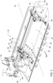
- a harvesting apparatus is generally shown at 20.
- the exemplary embodiment of the harvesting apparatus 20 shown in the Figures is configured for mounting to a forward end of an agricultural machine, such as a self-propelled windrower.
- an agricultural machine such as a self-propelled windrower.
- teachings of this disclosure may be applied to other platforms, such as but not limited to, the harvesting apparatus 20 being configured for connection to a conventional tractor, i.e., the harvesting apparatus 20 being a mower-conditioner drawn behind the tractor.
- the harvesting apparatus 20 is operable to mow and gather standing crop material in a field, condition the cut crop material as it moves through the harvesting apparatus 20 to improve is drying characteristics, and then return the conditioned, cut crop material to the field in a windrow or swath.
- the harvesting apparatus 20 includes a frame 22.
- the frame 22 may include, but is not limited to, the various members, panels, supports, braces, beams, brackets, etc., necessary to support the various components and systems of the harvesting apparatus 20 as described below.
- the frame 22 extends along a central longitudinal axis 24, which generally corresponds to and is parallel with a direction of forward travel 26 of the harvesting apparatus 20 when cutting crop material.
- the frame 22 may be attached to a forward end of the agricultural machine.
- the frame 22 may be attached to the agricultural machine with a drawbar and drawn behind the agricultural machine.
- the harvesting apparatus 20 further includes a cutting mechanism 28.
- the cutting mechanism 28 is coupled to the frame 22, and is operable to cut standing crop material in a field.
- the cutting mechanism 28 may include any mechanism that is capable of cutting the crop material.
- the cutting mechanism 28 is embodied as a rotary disc cutter bar 30.
- the cutting mechanism 28 is not limited to the exemplary embodiment of the rotary disc cutter bar 30. As such, it should be appreciated that the cutting mechanism 28 may vary from the exemplary embodiment shown in the Figures and described herein.
- the exemplary embodiment of the cutting mechanism 28 includes a cutter bar 30 supported by the frame 22.
- the cutter bar 30 extends along an axis that is disposed generally transverse to the direction of forward travel 26 of the harvesting apparatus 20 when cutting the crop material.
- the cutter bar 30 includes a plurality of cutting discs 32 spaced along the cutter bar 30 for rotation about respective vertical axes.
- Each of the cutting discs 32 is coupled to an upright drive shaft to which power is coupled for causing them to rotate in appropriate directions, for delivering cut crop material to an auger 34 disposed rearward of the cutting mechanism 28.
- the auger 34 is rotatably mounted to the frame 22, and passes in front of a crop conditioning system 36.
- the auger 34 is positioned in front of and lower than the crop conditioning system 36.
- the auger 34 includes a central cylindrical drum with a central portion and outer ends.
- the outer ends of the auger 34 include flighting, and a plurality of fins is attached to the central portion.
- the design of the auger 34 enables the delivery of cut crop material into the crop conditioning system 36.
- the cutting mechanism 28 delivers cut crop material to the auger 34, which in turn delivers the cut crop material rearward for further processing by the crop conditioning system 36.
- the conditioned crop material is expelled rearward by the crop conditioning system 36, and is formed into a windrow or swath by upright right and left forming panels (not shown) and a swathboard 38.
- the crop conditioning system 36 includes a crop conditioning element 40 and a hood 42 associated therewith.
- the hood 42 is disposed above the crop conditioning element 40 to form a gap 44 therebetween.
- the crop conditioning element 40 is coupled to the frame 22, and is positioned relative to the frame 22 at a location rearward of the cutting mechanism 28, relative to the direction of forward travel 26 of the harvesting apparatus 20, for receiving cut crop material from the cutting mechanism 28.
- the crop conditioning element 40 is embodied as a crop conditioning impeller.
- the crop conditioning element 40 may be embodied as some other device, such as abut not limited to a crop conditioning roll.
- the crop conditioning element 40 is rotatably driven in a clockwise direction, as viewed on the page of FIGS. 2 and 5-6 , about an impeller axis 46.
- the crop conditioning element 40 e.g., the impeller shown in the Figures
- the crop conditioning element 40 may be formed as an elongated cylindrical drum 48 having a plurality of tines 50 or arms coupled to the drum at a radial distance from the impeller axis 46.
- each of the plurality of tines 50 is disposed substantially tangentially with respect to the cylindrical drum 48.
- the crop conditioning element 40 may be coupled to the harvesting apparatus 20 rearward and upward relative to the auger 34.
- the crop conditioning element 40 is rotatably driven such that the cut crop material is received from the auger 34, and directed around the crop conditioning element 40, between the hood 42 and the crop conditioning element 40, thereby conveying and/or conditioning the crop.
- the terms "crop conditioning" or "conditioned crop material” include the processing of cut crop material to bend, crimp, and/or crack open stem and stalk portions of the cut crop material, and at least partially remove a wax material from the cut crop material, for the purpose of releasing moisture from the cut crop material and reducing dry-down time of the crop material.
- the hood 42 is disposed above the crop conditioning element 40 to form the gap 44 between the hood 42 and the crop conditioning element 40.
- the hood 42 is moveably mounted to the frame 22 above the crop conditioning element 40 for movement relative to the crop conditioning element 40.
- the hood 42 is moveable toward and away from the crop conditioning element 40 for adjusting the gap 44 therebetween.
- adjusting the gap 44 changes the amount of crop conditioning and/or the volume of cut crop material that may be processed. For example, increasing the gap 44 distance for a given volume of cut crop material decreases the friction between hood 42 and the crop conditioning element 40, which decreases the amount of crop conditioning.
- the gap 44 distance may further be adjusted to maintain a given amount of crop conditioning when the volume of cut material passing through the crop conditioning system 36 changes. For example, a higher volume of cut crop material may require that the gap 44 distance be increased to maintain a desired amount of crop conditioning, whereas as lower volume of cut crop material may require that the gap 44 distance be decreased to maintain a desired amount of crop conditioning.
- the swathboard 38 is attached to and moveable with the hood 42.
- the swathboard 38 may be attached to the hood 42 such that the swathboard 38 maintains an operating position relative to the hood 42 during movement with the hood 42 toward and away from the crop conditioning element 40.
- the swathboard 38 is rotatably attached to the hood 42 for movement about a swathboard axis 52, between a plurality of operating positions relative to the hood 42.
- the swathboard 38 is adjustable between the plurality of operating positions, relative to the hood 42, based on how the conditioned crop material is to be discharged rearwardly form the harvesting apparatus 20.
- the swathboard 38 may be adjusted such that the conditioned crop material is discharged laterally rearwardly in a direction opposite the direction of travel of the harvesting apparatus 20.
- the swathboard 38 may be adjusted such that the conditioned crop material is discharged rearwardly and downwardly toward the ground surface.
- the swathboard 38 may further be adjusted to discharge the conditioned crop material based on a desired width and/or depth of the windrow or swath.
- the crop conditioning system 36 includes an adjustment mechanism 54 attached to and moveable with the hood 42.
- the adjustment mechanism 54 is coupled to the swathboard 38, and is operable to rotate the swathboard 38 relative to the hood 42 and about the swathboard axis 52, between each of the plurality of operating positions. Because the adjustment mechanism 54 is attached to and moves with the hood 42, instead of the frame 22, the position of the swathboard 38 relative to the hood 42 remains constant as the hood 42 moves relative to the crop conditioning element 40.
- the harvesting apparatus 20 further includes an actuating system 56 moveably connecting the hood 42 to the frame 22 and configured for moving the hood 42.
- the actuating system 56 is controllable to move the hood 42 toward and away from the crop conditioning element 40.
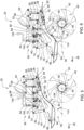
- the hood 42 is shown in a fully raised, first position in FIG. 5 .
- the hood 42 is shown in a fully lowered, second position in FIG. 6 . It should be appreciated that the hood 42 may be positioned in an infinite number of positions between the first position and the second position shown in the Figures.
- the actuating system 56 includes a multiple linkage system for moving the hood 42.
- the actuating system 56 includes a driven lever arm 58, a first pivot assembly 60, and a second pivot assembly 62.
- the driven lever arm 58 is rotatably attached to the frame 22.
- the frame 22 may include multiple different components including one or more brackets.
- the driven lever arm 58 may be attached to a bracket, which is in turn attached to the frame 22.
- the driven lever arm 58 is rotatably attached to the frame 22 for rotation about a lever rotation axis 64.
- the lever rotation axis 64 extends transverse or perpendicular to the central longitudinal axis 24 of the frame 22.
- the driven lever arm 58 includes a first lever connection 66 and a second lever connection 68 positioned opposite each other across the lever rotation axis 64.
- the first lever connection 66 and the second lever connection 68 are arranged approximately one hundred eighty degrees (180°) apart from each other angularly about the lever rotation axis 64.
- the first lever connection 66 and the second lever connection 68 are positioned equidistance from the lever rotation axis 64.
- the first pivot assembly 60 is rotatably attached to the frame 22 for rotation about a first pivot axis 70.
- the first pivot axis 70 extends transverse or perpendicular to the central longitudinal axis 24 of the frame 22 and is parallel with the lever rotation axis 64.
- the frame 22 may include multiple different components including one or more brackets.
- the first pivot assembly 60 may be attached to a bracket, which is in turn attached to the frame 22.
- the first pivot assembly 60 includes a first pivot connection 72 and a second pivot connection 74.
- the first pivot connection 72 is coupled to the first lever connection 66 of the driven lever arm 58.
- a first link 76 interconnects the first lever connection 66 of the driven lever arm 58 and the first pivot connection 72 of the first pivot assembly 60.
- the first link 76 is rotatably attached to both the driven lever arm 58 and the first pivot assembly 60 at the first lever connection 66 and the first pivot connection 72 respectively.
- the second pivot connection 74 is coupled to a first lift location 78 of the hood 42.
- a third link 80 interconnects the second pivot connection 74 of the first pivot assembly 60 and the first lift connection of the hood 42.
- the third link 80 is rotatably attached to both the first pivot assembly 60 and the hood 42 at the second pivot connection 74 and the first lift connection respectively.
- the second pivot assembly 62 is rotatably attached to the frame 22 for rotation about a second pivot axis 82.
- the second pivot axis 82 extends transverse or perpendicular to the central longitudinal axis 24 of the frame 22 and is parallel with the lever rotation axis 64 and the first pivot axis 70.
- the frame 22 may include multiple different components including one or more brackets.
- the second pivot assembly 62 may be attached to a bracket, which is in turn attached to the frame 22.
- the second pivot assembly 62 includes a third pivot connection 84 and a fourth pivot connection 86.
- the third pivot connection 84 is coupled to the second lever connection 68 of the driven lever arm 58.
- a second link 88 interconnects the second lever connection 68 of the driven lever arm 58 and the third pivot connection 84 of the second pivot assembly 62.
- the second link 88 is rotatably attached to both the driven lever arm 58 and the second pivot assembly 62 at the second lever connection 68 and the third pivot connection 84 respectively.
- the fourth pivot connection 86 is coupled to a second lift location of the hood 42.
- a fourth link 92 interconnects the fourth pivot connection 86 of the second pivot assembly 62 and the second lift connection 90 of the hood 42.
- the fourth link 92 is rotatably attached to both the second pivot assembly 62 and the hood 42 at the fourth pivot connection 86 and the second lift connection 90 respectively.
- the driven lever arm 58 is positioned between the first pivot assembly 60 and the second pivot assembly 62 along the central longitudinal axis 24 of the frame 22.
- the first pivot assembly 60 is positioned forward of the driven lever arm 58 along the central longitudinal axis 24 of the frame 22.
- the driven lever arm 58 is positioned forward of the second pivot assembly 62 along the central longitudinal axis 24 of the frame 22.
- the lever rotation axis 64 is equidistant from the first pivot axis 70 and the second pivot axis 82 along the central longitudinal axis 24 of the frame 22.
- the hood 42 includes the first lift connection and the second lift connection 90.
- the first lift connection is positioned forward of the second lift connection 90 along the central longitudinal axis 24 of the frame 22 relative to the direction of forward travel 26.
- the first pivot assembly 60 is positioned forward of the second pivot assembly 62 along the central longitudinal axis 24 of the frame 22 relative to the direction of forward travel 26.
- the third link 80 which connects the first pivot assembly 60 and the first lift location 78, extends in a generally vertical orientation that is angled slightly forward.
- the fourth link 92 which connects the second pivot assembly 62 and the second lift connection 90, extends in a generally vertical orientation that is angled slightly rearward. As such, the third link 80 and the fourth link 92 do not cross and are not directly connected or attached to each other.
- a bar 94 extends between and interconnects the hood 42 and the frame 22.
- the bar 94 is attached to the hood 42 at a first bar mount 96 and is attached to the frame 22 at a second bar mount 98.
- the bar 94 is pivotably attached to the hood 42 and the frame 22 at the first bar mount 96 and the second bar mount 98 respectively.
- the bar 94 is a rigid structure that is positioned relative to the other components of the actuating system 56 to limit forward and/or rearward movement of the hood 42 relative to the frame 22.
- the first bar mount 96 is positioned forward of the second bar mount 98 along the central longitudinal axis 24 of the frame 22.
- first bar mount 96 is positioned forward of the first lift connection along the central longitudinal axis 24 of the frame 22 relative to the direction of forward travel 26.
- the second bar mount 98 may be positioned between the first lift connection and the second lift connection 90 along the central longitudinal axis 24 of the frame 22. In the example implementation shown in the Figures, the second bar mount 98 is positioned vertically beneath the second pivot axis 82.
- An actuator 100 is coupled to the driven lever arm 58.
- the actuator 100 is operable to rotate the driven lever arm 58 in at least one of a first rotational direction 102 or a second rotational direction 104.
- the second rotational direction 104 is opposite to the first rotational direction 102.
- the first rotational direction 102 may be considered a clockwise direction as viewed on the page of the Figures
- the second rotational direction 104 may be considered a counterclockwise direction as viewed on the page of the Figures.
- the first rotational direction 102 and the second rotational direction 104 may be defined differently than the example implementation described herein.
- the actuator 100 may include, but is not limited to, an electric motor, a hydraulic motor, one or more hydraulic cylinders, or some other device or system capable of rotating the driven lever arm 58 about the lever rotation axis 64.
- the actuator 100 includes a manually operated hand crank that is connected to a drive shaft 106. Rotation of the hand crank rotates the drive shaft 106 about the lever rotation axis 64.
- the drive shaft 106 interconnects the actuator 100, e.g., the hand crank, and the driven lever arm 58 and is operable to transmit torque between the actuator 100 and the driven lever arm 58.
- the example implementation includes the hand crank coupled to the drive shaft 106, it should be appreciated that other implementations may include different implementations of the actuator 100 coupled to the hand crank, such as but not limited to, an electric motor, a hydraulic motor, one or more hydraulic cylinders, etc.
- the first lever connection 66 and the first pivot connection 72 are positioned relative to the lever rotation axis 64 and the first pivot axis 70 respectively such that rotation of the driven lever arm 58 in the first rotational direction 102 rotates the first pivot assembly 60 in the first rotational direction 102, and rotation of the driven lever arm 58 in the second rotational direction 104 rotates the first pivot assembly 60 in the second rotational direction 104.
- the second lever connection 68 and the third pivot connection 84 are positioned relative to the lever rotation axis 64 and the second pivot axis 82 respectively such that rotation of the driven lever arm 58 in the first rotational direction 102 rotates the second pivot assembly 62 in the second rotational direction 104, and rotation of the driven lever arm 58 in the second rotational direction 104 rotates the second pivot assembly 62 in the first rotational direction 102.
- the second pivot connection 74 is positioned relative to the first pivot axis 70 and the first pivot connection 72 to travel in a substantially upward vertical direction in response to rotation of the first pivot assembly 60 in the first rotational direction 102, and travel in a substantially downward vertical direction in response to rotation of the first pivot assembly 60 in the second rotational direction 104.
- the fourth pivot connection 86 is positioned relative to the second pivot axis 82 and the third pivot connection 84 to travel in the substantially upward vertical direction in response to rotation of the second pivot assembly 62 in the second rotational direction 104, and travel in the substantially downward vertical direction in response to rotation of the second pivot assembly 62 in the first rotational direction 102.
- Rotation of the first pivot assembly 60 about the first pivot axis 70 in the first rotational direction 102 and rotation of the second pivot assembly 62 about the second pivot axis 82 in the second rotational direction 104 moves the hood 42 away from the crop conditioning element 40.
- Rotation of the first pivot assembly 60 about the first pivot axis 70 in the second rotational direction 104 and rotation of the second pivot assembly 62 about the second pivot axis 82 in the first rotational direction 102 moves the hood 42 toward the crop condition element.
- the positioning of the components of the actuating system 56 enable the hood 42 to move relative to the crop conditioning element 40 while substantially maintaining the same orientation of the hood 42 relative to the crop conditioning element 40. In other words, the hood 42 may move generally vertically up or down without significantly swinging or rotating.
- hood 42 This enables the hood 42 to maintain its positional orientation relative to the crop conditioning element 40.
- the location of the pinch point 108 between the hood 42 and the crop conditioning element 40, as well as the entrance angle 110 into the gap 44 remain substantially constant, thereby providing consistent conditioning of the crop material as the gap 44 is adjusted.
Landscapes
- Life Sciences & Earth Sciences (AREA)
- Environmental Sciences (AREA)
- Harvester Elements (AREA)
- Harvesting Machines For Specific Crops (AREA)
- Agricultural Machines (AREA)
Claims (13)
- Ernteeinrichtung für eine landwirtschaftliche Maschine, wobei die Ernteeinrichtung (20) Folgendes umfasst:einen Rahmen (22);einen Schneidmechanismus (28), gekoppelt mit dem Rahmen (22) und betreibbar zum Schneiden von Erntegutmaterial;ein Erntegutkonditionierungselement (40), gekoppelt mit dem Rahmen (22);eine Haube (42), bewegbar bezüglich des Erntegutkonditionierungselements (40), wobei die Haube (42) eine erste Hubverbindung (78) und eine zweite Hubverbindung (90) umfasst;ein Betätigungssystem (56), das die Haube (42) bewegbar mit dem Rahmen (22) verbindet, wobei das Betätigungssystem (56) Folgendes umfasst:einen angetriebenen Hebelarm (58), der rotierbar am Rahmen (22) befestigt ist zur Rotation um eine Hebelrotationsachse (64), wobei der angetriebene Hebelarm (58) eine erste Hebelverbindung (66) und eine zweite Hebelverbindung (68) umfasst, die bezüglich der Hebelrotationsachse (64) einander gegenüberliegend positioniert sind;eine erste Schwenkanordnung (60), die rotierbar am Rahmen (22) befestigt ist zur Rotation um eine erste Schwenkachse (70), wobei die erste Schwenkanordnung (60) eine erste Schwenkverbindung (72), die mit der ersten Hebelverbindung (66) des angetriebenen Hebelarms (58) verbunden ist, und eine zweite Schwenkverbindung (74), die mit der ersten Hubverbindung (78) der Haube (42) gekoppelt ist, umfasst; undeine zweite Schwenkanordnung (62), die rotierbar am Rahmen (22) befestigt ist zur Rotation um eine zweite Schwenkachse (82), wobei die zweite Schwenkanordnung (62) eine dritte Schwenkverbindung (84), die mit der zweiten Hebelverbindung (68) des angetriebenen Hebelarms (58) gekoppelt ist, und eine vierte Schwenkverbindung (86), die mit der zweiten Hubposition der Haube (42) gekoppelt ist, umfasst, und wobei die Ernteeinrichtung ferner einen Aktuator (100) umfasst, der mit dem angetriebenen Hebelarm (58) gekoppelt ist und betreibbar ist zum Rotieren des angetriebenen Hebelarms (58) in zumindest einer aus einer ersten Rotationsrichtung (102) oder einer zweiten Rotationsrichtung (104), dadurch gekennzeichnet, dass die Ernteeinrichtung ferner ein drittes Verbindungsglied (80) umfasst, das die zweite Schwenkverbindung (74) der ersten Schwenkanordnung (60) und die erste Hubverbindung (78) der Haube (42) miteinander verbindet.
- Ernteeinrichtung nach Anspruch 1, ferner umfassend ein erstes Verbindungsglied (76), das die erste Hebelverbindung (66) des angetriebenen Hebelarms (58) und die erste Schwenkverbindung (72) der ersten Schwenkanordnung (60) miteinander verbindet.
- Ernteeinrichtung nach Anspruch 1 oder 2, ferner umfassend ein zweites Verbindungsglied (88), das die zweite Hebelverbindung (68) des angetriebenen Hebelarms (58) und die dritte Schwenkverbindung (84) der zweiten Schwenkanordnung (62) miteinander verbindet.
- Ernteeinrichtung nach zumindest einem der vorhergehenden Ansprüche, ferner umfassend ein viertes Verbindungsglied (92), das die vierte Schwenkverbindung (86) der zweiten Schwenkanordnung (62) und die zweite Hubverbindung (90) der Haube (42) miteinander verbindet.
- Ernteeinrichtung nach zumindest einem der vorhergehenden Ansprüche, wobei die erste Hubverbindung (78) entlang einer mittleren Längsachse (24) des Rahmens (22) vor der zweiten Hubverbindung (90) bezüglich einer Vorwärtsbewegungsrichtung (26) positioniert ist.
- Ernteeinrichtung nach zumindest einem der vorhergehenden Ansprüche, wobei die erste Schwenkanordnung (60) entlang der mittleren Längsachse (24) des Rahmens (22) vor der zweiten Schwenkanordnung (62) bezüglich der Vorwärtsbewegungsrichtung (26) positioniert ist.
- Ernteeinrichtung nach zumindest einem der vorhergehenden Ansprüche, wobei die erste Hebelverbindung (66) und die erste Schwenkverbindung (72) bezüglich der Hebelrotationsachse (64) bzw. der ersten Schwenkachse (70) so positioniert sind, dass Rotation des angetriebenen Hebelarms (58) in einer ersten Rotationsrichtung (102) die erste Schwenkanordnung (60) in der ersten Rotationsrichtung (102) rotiert und Rotation des angetriebenen Hebelarms (58) in einer zweiten Rotationsrichtung (104) die erste Schwenkanordnung (60) in der zweiten Rotationsrichtung (104) rotiert.
- Ernteeinrichtung nach Anspruch 7, wobei die zweite Hebelverbindung (68) und die dritte Schwenkverbindung (84) bezüglich der Hebelrotationsachse (64) bzw. der zweiten Schwenkachse (82) so positioniert sind, dass Rotation des angetriebenen Hebelarms (58) in der ersten Rotationsrichtung (102) die zweite Schwenkanordnung (62) in der zweiten Rotationsrichtung (104) rotiert und Rotation des angetriebenen Hebelarms (58) in einer zweiten Rotationsrichtung (104) die zweite Schwenkanordnung (62) in der ersten Rotationsrichtung (102) rotiert.
- Ernteeinrichtung nach zumindest einem der vorhergehenden Ansprüche, ferner umfassend eine Stange (94), die die Haube (42) und den Rahmen (22) miteinander verbindet.
- Ernteeinrichtung nach Anspruch 9, wobei die Stange (94) an einer ersten Stangenhalterung (96) an der Haube (42) befestigt ist und wobei die Stange (94) an einer zweiten Stangenhalterung (98) am Rahmen (22) befestigt ist.
- Ernteeinrichtung nach Anspruch 10, wobei die erste Stangenhalterung (96) entlang einer mittleren Längsachse (24) des Rahmens (22) vor der zweiten Stangenhalterung (98) bezüglich einer Vorwärtsbewegungsrichtung (26) positioniert ist.
- Ernteeinrichtung nach Anspruch 10, wobei die erste Stangenhalterung (96) entlang einer mittleren Längsachse (24) des Rahmens (22) vor der ersten Hubverbindung (78) bezüglich einer Vorwärtsbewegungsrichtung (26) positioniert ist.
- Ernteeinrichtung nach zumindest einem der vorhergehenden Ansprüche, wobei die zweite Schwenkverbindung (74) bezüglich der ersten Schwenkachse (70) und der ersten Schwenkverbindung (72) positioniert ist, um sich im Wesentlichen aufwärts in einer vertikalen Richtung zu bewegen in Reaktion auf Rotation der ersten Schwenkanordnung (60) in einer ersten Rotationsrichtung (102), und sich im Wesentlichen abwärts in einer vertikalen Richtung zu bewegen in Reaktion auf Rotation der ersten Schwenkanordnung (60) in einer zweiten Rotationsrichtung (104).
Applications Claiming Priority (1)
| Application Number | Priority Date | Filing Date | Title |
|---|---|---|---|
| US17/155,146 US11925144B2 (en) | 2021-01-22 | 2021-01-22 | Mower conditioner impeller hood actuating mechanism |
Publications (2)
| Publication Number | Publication Date |
|---|---|
| EP4032391A1 EP4032391A1 (de) | 2022-07-27 |
| EP4032391B1 true EP4032391B1 (de) | 2024-12-11 |
Family
ID=80112330
Family Applications (1)
| Application Number | Title | Priority Date | Filing Date |
|---|---|---|---|
| EP22151478.9A Active EP4032391B1 (de) | 2021-01-22 | 2022-01-14 | Betätigungsmechanismus für eine mähwerklaufradhaube |
Country Status (3)
| Country | Link |
|---|---|
| US (1) | US11925144B2 (de) |
| EP (1) | EP4032391B1 (de) |
| CA (1) | CA3142848A1 (de) |
Family Cites Families (14)
| Publication number | Priority date | Publication date | Assignee | Title |
|---|---|---|---|---|
| CH541271A (de) * | 1970-07-24 | 1973-09-15 | Bucher Guyer Ag Masch | Konditionierungsmaschine für landwirtschaftliches Halmgut |
| US4233803A (en) * | 1978-05-04 | 1980-11-18 | Deere & Company | Adjustable conditioning plate for an impeller mower-conditioner |
| DE3048569C2 (de) * | 1980-12-22 | 1986-03-27 | Bucher-Guyer AG Maschinenfabrik, Niederweningen, Zürich | Vorrichtung zum Aufbereiten geschnittenen Halmgutes |
| DE3167560D1 (en) * | 1981-05-06 | 1985-01-17 | Deere John | Mower-conditioner |
| DE3167409D1 (en) * | 1981-05-06 | 1985-01-10 | Deere John | Mower-conditioner |
| US4539798A (en) * | 1982-03-26 | 1985-09-10 | National Research Development Corporation | Apparatus and method for conveying and/or treating crop |
| US4720962A (en) * | 1982-07-29 | 1988-01-26 | National Research Development Corporation | Apparatus for picking up and conveying crop or other material |
| DE3446321A1 (de) * | 1984-12-19 | 1986-06-19 | Claas Saulgau GmbH, 7968 Saulgau | Landwirtschaftliches geraet fuer die gras-conditionierung |
| FR2767633B1 (fr) * | 1997-09-02 | 1999-10-08 | Kuhn Sa | Dispositif de conditionnement ameliore, machine pour le conditionnement et faucheuse conditionneuse comportant un tel dispositif |
| DE19826976A1 (de) | 1998-06-18 | 1999-12-23 | Niemeyer Landmasch Gmbh | Aufbereiter für Kreiselmäher |
| FR2855012B1 (fr) | 2003-05-23 | 2006-06-02 | Kuhn Sa | Dispositif de traitement du fourrage muni de deux elements de guidage |
| DE102006056050A1 (de) * | 2006-11-28 | 2008-06-05 | Deere & Company, Moline | Gutführvorrichtung |
| GB2560997A (en) * | 2017-03-31 | 2018-10-03 | Kverneland Group Kerteminde As | Dual conditioner plate |
| US11096329B2 (en) * | 2019-05-31 | 2021-08-24 | Deere & Company | Crop conditioner hood with integrated swathboard |
-
2021
- 2021-01-22 US US17/155,146 patent/US11925144B2/en active Active
- 2021-12-17 CA CA3142848A patent/CA3142848A1/en active Pending
-
2022
- 2022-01-14 EP EP22151478.9A patent/EP4032391B1/de active Active
Also Published As
| Publication number | Publication date |
|---|---|
| EP4032391A1 (de) | 2022-07-27 |
| US20220232776A1 (en) | 2022-07-28 |
| CA3142848A1 (en) | 2022-07-22 |
| US11925144B2 (en) | 2024-03-12 |
Similar Documents
| Publication | Publication Date | Title |
|---|---|---|
| US11096329B2 (en) | Crop conditioner hood with integrated swathboard | |
| US6591598B2 (en) | Crop harvesting header with cam controlled movement of the reel fingers | |
| AU2018329221B2 (en) | Crop harvesting header with cam adjustment component responsive to reel movement | |
| US7874133B2 (en) | Forage harvester having a blower | |
| US6988352B2 (en) | Accelerator and crop processor movement | |
| WO2014180788A1 (en) | Chopper/blower arrangement for a header used on an agricultural harvester | |
| US3722194A (en) | Converging reel assembly having a tine control mechanism incorporated therein | |
| AU2019272023B2 (en) | Crop harvesting reel with an end shield plate and fingers for guiding crop | |
| EP4032391B1 (de) | Betätigungsmechanismus für eine mähwerklaufradhaube | |
| US11343968B2 (en) | Crop harvesting reel with an end shield plate and fingers for guiding crop | |
| EP3695704B1 (de) | Laufradkonditionierer mit einer zinkenvorrichtung mit begrenzter seitlicher bewegung | |
| US3438182A (en) | Forage harvester | |
| EP0908088B1 (de) | Neigungseinrichtung für eine pendelnd gelagerte Schwadaufnehmer | |
| US6971439B1 (en) | Protective screen arrangement for an agricultural machine | |
| EP3669635B1 (de) | Mähdrescherschneidwerk mit einstellbarer haspel | |
| US20240099194A1 (en) | Mower-conditioner having fins on control surfaces | |
| EP4552472A1 (de) | Nachlaufradschutz | |
| US3422606A (en) | Crop conditioner attachment for a windrower | |
| CA3072840C (en) | Crop harvesting header with cam controlled movement of the reel fingers | |
| CA3000245A1 (en) | A header with a crop divider disc |
Legal Events
| Date | Code | Title | Description |
|---|---|---|---|
| PUAI | Public reference made under article 153(3) epc to a published international application that has entered the european phase |
Free format text: ORIGINAL CODE: 0009012 |
|
| STAA | Information on the status of an ep patent application or granted ep patent |
Free format text: STATUS: THE APPLICATION HAS BEEN PUBLISHED |
|
| AK | Designated contracting states |
Kind code of ref document: A1 Designated state(s): AL AT BE BG CH CY CZ DE DK EE ES FI FR GB GR HR HU IE IS IT LI LT LU LV MC MK MT NL NO PL PT RO RS SE SI SK SM TR |
|
| STAA | Information on the status of an ep patent application or granted ep patent |
Free format text: STATUS: REQUEST FOR EXAMINATION WAS MADE |
|
| 17P | Request for examination filed |
Effective date: 20230127 |
|
| RBV | Designated contracting states (corrected) |
Designated state(s): AL AT BE BG CH CY CZ DE DK EE ES FI FR GB GR HR HU IE IS IT LI LT LU LV MC MK MT NL NO PL PT RO RS SE SI SK SM TR |
|
| GRAP | Despatch of communication of intention to grant a patent |
Free format text: ORIGINAL CODE: EPIDOSNIGR1 |
|
| STAA | Information on the status of an ep patent application or granted ep patent |
Free format text: STATUS: GRANT OF PATENT IS INTENDED |
|
| INTG | Intention to grant announced |
Effective date: 20240719 |
|
| GRAS | Grant fee paid |
Free format text: ORIGINAL CODE: EPIDOSNIGR3 |
|
| GRAA | (expected) grant |
Free format text: ORIGINAL CODE: 0009210 |
|
| STAA | Information on the status of an ep patent application or granted ep patent |
Free format text: STATUS: THE PATENT HAS BEEN GRANTED |
|
| REG | Reference to a national code |
Ref country code: DE Ref legal event code: R081 Ref document number: 602022008497 Country of ref document: DE Owner name: DEERE & COMPANY, MOLINE, US Free format text: FORMER OWNER: DEERE & COMPANY, MOLINE, US |
|
| AK | Designated contracting states |
Kind code of ref document: B1 Designated state(s): AL AT BE BG CH CY CZ DE DK EE ES FI FR GB GR HR HU IE IS IT LI LT LU LV MC MK MT NL NO PL PT RO RS SE SI SK SM TR |
|
| REG | Reference to a national code |
Ref country code: GB Ref legal event code: FG4D |
|
| REG | Reference to a national code |
Ref country code: CH Ref legal event code: EP |
|
| REG | Reference to a national code |
Ref country code: IE Ref legal event code: FG4D |
|
| REG | Reference to a national code |
Ref country code: DE Ref legal event code: R096 Ref document number: 602022008497 Country of ref document: DE |
|
| REG | Reference to a national code |
Ref country code: LT Ref legal event code: MG9D |
|
| PG25 | Lapsed in a contracting state [announced via postgrant information from national office to epo] |
Ref country code: HR Free format text: LAPSE BECAUSE OF FAILURE TO SUBMIT A TRANSLATION OF THE DESCRIPTION OR TO PAY THE FEE WITHIN THE PRESCRIBED TIME-LIMIT Effective date: 20241211 |
|
| PGFP | Annual fee paid to national office [announced via postgrant information from national office to epo] |
Ref country code: DE Payment date: 20250227 Year of fee payment: 4 |
|
| PG25 | Lapsed in a contracting state [announced via postgrant information from national office to epo] |
Ref country code: FI Free format text: LAPSE BECAUSE OF FAILURE TO SUBMIT A TRANSLATION OF THE DESCRIPTION OR TO PAY THE FEE WITHIN THE PRESCRIBED TIME-LIMIT Effective date: 20241211 |
|
| PG25 | Lapsed in a contracting state [announced via postgrant information from national office to epo] |
Ref country code: BG Free format text: LAPSE BECAUSE OF FAILURE TO SUBMIT A TRANSLATION OF THE DESCRIPTION OR TO PAY THE FEE WITHIN THE PRESCRIBED TIME-LIMIT Effective date: 20241211 |
|
| REG | Reference to a national code |
Ref country code: NL Ref legal event code: MP Effective date: 20241211 |
|
| PG25 | Lapsed in a contracting state [announced via postgrant information from national office to epo] |
Ref country code: ES Free format text: LAPSE BECAUSE OF FAILURE TO SUBMIT A TRANSLATION OF THE DESCRIPTION OR TO PAY THE FEE WITHIN THE PRESCRIBED TIME-LIMIT Effective date: 20241211 |
|
| PG25 | Lapsed in a contracting state [announced via postgrant information from national office to epo] |
Ref country code: NO Free format text: LAPSE BECAUSE OF FAILURE TO SUBMIT A TRANSLATION OF THE DESCRIPTION OR TO PAY THE FEE WITHIN THE PRESCRIBED TIME-LIMIT Effective date: 20250311 |
|
| PG25 | Lapsed in a contracting state [announced via postgrant information from national office to epo] |
Ref country code: LV Free format text: LAPSE BECAUSE OF FAILURE TO SUBMIT A TRANSLATION OF THE DESCRIPTION OR TO PAY THE FEE WITHIN THE PRESCRIBED TIME-LIMIT Effective date: 20241211 Ref country code: GR Free format text: LAPSE BECAUSE OF FAILURE TO SUBMIT A TRANSLATION OF THE DESCRIPTION OR TO PAY THE FEE WITHIN THE PRESCRIBED TIME-LIMIT Effective date: 20250312 |
|
| PGFP | Annual fee paid to national office [announced via postgrant information from national office to epo] |
Ref country code: FR Payment date: 20250225 Year of fee payment: 4 |
|
| PG25 | Lapsed in a contracting state [announced via postgrant information from national office to epo] |
Ref country code: RS Free format text: LAPSE BECAUSE OF FAILURE TO SUBMIT A TRANSLATION OF THE DESCRIPTION OR TO PAY THE FEE WITHIN THE PRESCRIBED TIME-LIMIT Effective date: 20250311 |
|
| PG25 | Lapsed in a contracting state [announced via postgrant information from national office to epo] |
Ref country code: NL Free format text: LAPSE BECAUSE OF FAILURE TO SUBMIT A TRANSLATION OF THE DESCRIPTION OR TO PAY THE FEE WITHIN THE PRESCRIBED TIME-LIMIT Effective date: 20241211 |
|
| REG | Reference to a national code |
Ref country code: AT Ref legal event code: MK05 Ref document number: 1749557 Country of ref document: AT Kind code of ref document: T Effective date: 20241211 |
|
| PG25 | Lapsed in a contracting state [announced via postgrant information from national office to epo] |
Ref country code: SM Free format text: LAPSE BECAUSE OF FAILURE TO SUBMIT A TRANSLATION OF THE DESCRIPTION OR TO PAY THE FEE WITHIN THE PRESCRIBED TIME-LIMIT Effective date: 20241211 |
|
| PG25 | Lapsed in a contracting state [announced via postgrant information from national office to epo] |
Ref country code: PL Free format text: LAPSE BECAUSE OF FAILURE TO SUBMIT A TRANSLATION OF THE DESCRIPTION OR TO PAY THE FEE WITHIN THE PRESCRIBED TIME-LIMIT Effective date: 20241211 |
|
| PG25 | Lapsed in a contracting state [announced via postgrant information from national office to epo] |
Ref country code: IS Free format text: LAPSE BECAUSE OF FAILURE TO SUBMIT A TRANSLATION OF THE DESCRIPTION OR TO PAY THE FEE WITHIN THE PRESCRIBED TIME-LIMIT Effective date: 20250411 |
|
| PG25 | Lapsed in a contracting state [announced via postgrant information from national office to epo] |
Ref country code: PT Free format text: LAPSE BECAUSE OF FAILURE TO SUBMIT A TRANSLATION OF THE DESCRIPTION OR TO PAY THE FEE WITHIN THE PRESCRIBED TIME-LIMIT Effective date: 20250411 |
|
| PG25 | Lapsed in a contracting state [announced via postgrant information from national office to epo] |
Ref country code: EE Free format text: LAPSE BECAUSE OF FAILURE TO SUBMIT A TRANSLATION OF THE DESCRIPTION OR TO PAY THE FEE WITHIN THE PRESCRIBED TIME-LIMIT Effective date: 20241211 |
|
| PG25 | Lapsed in a contracting state [announced via postgrant information from national office to epo] |
Ref country code: AT Free format text: LAPSE BECAUSE OF FAILURE TO SUBMIT A TRANSLATION OF THE DESCRIPTION OR TO PAY THE FEE WITHIN THE PRESCRIBED TIME-LIMIT Effective date: 20241211 Ref country code: RO Free format text: LAPSE BECAUSE OF FAILURE TO SUBMIT A TRANSLATION OF THE DESCRIPTION OR TO PAY THE FEE WITHIN THE PRESCRIBED TIME-LIMIT Effective date: 20241211 |
|
| PG25 | Lapsed in a contracting state [announced via postgrant information from national office to epo] |
Ref country code: SK Free format text: LAPSE BECAUSE OF FAILURE TO SUBMIT A TRANSLATION OF THE DESCRIPTION OR TO PAY THE FEE WITHIN THE PRESCRIBED TIME-LIMIT Effective date: 20241211 |
|
| PG25 | Lapsed in a contracting state [announced via postgrant information from national office to epo] |
Ref country code: CZ Free format text: LAPSE BECAUSE OF FAILURE TO SUBMIT A TRANSLATION OF THE DESCRIPTION OR TO PAY THE FEE WITHIN THE PRESCRIBED TIME-LIMIT Effective date: 20241211 |
|
| PG25 | Lapsed in a contracting state [announced via postgrant information from national office to epo] |
Ref country code: IT Free format text: LAPSE BECAUSE OF FAILURE TO SUBMIT A TRANSLATION OF THE DESCRIPTION OR TO PAY THE FEE WITHIN THE PRESCRIBED TIME-LIMIT Effective date: 20241211 |
|
| REG | Reference to a national code |
Ref country code: CH Ref legal event code: PL |
|
| PG25 | Lapsed in a contracting state [announced via postgrant information from national office to epo] |
Ref country code: SE Free format text: LAPSE BECAUSE OF FAILURE TO SUBMIT A TRANSLATION OF THE DESCRIPTION OR TO PAY THE FEE WITHIN THE PRESCRIBED TIME-LIMIT Effective date: 20241211 |
|
| REG | Reference to a national code |
Ref country code: DE Ref legal event code: R097 Ref document number: 602022008497 Country of ref document: DE |
|
| PG25 | Lapsed in a contracting state [announced via postgrant information from national office to epo] |
Ref country code: MC Free format text: LAPSE BECAUSE OF FAILURE TO SUBMIT A TRANSLATION OF THE DESCRIPTION OR TO PAY THE FEE WITHIN THE PRESCRIBED TIME-LIMIT Effective date: 20241211 Ref country code: LU Free format text: LAPSE BECAUSE OF NON-PAYMENT OF DUE FEES Effective date: 20250114 |
|
| PG25 | Lapsed in a contracting state [announced via postgrant information from national office to epo] |
Ref country code: DK Free format text: LAPSE BECAUSE OF FAILURE TO SUBMIT A TRANSLATION OF THE DESCRIPTION OR TO PAY THE FEE WITHIN THE PRESCRIBED TIME-LIMIT Effective date: 20241211 |
|
| PG25 | Lapsed in a contracting state [announced via postgrant information from national office to epo] |
Ref country code: BE Free format text: LAPSE BECAUSE OF NON-PAYMENT OF DUE FEES Effective date: 20250131 |
|
| PLBE | No opposition filed within time limit |
Free format text: ORIGINAL CODE: 0009261 |
|
| STAA | Information on the status of an ep patent application or granted ep patent |
Free format text: STATUS: NO OPPOSITION FILED WITHIN TIME LIMIT |
|
| PG25 | Lapsed in a contracting state [announced via postgrant information from national office to epo] |
Ref country code: CH Free format text: LAPSE BECAUSE OF NON-PAYMENT OF DUE FEES Effective date: 20250131 |
|
| REG | Reference to a national code |
Ref country code: BE Ref legal event code: MM Effective date: 20250131 |
|
| 26N | No opposition filed |
Effective date: 20250912 |
|
| PG25 | Lapsed in a contracting state [announced via postgrant information from national office to epo] |
Ref country code: IE Free format text: LAPSE BECAUSE OF NON-PAYMENT OF DUE FEES Effective date: 20250114 |