EP4032385B1 - Elektrischer überspannungsschutz für ein roboterwerkzeugsystem für den aussenbereich - Google Patents
Elektrischer überspannungsschutz für ein roboterwerkzeugsystem für den aussenbereich Download PDFInfo
- Publication number
- EP4032385B1 EP4032385B1 EP22152149.5A EP22152149A EP4032385B1 EP 4032385 B1 EP4032385 B1 EP 4032385B1 EP 22152149 A EP22152149 A EP 22152149A EP 4032385 B1 EP4032385 B1 EP 4032385B1
- Authority
- EP
- European Patent Office
- Prior art keywords
- work tool
- robotic work
- activation
- charging
- charging station
- Prior art date
- Legal status (The legal status is an assumption and is not a legal conclusion. Google has not performed a legal analysis and makes no representation as to the accuracy of the status listed.)
- Active
Links
Images


Classifications
-
- H—ELECTRICITY
- H02—GENERATION; CONVERSION OR DISTRIBUTION OF ELECTRIC POWER
- H02H—EMERGENCY PROTECTIVE CIRCUIT ARRANGEMENTS
- H02H1/00—Details of emergency protective circuit arrangements
- H02H1/04—Arrangements for preventing response to transient abnormal conditions, e.g. to lightning or to short duration over voltage or oscillations; Damping the influence of DC component by short circuits in AC networks
-
- A—HUMAN NECESSITIES
- A01—AGRICULTURE; FORESTRY; ANIMAL HUSBANDRY; HUNTING; TRAPPING; FISHING
- A01D—HARVESTING; MOWING
- A01D34/00—Mowers; Mowing apparatus of harvesters
- A01D34/006—Control or measuring arrangements
- A01D34/008—Control or measuring arrangements for automated or remotely controlled operation
-
- B—PERFORMING OPERATIONS; TRANSPORTING
- B60—VEHICLES IN GENERAL
- B60L—PROPULSION OF ELECTRICALLY-PROPELLED VEHICLES; SUPPLYING ELECTRIC POWER FOR AUXILIARY EQUIPMENT OF ELECTRICALLY-PROPELLED VEHICLES; ELECTRODYNAMIC BRAKE SYSTEMS FOR VEHICLES IN GENERAL; MAGNETIC SUSPENSION OR LEVITATION FOR VEHICLES; MONITORING OPERATING VARIABLES OF ELECTRICALLY-PROPELLED VEHICLES; ELECTRIC SAFETY DEVICES FOR ELECTRICALLY-PROPELLED VEHICLES
- B60L53/00—Methods of charging batteries, specially adapted for electric vehicles; Charging stations or on-board charging equipment therefor; Exchange of energy storage elements in electric vehicles
- B60L53/60—Monitoring or controlling charging stations
-
- H—ELECTRICITY
- H02—GENERATION; CONVERSION OR DISTRIBUTION OF ELECTRIC POWER
- H02H—EMERGENCY PROTECTIVE CIRCUIT ARRANGEMENTS
- H02H3/00—Emergency protective circuit arrangements for automatic disconnection directly responsive to an undesired change from normal electric working condition with or without subsequent reconnection ; integrated protection
- H02H3/02—Details
- H02H3/021—Details concerning the disconnection itself, e.g. at a particular instant, particularly at zero value of current, disconnection in a predetermined order
Definitions
- the present disclosure relates to outdoor robotic work tool system with an outdoor robotic work tool and a work tool charging station, and in particular high voltage electrical surge protections for the outdoor robotic work tool and the work tool charging station with associated electrical components, especially electrical surges which are due to one or more lightning strikes during a thunder storm.
- the outdoor robotic work tool can for example be constituted by a robotic lawn mower.
- Automated or robotic power tools such as robotic lawn mowers are becoming increasingly more popular.
- a work area such as a garden
- the work area can be enclosed by a boundary wire with the purpose of keeping the robotic lawn mower inside the work area.
- An electric control signal may be transmitted through the boundary wire thereby generating an (electro-) magnetic field emanating from the boundary wire.
- the robotic lawn mower is typically arranged with one or more sensors adapted to sense the control signal.
- Other types of navigation systems can be used instead of, or in combination with a boundary wire.
- Such navigation systems can for example be based on satellite navigation systems and/or local radio beacons or image processing such as Visual Simultaneous Localization and Mapping (VSLAM).
- VSLAM Visual Simultaneous Localization and Mapping
- the robotic lawn mower can then cut grass on a user's lawn automatically and can be charged automatically without intervention of the user, and no longer needs to be manually managed after being set once.
- the robotic lawn mower typically comprises charging skids for contacting corresponding contact plates in a charging station when docking into the charging station for receiving a charging current through, and possibly also for transferring information by means of electrical communication between the charging station and the robotic lawn mower.
- a lightning strike may damage robotic lawn mower equipment such as the robotic lawn mower itself, especially during charging, power supply units, loop generators and other lawn mower system electronics. This is due to high voltage electrical surges, inflicted from lightning strikes, entering the robotic lawn mower equipment via the electrical mains and/or the boundary wire if used.
- the document SE 539127 discloses a surge arrester for a robotic lawn mower assembly, comprising a grounding rod and protection circuitry adapted to lead high voltage electrical surges via the grounding rod. A more reliable and efficient high voltage electrical surge protection arrangement is desired.
- Robotic work tool systems are e.g. known from JP 6 685402 B2 , EP 3 236 734 B1 , WO 2017/029404 A1 and US 2010/085197 A1 .
- the object of the present disclosure is to provide an outdoor robotic work tool system, such as a robotic lawn mower system, comprising an improved high voltage electrical surge protection arrangement.
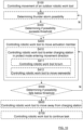
- a robotic work tool system comprising controlling the movement of an outdoor robotic work tool and controlling the outdoor robotic work tool to move an activation member at an outdoor robotic work tool charging station used for charging at least one rechargeable electric power source of the outdoor robotic work tool.
- the movement is made in an activation direction such that an electrical switch arrangement is activated and a protect mode is entered, wherein, upon activation, the electrical switch arrangement is used for isolating at least one electric unit from at least one electrical connection. Upon de-activation, the electrical switch arrangement is used for electrically connecting the electric unit to said electrical connection.
- the outdoor robotic work tool can activate and de-activate a switch arrangement that is adapted to break an electrical connection when activated, such that at least one electric is isolated from at least one electrical connection.
- This enables a possibility to protect electrical components both in the charging station and in the outdoor robotic work tool, where such a protection for example is desired in the case of a thunderstorm condition where electrical surges can occur due to lightning strikes.
- the charging station is adapted for a charging entering movement direction and a protect mode entering movement direction that differs from the charging entering movement direction.
- Controlling the outdoor robotic work tool to move an activation member comprises controlling the outdoor robotic work tool to enter the charging station in the protect mode entering movement direction.
- controlling the outdoor robotic work tool to enter the charging station in the protect mode entering movement direction comprises controlling the outdoor robotic work tool to be positioned away from the charging station with its back facing the activation member, and controlling the outdoor robotic work tool to move rearwards towards the activation member until the activation member is moved sufficiently to activate the electrical switch arrangement.
- the method comprises determining the possibility of the occurrence of a thunder storm by receiving weather data from a remote server.
- the method comprises determining if the possibility of the occurrence of a thunder storm exceeds a certain threshold, and if that is the case, the method comprises controlling the outdoor robotic work tool to move the activation member in the activation direction.
- the method comprises determining if the possibility of the occurrence of a thunder storm falls below a certain threshold. If that is the case, the method further comprises controlling the outdoor robotic work tool to move away from the charging station such that the activation member is released sufficiently, such that it is moved in a de-activation direction, to de-activate the electrical switch arrangement, and controlling the outdoor robotic work tool to continue its previously discontinued task.
- the present disclosure also relates to outdoor robotic work tool charging stations, outdoor robotic work tools and robotic work tool systems that are associated with the above advantages.
- FIG 1A shows a perspective view of a robotic lawn mower 100
- Figure 1B shows a schematic overview of the robotic lawn mower 100
- the robotic lawn mower 100 is adapted for a forward travelling direction D, has a main body 140 and a plurality of wheels 130; in this example the robotic lawn mower 100 has four wheels 130, two front wheels and two rear wheels.
- the robotic lawn mower 100 comprises a control unit 110 and at least one electric motor 150, where at least some of the wheels 130 are drivably connected to at least one electric motor 150. It should be noted that even if the description herein is focused on electric motors, combustion engines may alternatively be used in combination with an electric motor arrangement.
- the robotic lawn mower 100 may be a multi-chassis type or a mono-chassis type.
- a multi-chassis type comprises two or more body parts that are movable with respect to one another.
- a mono-chassis type comprises only one main body part.
- the robotic lawn mower 100 is of a mono-chassis type, having a main body part 140.
- the main body part 140 substantially houses all components of the robotic lawn mower 100.
- the robotic lawn mower 100 also comprises a grass cutting device 160, such as a rotating blade or a disc 160 with a plurality of separate rotating blades driven by a cutter motor 165.
- the robotic lawn mower 100 also has at least one rechargeable electric power source such as a battery 155 for providing power to the electric motor arrangement 150 and/or the cutter motor 165.
- the battery 155 is arranged to be charged by means of received charging current from a charging station (not shown), received through charging skids 156 or other suitable charging connectors, generally constituted by a charging reception arrangement 156. Inductive charging without galvanic contact, only by means of electric contact, is also conceivable.
- the battery is generally constituted by a rechargeable electric power source 155 that comprises one or more batteries that can be separately arranged or be arranged in an integrated manner to form a combined battery.
- the robotic lawn mower 100 may further comprise at least one navigation sensor arrangement 175 in a previously known manner, for example comprising a satellite navigation sensor in the form of a GPS (Global Positioning System) device or other Global Navigation Satellite System (GNSS) device, according to some aspects for example using Real Time Kinematic (RTK).
- a satellite navigation sensor in the form of a GPS (Global Positioning System) device or other Global Navigation Satellite System (GNSS) device, according to some aspects for example using Real Time Kinematic (RTK).
- GPS Global Positioning System
- GNSS Global Navigation Satellite System
- RTK Real Time Kinematic
- the robotic lawn mower 100 further comprises at least one environment detection device 170.
- radar transceivers 170 are provided and adapted to transmit signals and to receive reflected signals in a previously well-known manner.
- each radar transceiver 170 comprises a corresponding transmitter arrangement and receiver arrangement together with other necessary circuitry in a well-known manner.
- control unit 110 is adapted to control the environment detection device 170 and to control the speed and direction of the robotic lawn mower 100 in dependence of information acquired by means of the of the environment detection device 170 when the robotic lawn mower 100 is moving.
- control unit 110 is adapted to at least partly process input data from at least one environmental detection device 170.
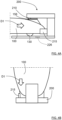
- the charging station 200 comprises a charging transmission arrangement 210 that is adapted to transfer a charging current to the charging reception arrangement 156.
- the charging station 200 comprises an electrical switch arrangement 216.
- the electrical switch arrangement 216 is adapted to isolate at least one electric unit 220, 221, 222, 223, 224 from at least one electrical connection 230, 231, 232, 233, 234 upon activation such that a protect mode is entered, and to electrically connect the electric unit 220, 221, 222, 223, 224 to said electrical connection 230, 231, 232, 233, 234 when de-activated.
- An activation member 215 is adapted to activate the electrical switch arrangement 216 when being moved in an activation direction A1, according to some aspects by being pushed, towards the charging station 200.
- the electrical switch arrangement 216 is adapted to be activated by the robotic lawn mower 100 when the robotic lawn mower 100 moves the activation member 215 sufficiently in the activation direction A1, and to be de-activated when the robotic lawn mower 100 moves or releases the activation member 215 such that it is moved sufficiently in a de-activation direction A2.
- the terms sufficiently relates to an extent that confers a mode change of the electrical switch arrangement 216, such that the electrical switch arrangement 216 switches from one switch state to another switch state.
- the activation member 215 being moved in the activation direction A1 corresponds to the robotic lawn mower 100 entering the charging station 200 in a protect mode entering movement direction D2
- the activation member 215 being moved in the de-activation direction A2 corresponds to the robotic lawn mower 100 leaving the charging station 200, according to some aspects in the opposite direction.
- the robotic lawn mower 100 can activate and de-activate the switch arrangement 216 that is adapted to break an electrical connection when activated, such that electrical components can be protected.
- a protection is for example desired in the case of a thunderstorm condition where electrical surges can occur due to lightning strikes.
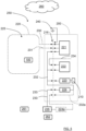
- FIG. 3 that illustrates a robotic work tool system 250 in a schematic manner
- a work area 225 that is enclosed by a boundary wire 220 with the purpose of keeping the robotic lawn mower 100 inside the work area 225.
- An electric control signal may be transmitted through the boundary wire 220 thereby generating a magnetic field emanating from the boundary wire 220.
- the robotic work tool system 250 comprises a boundary wire signal generator 221 that is connected to the boundary wire 220 and is adapted to handle all signaling to and from the boundary wire 220.
- the robotic lawn mower 100 comprises a boundary wire control signal sensor arrangement 228 that is adapted to detect boundary wire signals, where the boundary wire control signal sensor arrangement 228 comprises one or more sensor elements, where there for example can be a plurality of distributed sensor elements.
- Each electric unit as mentioned above can be constituted by one or more different types of units.
- the electric unit can be constituted by one of the boundary wire 220, the boundary wire signal generator 221, a charger control unit 222, a charging unit 223 and a power supply unit 224 that is connected to a mains power outlet 235.
- the boundary wire 220 can be disconnected from the boundary wire signal generator 221, thereby protecting the boundary wire signal generator 221 in case a lightning strike causes an electrical surge in the boundary wire 220.
- One or more of the above electric units can be disconnected and isolated by means of the electrical switch arrangement 216 as described above. If, for example, the power supply unit 224 is not comprised in the charging station 200 but is constituted by a separate external unit that is remote from the charging station 200, the power supply unit 224 may not be possible to isolate from the mains power outlet 235 by means of the electrical switch arrangement 216. This is illustrated by an alternative power supply unit 224a, indicated by dashed lines, where the alternative power supply unit 224a is an external power supply unit 224a that can be an indoor unit or placed remote from the charging station 200 in some other manner, for example connected to an outdoor mains power outlet.
- the robotic work tool system 250 being arranged without a boundary wire and solely depending on a navigation sensor arrangement 175 as described above, there is of course no need to isolate a boundary wire 220 and boundary wire signal generator 221 since these in that case are not comprised in the robotic work tool system 250.
- the robotic work tool system 250 may be arranged for a navigation sensor arrangement 175 together with a relatively small boundary wire at the charging station, only be being used to aid the lawn mower 100 when docking to the charging station 200,
- Which electric units that are adapted to be disconnected and isolated by means of the electrical switch arrangement 216 is thus dependent on which electric units that are comprised in the robotic work tool system 250 and are accessible for the electrical switch arrangement 216, as well as on which electric units that are considered necessary or desired to protect from electrical surges of the kind described above. Practical aspects and cost aspects are also important when determining which electric units that are adapted to be disconnected and isolated by means of the electrical switch arrangement 216.
- the electrical switch arrangement 216 is adapted to provide a mechanical separation S1, S2, constituting an isolation distance, between adjacent electrical conductors C1, C2 of at least 5 cm when activated, and preferably at least 10 cm.
- the electrical switch arrangement 216 is schematically indicated as de-activated, closing a connection between the two adjacent electrical conductors C1, C2.
- These electrical conductors C1, C2 are indicated in a general manner and can connect any electric unit, for example one of the electrical conductors C1 can be an electrical connector leading to the boundary wire 220 and the other electrical conductor C2 can be a connection to the boundary wire signal generator 221.
- the activation member 215 is connected to the electrical switch arrangement 216 either directly or via a mechanical linkage (not shown).
- a mechanical linkage can be adapted to make it easier to accomplish a sufficient isolation distance.
- the electrical connection 230, 231, 232, 233, 234 is constituted by at least one of a boundary wire connection 230, 231, a power supply connection 232, a mains power connection 233 and a data signal bus 234.
- the power supply unit 224a being external power supply unit 224a
- Each electrical connection normally comprises one or more electrical wires, for example a signal wire and a ground wire such as a live wire and a neutral wire, for example wires with different AC or DC voltages.
- a signal wire and a ground wire such as a live wire and a neutral wire, for example wires with different AC or DC voltages.
- a neutral wire for example wires with different AC or DC voltages.
- an electric connection that is isolated from the boundary wire 220 is a boundary wire connection 230, 231
- an electric connection that is isolated from the boundary wire signal generator 221 is a charger control unit 222 and/or the charger unit 223
- an electric connection that is isolated from the power supply unit 224 is a mains power connection 233.
- an electric connection that is isolated from the charger control unit 222 is a data signal bus 234.
- the data signal bus 234 can be arranged for input of data signals to the charger control unit 222, output of data signals from the charger control unit 222, or both.
- an example of a typical configuration can be a robotic work tool system with an external power supply unit 224a, and when the electrical switch arrangement 216 is activated, the boundary wire 220 is isolated from the boundary wire connection 230, 231 and the boundary wire signal generator 221, the charger control unit 222 and/or the charger unit 223 are isolated from the power supply connection 232a. In this case, no other electrical units are isolated when the electrical switch arrangement 216 is activated.
- the charging station 200 is not in operation, needing external input to be reinstated into operation.
- This external input is according to some aspects, provided by means of the robotic lawn mower 100 that still is operational by means of its battery power as will be described below.
- the charging transmission arrangement 210 of the charging station 200 is not engaged when the electrical switch arrangement 216 is activated.
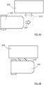
- the electrical switch arrangement 216 is to be de-activated, the robotic lawn mower 100 is controlled to move away from the charging station 200 and to either move away to continue an interrupted task such as grass mowing, or to turn around and engage the charging station 200 such that the charging reception arrangement 156 can make electrical contact with the charging transmission arrangement 210 as illustrated in Figure 4A and Figure 4B .
- the robotic lawn mower 100 is charging, the activation member 215 is not engaged, and the electrical switch arrangement 216 is de-activated as illustrated in Figure 5 .
- the robotic lawn mower 100 then enters the charging station 200 in a charging entering movement direction D1 and initiates a charging mode. In this case, the activation member 215 is not engaged by means of exterior design of the robotic lawn mower 100.
- a magnet 226 positioned in the charging station 200, where the magnet 226 is detectable by a magnet field detector 227 comprised in the robotic lawn mower 100 when the robotic lawn mower 100 is positioned such that the switch arrangement 216 is activated.
- the purpose of this arrangement is that the control unit 110 of the robotic lawn mower 100 can determine its position more easily when the switch arrangement 216 is to be de-activated by the robotic lawn mower 100 moving away from the charging station 200. For example, the control unit 110 can then determine whether the robotic lawn mower 100 has been moved.
- control unit 110 can determine that the robotic lawn mower 100 is in a correct position when the switch arrangement 216 is to be de-activated, the control unit 110 can control the robotic lawn mower 100 to move away from the charging station 200 such that the activation member 215 is released and the boundary wire signal generator 221 re-connected to the boundary wire 220 and to the power supply unit 224 such that the control unit 110 can determine the position of the robotic lawn mower 100 by means of the boundary wire 220.
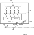
- FIG. 8A, 8B and 8C show a robotic lawn mower 100 that docks the charging station 200' for charging
- Figure 9A, 9B and 9C show a robotic lawn mower 100 that docks the charging station 200' for entering a protect mode.
- the robotic lawn mower 100 approaches and enters the charging station 200' in a charging entering movement direction D1' and electrical contact is made with a charging transmission arrangement 210'.
- the charging transmission arrangement 210' is in the form of rods or similar that extend out from a side of the charging station 200' that is in the form of a drive-thru charging station 200'.
- the charging transmission arrangement 210' is bent in the charging entering movement direction D1'.
- the charging transmission arrangement 210' comprises a first charging member 210'a and a second charging member 210'b and an electrical switch arrangement 216, where the charging members 210'a 210'b make contact with a charging reception arrangement 156'.
- the electrical switch arrangement 216 being deactivated means that a power supply connection 232 and a boundary wire connection 230, 231 are connected to associated components 800, where the associated components 800 for example comprises one or more electrical units such as for example a boundary wire signal generator, a charger control unit and a charging unit as described previously.
- the robotic lawn mower 100 approaches and enters the charging station 200' in a protect mode entering movement direction D2' and electrical contact is in this case not made with charging transmission arrangement 210' since the charging reception arrangement 156' is not accessible for the charging transmission arrangement 210'.
- the charging transmission arrangement 210' is bent in the protect mode entering movement direction D2' which corresponds to an activation direction A1'.
- the charging station 200' is shown with the docked robotic lawn mower 100 in a protect mode.
- the electrical switch arrangement 216 is thus activated, which means that the power supply connection 232 and the boundary wire connection 230, 231 are isolated from the associated components 800.
- the electrical switch arrangement 216 is activated by means of the second charging member 210'b being moved in an activation direction A1', where the second charging member 210'b comprises a switch activation part 801 that is adapted to activate the electrical switch arrangement 216.
- the activation member is comprised in the charging transmission arrangement 210'.
- the charging transmission arrangement 210' comprises a first charging member 210'a and a second charging member 210'b, where the electrical switch arrangement 216' is adapted to be activated by means of the second charging member 210'b, constituting the activation member, being moved in the activation direction A1'.
- the second charging member 210'b comprises a switch activation part 801 that is adapted to activate the electrical switch arrangement 216.
- the illustrated example corresponds to a typical configuration with an external power supply unit 224a, and when the electrical switch arrangement 216' is activated, a boundary wire is isolated from the boundary wire connection 230, 231 and the associated components 800 are isolated from the power supply connection 232.
- Other combinations of electrical units that are isolated when the electrical switch arrangement 216' is activated are of course conceivable as discussed previously for the first example.
- the second charging member 210'b also constitutes an activation member in accordance with the previous examples.
- an activation member there may of course be a separate activation member, it is not necessary to use a charging member.
- Such a separate activation member can be positioned a certain height.
- the activation member may have any suitable position such as under the robotic lawn mower 100 or above the robotic lawn mower 100 when docked.
- the activation member 210'b being moved in the activation direction A1' corresponds to the robotic lawn mower 100 entering the charging station 200' in the protect mode entering movement direction D2'
- the activation member 210'b being moved in a de-activation direction A2' corresponds to the robotic lawn mower 100 leaving the charging station 200' in the same direction.
- the present disclosure relates to a method for a robotic work tool system 250, which method is described in the following with reference to Figure 10 .
- the method comprises controlling S100 the movement of an outdoor robotic work tool such as a robotic lawn mower 100 and controlling S400 the robotic lawn mower 100 to move an activation member 215 at a charging station 200 used for charging a at least one rechargeable electric power source 155 of the robotic lawn mower 100, where the movement is made in an activation direction A1 such that an electrical switch arrangement 216 is activated and a protect mode is entered.
- the electrical switch arrangement 216 Upon activation, the electrical switch arrangement 216 is used for isolating at least one electric unit 220, 221, 222, 223, 224 from at least one electrical connection 230, 231, 232, 233, 234, and upon de-activation the electrical switch arrangement 216 is used for electrically connecting the electric unit 220, 221, 222, 223, 224 to said electrical connection 230, 231, 232, 233, 234.
- the robotic lawn mower 100 can activate and de-activate a switch arrangement 216 that is adapted to break an electrical connection when activated, such that at least one electric unit 220, 221, 222, 223, 224 is isolated from at least one electrical connection 230, 231, 232, 233, 234.
- a switch arrangement 216 that is adapted to break an electrical connection when activated, such that at least one electric unit 220, 221, 222, 223, 224 is isolated from at least one electrical connection 230, 231, 232, 233, 234.
- the charging station 200 is adapted for a charging entering movement direction D1, D1' and a protect mode entering movement direction D2, D2' that differs from the charging entering movement direction D1, D1'.
- Controlling S400 the robotic lawn mower 100 to move an activation member comprises controlling S410 the robotic lawn mower 100 to enter the charging station 200 in the protect mode entering movement direction D2, D2'.
- the charging entering movement direction D1 can relate to entering the charging station 200 in a forward movement direction as illustrated in Figure 4A and Figure 4B
- the protect mode entering movement direction D2 can relate to entering the charging station 200 in a rearward movement direction as illustrated in Figure 2A and Figure 2B
- the charging entering movement direction D1' can relate to the robotic lawn mower 100 entering the charging station 200 in a forward movement direction as illustrated in Figure 8A
- the protect mode entering movement direction D2' can relate to the robotic lawn mower 100 entering the charging station 200 in the forward movement direction but incoming from another direction as illustrated in Figure 9A .
- controlling S410 the robotic lawn mower 100 to enter the charging station 200 in the protect mode entering movement direction D2, D2' comprises controlling S411 the robotic lawn mower 100 to be positioned away from the charging station 200 with its back facing the activation member 215, and controlling S412 the robotic lawn mower 100 to move rearwards towards the activation member 215 until the activation member 215 is moved sufficiently to activate the electrical switch arrangement 216.
- the robotic lawn mower 100 is controlled to move away from the charging station 200 and to turn such that its back is facing the activation member 215, and then to move rearwards towards the activation member 215.
- the method comprises determining S300 if the possibility of the occurrence of a thunder storm exceeds a certain threshold. If that is the case, the method further comprises controlling S400 the robotic lawn mower 100 to move the activation member 215 in the activation direction. Alternatively, controlling S400 the robotic lawn mower 100 to press the activation member 215 can be initiated by a user that wants the robotic work tool system 250 to enter a protect mode where the electrical switch arrangement 216 is activated. This can for example be performed by means of a mobile phone application program (App) or a remote control. Both alternatives are of course conceivable for the same robotic work tool system 250.
- App mobile phone application program
- the method comprises determining 200 the possibility of the occurrence of a thunder storm by receiving weather data from a remote server 260.
- the remote server 260 is adapted to collect weather data, for example from an Internet weather service.
- the weather data can according to some aspects be acquired from the remote server 260 by the charger control unit 222, a mobile phone App at a user terminal 261 or a local server 262.
- the lawn mower 100 and its control unit 110 can be instructed by the charger control unit 222, a mobile phone App, a remote server 260 and/or a local server 262.
- a combination is of course possible, for example where an App runs via a remote server, or when the lawn mower 100 and its control unit 110 can be instructed by several units such as both a remote server 260 and an App.
- the App can be manually operated by a user that for example hears distant thunder approaching.
- Communication between the lawn mower 100 with its control unit 110 and other units such as the charger control unit 222, a mobile phone App, a remote server 260 and/or a local server 262 can for example be made via a cell phone communication network, WiFi and/or Bluetooth.
- the lawn mower 100 may be adapted for direct access to a cell phone communication network.
- the method comprises determining S500 if the possibility of the occurrence of a thunder storm falls below a certain threshold. If that is the case, the method further comprises controlling S600 the robotic lawn mower 100 to move away from the charging station 200 such that the activation member 215 is released sufficiently, such that it is moved in a de-activation direction, to de-activate the electrical switch arrangement 216, and controlling S700 the robotic lawn mower 100 to continue its previously discontinued task.
- the robotic lawn mower 100 In case the robotic lawn mower 100 previously was charging, the robotic lawn mower 100 is controlled to move to such a position at the charging station that the robotic lawn mower 100 can continue charging the rechargeable electric power source 155 by receiving a charging current from the charging station 200. Otherwise, the robotic lawn mower 100 is controlled to continue its previously discontinued task, for example continue mowing grass or continue to move to a desired position.
- controlling the robotic lawn mower 100 to move away from the charging station 200 such that the activation member 215 is released sufficiently to de-activate the electrical switch arrangement 216 can also be performed after the lapse of a predetermined time period.
- the present disclosure also relates to an robotic lawn mower 100 adapted for a forward travelling direction D and comprising a control unit 110, a charging reception arrangement 156 adapted for making electrical contact with a charging transmission arrangement 210 of a robotic lawn mower charging station 200, and at least one environmental detector device 170.
- the control unit 110 is adapted to control the movement of the robotic lawn mower 100 in dependence of information acquired by means of the environmental detector device 170.
- the control unit 110 is further adapted to control the robotic work tool 100 to move an activation member 215 at the charging station when the control unit 110 has received corresponding instructions, where the movement is made in an activation direction such that an electrical switch arrangement 216 is activated and a protect mode is entered.
- control unit 110 is adapted to receive instructions from at least one of a charger control unit 222, a mobile phone application program App running at a user terminal 261, a remote server 260 or local server 262.
- the corresponding instructions relate to a possibility of the occurrence of a thunder storm.
- the corresponding instructions relate to user input via a user terminal 261.
- control unit 110 is adapted to control the robotic work tool 100 to move to the charging station 200 in a protect mode entering movement direction D2, D2' that differs from a charging entering movement direction D1, D1', and to move the activation member 215 in the activation direction A1 when the control unit 110 has received corresponding instructions.
- the robotic work tool 100 is adapted to move or release the activation member 215 such that it is moved sufficiently in a de-activation direction A2 when the control unit 110 has received corresponding instructions, such that the electrical switch arrangement 216 is de-activated and the protect mode is left.
- the environmental detector device 170 can comprise at least one of a radar transceiver, Lidar transceiver, ultrasonic transceiver and/or a camera device.
- the robotic lawn mower is an outdoor robotic work tool 100 and the robotic lawn mower charging station is an outdoor robotic work tool charging station 200.
- the charging station can be constituted by an outdoor robotic work tool interaction station 200. Except charging, such an interaction station can be constituted by a maintenance stations such as a knife sharping station, or a dumping station. The latter can for example be the case when the outdoor robotic work tool can be adapted to collect items such as leafs or golf balls. Another example of an interaction station is a marker of a lawn mower off-limit area such as an area around a plant that should be left.
- Figure 7 shows a computer program product 500 comprising computer executable instructions 510 stored on media 520 to execute any of the methods disclosed herein.
- the computer program product 500 can be solely or at least partly implemented for at least one of a charger control unit 222, a user terminal 261, a remote server 260 and/or a local server 262.
- a local server 262 can for example be constituted by an indoor user computer unit.
- the outdoor robotic work tool interaction station 200 is an outdoor robotic work tool charging station, where the control unit 110 of the robotic lawn mower 100 is adapted to control the movement of the robotic lawn mower 100 such that it moves to such a position at the outdoor robotic work tool charging station 200 such that the charging reception arrangement 156 can make electrical contact with the charging transmission arrangement 210.
- the robotic lawn mower 100 can then receive a charging current from the outdoor robotic work tool charging station 200.
- the present disclosure also relates to a robotic work tool system 250 comprising the outdoor robotic work tool charging station 200 and the outdoor robotic work tool 100 according the above.
- the robotic work tool system 250 further comprises said electric unit 220, 221, 222, 223, 224 that is adapted to be isolated from at least one electrical connection 230, 231, 232, 233, 234 upon activation of the electrical switch arrangement 216.
- the robotic work tool system 250 further comprises at least one of a remote server 260, a user terminal 261, or a local server 262, where the control unit 110 of the outdoor robotic work tool 100 is adapted to receive instructions from at least one of the charger control unit 222, the mobile phone application program (App) running at the user terminal 261, the remote server 260 or the local server 262.
- App mobile phone application program
- the electrical switch arrangement 216 upon activation, is adapted to connect at least one electrical connection 230 to a ground connection 240.
- a ground connection 240 This provides a further protection, since one or more electric units can be securely grounded.
- the boundary wire 220 can be switched to be directly connected to ground instead of being connected to the boundary wire signal generator 221.
- the ground connection 240 comprises a metal rod that is inserted into the ground.
- the electrical switch arrangement 216 can be realized in many different ways, as evident to the skilled person.
- the electrical switch arrangement 216 may comprise different types of individual switches depending on if a certain switch is adapted to open and close a low-power connection, a high power connection or a data signal connection.
- the activation member 215 can be biased by a resilient member, such as a spring, that urges the activation member 215 in the de-activation direction A2. Then the activation member 215 moves in the de-activation direction A2 when being released by the robotic lawn mower, otherwise the activation member 215 is moved in the de-activation direction A2 by the robotic lawn mower.
- a resilient member such as a spring
- the activation member 215 can be formed in many ways.
- the activation member 215 is shown as protruding a protruding member, but it can also be formed to be flush with, or as an indent in, a surface of the charging station 200.
- the activation member 215 is accessible by the robotic lawn mower 100 when approaching the charging station 200 in the protect mode entering movement direction D2.
- the activation member 215 has been described to be mechanically operated in different ways, but other alternatives are of course conceivable.
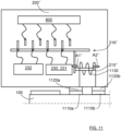
- the robotic lawn mower 100 is adapted to move an activation member 215" electromechanically, where lawn mower electric contact members 1110a, 1110b, for example constituted by charging skids or by separate contact members comprised in the robotic lawn mower 100, are adapted to contact charging station contact members 1120a, 1120b, for example constituted by a charging transmission arrangement or by separate contact members, when the protect mode is about to be entered.
- the robotic lawn mower 100 is adapted to transmit a first electric current to a solenoid arrangement 1130 in the charging station 200" via the electric contact members 1110a, 1110b; 1120a, 1120b such that the activation member 215" is moved in the activation direction A1" by the solenoid arrangement 1130.
- the robotic lawn mower 100 is adapted to transmit a second electric current to the solenoid arrangement 1130 in the charging station 200" via the electric contact members 1110a, 1110b; 1120a, 1120b such that the activation member 215" is moved in the de-activation direction A2" by the solenoid arrangement 1130.
- the activation member 215" is an internal component of the charging station 200", not being physically accessible from the outside, being movable by means of the solenoid arrangement 1130".
- the protect mode can be entered directly from a charging mode.
- the robotic lawn mower 100 then communicates with the charging station control unit 222, ordering the charging station's control unit 222 to discontinue the charging mode and connect the charging station contact members 1120a, 1120b to the solenoid arrangement 1130. This can be accomplished by means of an electrically controllable switch comprised in the charging station.
- the charging station 200" comprises charging station contact members 1120a, 1120b that are adapted to contact robotic work tool electric contact members 1110a, 1110b comprised in an outdoor robotic work tool 100, when the protect mode is about to be entered, where the charging station 200" is adapted to receive a first electric current to a solenoid arrangement 1130 comprised in the charging station 200" via the electric contact members 1110a, 1110b; 1120a, 1120b such that the activation member 215" is moved in the activation direction A1" by the solenoid arrangement 1130, where furthermore the charging station 200" is adapted to receive a second electric current to the solenoid arrangement 1130 via the electric contact members 1110a, 1110b; 1120a, 1120b such that the activation member 215" is moved in the de-activation direction A2" by the solenoid arrangement 1130 such that the protect mode is left.
- This external input is according to some aspects, provided by means of the robotic lawn mower 100 that still is operational by means of its battery power.
Landscapes
- Engineering & Computer Science (AREA)
- Life Sciences & Earth Sciences (AREA)
- Environmental Sciences (AREA)
- Power Engineering (AREA)
- Transportation (AREA)
- Mechanical Engineering (AREA)
- Charge And Discharge Circuits For Batteries Or The Like (AREA)
- Harvester Elements (AREA)
Claims (15)
- Verfahren für ein Roboterarbeitswerkzeugsystem (250), wo das Verfahren Folgendes umfasst:Steuern (S100) der Bewegung eines Roboterarbeitswerkzeugs (100) für Außenbereiche;gekennzeichnet durchSteuern (S400) des Roboterarbeitswerkzeugs (100) für Außenbereiche zum Bewegen eines Aktivierungselements (215) an einer Roboterarbeitswerkzeugladestation (200) für Außenbereiche, die zum Laden von mindestens einer ladbaren elektrischen Stromquelle (155) des Roboterarbeitswerkzeugs (100) für Außenbereiche verwendet wird, wo das Aktivierungselement (215) in eine Aktivierungsrichtung (A1) bewegt wird, derart, dass eine elektrische Schalteranordnung (216) aktiviert und in einen Schutzmodus eingetreten wird, wobei nach Aktivierung der elektrischen Schalteranordnung (216) die elektrische Schalteranordnung (216) zum Trennen von mindestens einer elektrischen Einheit (220, 221, 222, 223, 224) von mindestens einer elektrischen Verbindung (230, 231, 232, 233, 234) verwendet wird und nach die Aktivierung der elektrischen Schalteranordnung (216) der Schutzmodus verlassen wird und die elektrische Schalteranordnung (216) zum elektrischen Verbinden der elektrischen Einheit (220, 221, 222, 223, 224) mit der elektrischen Verbindung (230, 231, 232, 233, 234) verwendet wird.
- Verfahren nach Anspruch 1, wobei die Ladestation (200) für eine Ladungseintrittsbewegungsrichtung (D1, D1') und eine Schutzmoduseintrittsbewegungsrichtung (D2, D2'), die sich von der Ladungseintrittsbewegungsrichtung (D1, D1') unterscheidet, angepasst ist, wo das Steuern (S400) des Roboterarbeitswerkzeugs (100) für Außenbereiche zum Bewegen eines Aktivierungselements das Steuern (S410) des Roboterarbeitswerkzeugs (100) für Außenbereiche zum Eintreten in der Schutzmoduseintrittsbewegungsrichtung (D2, D2') in die Ladestation (200) umfasst.
- Verfahren nach Anspruch 2, wobei das Steuern (S410) des Roboterarbeitswerkzeugs (100) für Außenbereiche zum Eintreten in der Schutzmoduseintrittsbewegungsrichtung (D2, D2') in die Ladestation (200) Folgendes umfasst:Steuern (S411) des Roboterarbeitswerkzeugs (100) für Außenbereiche zum Positionieren von der Ladestation (200) weg, wobei seine Rückseite dem Aktivierungselement (215) zugewandt ist; undSteuern (S412) des Roboterarbeitswerkzeugs (100) für Außenbereiche zum Rückwärtsbewegen des Aktivierungselements (215), bis das Aktivierungselement (215) zum Aktivieren der elektrischen Schalteranordnung (216) ausreichend bewegt ist.
- Verfahren nach einem der vorhergehenden Ansprüche, wobei das Verfahren Folgendes umfasst:
Bestimmen (S300), ob die Möglichkeit des Auftretens eines Gewitters einen gewissen Schwellwert überschreitet, und wenn dies der Fall ist, umfasst das Verfahren das Steuern (S400) des Roboterarbeitswerkzeugs (100) für Außenbereiche zum Bewegen des Aktivierungselements (215) in die Aktivierungsrichtung. - Verfahren nach einem der vorhergehenden Ansprüche, wobei das Verfahren Folgendes umfasst:
Bestimmen (S500), ob die Möglichkeit des Auftretens eines Gewitters unter einem gewissen Schwellwert liegt, und wenn dies der Fall ist, umfasst das Verfahren ferner Folgendes:Steuern (S600) des Roboterarbeitswerkzeugs (100) für Außenbereiche zum Wegbewegen von der Ladestation (200), derart, dass das Aktivierungselement (215) ausreichend gelöst wird, derart, dass es in eine Deaktivierungsrichtung bewegt wird, um die elektrische Schalteranordnung (216) zu deaktivieren; undSteuern (S700) des Roboterarbeitswerkzeugs (100) für Außenbereiche zum Fortsetzen seiner vorhergehenden unterbrochenen Aufgabe. - Roboterarbeitswerkzeugladestation (200) für Außenbereiche, die eine Ladungsübertragungsanordnung (210) umfasst
gekennzeichnet durch
eine elektrische Schalteranordnung (216), die nach Aktivierung zum Trennen von mindestens einer elektrischen Einheit (220, 221, 222, 223, 224) von mindestens einer elektrischen Verbindung (230, 231, 232, 233, 234), derart, dass in einen Schutzmodus eingetreten wird, und zum elektrischen Verbinden der elektrischen Einheit (220, 221, 222, 223, 224) mit der elektrischen Verbindung (230, 231, 232, 233, 234), wenn sie deaktiviert wird, angepasst ist, wo die elektrische Schalteranordnung (216) ein Aktivierungselement (215) umfasst, das zum Aktivieren der elektrischen Schalteranordnung (216) angepasst ist, wenn es in eine Aktivierungsrichtung (A1) bewegt wird, wobei die elektrische Schalteranordnung (216) angepasst ist, von einem Roboterarbeitswerkzeug (100) für Außenbereiche aktiviert zu werden, wenn das Roboterarbeitswerkzeug (100) das Aktivierungselement (215) ausreichend in die Aktivierungsrichtung (A1) bewegt, und deaktiviert zu werden, wenn das Roboterarbeitswerkzeug (100) das Aktivierungselement (215) bewegt oder löst, derart, dass es ausreichend in eine Deaktivierungsrichtung (A2) bewegt wird. - Ladestation (200) nach Anspruch 6, wobei die elektrische Einheit durch eines von einem Begrenzungsdraht (220), einem Begrenzungsdrahtsignalgenerator (221), einer Ladegerätsteuereinheit (222), einer Ladeeinheit (223) und einer Stromversorgungseinheit (224) konstituiert wird.
- Ladestation (200) nach einem der Ansprüche 6 oder 7, wobei die elektrische Verbindung (230, 231, 232, 233, 234) durch mindestens eines einer Begrenzungsdrahtverbindung (230, 231), einer Stromversorgungsverbindung (232), einer Netzstromverbindung (233) und einem Datensignalbus (234) konstituiert wird.
- Roboterarbeitswerkzeug (100) für Außenbereiche, das für eine Vorwärtsfahrtrichtung (D) angepasst ist und eine Steuereinheit (110), eine Ladungsempfangsanordnung (156), die zum Herstellen eines elektrischen Kontakts mit einer Ladungsübertragungsanordnung (210) einer Roboterarbeitswerkzeugladestation (200) für Außenbereiche angepasst ist, und mindestens eine Umgebungsdetektorvorrichtung umfasst, wo die Steuereinheit (110) zum Steuern der Bewegung des Roboterarbeitswerkzeugs (100) für Außenbereiche in Abhängigkeit von Informationen angepasst ist, die mittels der Umgebungsdetektorvorrichtung erfasst werden, dadurch gekennzeichnet, dass
die Steuereinheit (110) zum Steuern des Roboterarbeitswerkzeugs (100) angepasst ist, um ein Aktivierungselement (215) an der Ladestation zu bewegen, wenn die Steuereinheit (110) entsprechende Anweisungen empfangen hat, wo das Aktivierungselement (215) in eine Aktivierungsrichtung (A1) bewegt wird, derart, dass eine elektrische Schalteranordnung (216) aktiviert und in einen Schutzmodus eingetreten wird. - Roboterarbeitswerkzeug (100) für Außenbereiche nach Anspruch 9, wobei die Steuereinheit (110) zum Empfangen von Anweisungen von mindestens einem von einer Ladegerätsteuereinheit (222), einem Mobiltelefonanwendungsprogramm (App), das auf einem Benutzerendgerät (261) läuft, einem entfernten Server (260) oder einem lokalen Server (262) angepasst ist.
- Roboterarbeitswerkzeug (100) für Außenbereiche nach einem der Ansprüche 9 oder 10, wobei die entsprechenden Anweisungen eine Möglichkeit des Auftretens eines Gewitters betreffen.
- Roboterarbeitswerkzeug (100) für Außenbereiche nach einem der Ansprüche 9-11, wobei die entsprechenden Anweisungen eine Benutzereingabe via ein Benutzerendgerät (261) betreffen.
- Roboterarbeitswerkzeug (100) für Außenbereiche nach einem der Ansprüche 9-12, wobei die Steuereinheit (110) zum Steuern des Roboterarbeitswerkzeugs (100) angepasst ist, um sich in einer Schutzmoduseintrittsbewegungsrichtung (D2, D2'), die sich von einer Ladungseintrittsbewegungsrichtung (D1, D1') unterscheidet, zur Ladestation (200) zu bewegen und das Aktivierungselement (215) in die Aktivierungsrichtung (A1) zu bewegen, wenn die Steuereinheit (110) entsprechende Anweisungen empfangen hat.
- Roboterarbeitswerkzeugsystem (250), das die Roboterarbeitswerkzeugladestation (200) nach einem der Ansprüche 6-8 und das Roboterarbeitswerkzeug (100) für Außenbereiche nach einem der Ansprüche 9-13 umfasst, wobei das Roboterarbeitswerkzeugsystem (250) ferner die elektrische Einheit (220, 221, 222, 223, 224) umfasst, die zum Getrenntwerden von mindestens einer elektrischen Verbindung (230, 231, 232, 233, 234) nach Aktivierung der elektrischen Schalteranordnung (216) angepasst ist.
- Roboterarbeitswerkzeugsystem (250) nach Anspruch 14, das ferner mindestens eines von einem entfernten Server (260), einem Benutzerendgerät (261) oder einem lokalen Server (262) umfasst, wo die Steuereinheit (110) des Roboterarbeitswerkzeugs (100) für Außenbereiche zum Empfangen von Anweisungen von mindestens einem der Ladegerätsteuereinheit (222) des Mobiltelefonanwendungsprogramms (App), das auf dem Benutzerendgerät (261) läuft, des entfernten Servers (260) oder des lokalen Servers (262) angepasst ist.
Applications Claiming Priority (1)
| Application Number | Priority Date | Filing Date | Title |
|---|---|---|---|
| SE2150067A SE544278C2 (en) | 2021-01-22 | 2021-01-22 | Electrical surge protection for an outdoor robotic work tool system |
Publications (2)
| Publication Number | Publication Date |
|---|---|
| EP4032385A1 EP4032385A1 (de) | 2022-07-27 |
| EP4032385B1 true EP4032385B1 (de) | 2024-05-22 |
Family
ID=79730534
Family Applications (1)
| Application Number | Title | Priority Date | Filing Date |
|---|---|---|---|
| EP22152149.5A Active EP4032385B1 (de) | 2021-01-22 | 2022-01-19 | Elektrischer überspannungsschutz für ein roboterwerkzeugsystem für den aussenbereich |
Country Status (2)
| Country | Link |
|---|---|
| EP (1) | EP4032385B1 (de) |
| SE (1) | SE544278C2 (de) |
Family Cites Families (6)
| Publication number | Priority date | Publication date | Assignee | Title |
|---|---|---|---|---|
| US8044810B2 (en) * | 2008-10-06 | 2011-10-25 | International Business Machines Corporation | System and method of damage prevention from weather occurrences |
| SE538776C2 (en) * | 2014-12-23 | 2016-11-15 | Husqvarna Ab | Improved operation of a robotic work tool by determining weather conditions and adapting the operation |
| SE539127C2 (en) * | 2015-08-20 | 2017-04-11 | Anders Karlzon Med Firma Zitt Innovation | A surge arrester for a domestic robot assembly |
| DE102015121972A1 (de) * | 2015-12-16 | 2017-06-22 | Vorwerk & Co. Interholding Gmbh | System und Verfahren zur Bearbeitung eines Bodens mit einer mobilen Robotereinheit |
| JP2020156289A (ja) * | 2019-03-22 | 2020-09-24 | 本田技研工業株式会社 | 充電制御システム、充電ステーション、自律走行作業機、及び充電制御システムの制御方法 |
| CN111452665B (zh) * | 2020-05-25 | 2021-09-24 | 南京能瑞电力科技有限公司 | 一种电动自行车智能充换电柜 |
-
2021
- 2021-01-22 SE SE2150067A patent/SE544278C2/en not_active IP Right Cessation
-
2022
- 2022-01-19 EP EP22152149.5A patent/EP4032385B1/de active Active
Also Published As
| Publication number | Publication date |
|---|---|
| SE2150067A1 (en) | 2022-03-22 |
| SE544278C2 (en) | 2022-03-22 |
| EP4032385A1 (de) | 2022-07-27 |
Similar Documents
| Publication | Publication Date | Title |
|---|---|---|
| EP3236734B1 (de) | Verbesserter betrieb eines robotischen arbeitswerkzeugs durch anpassung des betriebs an die wetterbedingungen | |
| EP3909412A1 (de) | Werkzeugroboter für den aussenbereich mit einem umwelterkennungssystem | |
| CN102811604B (zh) | 用于将机器人园林工具引导至预定位置的方法和系统 | |
| CN212278869U (zh) | 自移动设备及智能割草机 | |
| EP4118509B1 (de) | System und verfahren zur verbesserten navigation eines roboterarbeitswerkzeugs | |
| US7496459B2 (en) | Intelligent, self-propelled automatic grid crawler high impedance fault detector and high impedance fault detecting system | |
| EP4150425B1 (de) | Mobiler signalgenerator für ein robotisches arbeitswerkzeug | |
| EP2375301A2 (de) | Roboterelement und Lade- und Steuerungssystem dafür | |
| WO2021139685A1 (zh) | 一种自动工作系统 | |
| EP4000367B1 (de) | Energieeffizienter robotischer rasenmäher | |
| CN118348982A (zh) | 一种自移动设备 | |
| EP4032385B1 (de) | Elektrischer überspannungsschutz für ein roboterwerkzeugsystem für den aussenbereich | |
| SE2150683A1 (en) | A robotic lawn mower with enhanced cutting properties | |
| WO2023195885A1 (en) | A robotic lawn mower | |
| WO2022177486A1 (en) | Robotic work tool assistance in a robotic work tool system | |
| WO2023146451A1 (en) | Improved operation for a robotic work tool system | |
| US20230176584A1 (en) | Guidance for an outdoor robotic work tool to an outdoor robotic work tool interaction station | |
| EP4596304A2 (de) | Mittel und verfahren zur verbesserten robotischen arbeitswerkzeugaufladung | |
| US12468301B2 (en) | Working robot system | |
| SE2350661A1 (en) | Efficient charging of an outdoor robotic work tool | |
| EP4656027A1 (de) | Garage mit öffnungsfähigem deckel für robotischen rasenmäher | |
| SE2350591A1 (en) | Efficient charging of an outdoor robotic work tool | |
| US20230086392A1 (en) | Navigation for a robotic work tool system |
Legal Events
| Date | Code | Title | Description |
|---|---|---|---|
| PUAI | Public reference made under article 153(3) epc to a published international application that has entered the european phase |
Free format text: ORIGINAL CODE: 0009012 |
|
| STAA | Information on the status of an ep patent application or granted ep patent |
Free format text: STATUS: REQUEST FOR EXAMINATION WAS MADE |
|
| 17P | Request for examination filed |
Effective date: 20220119 |
|
| AK | Designated contracting states |
Kind code of ref document: A1 Designated state(s): AL AT BE BG CH CY CZ DE DK EE ES FI FR GB GR HR HU IE IS IT LI LT LU LV MC MK MT NL NO PL PT RO RS SE SI SK SM TR |
|
| GRAP | Despatch of communication of intention to grant a patent |
Free format text: ORIGINAL CODE: EPIDOSNIGR1 |
|
| STAA | Information on the status of an ep patent application or granted ep patent |
Free format text: STATUS: GRANT OF PATENT IS INTENDED |
|
| RIC1 | Information provided on ipc code assigned before grant |
Ipc: A01D 34/00 20060101AFI20240222BHEP |
|
| INTG | Intention to grant announced |
Effective date: 20240314 |
|
| GRAS | Grant fee paid |
Free format text: ORIGINAL CODE: EPIDOSNIGR3 |
|
| GRAA | (expected) grant |
Free format text: ORIGINAL CODE: 0009210 |
|
| STAA | Information on the status of an ep patent application or granted ep patent |
Free format text: STATUS: THE PATENT HAS BEEN GRANTED |
|
| P01 | Opt-out of the competence of the unified patent court (upc) registered |
Effective date: 20240321 |
|
| AK | Designated contracting states |
Kind code of ref document: B1 Designated state(s): AL AT BE BG CH CY CZ DE DK EE ES FI FR GB GR HR HU IE IS IT LI LT LU LV MC MK MT NL NO PL PT RO RS SE SI SK SM TR |
|
| REG | Reference to a national code |
Ref country code: GB Ref legal event code: FG4D |
|
| REG | Reference to a national code |
Ref country code: CH Ref legal event code: EP |
|
| REG | Reference to a national code |
Ref country code: DE Ref legal event code: R096 Ref document number: 602022003522 Country of ref document: DE |
|
| REG | Reference to a national code |
Ref country code: IE Ref legal event code: FG4D |
|
| REG | Reference to a national code |
Ref country code: LT Ref legal event code: MG9D |
|
| REG | Reference to a national code |
Ref country code: NL Ref legal event code: MP Effective date: 20240522 |
|
| PG25 | Lapsed in a contracting state [announced via postgrant information from national office to epo] |
Ref country code: IS Free format text: LAPSE BECAUSE OF FAILURE TO SUBMIT A TRANSLATION OF THE DESCRIPTION OR TO PAY THE FEE WITHIN THE PRESCRIBED TIME-LIMIT Effective date: 20240922 |
|
| PG25 | Lapsed in a contracting state [announced via postgrant information from national office to epo] |
Ref country code: BG Free format text: LAPSE BECAUSE OF FAILURE TO SUBMIT A TRANSLATION OF THE DESCRIPTION OR TO PAY THE FEE WITHIN THE PRESCRIBED TIME-LIMIT Effective date: 20240522 |
|
| PG25 | Lapsed in a contracting state [announced via postgrant information from national office to epo] |
Ref country code: HR Free format text: LAPSE BECAUSE OF FAILURE TO SUBMIT A TRANSLATION OF THE DESCRIPTION OR TO PAY THE FEE WITHIN THE PRESCRIBED TIME-LIMIT Effective date: 20240522 Ref country code: FI Free format text: LAPSE BECAUSE OF FAILURE TO SUBMIT A TRANSLATION OF THE DESCRIPTION OR TO PAY THE FEE WITHIN THE PRESCRIBED TIME-LIMIT Effective date: 20240522 |
|
| PG25 | Lapsed in a contracting state [announced via postgrant information from national office to epo] |
Ref country code: GR Free format text: LAPSE BECAUSE OF FAILURE TO SUBMIT A TRANSLATION OF THE DESCRIPTION OR TO PAY THE FEE WITHIN THE PRESCRIBED TIME-LIMIT Effective date: 20240823 |
|
| PG25 | Lapsed in a contracting state [announced via postgrant information from national office to epo] |
Ref country code: PT Free format text: LAPSE BECAUSE OF FAILURE TO SUBMIT A TRANSLATION OF THE DESCRIPTION OR TO PAY THE FEE WITHIN THE PRESCRIBED TIME-LIMIT Effective date: 20240923 |
|
| REG | Reference to a national code |
Ref country code: AT Ref legal event code: MK05 Ref document number: 1687972 Country of ref document: AT Kind code of ref document: T Effective date: 20240522 |
|
| PG25 | Lapsed in a contracting state [announced via postgrant information from national office to epo] |
Ref country code: NL Free format text: LAPSE BECAUSE OF FAILURE TO SUBMIT A TRANSLATION OF THE DESCRIPTION OR TO PAY THE FEE WITHIN THE PRESCRIBED TIME-LIMIT Effective date: 20240522 |
|
| PG25 | Lapsed in a contracting state [announced via postgrant information from national office to epo] |
Ref country code: ES Free format text: LAPSE BECAUSE OF FAILURE TO SUBMIT A TRANSLATION OF THE DESCRIPTION OR TO PAY THE FEE WITHIN THE PRESCRIBED TIME-LIMIT Effective date: 20240522 |
|
| PG25 | Lapsed in a contracting state [announced via postgrant information from national office to epo] |
Ref country code: AT Free format text: LAPSE BECAUSE OF FAILURE TO SUBMIT A TRANSLATION OF THE DESCRIPTION OR TO PAY THE FEE WITHIN THE PRESCRIBED TIME-LIMIT Effective date: 20240522 |
|
| PG25 | Lapsed in a contracting state [announced via postgrant information from national office to epo] |
Ref country code: PL Free format text: LAPSE BECAUSE OF FAILURE TO SUBMIT A TRANSLATION OF THE DESCRIPTION OR TO PAY THE FEE WITHIN THE PRESCRIBED TIME-LIMIT Effective date: 20240522 |
|
| PG25 | Lapsed in a contracting state [announced via postgrant information from national office to epo] |
Ref country code: LV Free format text: LAPSE BECAUSE OF FAILURE TO SUBMIT A TRANSLATION OF THE DESCRIPTION OR TO PAY THE FEE WITHIN THE PRESCRIBED TIME-LIMIT Effective date: 20240522 |
|
| PG25 | Lapsed in a contracting state [announced via postgrant information from national office to epo] |
Ref country code: PT Free format text: LAPSE BECAUSE OF FAILURE TO SUBMIT A TRANSLATION OF THE DESCRIPTION OR TO PAY THE FEE WITHIN THE PRESCRIBED TIME-LIMIT Effective date: 20240923 Ref country code: PL Free format text: LAPSE BECAUSE OF FAILURE TO SUBMIT A TRANSLATION OF THE DESCRIPTION OR TO PAY THE FEE WITHIN THE PRESCRIBED TIME-LIMIT Effective date: 20240522 Ref country code: NO Free format text: LAPSE BECAUSE OF FAILURE TO SUBMIT A TRANSLATION OF THE DESCRIPTION OR TO PAY THE FEE WITHIN THE PRESCRIBED TIME-LIMIT Effective date: 20240822 Ref country code: NL Free format text: LAPSE BECAUSE OF FAILURE TO SUBMIT A TRANSLATION OF THE DESCRIPTION OR TO PAY THE FEE WITHIN THE PRESCRIBED TIME-LIMIT Effective date: 20240522 Ref country code: LV Free format text: LAPSE BECAUSE OF FAILURE TO SUBMIT A TRANSLATION OF THE DESCRIPTION OR TO PAY THE FEE WITHIN THE PRESCRIBED TIME-LIMIT Effective date: 20240522 Ref country code: IS Free format text: LAPSE BECAUSE OF FAILURE TO SUBMIT A TRANSLATION OF THE DESCRIPTION OR TO PAY THE FEE WITHIN THE PRESCRIBED TIME-LIMIT Effective date: 20240922 Ref country code: HR Free format text: LAPSE BECAUSE OF FAILURE TO SUBMIT A TRANSLATION OF THE DESCRIPTION OR TO PAY THE FEE WITHIN THE PRESCRIBED TIME-LIMIT Effective date: 20240522 Ref country code: GR Free format text: LAPSE BECAUSE OF FAILURE TO SUBMIT A TRANSLATION OF THE DESCRIPTION OR TO PAY THE FEE WITHIN THE PRESCRIBED TIME-LIMIT Effective date: 20240823 Ref country code: FI Free format text: LAPSE BECAUSE OF FAILURE TO SUBMIT A TRANSLATION OF THE DESCRIPTION OR TO PAY THE FEE WITHIN THE PRESCRIBED TIME-LIMIT Effective date: 20240522 Ref country code: ES Free format text: LAPSE BECAUSE OF FAILURE TO SUBMIT A TRANSLATION OF THE DESCRIPTION OR TO PAY THE FEE WITHIN THE PRESCRIBED TIME-LIMIT Effective date: 20240522 Ref country code: BG Free format text: LAPSE BECAUSE OF FAILURE TO SUBMIT A TRANSLATION OF THE DESCRIPTION OR TO PAY THE FEE WITHIN THE PRESCRIBED TIME-LIMIT Effective date: 20240522 Ref country code: AT Free format text: LAPSE BECAUSE OF FAILURE TO SUBMIT A TRANSLATION OF THE DESCRIPTION OR TO PAY THE FEE WITHIN THE PRESCRIBED TIME-LIMIT Effective date: 20240522 Ref country code: RS Free format text: LAPSE BECAUSE OF FAILURE TO SUBMIT A TRANSLATION OF THE DESCRIPTION OR TO PAY THE FEE WITHIN THE PRESCRIBED TIME-LIMIT Effective date: 20240822 |
|
| PG25 | Lapsed in a contracting state [announced via postgrant information from national office to epo] |
Ref country code: DK Free format text: LAPSE BECAUSE OF FAILURE TO SUBMIT A TRANSLATION OF THE DESCRIPTION OR TO PAY THE FEE WITHIN THE PRESCRIBED TIME-LIMIT Effective date: 20240522 |
|
| PG25 | Lapsed in a contracting state [announced via postgrant information from national office to epo] |
Ref country code: EE Free format text: LAPSE BECAUSE OF FAILURE TO SUBMIT A TRANSLATION OF THE DESCRIPTION OR TO PAY THE FEE WITHIN THE PRESCRIBED TIME-LIMIT Effective date: 20240522 |
|
| PG25 | Lapsed in a contracting state [announced via postgrant information from national office to epo] |
Ref country code: CZ Free format text: LAPSE BECAUSE OF FAILURE TO SUBMIT A TRANSLATION OF THE DESCRIPTION OR TO PAY THE FEE WITHIN THE PRESCRIBED TIME-LIMIT Effective date: 20240522 |
|
| PG25 | Lapsed in a contracting state [announced via postgrant information from national office to epo] |
Ref country code: RO Free format text: LAPSE BECAUSE OF FAILURE TO SUBMIT A TRANSLATION OF THE DESCRIPTION OR TO PAY THE FEE WITHIN THE PRESCRIBED TIME-LIMIT Effective date: 20240522 Ref country code: SK Free format text: LAPSE BECAUSE OF FAILURE TO SUBMIT A TRANSLATION OF THE DESCRIPTION OR TO PAY THE FEE WITHIN THE PRESCRIBED TIME-LIMIT Effective date: 20240522 |
|
| PG25 | Lapsed in a contracting state [announced via postgrant information from national office to epo] |
Ref country code: SK Free format text: LAPSE BECAUSE OF FAILURE TO SUBMIT A TRANSLATION OF THE DESCRIPTION OR TO PAY THE FEE WITHIN THE PRESCRIBED TIME-LIMIT Effective date: 20240522 Ref country code: RO Free format text: LAPSE BECAUSE OF FAILURE TO SUBMIT A TRANSLATION OF THE DESCRIPTION OR TO PAY THE FEE WITHIN THE PRESCRIBED TIME-LIMIT Effective date: 20240522 Ref country code: EE Free format text: LAPSE BECAUSE OF FAILURE TO SUBMIT A TRANSLATION OF THE DESCRIPTION OR TO PAY THE FEE WITHIN THE PRESCRIBED TIME-LIMIT Effective date: 20240522 Ref country code: DK Free format text: LAPSE BECAUSE OF FAILURE TO SUBMIT A TRANSLATION OF THE DESCRIPTION OR TO PAY THE FEE WITHIN THE PRESCRIBED TIME-LIMIT Effective date: 20240522 Ref country code: CZ Free format text: LAPSE BECAUSE OF FAILURE TO SUBMIT A TRANSLATION OF THE DESCRIPTION OR TO PAY THE FEE WITHIN THE PRESCRIBED TIME-LIMIT Effective date: 20240522 |
|
| PG25 | Lapsed in a contracting state [announced via postgrant information from national office to epo] |
Ref country code: IT Free format text: LAPSE BECAUSE OF FAILURE TO SUBMIT A TRANSLATION OF THE DESCRIPTION OR TO PAY THE FEE WITHIN THE PRESCRIBED TIME-LIMIT Effective date: 20240522 |
|
| REG | Reference to a national code |
Ref country code: DE Ref legal event code: R097 Ref document number: 602022003522 Country of ref document: DE |
|
| PLBE | No opposition filed within time limit |
Free format text: ORIGINAL CODE: 0009261 |
|
| STAA | Information on the status of an ep patent application or granted ep patent |
Free format text: STATUS: NO OPPOSITION FILED WITHIN TIME LIMIT |
|
| PGFP | Annual fee paid to national office [announced via postgrant information from national office to epo] |
Ref country code: DE Payment date: 20241216 Year of fee payment: 4 |
|
| PG25 | Lapsed in a contracting state [announced via postgrant information from national office to epo] |
Ref country code: SI Free format text: LAPSE BECAUSE OF FAILURE TO SUBMIT A TRANSLATION OF THE DESCRIPTION OR TO PAY THE FEE WITHIN THE PRESCRIBED TIME-LIMIT Effective date: 20240522 |
|
| 26N | No opposition filed |
Effective date: 20250225 |
|
| REG | Reference to a national code |
Ref country code: CH Ref legal event code: PL |
|
| PG25 | Lapsed in a contracting state [announced via postgrant information from national office to epo] |
Ref country code: SE Free format text: LAPSE BECAUSE OF FAILURE TO SUBMIT A TRANSLATION OF THE DESCRIPTION OR TO PAY THE FEE WITHIN THE PRESCRIBED TIME-LIMIT Effective date: 20240522 |
|
| PG25 | Lapsed in a contracting state [announced via postgrant information from national office to epo] |
Ref country code: LU Free format text: LAPSE BECAUSE OF NON-PAYMENT OF DUE FEES Effective date: 20250119 Ref country code: MC Free format text: LAPSE BECAUSE OF FAILURE TO SUBMIT A TRANSLATION OF THE DESCRIPTION OR TO PAY THE FEE WITHIN THE PRESCRIBED TIME-LIMIT Effective date: 20240522 |
|
| PG25 | Lapsed in a contracting state [announced via postgrant information from national office to epo] |
Ref country code: BE Free format text: LAPSE BECAUSE OF NON-PAYMENT OF DUE FEES Effective date: 20250131 |
|
| PG25 | Lapsed in a contracting state [announced via postgrant information from national office to epo] |
Ref country code: FR Free format text: LAPSE BECAUSE OF NON-PAYMENT OF DUE FEES Effective date: 20250131 |
|
| PG25 | Lapsed in a contracting state [announced via postgrant information from national office to epo] |
Ref country code: CH Free format text: LAPSE BECAUSE OF NON-PAYMENT OF DUE FEES Effective date: 20250131 |
|
| REG | Reference to a national code |
Ref country code: BE Ref legal event code: MM Effective date: 20250131 |
|
| PG25 | Lapsed in a contracting state [announced via postgrant information from national office to epo] |
Ref country code: IE Free format text: LAPSE BECAUSE OF NON-PAYMENT OF DUE FEES Effective date: 20250119 |