EP4031983B1 - Umwandlung eines stiftes in einen loopback-stift - Google Patents
Umwandlung eines stiftes in einen loopback-stift Download PDFInfo
- Publication number
- EP4031983B1 EP4031983B1 EP20736879.6A EP20736879A EP4031983B1 EP 4031983 B1 EP4031983 B1 EP 4031983B1 EP 20736879 A EP20736879 A EP 20736879A EP 4031983 B1 EP4031983 B1 EP 4031983B1
- Authority
- EP
- European Patent Office
- Prior art keywords
- pin
- hardware loopback
- usb
- hardware
- usb device
- Prior art date
- Legal status (The legal status is an assumption and is not a legal conclusion. Google has not performed a legal analysis and makes no representation as to the accuracy of the status listed.)
- Active
Links
Images


Classifications
-
- G—PHYSICS
- G06—COMPUTING OR CALCULATING; COUNTING
- G06F—ELECTRIC DIGITAL DATA PROCESSING
- G06F13/00—Interconnection of, or transfer of information or other signals between, memories, input/output devices or central processing units
- G06F13/38—Information transfer, e.g. on bus
- G06F13/382—Information transfer, e.g. on bus using universal interface adapter
- G06F13/385—Information transfer, e.g. on bus using universal interface adapter for adaptation of a particular data processing system to different peripheral devices
-
- G—PHYSICS
- G06—COMPUTING OR CALCULATING; COUNTING
- G06F—ELECTRIC DIGITAL DATA PROCESSING
- G06F13/00—Interconnection of, or transfer of information or other signals between, memories, input/output devices or central processing units
- G06F13/10—Program control for peripheral devices
- G06F13/12—Program control for peripheral devices using hardware independent of the central processor, e.g. channel or peripheral processor
- G06F13/122—Program control for peripheral devices using hardware independent of the central processor, e.g. channel or peripheral processor where hardware performs an I/O function other than control of data transfer
-
- G—PHYSICS
- G06—COMPUTING OR CALCULATING; COUNTING
- G06F—ELECTRIC DIGITAL DATA PROCESSING
- G06F9/00—Arrangements for program control, e.g. control units
- G06F9/06—Arrangements for program control, e.g. control units using stored programs, i.e. using an internal store of processing equipment to receive or retain programs
- G06F9/44—Arrangements for executing specific programs
- G06F9/445—Program loading or initiating
- G06F9/44505—Configuring for program initiating, e.g. using registry, configuration files
-
- G—PHYSICS
- G06—COMPUTING OR CALCULATING; COUNTING
- G06F—ELECTRIC DIGITAL DATA PROCESSING
- G06F2213/00—Indexing scheme relating to interconnection of, or transfer of information or other signals between, memories, input/output devices or central processing units
- G06F2213/0042—Universal serial bus [USB]
Definitions
- the present disclosure relates to audio loopback on devices.
- Applications may want to use a hardware loopback audio stream of the audio data being rendered to a speaker for various processing. For example, applications may want to use a loopback audio stream for echo cancelation or recording audio for the application.
- USB universal serial bus
- USB universal serial bus
- applications may want to use hardware audio loopback data from a USB device for various processing.
- US2018/027330A1 provides techniques for data transfer between a host device and a peripheral device.
- the invention relates to a computer device, a method and computer-readable medium as set forth in the claims. It will be understood that aspects of this disclosure falling outside the scope of the claims may not be part of the invention but may be useful to understand the invention.
- the device may be a USB device that may include any number of channels for capturing audio and/or emitting audio. Each speaker and/or microphone of the devices may correspond to any number of channels.
- the USB specification does not support hardware audio loopback on USB devices. As such, hardware audio loopback may not be performed on USB devices.
- the pin converted into a hardware loopback pin may be a pin on a device designated to expose a hardware loopback stream.
- the pin may include a capture pin.
- the pin may be exposed as a capture pin to illustrate a direction of the data (e.g., the pin is a source of data as opposed to consuming data).
- Another example of the pin may include a vender specific pin where a vendor provides specific definitions for the pin.
- the device is designed or built to expose a hardware loopback stream using the designated pin to convert into a hardware loopback pin.
- a hardware loopback stream includes audio data being rendered to the speakers on the devices for output. Additional processing on the audio may occur prior to the output of the audio via the speakers before providing the rendered audio data in the hardware loopback streams.
- the additional processing may include, but is not limited to, equalization, filtering, pitch shift, and/or any other effect on the audio data.
- the hardware loopback streams may accurately represent the audio coming out of the speakers on the devices.
- the methods and devices may use a hardware loopback stream instead of copying the output signal sent to the speakers as, for example, currently performed by software loopback streams.
- Software loopback streams may not accurately represent the audio coming out of the speakers on the devices since the software loopback streams may capture the audio data before the audio data is rendered to the speakers for output and/or prior to any additional processing that may occur on the audio data prior to output.
- using the hardware loopback streams by applications may be more efficient than using software loopback streams since the hardware loopback streams may provide a more accurate representation of the sound produced by the speakers on the devices relative to the software loopback streams.
- the computer device and/or applications running on the computer device access the hardware loopback stream to improve one or more operations or outputs associated with the hardware loopback stream.
- the improved operations or outputs may include, but are not limited to, performing echo cancelation and/or obtaining an accurate recording of the audio played by a particular output device (also referred to as a render device).
- the devices and methods may identify at least one pin, such as a microphone, on the device to convert into a hardware loopback pin.
- the hardware loopback pin enables the audio data being rendered to the speakers of the devices to be provided in a hardware loopback stream.
- the audio data rendered to the speakers may include the audio data for output via the speakers on the devices.
- the hardware loopback stream from the device may accurately represent the audio output from the speakers on the device.
- the devices and methods read configuration settings information for the device to identify the pin to convert into the hardware loopback pin.
- registry settings may store the configuration settings information for the device.
- Another example may include storing the configuration settings information for the device in custom files.
- the configuration settings information may be obtained from a custom file for the device.
- the custom file may be a custom INF file or other setup information file.
- the configuration settings information may be obtained from operating system (SO) specific firmware provided on the device.
- SO operating system
- the devices and methods provide instructions to the devices to convert the identified pin into a hardware loopback pin.
- the identified pin may switch from a capture device obtaining audio to a hardware loopback pin capable of providing a hardware loopback stream.
- the devices and methods receive the hardware loopback stream from the devices and provide the hardware loopback streams to applications on the computer device
- the computer device and/or applications may want to use the hardware loopback streams from the devices for additional processing, such as, but not limited to, acoustic echo cancellation and/or recording audio coming out of the speakers.
- applications may send an audio request for a hardware loopback stream and may use the same audio output by the speakers on the device by accessing the hardware loopback stream containing the audio data from the device.
- hardware loopback By using hardware loopback, a better representation of the audio data rendered to the speakers of the devices may be recorded in the hardware loopback streams and used by the applications.
- One example may include a person using a microphone on a SKYPE call with a friend while some background music is playing on the speaker.
- the audio captured from microphone on the SKYPE call may also include the audio from the background music if it is in close proximity to the speaker.
- the speaker audio e.g., background music
- the speaker audio may be cancelled from the microphone audio so that the friend on the SKYPE call does not hear the background music in the call.
- the methods and devices may be used to provide hardware loopback capabilities to USB devices.
- USB devices By converting at least one pin, such as, a microphone on the USB devices into a hardware loopback pin, USB devices are able to provide hardware loopback capabilities for use with applications.
- a system 100 for providing hardware loopback streams 14 may include a plurality of USB devices 106 (up to m, where m is an integer) in communication with computer device 102 via a wired or wireless network 104.
- the plurality of USB devices 106 may communicate with computer device 102 via a network or bus protocol, such as, a USB connection.
- USB device 106 may include any number of channels for capturing audio and/or emitting audio.
- USB device 106 may include one or more speakers 20, 21 that supports two channels (e.g., right and left) and may include one or more microphones 17, 19.
- Each speaker 20, 21 and/or microphone 17, 19 of USB device 106 may correspond to any number of channels.
- USB device 106 provides hardware loopback capabilities by converting a pin on USB device 106, such as a microphone 17, into a hardware loopback pin 18.
- the pin may include, but is not limited to, a capture pin or a vender specific pin.
- the pin converted into hardware loopback pin 18 may be previously identified to expose a hardware loopback stream 14.
- USB device 106 is designed or built to expose a hardware loopback stream 14 using the identified pin.
- Hardware loopback pin 18 provides a hardware loopback stream 14.
- the rendered audio data 15 is obtained by hardware loopback pin 18 on USB device 106 and provided in hardware loopback stream 14.
- the rendered audio data 15 for output may include any additional processing performed on the rendered audio data 15.
- the additional processing may include, but is not limited to, equalization, filtering, pitch shift, base boost, and/or any other effect on the audio.
- the rendered audio data 15 may include a mix of audio data for a plurality of applications actively rendering audio for output on USB device 106.
- a music application may be playing music on USB device 106 at the same time a video conference application may have a video call on USB device 106. Both applications may be actively rendering audio for output via speaker 20 and the rendered audio data 15 may include the audio data for both the music application and the video conference application. The rendered audio data 15 may correspond to the audio output from speaker 34. As such, hardware loopback stream 14 may accurately represent the audio output from the speaker 20 on USB device 106.
- USB device 106 may include operating system (OS) specific firmware 30 that identifies at least one pin, e.g., microphone 17, on USB device 106 that may be converted into a hardware loopback pin 18. Once converted, microphone 17 may provide hardware loopback capabilities and may obtain hardware loopback stream 14.
- the OS specific firmware 30 may provide operating specific instructions for identifying the pin to convert it to a loopback pin.
- the OS specific firmware 30 may provide instructions specific to WINDOWS OS.
- the OS specific firmware 30 may be added to USB device 106 by the hardware manufacturer for USB device 106.
- USB device 106 may also include a capture stream 40 with any audio captured by microphones 17, 19. For example, if a person speaks into microphone 19 of USB device 106, capture stream 40 may include the captured audio data from the person speaking. In addition, if background music is playing nearby microphone 19 of USB device 106, capture stream 40 may include the audio data corresponding to the background music. Capture stream 40 may be used by application(s) 10 on computer device 102.
- Computer device 102 may include any mobile or fixed computer device, which may be connectable to a network.
- Computer device 102 may be, for example, a computer device such as a desktop or laptop or tablet computer, an internet of things (IOT) device, a cellular telephone, a gaming device, a mixed reality or virtual reality device, a music device, a television, a navigation system, a camera, a personal digital assistant (PDA), or a handheld device, or any other computer device having wired and/or wireless connection capability with one or more other devices.
- IOT internet of things
- PDA personal digital assistant
- Computer device 102 may include a plurality of applications 10 (up to n, where n is an integer) that may be executed by processor 42 and/or memory 44.
- Applications 10 may use the hardware loopback streams 14 from USB device(s) 106 for additional processing, such as, but not limited to, acoustic echo cancellation and/or recording the audio data 15 coming out of the speakers 20, 21.
- applications 10 may send an audio request 12 for a hardware loopback stream 14 to audio stack 16 and may use the same audio data 15 output by the speakers 20, 21 on USB device 106 by accessing hardware loopback stream 14 provided by audio stack 16 containing the audio data 15 output from USB device 106.
- hardware loopback By using hardware loopback, a better representation of the audio data 15 rendered to speakers 20, 21 of USB devices 106 may be recorded in hardware loopback streams 14 and used by applications 10.
- Audio stack 16 may receive the audio request 12 from one or more applications 10 and may determine whether USB device(s) 106 may provide hardware loopback capabilities. For example, one or more hardware loopback streams 14 may be identified for USB device(s) 106 and audio stack 16 may determine that a hardware loopback stream 14 is available for use with USB device(s) 106. Audio stack 16 may optionally provide applications 10 with a software loopback stream 13 in response to one or more hardware loopback streams 14 not being identified for USB device(s) 106. Audio stack 16 may receive an identification of one or more hardware loopback streams 14 from a driver 36 operating on computer device 102.
- Computer device 102 may include an operating system 110 that may be executed by processor 42 and/or memory 44.
- Memory 44 of computer device 102 may be configured for storing data and/or computer-executable instructions defining and/or associated with operating system 110, and processor 42 may execute such data and/or instructions to instantiate operating system 110.
- An example of memory 44 can include, but is not limited to, a type of memory usable by a computer, such as random access memory (RAM), read only memory (ROM), tapes, magnetic discs, optical discs, volatile memory, non-volatile memory, and any combination thereof.
- processor 42 can include, but is not limited to, any processor specially programmed as described herein, including a controller, microcontroller, application specific integrated circuit (ASIC), field programmable gate array (FPGA), system on chip (SoC), or other programmable logic or state machine.
- ASIC application specific integrated circuit
- FPGA field programmable gate array
- SoC system on chip
- Operating system 110 may include a driver 36 that may be used to communicate with USB device(s) 106 and/or operate USB device(s) 106.
- Driver 36 may also communicate with a USB stack 22 that communicates with USB device(s) 106.
- USB stack 22 may create a physical device object (PDO) 24, such as a data structure associated with a bus driver according to a device and driver layering model, that represents the connection to the bus for USB device 106.
- PDO physical device object
- USB stack 22 may detect a new connection to computer device 102 and may create the PDO 24 for USB device 106 in response to detecting the new connection.
- USB stack 22 may determine configuration settings information 26 for USB device 106.
- the configuration settings information 26 identifies at least one pin 39 (e.g., microphone 17, 19) on USB device 106 that may be used as a hardware loopback pin 18.
- registry settings may store the configuration settings information 26 for USB device 106.
- Another example may include storing the configuration settings information 26 for USB device 106 in custom files.
- the configuration settings information 26 may be provided using OS specific firmware 30 on USB device 106.
- USB stack 22 may automatically locate and/or otherwise identify the OS specific firmware 30 on USB device 106.
- the OS specific firmware 30 may follow a standard format and the USB stack 22 may translate and/or convert the instructions provided in the OS specific firmware 30 into configuration settings information 26 for USB device 106.
- the configuration settings information 26 specifies a mapping of which pin 39 to convert into a hardware loopback pin 18.
- the configuration settings information 26 may also be provided using a custom file, such as, but not limited to, custom INF file 28.
- the custom INF file 28 may set a configuration in the registry on computer device 102 that identifies at least one pin 39 on USB device 106 that may be used as a hardware loopback pin 18. As such, the custom INF file 28 may set values in the registry to specify a mapping that identifies which pin 39 to turn into a hardware loopback pin 18.
- USB stack 22 may also determine a driver 36 for use with USB device 106.
- USB stack 22 may use one or more predefined rules in determining the appropriate driver 36 to use with USB device 106. For example, USB stack 22 may identify a USB audio class driver for use with USB device 106.
- USB stack 22 may create a functional device object (FDO) 34, such as a data structure associated with a function driver at a layer above the PDO 24 according to a device and driver layering model, for the determine driver 36 and may load driver 36 for the PDO 24.
- FDO functional device object
- Driver 36 may be a custom driver that may expose the hardware loopback pin 18 on USB device 106.
- a custom driver may include predefined information identifying various types of hardware for USB device 106 and which terminal to convert on USB device 106 into a hardware loopback pin 18. Different hardware types may identify different pins for converting into the hardware loopback pin 18.
- driver 36 may be a generic driver that may read predefined configuration settings information 26 for USB device 106 set via the custom INF file 28 or the OS specific firmware 30. The configuration settings information 26 may identify whether a hardware loopback is present on USB device 106 and provide instructions for the generic driver to identify which pin 39 to convert into the hardware loopback pin 18.
- Driver 36 may perform a device initialization 37 in response to a USB device 106 connecting with computer device 102. For example, when a PDO 24 is created for USB device 106, driver 36 may perform a device initialization 37 process for USB device 106. During the device initialization 37 process, driver 36 may parse a device configuration descriptor for USB device 106 (e.g., the firmware for USB device 106) to identify the capture pins (e.g., microphone 17, 19) and/or render pins (e.g., speakers 20, 21) for USB device 106. If a specific capture pin (e.g., microphone 17) is designated as a hardware loopback pin 18, driver 36 may create a topology for USB device 106 and the identified capture and/or render pins. As such, the device initialization 37 process may identify a designated hardware loopback pin 18 for USB device 106.
- a device configuration descriptor for USB device 106 e.g., the firmware for USB device 106
- the capture pins e.g., microphone 17, 19
- Driver 36 may also read the configuration settings information 26 for USB device 106.
- USB stack 22 may provide the configuration settings information 26 to driver 36.
- the configuration settings information 26 specifies which pins (e.g., microphones 17, 19) 17 on USB device 106 may be turned into a hardware loopback pin 18.
- Driver 36 uses the configuration settings information 26 to identify one or more pins 39 on USB device 106 that may be converted into a hardware loopback pin 18.
- Driver 36 may perform a convert operation 38 to convert the identified pin 39 into a hardware loopback pin 18.
- the convert operation 38 may change the identified pin 39 from obtaining audio through microphone 17 and may connect microphone 17 to speakers 20, 21.
- Driver 36 may provide instructions to USB device 106 to convert the identified pin 39 (e.g., microphone 17) into a hardware loopback pin 18.
- driver 36 may hide the identified capture pin 39 so that the identified capture pin 39 may not be visible in the user interface (UI) and may use the hardware loopback pin 18 for a hardware loopback stream 14.
- the hardware loopback pin 18 may be connected to a DAC (Digital to Analog Converter) Node on the render pin (e.g., speakers 20, 21) so that any audio on the render device is also captured by the hardware loopback pin 18.
- the identified pin 39 switches from a pin to a hardware loopback pin 18 capable of providing a hardware loopback stream 14.
- Driver 36 may receive one or more hardware loopback streams 14 with the rendered audio data 15 from one or more USB devices 106.
- Hardware loopback streams 14 may accurately represent the audio data 15 output from speakers 20, 21 on USB device(s) 106.
- Driver 36 may provide the hardware loopback stream 14 to audio stack 16 and audio stack 16 may identify USB device 106 as having hardware loopback capabilities.
- Audio stack 16 may provide the hardware loopback stream 14 to one or more applications 10.
- Applications 10 may want to use the hardware loopback stream 14 for various processing.
- One example may include application 10 using the hardware loopback stream 14 to perform echo cancelation on audio output from one or more USB devices 106.
- capture stream 40 may include the audio from microphone 19 (e.g., the individual speaking) and audio from speaker 21 (e.g., background music).
- Application 10 may use the hardware loopback stream 14 to cancel out the audio from speaker 21 (e.g., the background music) so the friend does not hear the background music in the call.
- application 10 may want to record the audio emitted by one or more speakers 20, 21 on USB device 106.
- Application 10 may use the hardware loopback stream 14 and/or a portion of the hardware loopback stream 14 for the recording.
- application 10 may identify a portion of the hardware loopback stream 14 that corresponds to a particular time frame and may extract the hardware loopback stream 14 and/or a portion of the hardware loopback stream 14 associated with the particular time frame (e.g., audio data 15) for the recording.
- applications 10 may access the hardware loopback stream 14 and may be able to use the same audio output by the speakers 20, 21 on any of the USB devices 106 through the hardware loopback stream 14. Moreover, since hardware loopback corresponds more closely to the audio output by the USB devices 106 than a stored stream of data input to the speakers of the respective devices, a better representation of the audio output by the USB devices 106 may be used by the applications 10.
- computer device 102 may be used to provide hardware loopback capabilities to USB devices 106.
- USB devices 106 By converting at least one pin, such as, a microphone on USB devices 106 into a hardware loopback pin, USB devices 106 are able to provide hardware loopback capabilities to computer device 102 for use with applications 10.
- USB device 106 may receive audio 202, for example, from one or more applications 10 ( Fig. 1 ) on computer device 102 ( Fig. 1 ) and/or one or more pins, e.g., microphone 19, on USB device 106.
- computer device 102 may have converted pin (e.g., microphone 17) into a hardware loopback pin 18.
- USB device 106 may perform additional processing 204 on the received audio 202 prior to outputting the rendered audio data 15 via a render pin, e.g., speaker 20.
- the additional processing 204 may include, but is not limited to, equalization, filtering, pitch shift, base boost, and/or any other effect on the audio.
- the hardware loopback pin 18 receives the audio data 15 currently being rendered to the render pin, e.g., speaker 20, of USB device 106.
- the hardware loopback pin 18 creates a hardware loopback stream 14 for the rendered audio data 15.
- the rendered audio data 15 is obtained by hardware loopback pin 18 and provided in a hardware loopback stream 14.
- the rendered audio data 15 for output may include any additional processing 204 performed on the rendered audio data 15.
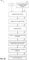
- an example method 300 may be used by computer device 102 ( Fig. 1 ) for converting an identified pin 39 ( Fig. 1 ) into a hardware loopback pin 18 ( Fig. 1 ) on a USB device 106 ( Fig. 1 ).
- the actions of method 300 may be discussed below with reference to the architecture of Fig. 1 .
- method 300 may include receiving an indication a device is connected with the computer device.
- USB stack 22 may detect a new connection to computer device 102 when a USB device 106 is plugged into, or otherwise connected to, computer device 102.
- method 300 may include locating an operating system specific firmware on the device.
- USB stack 22 may automatically locate and/or otherwise identify the OS specific firmware 30 on USB device 106 in response to detecting the new connection to computer device 102.
- the OS specific firmware 30 may identify at least one pin, e.g., microphone 17, on USB device 106 that may be converted into a hardware loopback pin 18. Once converted, microphone 17 may provide hardware loopback capabilities and may obtain hardware loopback stream 14.
- the OS specific firmware 30 may provide operating specific instructions for identifying the pin to convert it to a loopback pin.
- the OS specific firmware 30 may provide instructions specific to WINDOWS OS.
- the OS specific firmware 30 may be added to USB device 106 by the hardware manufacturer for USB device 106.
- method 300 may include translating the operating system firmware into configuration settings information.
- the OS specific firmware 30 may follow a standard format and the USB stack 22 may translate and/or convert the instructions provided in the OS specific firmware 30 into configuration settings information 26 for USB device 106.
- the configuration settings information 26 may specify a mapping that identifies which pin 39 to convert into a hardware loopback pin 18.
- method 300 may include creating a physical device object (PDO) for the device.
- USB stack 22 may create a physical device object (PDO) 24, such as a data structure associated with a bus driver according to a device and driver layering model, that represents the connection to the bus for USB device 106.
- PDO physical device object
- method 300 may optionally include identifying a driver to load for the physical device object.
- USB stack 22 may also determine a driver 36 for use with USB device 106.
- USB stack 22 may use one or more predefined rules in determining the appropriate driver 36 to use with USB device 106. For example, USB stack 22 may identify a USB audio class driver for use with USB device 106.
- method 300 may optionally include using a custom file to set the configuration settings information for the device.
- the custom file may be custom INF file 28 or any other setup information file for USB device 106.
- the configuration settings information 26 may be provided using a custom INF file 28.
- the custom INF file 28 may set a configuration in the registry on computer device 102 that identifies at least one pin 39 on USB device 106 that may be used as a hardware loopback pin 18.
- the custom INF file 28 may set values in the registry to specify a mapping that identifies which pin 39 to turn into a hardware loopback pin 18.
- method 300 may optionally include loading the driver for the physical device object.
- USB stack 22 may load driver 36 for the PDO 24.
- Operating system 110 may move the software program representing driver 36 and move it into memory 44 for execution by processor 42.
- USB stack 22 may find or otherwise locate a software module responsible for interfacing with USB device 106.
- the software module may be an in-box driver or other third party driver.
- An INF file may be used during the process to select a best driver and/or module to load into memory 44 to operate and/or use with USB device 106.
- method 300 may optionally include creating a functional device object (FDO) to represent the driver.
- FDO functional device object
- USB stack 22 may create a FDO 34, such as a data structure associated with a function driver at a layer above the PDO 24 according to a device and driver layering model, for the determine driver 36.
- method 300 may include initializing the device.
- Driver 36 may perform a device initialization 37.
- driver 36 may perform a device initialization 37 process for USB device 106.
- driver 36 may parse a device configuration descriptor for USB device 106 (e.g., the firmware for USB device 106) to identify the capture pins (e.g., microphone 17, 19) and/or render pins (e.g., speakers 20, 21) for USB device 106.
- Driver 36 may create a topology for USB device 106 and the identified capture and/or render pins.
- the device initialization 37 process may identify whether a specific capture pin (e.g., microphone 17) is designated as a hardware loopback pin 18 for USB device 106.
- method 300 may include reading the configuration settings information for the device.
- Driver 36 may also read the configuration settings information 26 for USB device 106.
- registry settings may store the configuration settings information 26 for USB device 106.
- Another example may include custom files may store the configuration settings information 26 for USB device 106.
- USB stack 22 may provide the configuration settings information 26 to driver 36.
- method 300 includes using the configuration settings information to identify at least one pin on the device.
- the configuration settings information 26 specifies which pins (e.g., microphones 17, 19) 17 on USB device 106 may be turned into a hardware loopback pin 18.
- Driver 36 uses the configuration settings information 26 to identify one or more pins 39 on USB device 106 that may be converted into a hardware loopback pin 18.
- Driver 36 performs a convert operation 38 to convert the identified pin 39 into a hardware loopback pin 18.
- the convert operation 38 may change the identified pin 39 from obtaining audio through microphone 17 and may connect microphone 17 to speakers 20, 21.
- Driver 36 provides instructions to USB device 106 to convert the identified pin 39 (e.g., microphone 17) into a hardware loopback pin 18.
- driver 36 may hide the identified capture pin 39 so that the identified capture pin 39 may not be visible in the user interface (UI) and may use the hardware loopback pin 18 for a hardware loopback stream 14.
- the hardware loopback pin 18 may be connected to a DAC Node on the render pin (e.g., speakers 20, 21) so that any audio on the render device is also captured by the hardware loopback pin 18.
- the identified pin 39 is changed from a pin to a hardware loopback pin 18 capable of providing a hardware loopback stream 14.
- method 300 includes receiving a hardware loopback stream using the hardware loopback pin.
- Driver 36 receives one or more hardware loopback streams 14 with the rendered audio data 15 from one or more hardware loopback pins 18 on USB devices 106.
- Hardware loopback streams 14 may accurately represent the audio data 15 output from speakers 20, 21 on USB device(s) 106.
- Method 300 includes providing the hardware loopback streams to one or more applications 10 executing on computer device 102.
- Driver 36 may provide the hardware loopback stream 14 to audio stack 16. Since the hardware loopback pin 18 is connected to the render pin (e.g., speakers 20, 21) through the DAC node, the rendered audio data 15 may be copied to the capture buffer.
- An application 10 requesting the loopback data may read the hardware loopback stream 14 from the capture buffer.
- Audio stack 16 may provide the hardware loopback stream 14 to one or more applications 10.
- Applications 10 may want to use the hardware loopback stream 14 for various processing.
- One example may include application 10 using the hardware loopback stream 14 to perform echo cancelation on audio output from one or more USB devices 106.
- capture stream 40 may include the audio from microphone 19 (e.g., the individual speaking) and audio from speaker 21 (e.g., background music).
- Application 10 may use the hardware loopback stream 14 to cancel out the audio from speaker 21 (e.g., the background music) so the friend does not hear the background music in the call.
- application 10 may want to record the audio emitted by one or more speakers 20, 21 on USB device 106.
- USB devices 106 Since hardware loopback corresponds more closely to the audio output by the USB devices 106 than a stored stream of data input to the speakers of the respective devices, a better representation of the audio output by the USB devices 106 may be used by the applications 10.
- method 300 may be used to provide hardware loopback capabilities to USB devices 106.
- USB devices 106 may be able to provide hardware loopback capabilities for use with applications 10.
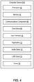
- computer 400 that may be configured as computer device 102 in accordance with an implementation includes additional component details as compared to Fig. 1 .
- computer 400 includes processor 42 for carrying out processing functions associated with one or more of components and functions described herein.
- processor 42 can include a single or multiple set of processors or multi-core processors.
- processor 42 can be implemented as an integrated processing system and/or a distributed processing system.
- Computer 400 further includes memory 44, such as for storing local versions of applications being executed by processor 42.
- Memory 44 can include a type of memory usable by a computer, such as random access memory (RAM), read only memory (ROM), tapes, magnetic discs, optical discs, volatile memory, non-volatile memory, and any combination thereof.
- processor 42 may include and execute operating system 110 ( Fig. 1 ).
- computer 400 may include a communications component 46 that provides for establishing and maintaining communications with one or more parties utilizing hardware, software, and services as described herein.
- Communications component 46 may carry communications between components on computer device 102, as well as between computer device 102 and external devices, such as devices located across a communications network and/or devices serially or locally connected to computer device 102.
- communications component 46 may include one or more buses, and may further include transmit chain components and receive chain components associated with a transmitter and receiver, respectively, operable for interfacing with external devices.
- computer 400 may include a data store 48, which can be any suitable combination of hardware and/or software, that provides for mass storage of information, databases, and programs employed in connection with implementations described herein.
- data store 48 may be a data repository for applications 10, audio stack 16, USB stack 22, and/or driver 36.
- Computer 400 may also include a user interface component 50 operable to receive inputs from a user of computer device 102 and further operable to generate outputs for presentation to the user.
- User interface component 50 may include one or more input devices, including but not limited to a keyboard, a number pad, a mouse, display (e.g., which may be a touch-sensitive display), a navigation key, a function key, a microphone, a voice recognition component, any other mechanism capable of receiving an input from a user, or any combination thereof.
- user interface component 50 may include one or more output devices, including but not limited to a display, a speaker, a haptic feedback mechanism, a printer, any other mechanism capable of presenting an output to a user, or any combination thereof.
- user interface component 50 may transmit and/or receive messages corresponding to the operation of applications 10, audio stack 16, USB stack 22, and/or driver 36.
- processor 42 executes applications 10, audio stack 16, USB stack 22, and/or driver 36, and memory 44 or data store 48 may store them.
- a component may be, but is not limited to being, a process running on a processor, a processor, an object, an executable, a thread of execution, a program, and/or a computer.
- an application running on a computer device and the computer device can be a component.
- One or more components can reside within a process and/or thread of execution and a component may be localized on one computer and/or distributed between two or more computers.
- these components can execute from various computer readable media having various data structures stored thereon.
- the components may communicate by way of local and/or remote processes such as in accordance with a signal having one or more data packets, such as data from one component interacting with another component in a local system, distributed system, and/or across a network such as the Internet with other systems by way of the signal.
- a signal having one or more data packets, such as data from one component interacting with another component in a local system, distributed system, and/or across a network such as the Internet with other systems by way of the signal.
- the term "or” is intended to mean an inclusive “or” rather than an exclusive “or.” That is, unless specified otherwise, or clear from the context, the phrase “X employs A or B” is intended to mean any of the natural inclusive permutations. That is, the phrase “X employs A or B” is satisfied by any of the following instances: X employs A; X employs B; or X employs both A and B.
- the articles “a” and “an” as used in this application and the appended claims should generally be construed to mean “one or more” unless specified otherwise or clear from the context to be directed to a singular form.
- DSP digital signal processor
- ASIC application specific integrated circuit
- FPGA field programmable gate array
- a general-purpose processor may be a microprocessor, but, in the alternative, the processor may be any conventional processor, controller, microcontroller, or state machine.
- a processor may also be implemented as a combination of computer devices, e.g., a combination of a DSP and a microprocessor, a plurality of microprocessors, one or more microprocessors in conjunction with a DSP core, or any other such configuration. Additionally, at least one processor may comprise one or more components operable to perform one or more of the steps and/or actions described above.
- a software module may reside in RAM memory, flash memory, ROM memory, EPROM memory, EEPROM memory, registers, a hard disk, a removable disk, a CD-ROM, or any other form of storage medium known in the art.
- An exemplary storage medium may be coupled to the processor, such that the processor can read information from, and write information to, the storage medium.
- the storage medium may be integral to the processor.
- the processor and the storage medium may reside in an ASIC. Additionally, the ASIC may reside in a user terminal.
- processor and the storage medium may reside as discrete components in a user terminal. Additionally, in some implementations, the steps and/or actions of a method or algorithm may reside as one or any combination or set of codes and/or instructions on a machine readable medium and/or computer readable medium, which may be incorporated into a computer program product.
- the functions described may be implemented in hardware, software, firmware, or any combination thereof. If implemented in software, the functions may be stored or transmitted as one or more instructions or code on a computer-readable medium.
- Computer-readable media includes both computer storage media and communication media including any medium that facilitates transfer of a computer program from one place to another.
- a storage medium may be any available media that can be accessed by a computer.
- such computer-readable media can comprise RAM, ROM, EEPROM, CD-ROM or other optical disk storage, magnetic disk storage or other magnetic storage devices, or any other medium that can be used to store desired program code in the form of instructions or data structures and that can be accessed by a computer.
- Disk and disc includes compact disc (CD), laser disc, optical disc, digital versatile disc (DVD), floppy disk and Blu-ray disc where disks usually reproduce data magnetically, while discs usually reproduce data optically with lasers. Combinations of the above should also be included within the scope of computer-readable media.
Landscapes
- Engineering & Computer Science (AREA)
- Theoretical Computer Science (AREA)
- Software Systems (AREA)
- Physics & Mathematics (AREA)
- General Engineering & Computer Science (AREA)
- General Physics & Mathematics (AREA)
- Information Transfer Systems (AREA)
Claims (15)
- Computervorrichtung, umfassend:einen Speicher zum Speichern von Daten und Anweisungen;mindestens einen Prozessor, der zum Kommunizieren mit dem Speicher konfiguriert ist, wobei der mindestens eine Prozessor konfiguriert ist zum:Verwenden (322) von Konfigurationseinstellungsinformationen zum Identifizieren von mindestens einem Stift auf einer Universal-Serial-Bus-, USB-, Vorrichtung in Kommunikation mit der Computervorrichtung,dadurch gekennzeichnet, dass der Prozessor ferner konfiguriert ist zum:Umwandeln (324) des mindestens einen Stifts in einen Hardware-Loopback-Stift auf der USB-Vorrichtung, wobei der Hardware-Loopback-Stift Audiodaten empfängt, die aktuell an einen Render-Stift auf der USB-Vorrichtung gerendert werden;Empfangen (326) eines Hardware-Loopback-Streams mit den Audiodaten von dem Hardware-Loopback-Stift auf der USB-Vorrichtung; undBereitstellen des Hardware-Loopback-Streams für eine oder mehrere Anwendungen, die auf der Computervorrichtung ausgeführt werden.
- Computervorrichtung nach Anspruch 1, wobei die Konfigurationseinstellungsinformationen in einer benutzerdefinierten Datei für die USB-Vorrichtung bereitgestellt werden.
- Computervorrichtung nach Anspruch 1, wobei die Konfigurationseinstellungsinformationen in der betriebssystemspezifischen Firmware auf der USB-Vorrichtung bereitgestellt werden.
- Computervorrichtung nach Anspruch 3, wobei in der betriebssystemspezifischen Firmware bereitgestellte Anweisungen in die Konfigurationseinstellungsinformationen übersetzt werden.
- Computervorrichtung nach Anspruch 1, wobei die Konfigurationseinstellungsinformationen eine Zuordnung des mindestens einen Stifts zum Umwandeln in den Hardware-Loopback-Stift bereitstellen.
- Computervorrichtung nach Anspruch 1, wobei der mindestens eine Prozessor ferner zum Umwandeln des mindestens einen Stifts in den Hardware-Loopback-Stift durch Bereitstellen von Anweisungen für die USB-Vorrichtung zum Verbinden des Hardware-Loopback-Stifts mit dem Render-Stift auf der USB-Vorrichtung betreibbar ist.
- Computervorrichtung nach Anspruch 1, wobei die eine oder mehreren Anwendungen den Hardware-Loopback-Stream für mindestens eines von Echounterdrückung oder Erstellen einer Aufzeichnung verwenden.
- Verfahren zum Umwandeln eines identifizierten Stifts in einen Hardware-Loopback-Stift auf einer Universal-Serial-Bus-, USB-, Vorrichtung in Kommunikation mit einer Computervorrichtung, wobei das Verfahren umfasst:Verwenden (322) von Konfigurationseinstellungsinformationen über einen Prozessor auf der Computervorrichtung zum Identifizieren von mindestens einem Stift auf der USB-Vorrichtung in Kommunikation mit der Computervorrichtung;Umwandeln (324) des mindestens einen Stifts über den Prozessor in einen Hardware-Loopback-Stift auf der USB-Vorrichtung, wobei der Hardware-Loopback-Stift Audiodaten empfängt, die aktuell an einen Render-Stift auf der USB-Vorrichtung gerendert werden;Empfangen (326) eines Hardware-Loopback-Streams mit den Audiodaten von dem Hardware-Loopback-Stift auf der USB-Vorrichtung; undBereitstellen des Hardware-Loopback-Streams für eine oder mehrere Anwendungen, die auf der Computervorrichtung ausgeführt werden.
- Verfahren nach Anspruch 8, wobei die Konfigurationseinstellungsinformationen in einer benutzerdefinierten Datei für die USB-Vorrichtung bereitgestellt werden.
- Verfahren nach Anspruch 8, wobei die Konfigurationseinstellungsinformationen in der betriebssystemspezifischen Firmware auf der USB-Vorrichtung bereitgestellt werden.
- Verfahren nach Anspruch 10, wobei das Verfahren ferner umfasst:
Übersetzen der in der betriebssystemspezifischen Firmware bereitgestellten Anweisungen in die Konfigurationseinstellungsinformationen. - Verfahren nach Anspruch 8, wobei die Konfigurationseinstellungsinformationen eine Zuordnung des mindestens einen Stifts zum Umwandeln in den Hardware-Loopback-Stift bereitstellen.
- Verfahren nach Anspruch 8, wobei das Umwandeln des mindestens einen Stifts in den Hardware-Loopback-Stift ferner Bereitstellen von Anweisungen für die USB-Vorrichtung zum Verbinden des Hardware-Loopback-Stifts mit dem Render-Stift auf der USB-Vorrichtung umfasst.
- Verfahren nach Anspruch 8, wobei die eine oder mehreren Anwendungen den Hardware-Loopback-Stream für mindestens eines aus Echounterdrückung oder Erstellen einer Aufzeichnung verwenden.
- Computerlesbares Medium, auf dem durch eine Computervorrichtung ausführbare Anweisungen gespeichert sind, umfassend mindestens eine Anweisung zur Veranlassung der Computervorrichtung zum Durchführen des Verfahrens nach Anspruch 8.
Applications Claiming Priority (2)
| Application Number | Priority Date | Filing Date | Title |
|---|---|---|---|
| US16/571,864 US10909049B1 (en) | 2019-09-16 | 2019-09-16 | Converting a pin into a loopback pin |
| PCT/US2020/038305 WO2021055047A1 (en) | 2019-09-16 | 2020-06-18 | Converting a pin into a loopback pin |
Publications (2)
| Publication Number | Publication Date |
|---|---|
| EP4031983A1 EP4031983A1 (de) | 2022-07-27 |
| EP4031983B1 true EP4031983B1 (de) | 2024-08-14 |
Family
ID=71465475
Family Applications (1)
| Application Number | Title | Priority Date | Filing Date |
|---|---|---|---|
| EP20736879.6A Active EP4031983B1 (de) | 2019-09-16 | 2020-06-18 | Umwandlung eines stiftes in einen loopback-stift |
Country Status (4)
| Country | Link |
|---|---|
| US (1) | US10909049B1 (de) |
| EP (1) | EP4031983B1 (de) |
| CN (1) | CN114391140B (de) |
| WO (1) | WO2021055047A1 (de) |
Family Cites Families (5)
| Publication number | Priority date | Publication date | Assignee | Title |
|---|---|---|---|---|
| US6590604B1 (en) * | 2000-04-07 | 2003-07-08 | Polycom, Inc. | Personal videoconferencing system having distributed processing architecture |
| TWI380184B (en) * | 2008-11-04 | 2012-12-21 | Wistron Corp | Signal transmission path selecting circuit and method and electronic device applying the circuit |
| US20140163716A1 (en) * | 2012-12-10 | 2014-06-12 | Skymedi Corporation | Bridge device, automated production system and method thereof for storage device |
| GB2552559A (en) | 2016-07-25 | 2018-01-31 | Cirrus Logic Int Semiconductor Ltd | Connectors for data transfer |
| CN107678985B (zh) | 2017-09-06 | 2020-05-05 | 苏州佳世达光电有限公司 | 显示装置及讯号来源切换方法 |
-
2019
- 2019-09-16 US US16/571,864 patent/US10909049B1/en active Active
-
2020
- 2020-06-18 EP EP20736879.6A patent/EP4031983B1/de active Active
- 2020-06-18 CN CN202080064337.2A patent/CN114391140B/zh active Active
- 2020-06-18 WO PCT/US2020/038305 patent/WO2021055047A1/en not_active Ceased
Also Published As
| Publication number | Publication date |
|---|---|
| WO2021055047A1 (en) | 2021-03-25 |
| CN114391140B (zh) | 2024-07-30 |
| CN114391140A (zh) | 2022-04-22 |
| US10909049B1 (en) | 2021-02-02 |
| EP4031983A1 (de) | 2022-07-27 |
Similar Documents
| Publication | Publication Date | Title |
|---|---|---|
| CN108564966B (zh) | 语音测试的方法及其设备、具有存储功能的装置 | |
| CN105378646B (zh) | 多种同时音频模式的方法与设备 | |
| CN113094123A (zh) | 应用程序中功能的实现方法、装置、电子设备和存储介质 | |
| US10149089B1 (en) | Remote personalization of audio | |
| CN112579038B (zh) | 一种内置录音方法、装置、电子设备和存储介质 | |
| CN111506291A (zh) | 音频数据采集方法、装置、计算机设备及存储介质 | |
| US9368095B2 (en) | Method for outputting sound and apparatus for the same | |
| CN106170037A (zh) | 音频播放控制方法及装置 | |
| WO2018126613A1 (zh) | 一种音频数据播放方法和双屏移动终端 | |
| CN111625214A (zh) | 音频控制方法、装置、设备及存储介质 | |
| CN111601154A (zh) | 一种视频处理方法及相关设备 | |
| EP4031983B1 (de) | Umwandlung eines stiftes in einen loopback-stift | |
| WO2020215704A1 (zh) | 能够实现桌面共享的即时通信方法及相关装置 | |
| CN107566595A (zh) | 移动终端的音量控制方法、装置及存储介质和移动终端 | |
| CN113892080B (zh) | 将多个端点表示为一个端点的设备聚合 | |
| CN113841426A (zh) | 使用应用位置信息向各种通道发送音频 | |
| CN112882685A (zh) | 面向对象编程语言的对象的扩展方法及装置 | |
| CN113889154B (zh) | 声音录制方法、终端、存储介质 | |
| EP3963439B1 (de) | Aggregieren einer hardware-prüfschleife | |
| US10642839B2 (en) | Associating hardware to store applications | |
| CN104767869B (zh) | 一种终端及其声控方法 | |
| CN109445873B (zh) | 显示设置界面的方法和装置 | |
| CN116567484A (zh) | 多麦克风录音方法、装置、电子设备及存储介质 | |
| CN117762762A (zh) | 自动化测试方法、装置、电子设备及存储介质 | |
| CN117597902A (zh) | 音频处理系统、方法、电子设备及存储介质 |
Legal Events
| Date | Code | Title | Description |
|---|---|---|---|
| STAA | Information on the status of an ep patent application or granted ep patent |
Free format text: STATUS: UNKNOWN |
|
| STAA | Information on the status of an ep patent application or granted ep patent |
Free format text: STATUS: THE INTERNATIONAL PUBLICATION HAS BEEN MADE |
|
| PUAI | Public reference made under article 153(3) epc to a published international application that has entered the european phase |
Free format text: ORIGINAL CODE: 0009012 |
|
| STAA | Information on the status of an ep patent application or granted ep patent |
Free format text: STATUS: REQUEST FOR EXAMINATION WAS MADE |
|
| 17P | Request for examination filed |
Effective date: 20220315 |
|
| AK | Designated contracting states |
Kind code of ref document: A1 Designated state(s): AL AT BE BG CH CY CZ DE DK EE ES FI FR GB GR HR HU IE IS IT LI LT LU LV MC MK MT NL NO PL PT RO RS SE SI SK SM TR |
|
| DAV | Request for validation of the european patent (deleted) | ||
| DAX | Request for extension of the european patent (deleted) | ||
| STAA | Information on the status of an ep patent application or granted ep patent |
Free format text: STATUS: EXAMINATION IS IN PROGRESS |
|
| 17Q | First examination report despatched |
Effective date: 20230804 |
|
| GRAP | Despatch of communication of intention to grant a patent |
Free format text: ORIGINAL CODE: EPIDOSNIGR1 |
|
| STAA | Information on the status of an ep patent application or granted ep patent |
Free format text: STATUS: GRANT OF PATENT IS INTENDED |
|
| INTG | Intention to grant announced |
Effective date: 20240328 |
|
| GRAS | Grant fee paid |
Free format text: ORIGINAL CODE: EPIDOSNIGR3 |
|
| GRAA | (expected) grant |
Free format text: ORIGINAL CODE: 0009210 |
|
| STAA | Information on the status of an ep patent application or granted ep patent |
Free format text: STATUS: THE PATENT HAS BEEN GRANTED |
|
| P01 | Opt-out of the competence of the unified patent court (upc) registered |
Free format text: CASE NUMBER: APP_35426/2024 Effective date: 20240612 |
|
| AK | Designated contracting states |
Kind code of ref document: B1 Designated state(s): AL AT BE BG CH CY CZ DE DK EE ES FI FR GB GR HR HU IE IS IT LI LT LU LV MC MK MT NL NO PL PT RO RS SE SI SK SM TR |
|
| REG | Reference to a national code |
Ref country code: GB Ref legal event code: FG4D |
|
| REG | Reference to a national code |
Ref country code: CH Ref legal event code: EP |
|
| REG | Reference to a national code |
Ref country code: DE Ref legal event code: R096 Ref document number: 602020035766 Country of ref document: DE |
|
| REG | Reference to a national code |
Ref country code: IE Ref legal event code: FG4D |
|
| REG | Reference to a national code |
Ref country code: LT Ref legal event code: MG9D |
|
| REG | Reference to a national code |
Ref country code: NL Ref legal event code: MP Effective date: 20240814 |
|
| PG25 | Lapsed in a contracting state [announced via postgrant information from national office to epo] |
Ref country code: NO Free format text: LAPSE BECAUSE OF FAILURE TO SUBMIT A TRANSLATION OF THE DESCRIPTION OR TO PAY THE FEE WITHIN THE PRESCRIBED TIME-LIMIT Effective date: 20241114 |
|
| REG | Reference to a national code |
Ref country code: AT Ref legal event code: MK05 Ref document number: 1713950 Country of ref document: AT Kind code of ref document: T Effective date: 20240814 |
|
| PG25 | Lapsed in a contracting state [announced via postgrant information from national office to epo] |
Ref country code: PT Free format text: LAPSE BECAUSE OF FAILURE TO SUBMIT A TRANSLATION OF THE DESCRIPTION OR TO PAY THE FEE WITHIN THE PRESCRIBED TIME-LIMIT Effective date: 20241216 Ref country code: NL Free format text: LAPSE BECAUSE OF FAILURE TO SUBMIT A TRANSLATION OF THE DESCRIPTION OR TO PAY THE FEE WITHIN THE PRESCRIBED TIME-LIMIT Effective date: 20240814 Ref country code: PL Free format text: LAPSE BECAUSE OF FAILURE TO SUBMIT A TRANSLATION OF THE DESCRIPTION OR TO PAY THE FEE WITHIN THE PRESCRIBED TIME-LIMIT Effective date: 20240814 Ref country code: GR Free format text: LAPSE BECAUSE OF FAILURE TO SUBMIT A TRANSLATION OF THE DESCRIPTION OR TO PAY THE FEE WITHIN THE PRESCRIBED TIME-LIMIT Effective date: 20241115 Ref country code: FI Free format text: LAPSE BECAUSE OF FAILURE TO SUBMIT A TRANSLATION OF THE DESCRIPTION OR TO PAY THE FEE WITHIN THE PRESCRIBED TIME-LIMIT Effective date: 20240814 |
|
| PG25 | Lapsed in a contracting state [announced via postgrant information from national office to epo] |
Ref country code: BG Free format text: LAPSE BECAUSE OF FAILURE TO SUBMIT A TRANSLATION OF THE DESCRIPTION OR TO PAY THE FEE WITHIN THE PRESCRIBED TIME-LIMIT Effective date: 20240814 |
|
| PG25 | Lapsed in a contracting state [announced via postgrant information from national office to epo] |
Ref country code: LV Free format text: LAPSE BECAUSE OF FAILURE TO SUBMIT A TRANSLATION OF THE DESCRIPTION OR TO PAY THE FEE WITHIN THE PRESCRIBED TIME-LIMIT Effective date: 20240814 |
|
| PG25 | Lapsed in a contracting state [announced via postgrant information from national office to epo] |
Ref country code: IS Free format text: LAPSE BECAUSE OF FAILURE TO SUBMIT A TRANSLATION OF THE DESCRIPTION OR TO PAY THE FEE WITHIN THE PRESCRIBED TIME-LIMIT Effective date: 20241214 Ref country code: AT Free format text: LAPSE BECAUSE OF FAILURE TO SUBMIT A TRANSLATION OF THE DESCRIPTION OR TO PAY THE FEE WITHIN THE PRESCRIBED TIME-LIMIT Effective date: 20240814 |
|
| PG25 | Lapsed in a contracting state [announced via postgrant information from national office to epo] |
Ref country code: HR Free format text: LAPSE BECAUSE OF FAILURE TO SUBMIT A TRANSLATION OF THE DESCRIPTION OR TO PAY THE FEE WITHIN THE PRESCRIBED TIME-LIMIT Effective date: 20240814 |
|
| PG25 | Lapsed in a contracting state [announced via postgrant information from national office to epo] |
Ref country code: RS Free format text: LAPSE BECAUSE OF FAILURE TO SUBMIT A TRANSLATION OF THE DESCRIPTION OR TO PAY THE FEE WITHIN THE PRESCRIBED TIME-LIMIT Effective date: 20241114 Ref country code: ES Free format text: LAPSE BECAUSE OF FAILURE TO SUBMIT A TRANSLATION OF THE DESCRIPTION OR TO PAY THE FEE WITHIN THE PRESCRIBED TIME-LIMIT Effective date: 20240814 |
|
| PG25 | Lapsed in a contracting state [announced via postgrant information from national office to epo] |
Ref country code: RS Free format text: LAPSE BECAUSE OF FAILURE TO SUBMIT A TRANSLATION OF THE DESCRIPTION OR TO PAY THE FEE WITHIN THE PRESCRIBED TIME-LIMIT Effective date: 20241114 Ref country code: PT Free format text: LAPSE BECAUSE OF FAILURE TO SUBMIT A TRANSLATION OF THE DESCRIPTION OR TO PAY THE FEE WITHIN THE PRESCRIBED TIME-LIMIT Effective date: 20241216 Ref country code: PL Free format text: LAPSE BECAUSE OF FAILURE TO SUBMIT A TRANSLATION OF THE DESCRIPTION OR TO PAY THE FEE WITHIN THE PRESCRIBED TIME-LIMIT Effective date: 20240814 Ref country code: NO Free format text: LAPSE BECAUSE OF FAILURE TO SUBMIT A TRANSLATION OF THE DESCRIPTION OR TO PAY THE FEE WITHIN THE PRESCRIBED TIME-LIMIT Effective date: 20241114 Ref country code: NL Free format text: LAPSE BECAUSE OF FAILURE TO SUBMIT A TRANSLATION OF THE DESCRIPTION OR TO PAY THE FEE WITHIN THE PRESCRIBED TIME-LIMIT Effective date: 20240814 Ref country code: LV Free format text: LAPSE BECAUSE OF FAILURE TO SUBMIT A TRANSLATION OF THE DESCRIPTION OR TO PAY THE FEE WITHIN THE PRESCRIBED TIME-LIMIT Effective date: 20240814 Ref country code: IS Free format text: LAPSE BECAUSE OF FAILURE TO SUBMIT A TRANSLATION OF THE DESCRIPTION OR TO PAY THE FEE WITHIN THE PRESCRIBED TIME-LIMIT Effective date: 20241214 Ref country code: HR Free format text: LAPSE BECAUSE OF FAILURE TO SUBMIT A TRANSLATION OF THE DESCRIPTION OR TO PAY THE FEE WITHIN THE PRESCRIBED TIME-LIMIT Effective date: 20240814 Ref country code: GR Free format text: LAPSE BECAUSE OF FAILURE TO SUBMIT A TRANSLATION OF THE DESCRIPTION OR TO PAY THE FEE WITHIN THE PRESCRIBED TIME-LIMIT Effective date: 20241115 Ref country code: FI Free format text: LAPSE BECAUSE OF FAILURE TO SUBMIT A TRANSLATION OF THE DESCRIPTION OR TO PAY THE FEE WITHIN THE PRESCRIBED TIME-LIMIT Effective date: 20240814 Ref country code: ES Free format text: LAPSE BECAUSE OF FAILURE TO SUBMIT A TRANSLATION OF THE DESCRIPTION OR TO PAY THE FEE WITHIN THE PRESCRIBED TIME-LIMIT Effective date: 20240814 Ref country code: BG Free format text: LAPSE BECAUSE OF FAILURE TO SUBMIT A TRANSLATION OF THE DESCRIPTION OR TO PAY THE FEE WITHIN THE PRESCRIBED TIME-LIMIT Effective date: 20240814 Ref country code: AT Free format text: LAPSE BECAUSE OF FAILURE TO SUBMIT A TRANSLATION OF THE DESCRIPTION OR TO PAY THE FEE WITHIN THE PRESCRIBED TIME-LIMIT Effective date: 20240814 |
|
| PG25 | Lapsed in a contracting state [announced via postgrant information from national office to epo] |
Ref country code: DK Free format text: LAPSE BECAUSE OF FAILURE TO SUBMIT A TRANSLATION OF THE DESCRIPTION OR TO PAY THE FEE WITHIN THE PRESCRIBED TIME-LIMIT Effective date: 20240814 Ref country code: RO Free format text: LAPSE BECAUSE OF FAILURE TO SUBMIT A TRANSLATION OF THE DESCRIPTION OR TO PAY THE FEE WITHIN THE PRESCRIBED TIME-LIMIT Effective date: 20240814 Ref country code: SM Free format text: LAPSE BECAUSE OF FAILURE TO SUBMIT A TRANSLATION OF THE DESCRIPTION OR TO PAY THE FEE WITHIN THE PRESCRIBED TIME-LIMIT Effective date: 20240814 |
|
| PG25 | Lapsed in a contracting state [announced via postgrant information from national office to epo] |
Ref country code: EE Free format text: LAPSE BECAUSE OF FAILURE TO SUBMIT A TRANSLATION OF THE DESCRIPTION OR TO PAY THE FEE WITHIN THE PRESCRIBED TIME-LIMIT Effective date: 20240814 |
|
| PG25 | Lapsed in a contracting state [announced via postgrant information from national office to epo] |
Ref country code: CZ Free format text: LAPSE BECAUSE OF FAILURE TO SUBMIT A TRANSLATION OF THE DESCRIPTION OR TO PAY THE FEE WITHIN THE PRESCRIBED TIME-LIMIT Effective date: 20240814 |
|
| PG25 | Lapsed in a contracting state [announced via postgrant information from national office to epo] |
Ref country code: SK Free format text: LAPSE BECAUSE OF FAILURE TO SUBMIT A TRANSLATION OF THE DESCRIPTION OR TO PAY THE FEE WITHIN THE PRESCRIBED TIME-LIMIT Effective date: 20240814 Ref country code: IT Free format text: LAPSE BECAUSE OF FAILURE TO SUBMIT A TRANSLATION OF THE DESCRIPTION OR TO PAY THE FEE WITHIN THE PRESCRIBED TIME-LIMIT Effective date: 20240814 |
|
| REG | Reference to a national code |
Ref country code: DE Ref legal event code: R097 Ref document number: 602020035766 Country of ref document: DE |
|
| PLBE | No opposition filed within time limit |
Free format text: ORIGINAL CODE: 0009261 |
|
| STAA | Information on the status of an ep patent application or granted ep patent |
Free format text: STATUS: NO OPPOSITION FILED WITHIN TIME LIMIT |
|
| PGFP | Annual fee paid to national office [announced via postgrant information from national office to epo] |
Ref country code: DE Payment date: 20250520 Year of fee payment: 6 |
|
| PGFP | Annual fee paid to national office [announced via postgrant information from national office to epo] |
Ref country code: GB Payment date: 20250520 Year of fee payment: 6 |
|
| 26N | No opposition filed |
Effective date: 20250515 |
|
| PG25 | Lapsed in a contracting state [announced via postgrant information from national office to epo] |
Ref country code: SE Free format text: LAPSE BECAUSE OF FAILURE TO SUBMIT A TRANSLATION OF THE DESCRIPTION OR TO PAY THE FEE WITHIN THE PRESCRIBED TIME-LIMIT Effective date: 20240814 |
|
| REG | Reference to a national code |
Ref country code: CH Ref legal event code: H13 Free format text: ST27 STATUS EVENT CODE: U-0-0-H10-H13 (AS PROVIDED BY THE NATIONAL OFFICE) Effective date: 20260127 |
|
| PG25 | Lapsed in a contracting state [announced via postgrant information from national office to epo] |
Ref country code: MC Free format text: LAPSE BECAUSE OF FAILURE TO SUBMIT A TRANSLATION OF THE DESCRIPTION OR TO PAY THE FEE WITHIN THE PRESCRIBED TIME-LIMIT Effective date: 20240814 |
|
| PG25 | Lapsed in a contracting state [announced via postgrant information from national office to epo] |
Ref country code: LU Free format text: LAPSE BECAUSE OF NON-PAYMENT OF DUE FEES Effective date: 20250618 |
|
| REG | Reference to a national code |
Ref country code: BE Ref legal event code: MM Effective date: 20250630 |
|
| PG25 | Lapsed in a contracting state [announced via postgrant information from national office to epo] |
Ref country code: IE Free format text: LAPSE BECAUSE OF NON-PAYMENT OF DUE FEES Effective date: 20250618 |
|
| PG25 | Lapsed in a contracting state [announced via postgrant information from national office to epo] |
Ref country code: BE Free format text: LAPSE BECAUSE OF NON-PAYMENT OF DUE FEES Effective date: 20250630 |
|
| PG25 | Lapsed in a contracting state [announced via postgrant information from national office to epo] |
Ref country code: FR Free format text: LAPSE BECAUSE OF NON-PAYMENT OF DUE FEES Effective date: 20250630 |
|
| PG25 | Lapsed in a contracting state [announced via postgrant information from national office to epo] |
Ref country code: CH Free format text: LAPSE BECAUSE OF NON-PAYMENT OF DUE FEES Effective date: 20250630 |