EP4031796B1 - Wärmemanagement in anpassbaren tanks - Google Patents
Wärmemanagement in anpassbaren tanks Download PDFInfo
- Publication number
- EP4031796B1 EP4031796B1 EP20865724.7A EP20865724A EP4031796B1 EP 4031796 B1 EP4031796 B1 EP 4031796B1 EP 20865724 A EP20865724 A EP 20865724A EP 4031796 B1 EP4031796 B1 EP 4031796B1
- Authority
- EP
- European Patent Office
- Prior art keywords
- pressure vessel
- gas
- conformable
- segments
- vessel segments
- Prior art date
- Legal status (The legal status is an assumption and is not a legal conclusion. Google has not performed a legal analysis and makes no representation as to the accuracy of the status listed.)
- Active
Links
Images


Classifications
-
- F—MECHANICAL ENGINEERING; LIGHTING; HEATING; WEAPONS; BLASTING
- F17—STORING OR DISTRIBUTING GASES OR LIQUIDS
- F17C—VESSELS FOR CONTAINING OR STORING COMPRESSED, LIQUEFIED OR SOLIDIFIED GASES; FIXED-CAPACITY GAS-HOLDERS; FILLING VESSELS WITH, OR DISCHARGING FROM VESSELS, COMPRESSED, LIQUEFIED, OR SOLIDIFIED GASES
- F17C1/00—Pressure vessels, e.g. gas cylinder, gas tank, replaceable cartridge
- F17C1/02—Pressure vessels, e.g. gas cylinder, gas tank, replaceable cartridge involving reinforcing arrangements
-
- F—MECHANICAL ENGINEERING; LIGHTING; HEATING; WEAPONS; BLASTING
- F17—STORING OR DISTRIBUTING GASES OR LIQUIDS
- F17C—VESSELS FOR CONTAINING OR STORING COMPRESSED, LIQUEFIED OR SOLIDIFIED GASES; FIXED-CAPACITY GAS-HOLDERS; FILLING VESSELS WITH, OR DISCHARGING FROM VESSELS, COMPRESSED, LIQUEFIED, OR SOLIDIFIED GASES
- F17C1/00—Pressure vessels, e.g. gas cylinder, gas tank, replaceable cartridge
-
- F—MECHANICAL ENGINEERING; LIGHTING; HEATING; WEAPONS; BLASTING
- F17—STORING OR DISTRIBUTING GASES OR LIQUIDS
- F17C—VESSELS FOR CONTAINING OR STORING COMPRESSED, LIQUEFIED OR SOLIDIFIED GASES; FIXED-CAPACITY GAS-HOLDERS; FILLING VESSELS WITH, OR DISCHARGING FROM VESSELS, COMPRESSED, LIQUEFIED, OR SOLIDIFIED GASES
- F17C2201/00—Vessel construction, in particular geometry, arrangement or size
- F17C2201/01—Shape
- F17C2201/0138—Shape tubular
-
- F—MECHANICAL ENGINEERING; LIGHTING; HEATING; WEAPONS; BLASTING
- F17—STORING OR DISTRIBUTING GASES OR LIQUIDS
- F17C—VESSELS FOR CONTAINING OR STORING COMPRESSED, LIQUEFIED OR SOLIDIFIED GASES; FIXED-CAPACITY GAS-HOLDERS; FILLING VESSELS WITH, OR DISCHARGING FROM VESSELS, COMPRESSED, LIQUEFIED, OR SOLIDIFIED GASES
- F17C2201/00—Vessel construction, in particular geometry, arrangement or size
- F17C2201/05—Size
- F17C2201/054—Size medium (>1 m3)
-
- F—MECHANICAL ENGINEERING; LIGHTING; HEATING; WEAPONS; BLASTING
- F17—STORING OR DISTRIBUTING GASES OR LIQUIDS
- F17C—VESSELS FOR CONTAINING OR STORING COMPRESSED, LIQUEFIED OR SOLIDIFIED GASES; FIXED-CAPACITY GAS-HOLDERS; FILLING VESSELS WITH, OR DISCHARGING FROM VESSELS, COMPRESSED, LIQUEFIED, OR SOLIDIFIED GASES
- F17C2201/00—Vessel construction, in particular geometry, arrangement or size
- F17C2201/05—Size
- F17C2201/056—Small (<1 m3)
-
- F—MECHANICAL ENGINEERING; LIGHTING; HEATING; WEAPONS; BLASTING
- F17—STORING OR DISTRIBUTING GASES OR LIQUIDS
- F17C—VESSELS FOR CONTAINING OR STORING COMPRESSED, LIQUEFIED OR SOLIDIFIED GASES; FIXED-CAPACITY GAS-HOLDERS; FILLING VESSELS WITH, OR DISCHARGING FROM VESSELS, COMPRESSED, LIQUEFIED, OR SOLIDIFIED GASES
- F17C2203/00—Vessel construction, in particular walls or details thereof
- F17C2203/06—Materials for walls or layers thereof; Properties or structures of walls or their materials
- F17C2203/0602—Wall structures; Special features thereof
- F17C2203/0604—Liners
-
- F—MECHANICAL ENGINEERING; LIGHTING; HEATING; WEAPONS; BLASTING
- F17—STORING OR DISTRIBUTING GASES OR LIQUIDS
- F17C—VESSELS FOR CONTAINING OR STORING COMPRESSED, LIQUEFIED OR SOLIDIFIED GASES; FIXED-CAPACITY GAS-HOLDERS; FILLING VESSELS WITH, OR DISCHARGING FROM VESSELS, COMPRESSED, LIQUEFIED, OR SOLIDIFIED GASES
- F17C2203/00—Vessel construction, in particular walls or details thereof
- F17C2203/06—Materials for walls or layers thereof; Properties or structures of walls or their materials
- F17C2203/0634—Materials for walls or layers thereof
- F17C2203/0658—Synthetics
- F17C2203/066—Plastics
-
- F—MECHANICAL ENGINEERING; LIGHTING; HEATING; WEAPONS; BLASTING
- F17—STORING OR DISTRIBUTING GASES OR LIQUIDS
- F17C—VESSELS FOR CONTAINING OR STORING COMPRESSED, LIQUEFIED OR SOLIDIFIED GASES; FIXED-CAPACITY GAS-HOLDERS; FILLING VESSELS WITH, OR DISCHARGING FROM VESSELS, COMPRESSED, LIQUEFIED, OR SOLIDIFIED GASES
- F17C2203/00—Vessel construction, in particular walls or details thereof
- F17C2203/06—Materials for walls or layers thereof; Properties or structures of walls or their materials
- F17C2203/0634—Materials for walls or layers thereof
- F17C2203/0658—Synthetics
- F17C2203/0663—Synthetics in form of fibers or filaments
-
- F—MECHANICAL ENGINEERING; LIGHTING; HEATING; WEAPONS; BLASTING
- F17—STORING OR DISTRIBUTING GASES OR LIQUIDS
- F17C—VESSELS FOR CONTAINING OR STORING COMPRESSED, LIQUEFIED OR SOLIDIFIED GASES; FIXED-CAPACITY GAS-HOLDERS; FILLING VESSELS WITH, OR DISCHARGING FROM VESSELS, COMPRESSED, LIQUEFIED, OR SOLIDIFIED GASES
- F17C2205/00—Vessel construction, in particular mounting arrangements, attachments or identifications means
- F17C2205/01—Mounting arrangements
- F17C2205/0103—Exterior arrangements
- F17C2205/0107—Frames
-
- F—MECHANICAL ENGINEERING; LIGHTING; HEATING; WEAPONS; BLASTING
- F17—STORING OR DISTRIBUTING GASES OR LIQUIDS
- F17C—VESSELS FOR CONTAINING OR STORING COMPRESSED, LIQUEFIED OR SOLIDIFIED GASES; FIXED-CAPACITY GAS-HOLDERS; FILLING VESSELS WITH, OR DISCHARGING FROM VESSELS, COMPRESSED, LIQUEFIED, OR SOLIDIFIED GASES
- F17C2205/00—Vessel construction, in particular mounting arrangements, attachments or identifications means
- F17C2205/01—Mounting arrangements
- F17C2205/0103—Exterior arrangements
- F17C2205/0111—Boxes
-
- F—MECHANICAL ENGINEERING; LIGHTING; HEATING; WEAPONS; BLASTING
- F17—STORING OR DISTRIBUTING GASES OR LIQUIDS
- F17C—VESSELS FOR CONTAINING OR STORING COMPRESSED, LIQUEFIED OR SOLIDIFIED GASES; FIXED-CAPACITY GAS-HOLDERS; FILLING VESSELS WITH, OR DISCHARGING FROM VESSELS, COMPRESSED, LIQUEFIED, OR SOLIDIFIED GASES
- F17C2205/00—Vessel construction, in particular mounting arrangements, attachments or identifications means
- F17C2205/01—Mounting arrangements
- F17C2205/0123—Mounting arrangements characterised by number of vessels
- F17C2205/0126—One vessel
-
- F—MECHANICAL ENGINEERING; LIGHTING; HEATING; WEAPONS; BLASTING
- F17—STORING OR DISTRIBUTING GASES OR LIQUIDS
- F17C—VESSELS FOR CONTAINING OR STORING COMPRESSED, LIQUEFIED OR SOLIDIFIED GASES; FIXED-CAPACITY GAS-HOLDERS; FILLING VESSELS WITH, OR DISCHARGING FROM VESSELS, COMPRESSED, LIQUEFIED, OR SOLIDIFIED GASES
- F17C2205/00—Vessel construction, in particular mounting arrangements, attachments or identifications means
- F17C2205/03—Fluid connections, filters, valves, closure means or other attachments
- F17C2205/0302—Fittings, valves, filters, or components in connection with the gas storage device
- F17C2205/0323—Valves
-
- F—MECHANICAL ENGINEERING; LIGHTING; HEATING; WEAPONS; BLASTING
- F17—STORING OR DISTRIBUTING GASES OR LIQUIDS
- F17C—VESSELS FOR CONTAINING OR STORING COMPRESSED, LIQUEFIED OR SOLIDIFIED GASES; FIXED-CAPACITY GAS-HOLDERS; FILLING VESSELS WITH, OR DISCHARGING FROM VESSELS, COMPRESSED, LIQUEFIED, OR SOLIDIFIED GASES
- F17C2205/00—Vessel construction, in particular mounting arrangements, attachments or identifications means
- F17C2205/03—Fluid connections, filters, valves, closure means or other attachments
- F17C2205/0302—Fittings, valves, filters, or components in connection with the gas storage device
- F17C2205/035—Flow reducers
-
- F—MECHANICAL ENGINEERING; LIGHTING; HEATING; WEAPONS; BLASTING
- F17—STORING OR DISTRIBUTING GASES OR LIQUIDS
- F17C—VESSELS FOR CONTAINING OR STORING COMPRESSED, LIQUEFIED OR SOLIDIFIED GASES; FIXED-CAPACITY GAS-HOLDERS; FILLING VESSELS WITH, OR DISCHARGING FROM VESSELS, COMPRESSED, LIQUEFIED, OR SOLIDIFIED GASES
- F17C2205/00—Vessel construction, in particular mounting arrangements, attachments or identifications means
- F17C2205/03—Fluid connections, filters, valves, closure means or other attachments
- F17C2205/0388—Arrangement of valves, regulators, filters
- F17C2205/0394—Arrangement of valves, regulators, filters in direct contact with the pressure vessel
- F17C2205/0397—Arrangement of valves, regulators, filters in direct contact with the pressure vessel on both sides of the pressure vessel
-
- F—MECHANICAL ENGINEERING; LIGHTING; HEATING; WEAPONS; BLASTING
- F17—STORING OR DISTRIBUTING GASES OR LIQUIDS
- F17C—VESSELS FOR CONTAINING OR STORING COMPRESSED, LIQUEFIED OR SOLIDIFIED GASES; FIXED-CAPACITY GAS-HOLDERS; FILLING VESSELS WITH, OR DISCHARGING FROM VESSELS, COMPRESSED, LIQUEFIED, OR SOLIDIFIED GASES
- F17C2223/00—Handled fluid before transfer, i.e. state of fluid when stored in the vessel or before transfer from the vessel
- F17C2223/01—Handled fluid before transfer, i.e. state of fluid when stored in the vessel or before transfer from the vessel characterised by the phase
- F17C2223/0107—Single phase
- F17C2223/0123—Single phase gaseous, e.g. CNG, GNC
-
- F—MECHANICAL ENGINEERING; LIGHTING; HEATING; WEAPONS; BLASTING
- F17—STORING OR DISTRIBUTING GASES OR LIQUIDS
- F17C—VESSELS FOR CONTAINING OR STORING COMPRESSED, LIQUEFIED OR SOLIDIFIED GASES; FIXED-CAPACITY GAS-HOLDERS; FILLING VESSELS WITH, OR DISCHARGING FROM VESSELS, COMPRESSED, LIQUEFIED, OR SOLIDIFIED GASES
- F17C2223/00—Handled fluid before transfer, i.e. state of fluid when stored in the vessel or before transfer from the vessel
- F17C2223/03—Handled fluid before transfer, i.e. state of fluid when stored in the vessel or before transfer from the vessel characterised by the pressure level
- F17C2223/036—Very high pressure (>80 bar)
-
- F—MECHANICAL ENGINEERING; LIGHTING; HEATING; WEAPONS; BLASTING
- F17—STORING OR DISTRIBUTING GASES OR LIQUIDS
- F17C—VESSELS FOR CONTAINING OR STORING COMPRESSED, LIQUEFIED OR SOLIDIFIED GASES; FIXED-CAPACITY GAS-HOLDERS; FILLING VESSELS WITH, OR DISCHARGING FROM VESSELS, COMPRESSED, LIQUEFIED, OR SOLIDIFIED GASES
- F17C2227/00—Transfer of fluids, i.e. method or means for transferring the fluid; Heat exchange with the fluid
- F17C2227/03—Heat exchange with the fluid
- F17C2227/0302—Heat exchange with the fluid by heating
-
- F—MECHANICAL ENGINEERING; LIGHTING; HEATING; WEAPONS; BLASTING
- F17—STORING OR DISTRIBUTING GASES OR LIQUIDS
- F17C—VESSELS FOR CONTAINING OR STORING COMPRESSED, LIQUEFIED OR SOLIDIFIED GASES; FIXED-CAPACITY GAS-HOLDERS; FILLING VESSELS WITH, OR DISCHARGING FROM VESSELS, COMPRESSED, LIQUEFIED, OR SOLIDIFIED GASES
- F17C2260/00—Purposes of gas storage and gas handling
- F17C2260/02—Improving properties related to fluid or fluid transfer
- F17C2260/023—Avoiding overheating
-
- F—MECHANICAL ENGINEERING; LIGHTING; HEATING; WEAPONS; BLASTING
- F17—STORING OR DISTRIBUTING GASES OR LIQUIDS
- F17C—VESSELS FOR CONTAINING OR STORING COMPRESSED, LIQUEFIED OR SOLIDIFIED GASES; FIXED-CAPACITY GAS-HOLDERS; FILLING VESSELS WITH, OR DISCHARGING FROM VESSELS, COMPRESSED, LIQUEFIED, OR SOLIDIFIED GASES
- F17C2260/00—Purposes of gas storage and gas handling
- F17C2260/02—Improving properties related to fluid or fluid transfer
- F17C2260/025—Reducing transfer time
-
- Y—GENERAL TAGGING OF NEW TECHNOLOGICAL DEVELOPMENTS; GENERAL TAGGING OF CROSS-SECTIONAL TECHNOLOGIES SPANNING OVER SEVERAL SECTIONS OF THE IPC; TECHNICAL SUBJECTS COVERED BY FORMER USPC CROSS-REFERENCE ART COLLECTIONS [XRACs] AND DIGESTS
- Y02—TECHNOLOGIES OR APPLICATIONS FOR MITIGATION OR ADAPTATION AGAINST CLIMATE CHANGE
- Y02E—REDUCTION OF GREENHOUSE GAS [GHG] EMISSIONS, RELATED TO ENERGY GENERATION, TRANSMISSION OR DISTRIBUTION
- Y02E60/00—Enabling technologies; Technologies with a potential or indirect contribution to GHG emissions mitigation
- Y02E60/30—Hydrogen technology
- Y02E60/32—Hydrogen storage
Definitions
- Gas storage tanks or pressure vessels are used to store many different gaseous substances. When filling storage tanks or pressure vessels at a high rate, the overall temperature inside of the given pressure vessel increases. For example, in order to fill a five kg pressure vessel within three minutes, the gas must enter the pressure vessel at a rate of approximately 30 grams per second. As the gas compresses, the gas increases in temperature due to heat generated during compression.
- Conformable pressure vessels consist of multiple pressure vessel segments stacked together inside a shell. The use of pressure vessel segments can reduce the mixing of the gas within the conformable pressure vessel. Since one inlet is generally used during filling of the conformable pressure vessel, different pressure vessel segments have different temperatures based on progression of heat flow through the pressure vessel segments, causing a temperature gradient throughout the conformable pressure vessel.
- a decrease in temperature of a first pressure vessel segment downstream from a fill port is explained by adiabatic expansion of the gas.
- Some gases also experience the Joule-Thomson effect, which describes the isenthalpic expansion of gases.
- the gas cools. This cooling occurs without heat being transferred to the surrounding conformable pressure vessel; rather, the cooling is due to expansion caused by the decrease in pressure.
- a last pressure vessel segment upstream from an outlet of the conformable pressure vessel experiences an increase in temperature because, unlike the first pressure vessel segment which encounters adiabatic cooling, the gas in the last pressure vessel segment only experiences an increase in pressure. Therefore, as the gas in the last pressure vessel segment is compressed, the temperature of the gas rises due to heat of compression.
- US 2018/283612 A1 discloses a conformable pressure vessel, comprising: pressure vessel segments defined by a cavity disposed within a liner, the pressure vessel segments configured to receive and store a gas in a compressed state, and each of the pressure vessel segments including a first section of the liner having a first diameter and a second section of the liner having a second diameter smaller than the first diameter; a reinforcement layer surrounding the liner; an inlet in fluid communication with the cavity of the liner, the inlet configured to receive the gas from a gas source; an outlet in fluid communication with the cavity of the liner, the outlet configured to output the gas from the pressure vessel segments; and a connecting tube in fluid communication with the inlet and the outlet, the connecting tube configured to receive the gas from the outlet and to supply the gas from the outlet to the inlet so that the gas is recirculated through the pressure vessel segments in response to the inlet receiving the gas from the gas source.
- the present invention relates to the feature combination of the independent claim(s). Preferable embodiments are provided in the dependent claims.
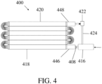
- This disclosure relates to conformable pressure vessel including pressure vessel segments defined by a cavity disposed within a liner.
- the pressure vessel segments receive and store a gas in a compressed state, and each of the pressure vessel segments includes a first section of the liner having a first diameter and a second section of the liner having a second diameter smaller than the first diameter.
- the conformable pressure vessel includes a reinforcement layer surrounding the liner and an inlet in fluid communication with the cavity of the liner. The inlet receives the gas from a gas source.
- the conformable pressure vessel further includes an outlet in fluid communication with the cavity of the liner, and the outlet outputs the gas from the pressure vessel segments.
- the conformable pressure vessel includes a connecting tube in fluid communication with the inlet and the outlet, and the connecting tube receives the gas from the outlet and to supply the gas from the outlet to the inlet so that the gas is recirculated through the pressure vessel segments in response to the inlet receiving the gas from the gas source.
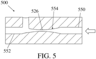
- the inlet may include a nozzle having a first end downstream of the gas source, a second end downstream of the first end and upstream of the pressure vessel segments, and a middle portion between the first end and the second end.
- the middle portion may have a cross-sectional area smaller than a cross-sectional area of the first end and a cross-sectional area of the second end. When the gas flows across the middle portion, the middle portion may increase velocity of gas flow as the gas source pushes the gas to the inlet.
- the connecting tube may include an entry end connected with the outlet and an exit end connected with the second end of the nozzle.
- a temperature of the conformable pressure vessel may be equalized.
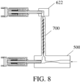
- An interior profile of the connecting tube may be shaped to enable flow of the gas through the connecting tube from the outlet to the inlet and to prevent the flow of the gas through the connecting tube from the inlet to the outlet.
- the connecting tube may include a tesla valve so that temperature of the conformable pressure vessel is equalized as the gas flows across the pressure vessel segments, the connecting tube, or both.
- the conformable pressure vessel may further include a shell enclosing the pressure vessel segments, and the inlet and the outlet may be integrated in walls of the shell so that the gas is movable between the pressure vessel segments and the outlet or the inlet.
- the conformable pressure vessel may further include heat pipes extending perpendicularly along the pressure vessel segments, and the heat pipes may allow heat to flow between the pressure vessel segments.
- the pressure vessel segments may be stacked within the shell in a row so that the heat pipes are laying across the pressure vessel segments.
- the conformable pressure vessel may further include thermally conductive materials surrounding the reinforcement layer at a top-most pressure vessel segment and a bottom-most pressure vessel segment, and the thermally conductive materials may assist creating an equilibrium of temperature between the pressure vessel segments.
- the inlet and the outlet each may include a stem creating a fluid connection between the pressure vessel segments and the connecting tube; and a cap securing the liner, the reinforcement layer, and the stem so that fluids are movable between the cavity and the inlet or the outlet.
- the disclosure further relates to a conformable pressure vessel including a liner defining a cavity and pressure vessel segments formed along the liner in first sections having a first diameter and second sections having a second diameter smaller than the first diameter.
- the conformable pressure vessel includes an inlet in fluid communication with the cavity of the liner through the second section of a first pressure vessel segment, and the inlet receives a gas from a gas source.
- the conformable pressure vessel includes an outlet in fluid communication with the cavity of the liner through the second section of a second pressure vessel segment, and the outlet outputs the gas from the liner.
- the conformable pressure vessel includes a connecting tube facilitating fluid communication between the inlet and the outlet so that the gas flows from the outlet to the inlet and is recirculated through the liner in a way that distributes heat throughout the pressure vessel segments, and the connecting tube receives the gas from the gas source.
- the conformable pressure vessel includes a reinforcement layer surrounding the liner and a phase change material coating an interior surface of the liner.
- the phase change material may coat every one of the pressure vessel segments so that the heat is distributed throughout the conformable pressure vessel.
- the phase change material may absorb energy and at least partially melt so that temperature of the conformable pressure vessel is equalized.
- the conformable pressure vessel may further include a nozzle having a first end connected with a middle portion and connect with the gas source and a second end connected with the middle portion and the connecting tube, and the middle portion may have a cross-sectional area smaller than a cross-sectional area of the first end and a cross-sectional area of the second end.
- the connecting tube may be connected with the outlet or the inlet, and when the connecting tube is connected with the outlet, the second end of the nozzle may space the connecting tube from the inlet. When the connecting tube is connected with the inlet, the second end of the nozzle may space the connecting tube from the outlet.
- the disclosure further relates to a conformable pressure vessel including pressure vessel segments, and each pressure vessel segment defines a cavity that is adjacent to a narrow portion.
- the pressure vessel segments couple together at the respective narrow portions so that the respective cavities are fluidly coupled and the pressure vessel segments form a continuous structure.
- the conformable pressure vessel includes an inlet in fluid communication with the cavities of the pressure vessel segments through the narrow portion of an entry pressure vessel segment, and the inlet receives a gas from a gas source.
- the conformable pressure vessel includes an outlet in fluid communication with the cavities of the pressure vessel segments through the narrow portion of an exit pressure vessel segment, and the outlet outputs the gas from the pressure vessel segments.
- the conformable pressure vessel includes heat pipes extending perpendicularly between stacked pressure vessel segments, and the heat pipes allow heat to flow between the pressure vessel segments.
- the conformable pressure vessel may further include a reinforcement layer positioned between the heat pipes and the pressure vessel segments, and the reinforcement layer may surround each of the pressure vessel segments.
- the conformable pressure vessel may further include a thermally conductive material surrounding the reinforcement layer and/or coupling two or more pressure vessel segments so that the heat pipes and the thermally conductive material distribute heat throughout the conformable pressure vessel.
- the conformable pressure vessel may further include a shell enclosing the thermally conductive material, the heat pipes, and the pressure vessel segments so that the thermally conductive material, the heat pipes, and the pressure vessel segments are protected from an outside environment.
- the heat pipes may extend from the entry pressure vessel segment to the exit pressure vessel segment so that each heat pipe contacts at least two pressure vessel segments.
- the thermal management methods disclosed herein are configured to manage the thermal gradient that arises due to pressurizing a conformable pressure vessel including pressure vessel segments.
- Heat gradients typically do not develop within the interior of traditional gas storage tanks because the gas is mixed throughout the entire storage tank instead of split between pressure vessel segments.
- the gas has the freedom to move and mix, so any rise in temperature is diffused evenly throughout the storage tank.
- traditional storage tanks are not sectioned, so there is no beginning or end.
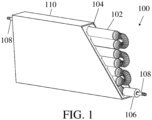
- a conformable pressure vessel includes seven pressure vessel segments.
- a last pressure vessel segment is capped with a plug and a first pressure vessel segment is connected to a valve to fill the conformable pressure vessel.
- Gas continuously enters the first pressure vessel segment and then gets pushed into the following pressure vessel segments as more gas enters.
- There is a pressure drop occurring in each consecutive pressure vessel segment because gas must flow through a section of each pressure vessel segment having a lesser diameter to reach the next pressure vessel segment. Therefore, the gas in the last pressure vessel segment is at a lower pressure than the gas in the first pressure vessel segment.
- Pressure tends to equalize throughout a traditional storage tank, but due to the pressure vessel segments included in the conformable pressure vessel, this equilibrium takes longer to achieve. Therefore, the pressure of the gas in the last pressure vessel segment will always lag behind the pressure of the gas in the first pressure vessel segment.
- a magnification of this phenomenon occurs when the fill rate of the conformable pressure vessel is increased. Adding gas at a faster rate causes the temperature difference between pressure vessel segments to be much greater and leads to heat building up within the conformable pressure vessel more quickly. This increase in heat within the conformable pressure vessel occurs because more gas molecules are compressed in a smaller amount of time.
- the first method involves using thermal conductive materials in the conformable pressure vessel.
- Thermal conductive materials leverage the increased surface to volume ratio of the pressure vessel to transfer heat between the different parts of the pressure vessel to achieve a thermal equilibrium and avoid extreme temperatures within the conformable pressure vessel.
- Another method recirculates the gases in the conformable pressure vessel.
- Another method uses phase change materials within the conformable pressure vessel.
- Thermally conductive material transfers heat from the pressure vessel segments having a higher temperature to the pressure vessel segments having a lower temperature due to heat transfer caused by conduction and convection.
- Each pressure vessel segment is defined by a liner material (e.g. a thermoplastic liner).
- a reinforcement layer surrounds the liner.
- the reinforcement layer can be surrounded by a thermally conductive material, such as a thermally conductive foam.
- a shell encloses the thermally conductive foam.
- Thermally conductive material such as a heat pipe, can couple two or more pressure vessel segments. Thermal conduction allows for more thermal consistency throughout the conformable pressure vessel, where heat transfer can reduce the temperature extremes and achieve faster thermal equilibrium.
- PCMs phase change material
- PCMs have been widely studied as thermal energy storage options in gas storage tanks. PCMs absorb heat generated during fueling of gas storage tanks in the form of latent heat. As the PCM absorbs heat, it begins to melt, but it does not heat up.
- the PCM includes paraffin wax embedded with a graphite matrix. The PCM works most efficiently when the mixture is applied to the inside of the liner. This configuration allows a faster fill rate of the conformable pressure vessel. The PCM also reduces the degree of pre-cooling required for a given fill time by 10 - 20°C.
- the end fittings connect the conformable pressure vessel 100 to valves, adapters, plugs, or couplings, and assist in containing the pressurized gas within the conformable pressure vessel 100.
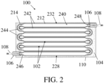
- FIG. 2 shows a sectional view of the same seven-segment conformable pressure vessel 100.
- Each pressure vessel segment 102 includes a liner 212 that defines a cavity 240.
- the liner 212 can include a thermoplastic liner.
- Each liner 212 includes a first section 242 having a first diameter and a second section 244 having a second diameter smaller than the first diameter.
- the pressure vessel segments 102 are coupled together at the respective second sections 244 of the liner 212 such that the cavities 240 of each liner 212 are fluidly coupled.
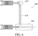
- the conformable pressure vessel 100 includes an inlet 246 in fluid communication with the cavities 240 of the pressure vessel segments 102 through the second section 244 of a first pressure vessel segment 228.
- the inlet 246 is configured to receive a gas from a gas source.
- the conformable pressure vessel 100 also includes an outlet 248 in fluid communication with the cavities 240 of the pressure vessel segments 102 through the second section 244 of a second pressure vessel segment 232.
- the outlet 248 is configured to output the gas from the pressure vessel segments 102. Though the outlet 248 is shown as being in fluid communication with the last pressure vessel segment in the seven-segment conformable pressure vessel 100 (i.e., the second pressure vessel segment 232) in this example, either the inlet 246 or the outlet 248 could be fluidly coupled with alternate pressure vessels segments.
- a reinforcement layer 214 surrounds the liner 212.
- the reinforcement layer 214 can include a fiber reinforcement layer.
- the thermally conductive foam 104 surrounds the reinforcement layer 214.
- the shell 110 encloses the thermally conductive foam 104 and the pressure vessel segments 102.
- One cap 106 connects to the liner 212 and the reinforcement layer 214 at the inlet 246.
- Another cap 106 connects to the liner 212 and the reinforcement layer 214 at the outlet 248.
- the caps 106 function to attach the stems 108 to the respective pressure vessel segments 102.
- the thermally conductive foam 104 and the shell 110 which provide structure, support, and protection for the pressure vessel segments 102, are also shown.
- thermally conductive materials such as thermally conductive foams and heat pipes as indicated herein, the high surface to volume ratio in conformable pressure vessels can be used to transfer heat from areas of high temperature to areas of low temperature. This can significantly reduce temperature extremes within the conformable pressure vessel. An example is described in reference to FIG. 3 .
- FIG. 3 is a side view of a six-segment pressure vessel 300.
- the pressure vessel 300 includes the pressure vessel segments 302.
- the pressure vessel segments 302 are connected by heat pipes 330, also referred to as thermally conductive members.
- the heat pipes 330 allow heat to flow between the pressure vessel segments 302. In this configuration, when different pressure vessel segments 302 are heated or cooled to different temperatures, the heat pipes 330 can assist in creating temperature equilibrium between the different pressure vessel segments 302.
- the heat pipes 330 are connected to thermally conductive materials 331 which are disposed around the top-most and bottom-most pressure vessel segments 302 in the example of FIG. 3 .
- the thermally conductive materials 331 can further assist in creating the temperature equilibrium between the pressure vessel segments 302.
- PCMs Phase change materials
- PCMs Phase change materials
- PCMs Phase change materials
- PCMs Phase change materials
- PCMs can store and release large amounts of latent heat energy.
- PCMs such as paraffin wax, can be used to coat an interior of the liner of the conformable pressure vessel. Then, as the coated pressure vessel segment is filled with gas and the temperature rises, the PCM will absorb the heat, preventing the temperature from rising. As the PCM absorbs heat, it begins to melt, but does not heat up.
- a PCM may coat an interior surface of the liner of one or more pressure vessel segments.
- the PCM may coat an interior surface of the liner of every pressure vessel segment individually or may coat the liner of only a first pressure vessel segment and a second (e.g. last) pressure vessel segment. Coating an interior surface of the liner of the first and last pressure vessel segments may assist to moderate the temperature of the conformable pressure vessel since the temperature is most extreme in these segments.
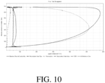
- FIG. 9 includes a graph of pressure vs. temperature curves for the first pressure vessel segment of different conformable pressure vessels including various temperature mitigation devices for the first 30 seconds of gas fill. Separate curves are shown to indicate performance of pressure vessels having the following features: a baseline pressure vessel including thermally conductive foam; a gas recirculating pressure vessel similar to that shown in FIG. 4 ; a heat pipe; a gas recirculating pressure vessel including a Tesla valve similar to that shown in FIG. 8 ; a pressure vessel including a phase change material (PCM); and a pressure vessel including all of these listed features.
- PCM phase change material
- Table 1 shows the minimum temperature of the first pressure vessel segment and the maximum temperature of the last pressure vessel segment of each conformable pressure vessel described with respect to FIGS. 9 and 10 .
- Table 1 Test Results of Conformable Pressure Vessels Using Different Thermal Mitigation Methods Thermal Mitigation Technique Minimum Temperature for First Segment (°C) Maximum Temperature for Last Segment(°C) Baseline Thermal Conductivity 15.7 582.0 Heat pipe 15.7 106.3 Simple Recirculation 15.7 515.0 Recirculation with Tesla valve 16.1 76.6 Phase Change Materials 17.0 43.8 All Techniques Together 18.9 110.2
- the recirculation method does allow the gases from the first and last pressure vessel segments to mix and provides some temperature mitigation; however, the recirculation method does not prevent the inflowing gas from initially traveling in the unintended direction from the first pressure vessel segment, through the connecting tube, and to the last pressure vessel segment. This extends the time required to establish a circulating flow path within the conformable pressure vessel.
- a PCM was used to coat the liner of the baseline conformable pressure vessel. As shown in FIG. 10 , the maximum temperature of the last pressure vessel segment was reduced to 43.8 °C. As shown in FIG. 9 , the minimum temperature of the first pressure vessel segment was increased to 17°C.
Landscapes
- Engineering & Computer Science (AREA)
- Mechanical Engineering (AREA)
- General Engineering & Computer Science (AREA)
- Filling Or Discharging Of Gas Storage Vessels (AREA)
Claims (15)
- Anpassbarer Druckbehälter (100, 300, 400, 600), Folgendes umfassend:Druckbehältersegmente (102), die durch einen Hohlraum (240) definiert sind, der in einer Auskleidung (212) angeordnet ist, wobei die Druckbehältersegmente (102) dazu ausgelegt sind, ein Gas aufzunehmen und in einem verdichteten Zustand zu lagern, und wobei jedes der Druckbehältersegmente (102) einen ersten Abschnitt (242) der Auskleidung (212) mit einem ersten Durchmesser und einen zweiten Abschnitt (244) der Auskleidung (212) mit einem zweiten Durchmesser, der kleiner ist als der erste Durchmesser, umfasst;eine Verstärkungsschicht (214), welche die Auskleidung (212) umgibt;einen Einlass (446), der mit dem Hohlraum (240) der Auskleidung (212) an einem ersten der Druckbehältersegmente (418) in Fluidverbindung steht und dazu ausgelegt ist, das Gas von einer Gasquelle zu empfangen, wobei der Einlass ein der Gasquelle nachgelagertes erstes Ende (550), ein dem ersten Ende (550) nachgelagertes zweites Ende (552) und einen Mittelteil (554) zwischen dem ersten Ende (550) und dem zweiten Ende (552) aufweist, wobei der Mittelteil (554) eine Querschnittsfläche aufweist, die kleiner ist als die Querschnittsfläche des ersten Endes (550) und die Querschnittsfläche des zweiten Endes (552); undeinen Auslass (448), der mit dem Hohlraum (240) der Auskleidung (212) an einem letzten der Druckbehältersegmente (420) in Fluidverbindung steht und dazu ausgelegt ist, das Gas aus den Druckbehältersegmenten (102) abzugeben, wobei der Auslass (448) dazu ausgelegt ist, mit dem zweiten Ende (552) des Einlasses (446) durch ein Verbindungsrohr (424) in Fluidverbindung zu stehen, das ein Innenprofil aufweist, das dazu geformt ist, die Strömung des Gases durch das Verbindungsrohr (424) vom Auslass (448) zum Einlass (446) zuzulassen und die Strömung des Gases durch das Verbindungsrohr (424) vom Einlass (446) zum Auslass (448) zu verhindern;wobei, wenn das Gas über den Mittelteil (554) des Einlasses (446) strömt, die Geschwindigkeit der Gasströmung zunimmt, um einen Niederdruckbereich im Einlass (446) zu erzeugen,wobei der Niederdruckbereich im Einlass (446) und das Innenprofil des Verbindungsrohrs (424) dazu ausgelegt sind, die Strömung vom letzten der Druckbehältersegmente (420) zum ersten der Druckbehältersegmente (418) anzuregen, um das Gas als Reaktion darauf, dass der Einlass (446) das Gas von der Gasquelle erhält, durch die Druckbehältersegmente (102) umzuwälzen, undwobei das Umwälzen des Gases durch die Druckbehältersegmente (102) die Temperatur des anpassbaren Druckbehälters (100, 300, 400, 600) ausgleicht.
- Anpassbarer Druckbehälter (100, 300, 400, 600) nach Anspruch 1, wobei das Verbindungsrohr (424) ein Eingangsende, das dazu ausgelegt ist, mit dem Auslass (448) verbunden zu sein, und ein Ausgangsende, das dazu ausgelegt ist, mit dem zweiten Ende des Einlasses (446) verbunden zu sein, umfasst und wobei das Verbindungsrohr (424) dazu ausgelegt ist, das Gas vom Auslass (448) aufzunehmen und das Gas vom Auslass (448) zum Einlass (446) zuzuführen.
- Anpassbarer Druckbehälter (100, 300, 400, 600) nach Anspruch 1 oder 2, wobei das Innenprofil des Verbindungsrohrs (424) ein Teslaventil (700) umfasst.
- Anpassbarer Druckbehälter (100, 300, 400, 600) nach einem der Ansprüche 1 bis 3, ferner umfassend:
ein Phasenwechselmaterial (PCM), mit dem eine Innenfläche der Auskleidung (212) beschichtet ist und das dazu ausgelegt ist, Energie zu absorbieren und zumindest teilweise zu schmelzen, um die Temperatur des anpassbaren Druckbehälters (100, 300, 400, 600) auszugleichen. - Anpassbarer Druckbehälter (100, 300, 400, 600) nach Anspruch 4, wobei das Phasenwechselmaterial (PCM) die Innenfläche der Auskleidung (212) des ersten der Druckbehältersegmente (420) und des letzten der Druckbehältersegmente (418) beschichtet.
- Anpassbarer Druckbehälter (100, 300, 400, 600) nach Anspruch 4, wobei das Phasenwechselmaterial (PCM) die Innenfläche der Auskleidung (212) aller Druckbehältersegmente (102) beschichtet.
- Anpassbarer Druckbehälter (100, 300, 400, 600) nach einem der Ansprüche 1 bis 6, ferner umfassend:einen Mantel (110), der die Druckbehältersegmente (102) umschließt,wobei der Einlass (446) und der Auslass (448) in Wände des Mantels (110) integriert sind, sodass das Gas zwischen den Druckbehältersegmenten (102) und dem Auslass (448) oder dem Einlass (446) beweglich ist.
- Anpassbarer Druckbehälter (100, 300, 400, 600) nach Anspruch 7, ferner umfassend:Wärmerohre (330), die sich senkrecht entlang der Druckbehältersegmente (302) erstrecken, wobei die Wärmerohre (330) dazu ausgelegt sind, zuzulassen, dass Wärme zwischen den Druckbehältersegmenten (302) strömt,wobei die Druckbehältersegmente (302) innerhalb des Mantels (110) in einer Reihe gestapelt sind, sodass die Wärmerohre (330) über den Druckbehältersegmenten (302) liegen.
- Anpassbarer Druckbehälter (100, 300, 400, 600) nach einem der Ansprüche 1 bis 8, ferner umfassend:
ein wärmeleitfähiges Material, das die Verstärkungsschicht (214) am ersten der Druckbehältersegmente (420) und am letzten der Druckbehältersegmente (418) umgibt, wobei das wärmeleitfähige Material dazu ausgelegt ist, zum Erzeugen eines Temperaturgleichgewichts zwischen den Druckbehältersegmenten (102) beizutragen. - Anpassbarer Druckbehälter (100, 300, 400, 600) nach einem der Ansprüche 1 bis 8, ferner umfassend:
ein wärmeleitfähiges Material, das die Verstärkungsschicht (214) an allen Druckbehältersegmenten (102) umgibt, wobei das wärmeleitfähige Material dazu ausgelegt ist, zum Erzeugen eines Temperaturgleichgewichts zwischen den Druckbehältersegmenten (102) beizutragen. - Anpassbarer Druckbehälter (100, 300, 400, 600) nach Anspruch 9 oder 10, wobei das wärmeleitfähige Material ein wärmeleitfähiger Schaumstoff (104) ist.
- Anpassbarer Druckbehälter (100, 300, 400, 600) nach Anspruch 11, ferner umfassend:
einen Mantel (110), der die Druckbehältersegmente (102) und den wärmeleitfähigen Schaumstoff (104) umschließt. - Anpassbarer Druckbehälter (100, 300, 400, 600) nach einem der Ansprüche 1 bis 12, wobei der Einlass (446) und der Auslass (448) jeweils Folgendes umfassen:einen Fuß (108, 408), der eine Fluidverbindung zwischen den Druckbehältersegmenten (102) und dem Verbindungsrohr (424) erzeugt; undeine Kappe (106), welche die Auskleidung (212), die Verstärkungsschicht (214) und den Fuß (108, 408) fixiert, sodass Fluide zwischen dem Hohlraum (240) und dem Einlass (446) oder dem Auslass (448) beweglich sind.
- Anpassbarer Druckbehälter (100, 300, 400, 600) nach einem der Ansprüche 1 bis 13, wobei der Einlass (446) mit dem Hohlraum (240) der Auskleidung (212) am ersten der Druckbehältersegmente (420) durch den zweiten Abschnitt (244) der Auskleidung (212) des ersten der Druckbehältersegmente (420) in Fluidverbindung steht.
- Anpassbarer Druckbehälter (100, 300, 400, 600) nach einem der Ansprüche 1 bis 14, wobei der Auslass (448) mit dem Hohlraum (240) der Auskleidung (212) am letzten der Druckbehältersegmente (418) durch den zweiten Abschnitt (244) der Auskleidung (212) des letzten der Druckbehältersegmente (418) in Fluidverbindung steht.
Applications Claiming Priority (2)
| Application Number | Priority Date | Filing Date | Title |
|---|---|---|---|
| US201962900940P | 2019-09-16 | 2019-09-16 | |
| PCT/US2020/050816 WO2021055319A1 (en) | 2019-09-16 | 2020-09-15 | Thermal management in conformable tanks |
Publications (3)
| Publication Number | Publication Date |
|---|---|
| EP4031796A1 EP4031796A1 (de) | 2022-07-27 |
| EP4031796A4 EP4031796A4 (de) | 2023-10-04 |
| EP4031796B1 true EP4031796B1 (de) | 2025-07-09 |
Family
ID=74883243
Family Applications (1)
| Application Number | Title | Priority Date | Filing Date |
|---|---|---|---|
| EP20865724.7A Active EP4031796B1 (de) | 2019-09-16 | 2020-09-15 | Wärmemanagement in anpassbaren tanks |
Country Status (3)
| Country | Link |
|---|---|
| US (1) | US12259090B2 (de) |
| EP (1) | EP4031796B1 (de) |
| WO (1) | WO2021055319A1 (de) |
Families Citing this family (2)
| Publication number | Priority date | Publication date | Assignee | Title |
|---|---|---|---|---|
| CA3241872A1 (en) | 2021-12-06 | 2023-06-15 | Linamar Corporation | On tank manifold valve assembly |
| GB2637552A (en) * | 2024-01-29 | 2025-07-30 | Phinia Delphi Luxembourg Sarl | Hydrogen tank |
Family Cites Families (10)
| Publication number | Priority date | Publication date | Assignee | Title |
|---|---|---|---|---|
| RU16671U1 (ru) | 2000-03-31 | 2001-01-27 | Московский государственный авиационный институт (технический университет) | Сосуд высокого давления |
| DE102004017392A1 (de) | 2004-04-08 | 2005-10-27 | Bayerische Motoren Werke Ag | Druckbehälter zur Speicherung von kryogenen Kraftstoffen |
| WO2014123928A1 (en) * | 2013-02-05 | 2014-08-14 | Other Lab, Llc | Natural gas intestine packed storage tank |
| CN106574108B (zh) * | 2014-08-20 | 2018-11-06 | 沙特基础工业全球技术有限公司 | 热塑性组合物、它们的制备方法及其制品 |
| CN107923572A (zh) * | 2015-06-15 | 2018-04-17 | 奥特尔实验室有限责任公司 | 用于可保形压力容器的系统和方法 |
| JP2019507850A (ja) * | 2015-12-02 | 2019-03-22 | アザー ラブ リミテッド ライアビリティ カンパニー | ライナーを編組するため及び樹脂を塗布するためのシステム及び方法 |
| US10337671B2 (en) * | 2016-09-16 | 2019-07-02 | GM Global Technology Operations LLC | Innovative thermal management approaches of conformable tanks |
| WO2018183767A1 (en) * | 2017-03-31 | 2018-10-04 | Other Lab, Llc | Tank filling system and method |
| US20180283610A1 (en) * | 2017-03-31 | 2018-10-04 | Other Lab, Llc | Tank enclosure and tank mount system and method |
| DE102018010103A1 (de) * | 2018-12-21 | 2019-07-18 | Daimler Ag | Ringtank |
-
2020
- 2020-09-15 EP EP20865724.7A patent/EP4031796B1/de active Active
- 2020-09-15 US US17/760,647 patent/US12259090B2/en active Active
- 2020-09-15 WO PCT/US2020/050816 patent/WO2021055319A1/en not_active Ceased
Also Published As
| Publication number | Publication date |
|---|---|
| US12259090B2 (en) | 2025-03-25 |
| EP4031796A1 (de) | 2022-07-27 |
| WO2021055319A1 (en) | 2021-03-25 |
| EP4031796A4 (de) | 2023-10-04 |
| US20220333739A1 (en) | 2022-10-20 |
Similar Documents
| Publication | Publication Date | Title |
|---|---|---|
| EP4031796B1 (de) | Wärmemanagement in anpassbaren tanks | |
| CN106595759B (zh) | 一种低温推进剂贮存技术地面试验系统 | |
| Lui et al. | Spatial structure of the thermal boundary layer in turbulent convection | |
| JP7370384B2 (ja) | 非石油燃料の温度を制御するための流体バイパス方法及びシステム | |
| Hartwig et al. | Comparison of cryogenic flow boiling in liquid nitrogen and liquid hydrogen chilldown experiments | |
| US10845005B2 (en) | Tank filling system and method | |
| Wang et al. | Research on the cooling performance of the discontinuous transpiration surface structure for the leading edge of a hypersonic vehicle | |
| CN112084722B (zh) | 一种快速计算短舱冷却空气流量和壁面温度分布的方法 | |
| Leontiev et al. | Effect of gaseous coolant temperature on the transpiration cooling for porous wall in the supersonic flow | |
| Hartwig et al. | A steady state pressure drop model for screen channel liquid acquisition devices | |
| Wadel | Comparison of high aspect ratio cooling channel designs for a rocket combustion chamber with development of an optimized design | |
| Steward et al. | Cooldown transients in cryogenic transfer lines | |
| Landis et al. | Numerical study of a transpiration cooled rocket nozzle | |
| Yu et al. | Flow and heat transfer of supercritical RP-3 kerosene in an inclined rectangular channel heated on one side | |
| EP0254778A1 (de) | Verteilungssystem von flüssigem Stickstoff | |
| Iwata et al. | Temperature-controllable oscillating heat pipe | |
| Naraghi et al. | Dual regenerative cooling circuits for liquid rocket engines | |
| Qiu et al. | Experimental investigation on the temperature and pressure characteristics of supercritical helium for liquid hydrogen pressurisation | |
| Naraghi et al. | Modeling of radiation heat transfer in liquid rocket engines | |
| Napolitano et al. | Effects of variable transport properties on thermal Marangoni flows | |
| Mukka et al. | Analysis of fluid flow and heat transfer in a liquid hydrogen storage vessel for space applications | |
| Bouquet et al. | Fully ceramic composite heat exchanger qualification for advanced combustion chambers | |
| Zhang et al. | Experimental evaluation and modeling of passive thermodynamic vent system in a small liquid nitrogen tank | |
| FAZAH et al. | Design and integrated operation of an innovative thermodynamic vent system concept | |
| Antoniuk et al. | Development of an oxygen axial groove heatpipe for a microgravity flight experiment |
Legal Events
| Date | Code | Title | Description |
|---|---|---|---|
| STAA | Information on the status of an ep patent application or granted ep patent |
Free format text: STATUS: THE INTERNATIONAL PUBLICATION HAS BEEN MADE |
|
| PUAI | Public reference made under article 153(3) epc to a published international application that has entered the european phase |
Free format text: ORIGINAL CODE: 0009012 |
|
| STAA | Information on the status of an ep patent application or granted ep patent |
Free format text: STATUS: REQUEST FOR EXAMINATION WAS MADE |
|
| 17P | Request for examination filed |
Effective date: 20220412 |
|
| AK | Designated contracting states |
Kind code of ref document: A1 Designated state(s): AL AT BE BG CH CY CZ DE DK EE ES FI FR GB GR HR HU IE IS IT LI LT LU LV MC MK MT NL NO PL PT RO RS SE SI SK SM TR |
|
| DAV | Request for validation of the european patent (deleted) | ||
| DAX | Request for extension of the european patent (deleted) | ||
| A4 | Supplementary search report drawn up and despatched |
Effective date: 20230905 |
|
| RIC1 | Information provided on ipc code assigned before grant |
Ipc: F17C 13/10 20060101ALI20230830BHEP Ipc: F17C 5/06 20060101ALI20230830BHEP Ipc: F17C 1/12 20060101AFI20230830BHEP |
|
| GRAP | Despatch of communication of intention to grant a patent |
Free format text: ORIGINAL CODE: EPIDOSNIGR1 |
|
| STAA | Information on the status of an ep patent application or granted ep patent |
Free format text: STATUS: GRANT OF PATENT IS INTENDED |
|
| INTG | Intention to grant announced |
Effective date: 20250213 |
|
| GRAS | Grant fee paid |
Free format text: ORIGINAL CODE: EPIDOSNIGR3 |
|
| GRAA | (expected) grant |
Free format text: ORIGINAL CODE: 0009210 |
|
| STAA | Information on the status of an ep patent application or granted ep patent |
Free format text: STATUS: THE PATENT HAS BEEN GRANTED |
|
| AK | Designated contracting states |
Kind code of ref document: B1 Designated state(s): AL AT BE BG CH CY CZ DE DK EE ES FI FR GB GR HR HU IE IS IT LI LT LU LV MC MK MT NL NO PL PT RO RS SE SI SK SM TR |
|
| REG | Reference to a national code |
Ref country code: GB Ref legal event code: FG4D |
|
| REG | Reference to a national code |
Ref country code: CH Ref legal event code: EP |
|
| REG | Reference to a national code |
Ref country code: IE Ref legal event code: FG4D |
|
| REG | Reference to a national code |
Ref country code: DE Ref legal event code: R096 Ref document number: 602020054356 Country of ref document: DE |
|
| PGFP | Annual fee paid to national office [announced via postgrant information from national office to epo] |
Ref country code: DE Payment date: 20250929 Year of fee payment: 6 |
|
| PGFP | Annual fee paid to national office [announced via postgrant information from national office to epo] |
Ref country code: GB Payment date: 20250929 Year of fee payment: 6 |
|
| PGFP | Annual fee paid to national office [announced via postgrant information from national office to epo] |
Ref country code: FR Payment date: 20250925 Year of fee payment: 6 |
|
| REG | Reference to a national code |
Ref country code: CH Ref legal event code: W10 Free format text: ST27 STATUS EVENT CODE: U-0-0-W10-W00 (AS PROVIDED BY THE NATIONAL OFFICE) Effective date: 20251022 |
|
| REG | Reference to a national code |
Ref country code: NL Ref legal event code: MP Effective date: 20250709 |
|
| RAP4 | Party data changed (patent owner data changed or rights of a patent transferred) |
Owner name: NOBLE GAS SYSTEMS, INC. |
|
| PG25 | Lapsed in a contracting state [announced via postgrant information from national office to epo] |
Ref country code: PT Free format text: LAPSE BECAUSE OF FAILURE TO SUBMIT A TRANSLATION OF THE DESCRIPTION OR TO PAY THE FEE WITHIN THE PRESCRIBED TIME-LIMIT Effective date: 20251110 |
|
| PG25 | Lapsed in a contracting state [announced via postgrant information from national office to epo] |
Ref country code: NL Free format text: LAPSE BECAUSE OF FAILURE TO SUBMIT A TRANSLATION OF THE DESCRIPTION OR TO PAY THE FEE WITHIN THE PRESCRIBED TIME-LIMIT Effective date: 20250709 |
|
| REG | Reference to a national code |
Ref country code: AT Ref legal event code: MK05 Ref document number: 1812090 Country of ref document: AT Kind code of ref document: T Effective date: 20250709 |
|
| PG25 | Lapsed in a contracting state [announced via postgrant information from national office to epo] |
Ref country code: IS Free format text: LAPSE BECAUSE OF FAILURE TO SUBMIT A TRANSLATION OF THE DESCRIPTION OR TO PAY THE FEE WITHIN THE PRESCRIBED TIME-LIMIT Effective date: 20251109 |
|
| PG25 | Lapsed in a contracting state [announced via postgrant information from national office to epo] |
Ref country code: NO Free format text: LAPSE BECAUSE OF FAILURE TO SUBMIT A TRANSLATION OF THE DESCRIPTION OR TO PAY THE FEE WITHIN THE PRESCRIBED TIME-LIMIT Effective date: 20251009 |
|
| REG | Reference to a national code |
Ref country code: LT Ref legal event code: MG9D |
|
| PG25 | Lapsed in a contracting state [announced via postgrant information from national office to epo] |
Ref country code: AT Free format text: LAPSE BECAUSE OF FAILURE TO SUBMIT A TRANSLATION OF THE DESCRIPTION OR TO PAY THE FEE WITHIN THE PRESCRIBED TIME-LIMIT Effective date: 20250709 |
|
| PG25 | Lapsed in a contracting state [announced via postgrant information from national office to epo] |
Ref country code: FI Free format text: LAPSE BECAUSE OF FAILURE TO SUBMIT A TRANSLATION OF THE DESCRIPTION OR TO PAY THE FEE WITHIN THE PRESCRIBED TIME-LIMIT Effective date: 20250709 |
|
| PG25 | Lapsed in a contracting state [announced via postgrant information from national office to epo] |
Ref country code: HR Free format text: LAPSE BECAUSE OF FAILURE TO SUBMIT A TRANSLATION OF THE DESCRIPTION OR TO PAY THE FEE WITHIN THE PRESCRIBED TIME-LIMIT Effective date: 20250709 |
|
| PG25 | Lapsed in a contracting state [announced via postgrant information from national office to epo] |
Ref country code: GR Free format text: LAPSE BECAUSE OF FAILURE TO SUBMIT A TRANSLATION OF THE DESCRIPTION OR TO PAY THE FEE WITHIN THE PRESCRIBED TIME-LIMIT Effective date: 20251010 |
|
| PG25 | Lapsed in a contracting state [announced via postgrant information from national office to epo] |
Ref country code: SE Free format text: LAPSE BECAUSE OF FAILURE TO SUBMIT A TRANSLATION OF THE DESCRIPTION OR TO PAY THE FEE WITHIN THE PRESCRIBED TIME-LIMIT Effective date: 20250709 |
|
| PG25 | Lapsed in a contracting state [announced via postgrant information from national office to epo] |
Ref country code: LV Free format text: LAPSE BECAUSE OF FAILURE TO SUBMIT A TRANSLATION OF THE DESCRIPTION OR TO PAY THE FEE WITHIN THE PRESCRIBED TIME-LIMIT Effective date: 20250709 |
|
| PG25 | Lapsed in a contracting state [announced via postgrant information from national office to epo] |
Ref country code: BG Free format text: LAPSE BECAUSE OF FAILURE TO SUBMIT A TRANSLATION OF THE DESCRIPTION OR TO PAY THE FEE WITHIN THE PRESCRIBED TIME-LIMIT Effective date: 20250709 Ref country code: PL Free format text: LAPSE BECAUSE OF FAILURE TO SUBMIT A TRANSLATION OF THE DESCRIPTION OR TO PAY THE FEE WITHIN THE PRESCRIBED TIME-LIMIT Effective date: 20250709 |
|
| PG25 | Lapsed in a contracting state [announced via postgrant information from national office to epo] |
Ref country code: RS Free format text: LAPSE BECAUSE OF FAILURE TO SUBMIT A TRANSLATION OF THE DESCRIPTION OR TO PAY THE FEE WITHIN THE PRESCRIBED TIME-LIMIT Effective date: 20251009 |
|
| PG25 | Lapsed in a contracting state [announced via postgrant information from national office to epo] |
Ref country code: ES Free format text: LAPSE BECAUSE OF FAILURE TO SUBMIT A TRANSLATION OF THE DESCRIPTION OR TO PAY THE FEE WITHIN THE PRESCRIBED TIME-LIMIT Effective date: 20250709 |