EP4031761B1 - Système de démarrage à froid pour un véhicule fonctionnant au moyen de gaz comprimé et présentant une alimentation en carburant de type monocarburation - Google Patents
Système de démarrage à froid pour un véhicule fonctionnant au moyen de gaz comprimé et présentant une alimentation en carburant de type monocarburation Download PDFInfo
- Publication number
- EP4031761B1 EP4031761B1 EP20781309.8A EP20781309A EP4031761B1 EP 4031761 B1 EP4031761 B1 EP 4031761B1 EP 20781309 A EP20781309 A EP 20781309A EP 4031761 B1 EP4031761 B1 EP 4031761B1
- Authority
- EP
- European Patent Office
- Prior art keywords
- circuit
- internal combustion
- combustion engine
- heating circuit
- interior
- Prior art date
- Legal status (The legal status is an assumption and is not a legal conclusion. Google has not performed a legal analysis and makes no representation as to the accuracy of the status listed.)
- Active
Links
- 239000000446 fuel Substances 0.000 title description 19
- 238000010438 heat treatment Methods 0.000 claims description 130
- 238000002485 combustion reaction Methods 0.000 claims description 91
- 238000001816 cooling Methods 0.000 claims description 55
- 239000012530 fluid Substances 0.000 claims description 23
- 239000000498 cooling water Substances 0.000 claims description 6
- 230000001419 dependent effect Effects 0.000 claims description 5
- 238000007710 freezing Methods 0.000 description 9
- 230000008014 freezing Effects 0.000 description 9
- 238000005086 pumping Methods 0.000 description 7
- 238000000034 method Methods 0.000 description 3
- 238000002347 injection Methods 0.000 description 2
- 239000007924 injection Substances 0.000 description 2
- 238000010792 warming Methods 0.000 description 2
- 230000003213 activating effect Effects 0.000 description 1
- 238000007664 blowing Methods 0.000 description 1
- 238000006243 chemical reaction Methods 0.000 description 1
- 238000005352 clarification Methods 0.000 description 1
- 230000006835 compression Effects 0.000 description 1
- 238000007906 compression Methods 0.000 description 1
- 239000002826 coolant Substances 0.000 description 1
- 230000008878 coupling Effects 0.000 description 1
- 238000010168 coupling process Methods 0.000 description 1
- 238000005859 coupling reaction Methods 0.000 description 1
- 230000000694 effects Effects 0.000 description 1
- 230000010354 integration Effects 0.000 description 1
- 210000002023 somite Anatomy 0.000 description 1
- 238000011144 upstream manufacturing Methods 0.000 description 1
Images


Classifications
-
- F—MECHANICAL ENGINEERING; LIGHTING; HEATING; WEAPONS; BLASTING
- F02—COMBUSTION ENGINES; HOT-GAS OR COMBUSTION-PRODUCT ENGINE PLANTS
- F02M—SUPPLYING COMBUSTION ENGINES IN GENERAL WITH COMBUSTIBLE MIXTURES OR CONSTITUENTS THEREOF
- F02M21/00—Apparatus for supplying engines with non-liquid fuels, e.g. gaseous fuels stored in liquid form
- F02M21/02—Apparatus for supplying engines with non-liquid fuels, e.g. gaseous fuels stored in liquid form for gaseous fuels
- F02M21/06—Apparatus for de-liquefying, e.g. by heating
-
- B—PERFORMING OPERATIONS; TRANSPORTING
- B60—VEHICLES IN GENERAL
- B60H—ARRANGEMENTS OF HEATING, COOLING, VENTILATING OR OTHER AIR-TREATING DEVICES SPECIALLY ADAPTED FOR PASSENGER OR GOODS SPACES OF VEHICLES
- B60H1/00—Heating, cooling or ventilating [HVAC] devices
- B60H1/22—Heating, cooling or ventilating [HVAC] devices the heat being derived otherwise than from the propulsion plant
- B60H1/2203—Heating, cooling or ventilating [HVAC] devices the heat being derived otherwise than from the propulsion plant the heat being derived from burners
- B60H1/2209—Heating, cooling or ventilating [HVAC] devices the heat being derived otherwise than from the propulsion plant the heat being derived from burners arrangements of burners for heating an intermediate liquid
-
- F—MECHANICAL ENGINEERING; LIGHTING; HEATING; WEAPONS; BLASTING
- F01—MACHINES OR ENGINES IN GENERAL; ENGINE PLANTS IN GENERAL; STEAM ENGINES
- F01P—COOLING OF MACHINES OR ENGINES IN GENERAL; COOLING OF INTERNAL-COMBUSTION ENGINES
- F01P11/00—Component parts, details, or accessories not provided for in, or of interest apart from, groups F01P1/00 - F01P9/00
- F01P11/14—Indicating devices; Other safety devices
- F01P11/20—Indicating devices; Other safety devices concerning atmospheric freezing conditions, e.g. automatically draining or heating during frosty weather
-
- F—MECHANICAL ENGINEERING; LIGHTING; HEATING; WEAPONS; BLASTING
- F02—COMBUSTION ENGINES; HOT-GAS OR COMBUSTION-PRODUCT ENGINE PLANTS
- F02M—SUPPLYING COMBUSTION ENGINES IN GENERAL WITH COMBUSTIBLE MIXTURES OR CONSTITUENTS THEREOF
- F02M21/00—Apparatus for supplying engines with non-liquid fuels, e.g. gaseous fuels stored in liquid form
- F02M21/02—Apparatus for supplying engines with non-liquid fuels, e.g. gaseous fuels stored in liquid form for gaseous fuels
- F02M21/0218—Details on the gaseous fuel supply system, e.g. tanks, valves, pipes, pumps, rails, injectors or mixers
- F02M21/023—Valves; Pressure or flow regulators in the fuel supply or return system
- F02M21/0239—Pressure or flow regulators therefor
-
- B—PERFORMING OPERATIONS; TRANSPORTING
- B60—VEHICLES IN GENERAL
- B60H—ARRANGEMENTS OF HEATING, COOLING, VENTILATING OR OTHER AIR-TREATING DEVICES SPECIALLY ADAPTED FOR PASSENGER OR GOODS SPACES OF VEHICLES
- B60H1/00—Heating, cooling or ventilating [HVAC] devices
- B60H1/22—Heating, cooling or ventilating [HVAC] devices the heat being derived otherwise than from the propulsion plant
- B60H2001/2228—Heating, cooling or ventilating [HVAC] devices the heat being derived otherwise than from the propulsion plant controlling the operation of heaters
- B60H2001/2234—Heating, cooling or ventilating [HVAC] devices the heat being derived otherwise than from the propulsion plant controlling the operation of heaters when vehicle is parked, preheating
-
- F—MECHANICAL ENGINEERING; LIGHTING; HEATING; WEAPONS; BLASTING
- F01—MACHINES OR ENGINES IN GENERAL; ENGINE PLANTS IN GENERAL; STEAM ENGINES
- F01P—COOLING OF MACHINES OR ENGINES IN GENERAL; COOLING OF INTERNAL-COMBUSTION ENGINES
- F01P2060/00—Cooling circuits using auxiliaries
- F01P2060/18—Heater
-
- F—MECHANICAL ENGINEERING; LIGHTING; HEATING; WEAPONS; BLASTING
- F02—COMBUSTION ENGINES; HOT-GAS OR COMBUSTION-PRODUCT ENGINE PLANTS
- F02N—STARTING OF COMBUSTION ENGINES; STARTING AIDS FOR SUCH ENGINES, NOT OTHERWISE PROVIDED FOR
- F02N19/00—Starting aids for combustion engines, not otherwise provided for
- F02N19/02—Aiding engine start by thermal means, e.g. using lighted wicks
- F02N19/04—Aiding engine start by thermal means, e.g. using lighted wicks by heating of fluids used in engines
-
- Y—GENERAL TAGGING OF NEW TECHNOLOGICAL DEVELOPMENTS; GENERAL TAGGING OF CROSS-SECTIONAL TECHNOLOGIES SPANNING OVER SEVERAL SECTIONS OF THE IPC; TECHNICAL SUBJECTS COVERED BY FORMER USPC CROSS-REFERENCE ART COLLECTIONS [XRACs] AND DIGESTS
- Y02—TECHNOLOGIES OR APPLICATIONS FOR MITIGATION OR ADAPTATION AGAINST CLIMATE CHANGE
- Y02T—CLIMATE CHANGE MITIGATION TECHNOLOGIES RELATED TO TRANSPORTATION
- Y02T10/00—Road transport of goods or passengers
- Y02T10/10—Internal combustion engine [ICE] based vehicles
- Y02T10/30—Use of alternative fuels, e.g. biofuels
Definitions
- the invention relates to a cold start system and an associated method for a compressed gas-powered vehicle with a monovalent fuel supply.
- the state of the art is defined as the publications EN 10 2008 034 581 A1 , DE 10 2014 218 632 A1 and EN 10 2014 219 500 A1
- the closest state of the art is the DE 10 2014 218 632 A1 which describes a device for supplying fuel to a vehicle powered by compressed gas, which has a pressure reduction device for reducing a fuel pressure from a tank pressure to a supply pressure of a fuel injection device, wherein the pressure reduction device has a housing, wherein an expansion region is formed within the housing, in which compressed gas is expanded, the housing has a region formed as a heating region, in which a heating device for heating the housing is arranged, and at least one control device of the heating device is provided for controlling the heating.
- the heating is controlled by means of a control unit including software. Either electrical heating elements or the flow of cooling water or a combination are described as heating.
- the invention is based on the object of creating a cold start system for a fuel supply system of an internal combustion engine, in which icing of components of the fuel supply system is avoided in the most efficient way possible.
- first and fifth operating mode can be operated depending on the OFF/ON operating state of the internal combustion engine, whereby the operating modes are explained in more detail in the description.
- the cold start system according to the invention has preferred extensions of the basic variant, which make it possible to use additional operating modes.
- second and sixth operating modes can be operated depending on the OFF/ON operating state of the internal combustion engine, whereby in these operating modes several components to be heated can be heated by means of the auxiliary heating unit, whereby the operating modes are explained in more detail in the description.
- different operating modes (a third and seventh operating mode as well as a fourth and eighth operating mode) can be operated depending on the operating state OFF/ON of the internal combustion engine, whereby in these operating modes several components to be heated and the cooling circuit can be heated by means of the auxiliary heating unit, whereby the operating modes are also explained in more detail in the description.
- the cold start system 100 comprises an internal combustion engine 10 with a conventional cooling system, which is symbolized in the figures as cooling module 11.
- the known cooling circuit leading from the cooling module is shown in the Figures 1 to 8 not explicitly shown.
- the internal combustion engine 10 is operated exclusively with compressed gas, that is, the internal combustion engine 10 is assigned a monovalent fuel supply.
- the cooling module 11 has an interior heating circuit 10VL, 10RL branching off from the cooling module 11, which serves to heat a vehicle interior by means of an interior heater 40.
- the heat generated in the internal combustion engine 100 is transferred to the vehicle interior by means of a fluid via corresponding heat exchangers (not shown) in the area of the interior heating 40 and in the area of the cooling module 11 via the interior heating circuit 10VL, 10RL.
- An interior heating circuit flow is marked with the reference symbol 10VL.
- An interior heating circuit return is marked with the reference symbol 10RL.
- a first valve 1 is arranged in the interior heating circuit flow 10VL.
- a second valve 2 is arranged in the interior heating circuit return 10RL.
- a parking heater flow 20VL of a parking heater preheating circuit 20VL, 20RL and a gas pressure regulator 30 with a gas pressure regulator heating circuit flow 30 VL of a gas pressure regulator heating circuit 30VL, 30RL are integrated in front of the first valve 1.
- Heat from the cold start system 100 is supplied to the gas pressure regulator 30 via the gas pressure regulator heating circuit flow 30 VL and transferred to the gas pressure regulator 30 via a heat exchanger (not shown).
- the auxiliary heating unit is marked with the reference number 20.
- the auxiliary heating unit 20 is operated with compressed gas, i.e. the auxiliary heating unit 20 uses the fuel that is also used for the internal combustion engine 10, so that the vehicle does not require an additional fuel supply system for supplying a different fuel.
- the invention is designed so that both the auxiliary heating unit 20 and the internal combustion engine 10 can be operated monovalently with the same fuel, which is seen as a significant advantage of the cold start system 100.
- the auxiliary heating unit 20 has a heat exchanger (also not shown) by means of which the heat is transferred to the fluid in the cold start system 100.
- a parking heater preheating circuit flow is identified with the reference symbol 20VL.
- a parking heater preheating circuit return is identified with the reference symbol 20RL.
- a preheating circuit pump 21 is arranged in the auxiliary heating preheating circuit flow 20VL, which pumps the fluid via the auxiliary heating preheating circuit flow 20VL into the interior heating circuit flow 10VL.
- the gas pressure regulator heating circuit flow 30VL of the gas pressure regulator heating circuit 30VL, 30RL branches off from the interior heating circuit flow VL, whereby the auxiliary heating preheating circuit flow 20VL and the gas pressure regulator heating circuit flow 30VL are integrated into the interior heating circuit flow VL one after the other between the cooling module 11 and the first valve 1, as seen in the flow direction of the fluid.
- the interior heating circuit return 10RL between the interior heater 40 and the cooling module 11 comprises the second valve 2, in front of which a gas pressure regulator heating circuit return 30RL and an auxiliary heating preheating circuit return 20RL branch off to the gas pressure regulator 30 and to the auxiliary heating unit 20.
- the Figures 1 to 8 thus show a piping or hose plan between the cooling module 11 of the internal combustion engine 10, a parking heater unit 20 at least a component to be heated, a gas pressure regulator 30 and a further component to be heated, an interior heater 40, and optionally the cooling circuit of the internal combustion engine 10 itself, as further components to be heated, wherein a pump 21 which is adjustable in terms of volume flow is arranged, which pumps the fluid in an operating mode-dependent circuit as a whole or in partial circuits of the entire circuit system, wherein the volume flow of the fluid changes depending on a desired operating mode and additionally as required the temperature of the fluid by adjusting the power of the auxiliary heating unit 20.
- the possible operating modes depend on various existing and desired boundary conditions of the cold start system 100, which are explained in detail below.
- the invention is based on the basic idea of using an auxiliary heater integrated in a vehicle, in particular the auxiliary heater unit 20, to ensure the cold start and warm-up capability of a monovalent internal combustion engine 10 operated with a gas, in particular CNG.
- the auxiliary heating has been used exclusively to heat the vehicle interior as quickly as possible with regard to passenger comfort and to heat the internal combustion engine 10 with regard to minimizing friction and reducing consumption of the internal combustion engine 10.
- the auxiliary heating i.e. the auxiliary heating unit 20
- the auxiliary heating is activated in a known manner before the internal combustion engine 10 is started.
- the subject matter of the invention i.e. the cold start system 100, is designed in a manner different from the prior art in that a circuit system with a fluid is provided in which the auxiliary heating unit 20 is initially arranged and provided exclusively for heating the gas pressure regulator 30 and is in particular connected in such a way that the gas pressure regulator 30 is in a type of priority circuit (first and fifth operating mode, Figures 1 and 5 ), as will be explained below.
- a type of priority circuit first and fifth operating mode, Figures 1 and 5
- the heat exchangers of the interior heating 40 (second and sixth operating mode, Figures 2 and 6 ) or the internal combustion engine 10 (third and seventh Operation mode, Figures 3 and 7 ) or the interior heating 40 and the internal combustion engine 10 (fourth operating mode and eighth operating mode, Figures 4 and 8th ) is supplied with heat by the fluid within the cold start system 100 by switching the valves 1 and 2 accordingly, it being important whether the internal combustion engine 10 and thus the cooling module 11 of the internal combustion engine 10 and thus the interior heating circuit 10VL, 10RL are in operation or not, as will also be explained below.
- the internal combustion engine 10 is operated with a monovalent CNG combustion process as explained.
- the internal combustion engine 10, which is optimized for pure gas operation, is operated in a vehicle, with the gas being stored in special gas tanks at a pressure of approximately 200 bar and carried in the vehicle.
- the gas is injected into the combustion air of the internal combustion engine at a significantly lower pressure level, for example around 16 bar.
- the gas is therefore expanded by the gas pressure regulator 30.
- the physical process of expansion leads to a decrease in temperature.
- the pressure difference to be reduced leads to a large temperature reduction of over 30K (Kelvin), which must be controlled.
- the gas pressure regulator 30 is integrated into the circuit of the cold start system 100 so that the fluid heats the gas pressure regulator 30 and protects it from freezing.
- auxiliary heating unit 20 is used to provide heat for the gas pressure regulator 30.
- the heating output of the auxiliary heating unit 20 and the pumping output of the preheating circuit pump 21 are the control parameters of the cold start system 100.
- the cooling circuit of the internal combustion engine 10 is not shown, whereby it is assumed that the cooling circuit of the internal combustion engine 10 is closed in the direction of a cooler (not shown) as a heat exchanger for dissipating heat to the environment.
- the cooling circuit of the internal combustion engine 10 in the area of the internal combustion engine 10 is open.
- the cooling circuit of the internal combustion engine 10 to the cooler only opens at a predeterminable temperature of the fluid, for example at 90°C, when the warm-up phase is completed, whereby the problem of the gas pressure regulator freezing up after the warm-up phase has been completed no longer exists.
- the OPEN/CLOSED position of the switching valves 1 and 2 is indicated by the reference symbols 1CLOSED/1OPEN and 2CLOSED/2OPEN and the arrangement of the switching valves is indicated by an arrow in the symbol of the respective switching valve.
- the reference symbols 10ON/10OFF indicate whether the internal combustion engine 10 and thus the cooling module 11 or its engine-driven cooling water pump (not shown) is active.
- FIG. 1 shows the cold start system 100 according to the invention in a first operating mode with an internal combustion engine 10 in the non-operating state 10OFF.
- the switching valves 1 and 2 are 1CLOSED and 2CLOSED.
- the auxiliary heater 20 and the preheating circuit pump 21 are in operation 20ON, 21ON.
- the gas pressure regulator 30 is heated and protected from freezing via the heating output of the auxiliary heating unit 20 and the pumping output of the preheating circuit pump 21, since the circuit 20VL ⁇ 30VL ⁇ 30RL ⁇ 10RL ⁇ 20RL is active.
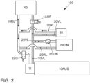
- the Figure 2 shows the cold start system 100 according to the invention in a second operating mode with an internal combustion engine 10 in the non-operating state 10OFF.
- the switching valve 1 is 1OPEN and the switching valve 2 is 2CLOSED.
- the auxiliary heater 20 and the preheating circuit pump 21 are in operation 20ON, 21ON.
- the gas pressure regulator 30 is heated and protected from freezing via the heating output of the auxiliary heating unit 20 and the pumping output of the preheating circuit pump 21, since the circuit 20VL ⁇ 30VL ⁇ 30RL ⁇ 10RL ⁇ 20RL is active.
- circuit 20VL ⁇ 10VL ⁇ 10RL ⁇ 20RL is active due to the open switching valve 1AUF, so that parallel to the heating of the gas pressure regulator 30, the vehicle interior is supplied with heat via the interior heater 40.
- the Figure 3 shows the cold start system 100 according to the invention in a third operating mode with an internal combustion engine 10 in the non-operating state 10OFF.
- the switching valve 1 is 1CLOSED closed and the switching valve 2 is 2OPEN opened.
- the auxiliary heater 20 and the preheating circuit pump 21 are in operation 20ON, 21ON.
- the gas pressure regulator 30 is heated and protected from freezing via the heating output of the auxiliary heating unit 20 and the pumping output of the preheating circuit pump 21, since the circuit 20VL ⁇ 30VL ⁇ 30RL ⁇ 10RL ⁇ 20RL is active.
- circuit 20VL ⁇ 10VL ⁇ 30VL ⁇ 30RL ⁇ 10RL ⁇ via 2AUF ⁇ 10VL ⁇ 30VL ⁇ 30RL is active due to the open switching valve 2AUF, so that the cooling circuit of the internal combustion engine is supplied with heat in parallel with the heating of the gas pressure regulator 30.
- the Figure 4 shows the cold start system 100 according to the invention in a fourth operating mode with an internal combustion engine 10 in the non-operating state 10OFF.
- the switching valves 1 and 2 are 1OP and 2OP open.
- the auxiliary heater 20 and the preheating circuit pump 21 are in operation 20ON, 21ON.
- the gas pressure regulator 30 is heated and protected from freezing by the heating output of the auxiliary heating unit 20 and the pumping output of the preheating circuit pump 21, since the circuit 20VL ⁇ 30VL ⁇ 30RL ⁇ 10RL ⁇ 20RL is active. Furthermore, the circuit 20VL ⁇ 10VL ⁇ 10RL ⁇ 20RL is active due to the open switching valve 1AUF, so that in parallel with the heating of the gas pressure regulator 30, the vehicle interior is supplied with heat via the interior heating 40.
- the switching valve 2AUF is also open also preheats the cooling circuit of the internal combustion engine 10, since the circuit 10VL ⁇ 10RL is now also active via the open switching valve 2AUF.
- the four operating modes described above can also be operated when the internal combustion engine 10 is in the operating state 10ON and the internal combustion engine 10 and the cooling module 11 and its engine-side driven cooling water pump (not shown) are in operation.
- the situation is different in the seventh operating mode compared to the third operating mode according to the Figures 3 and 7 and in the eighth compared to the fourth operating mode according to the Figures 4 and 8th in which the internal combustion engine 10 is either in the operating state 10OFF (third and fourth operating mode) or in the operating state 10ON (seventh and eighth operating mode) and the internal combustion engine 10 and the cooling module 11 and its engine-side driven cooling water pump (not shown) are in operation.
- both switching valves 1 and 2 are open 1AUF, 2AUF, so that the circuit 10VL ⁇ 10RL is open via the cooling module 11 at least in the direction of the cooling circuit via 2AUF of the internal combustion engine 10 or even in the direction of the cooling circuit of the internal combustion engine 10 and in the direction of the interior via 1AUF and 2AUF.
- the auxiliary heating unit 20 supplies heat to the cooling circuit of the internal combustion engine 10 via the circuit 20VL ⁇ 10VL ⁇ 30VL --+ 30RL ⁇ 10RL ⁇ via 2AUF ⁇ 10VL ⁇ 30VL --+ 30RL, so that the cooling circuit heats up without the internal combustion engine 10 being in operation 10OFF.
- the auxiliary heating unit 20 provides heat in the cooling circuit of the internal combustion engine 10ON via the analog circuit 20VL ⁇ 10VL ⁇ 30VL ⁇ 30RL ⁇ 10RL ⁇ via 2AUF ⁇ 10VL ⁇ 30VL ⁇ 30RL if required, whereby now, in contrast to the third and fourth operating modes, heat is also generated in the cooling circuit of the internal combustion engine itself, so that the internal combustion engine 10 and the entire cold start system 100 are heated up more quickly overall, so that the heat input in these operating modes is increased overall by the heat generated in the area of the internal combustion engine 10 and cooling module 11, or if necessary the heating output of the auxiliary heating unit 20 and/or the pumping output of the preheating circuit pump 21 as control parameters of the cold start system 100 can be reduced compared to the operating modes in which the internal combustion engine 10 and the cooling module 11 are not in operation 10OFF.
- the preheating of the gas pressure regulator 30 begins with the aid of the auxiliary heating unit 20 at the moment the vehicle is opened by remote control and/or by activating the door contact switch, whereby it is provided that the user can, for example, select whether the vehicle interior should already be heated via the interior heating 40. In other words, the user thus chooses between the first and second operating mode (according to the Figures 1 and Figure 2 ) out of.
- the user switches on the auxiliary heating unit 20 before starting up the internal combustion engine 10 in order to heat the vehicle interior via the interior heating 40.
- the gas pressure regulator 30 is also automatically supplied with heat.
- a monovalent internal combustion engine 10 can advantageously take full advantage of the high knock resistance of gas, in particular CNG as fuel, by increasing the compression ratio, since the gas pressure regulator 30 is protected from freezing during cold starts and during the warm-up phase when the gas is released to a lower operating pressure, as explained above.
- gas pressure regulator 30 is protected from freezing during cold starts and during the warm-up phase when the gas is released to a lower operating pressure, as explained above.
- bivalent fuel supply systems for two fuel and injection or blowing systems (petrol for the auxiliary heating unit and gas for the internal combustion engine) to be integrated.
Landscapes
- Engineering & Computer Science (AREA)
- Chemical & Material Sciences (AREA)
- Mechanical Engineering (AREA)
- Combustion & Propulsion (AREA)
- General Engineering & Computer Science (AREA)
- General Chemical & Material Sciences (AREA)
- Oil, Petroleum & Natural Gas (AREA)
- Chemical Kinetics & Catalysis (AREA)
- Life Sciences & Earth Sciences (AREA)
- Atmospheric Sciences (AREA)
- Physics & Mathematics (AREA)
- Thermal Sciences (AREA)
- Air-Conditioning For Vehicles (AREA)
- Combined Controls Of Internal Combustion Engines (AREA)
- Output Control And Ontrol Of Special Type Engine (AREA)
Claims (6)
- Système de démarrage à froid (100) pour un moteur à combustion interne monovalent (10) fonctionnant avec un gaz, comprenant au moins un groupe de chauffage auxiliaire (20) fonctionnant également avec le gaz, qui chauffe un fluide de circuit qui est guidé dans un circuit de préchauffage du chauffage auxiliaire (20VL, 20RL), dans lequel est agencée une pompe de circuit de préchauffage (21), un aller (20VL) du circuit de préchauffage du chauffage auxiliaire (20VL, 20RL) présentant au moins une première dérivation vers un aller (30VL) d'un circuit de chauffage (30VL, 30RL) d'au moins un composant à chauffer, dont le retour (30RL) est intégré dans le retour (20RL) du circuit de préchauffage du chauffage auxiliaire (20VL, 20RL), caractérisé en ce que le composant à chauffer est un régulateur de pression de gaz (30) d'un système d'alimentation en carburant du moteur à combustion interne monovalent (10).
- Système de démarrage à froid (100) selon la revendication 1, caractérisé en ce que l'aller (20VL) du circuit de préchauffage du chauffage auxiliaire (20VL, 20RL) présente une deuxième dérivation qui débouche dans un circuit de chauffage d'habitacle (10VL, 10RL), le circuit de chauffage d'habitacle (10VL, 10RL) étant en liaison côté fluide avec un circuit de refroidissement pouvant s'ouvrir en fonction de la température pour refroidir le moteur à combustion interne (10), des soupapes (1, 2) commutables et/ou réglables étant agencées dans le circuit de chauffage d'habitacle (10VL, 10RL), lesquelles ferment ou libèrent l'aller (10VL) et/ou le retour (10RL) du circuit de chauffage d'habitacle (10VL, 10RL) en fonction de modes de fonctionnement pouvant être prédéfinis.
- Système de démarrage à froid (100) selon les revendications 1 et 2, caractérisé en ce qu'un retour (30RL) du circuit de chauffage (30VL, 30RL) du régulateur de pression de gaz (30) à chauffer est couplé dans le retour (10RL) du circuit de chauffage d'habitacle (10VL, 10RL), de telle sorte que le retour (20RL) du circuit de préchauffage du chauffage auxiliaire (20VL, 20RL) passe également par le retour (10RL) du circuit de chauffage d'habitacle (10VL, 10RL).
- Système de démarrage à froid (100) selon les revendications 1 et 2, caractérisé en ce qu'une première soupape commutable et/ou réglable (1) est agencée dans l'aller (10VL) du circuit de chauffage d'habitacle (10VL, 10RL) en aval de la première et de la deuxième dérivation avant le circuit de refroidissement pouvant s'ouvrir en fonction de la température pour refroidir le moteur à combustion interne (10).
- Système de démarrage à froid (100) selon les revendications 1 et 2, caractérisé en ce qu'une deuxième soupape commutable et/ou réglable (2) est agencée dans le retour (10RL) du circuit de chauffage d'habitacle (10VL, 10RL) en aval du couplage du retour (30RL) du circuit de chauffage (30VL, 30RL) du régulateur de pression de gaz (30) à chauffer et du retour (20RL) du circuit de préchauffage du chauffage auxiliaire (20VL, 20RL) avant le chauffage de l'habitacle (40).
- Système de démarrage à froid (100) selon les revendications 2 et 3, caractérisé en ce que le circuit de refroidissement pouvant être ouvert en fonction de la température pour refroidir le moteur à combustion interne (10) et le circuit de chauffage d'habitacle (10VL, 10RL) sont reliés au moins côté fluide par un module de refroidissement (11) associé au moteur à combustion interne (10), une pompe à eau de refroidissement étant agencée dans le circuit de refroidissement, laquelle active le circuit de chauffage d'habitacle (10VL, 10RL) dès que le moteur à combustion interne (10EIN) est en marche, dans la mesure où les deux soupapes (1, 2) commutables et/ou réglables sont actionnées au moins dans une position partiellement ouverte (1AUF, 2AUF).
Applications Claiming Priority (2)
| Application Number | Priority Date | Filing Date | Title |
|---|---|---|---|
| DE102019125395.0A DE102019125395A1 (de) | 2019-09-20 | 2019-09-20 | Kaltstart-System und ein zugehöriges Verfahren für ein mit verdichtetem Gas betriebenes Fahrzeug mit einer monovalenten Kraftstoffversorgung |
| PCT/EP2020/075928 WO2021053048A2 (fr) | 2019-09-20 | 2020-09-17 | Système de démarrage à froid et procédé correspondant pour un véhicule fonctionnant au moyen de gaz comprimé et présentant une alimentation en carburant de type monocarburation |
Publications (2)
| Publication Number | Publication Date |
|---|---|
| EP4031761A2 EP4031761A2 (fr) | 2022-07-27 |
| EP4031761B1 true EP4031761B1 (fr) | 2024-05-01 |
Family
ID=72665219
Family Applications (1)
| Application Number | Title | Priority Date | Filing Date |
|---|---|---|---|
| EP20781309.8A Active EP4031761B1 (fr) | 2019-09-20 | 2020-09-17 | Système de démarrage à froid pour un véhicule fonctionnant au moyen de gaz comprimé et présentant une alimentation en carburant de type monocarburation |
Country Status (3)
| Country | Link |
|---|---|
| EP (1) | EP4031761B1 (fr) |
| DE (1) | DE102019125395A1 (fr) |
| WO (1) | WO2021053048A2 (fr) |
Family Cites Families (8)
| Publication number | Priority date | Publication date | Assignee | Title |
|---|---|---|---|---|
| DE4042123A1 (de) * | 1990-12-28 | 1992-07-02 | Eberspaecher J | Mit einem heizgeraet versehener kuehlmittelkreislauf eines fahrzeugmotors |
| IT1391286B1 (it) * | 2007-07-24 | 2011-12-01 | Ventrex Automotive Gmbh | Impianto a serbatoio e di alimentazione di combustibile per motori a combustione interna |
| DE102014218632A1 (de) * | 2014-09-17 | 2016-03-17 | Continental Automotive Gmbh | Vorrichtung zur Kraftstoffversorgung, Verfahren zum Betreiben einer Vorrichtung zur Kraftstoffversorgung und Computerprogrammprodukt |
| DE102014219500A1 (de) * | 2014-09-26 | 2016-03-31 | Continental Automotive Gmbh | Vorrichtung zur Kraftstoffversorgung für ein mit verflüssigtem oder verdichtetem Gas betriebenes Fahrzeug, Verfahren zum Betreiben einer Vorrichtung zur Kraftstoffversorgung und Computerprogrammprodukt |
| DE102016107207B4 (de) * | 2016-03-17 | 2020-07-09 | Eberspächer Climate Control Systems GmbH & Co. KG | Brennstoffgasbetriebenes Fahrzeugheizgerät |
| DE102016105048A1 (de) * | 2016-03-18 | 2017-09-21 | Volkswagen Aktiengesellschaft | Brennkraftmaschine und Verfahren zum Betreiben einer Brennkraftmaschine |
| FR3066556B1 (fr) * | 2017-05-17 | 2019-06-21 | Peugeot Citroen Automobiles Sa | Groupe motopropulseur avec source de chaleur additionnelle integree dans un circuit de fluide caloporteur |
| DE102017218824A1 (de) * | 2017-10-23 | 2019-04-25 | Volkswagen Aktiengesellschaft | Verfahren und Vorrichtung zur Kraftstoffversorgung einer mit einem gasförmigen Kraftstoff betreibbaren Brennkraftmaschine |
-
2019
- 2019-09-20 DE DE102019125395.0A patent/DE102019125395A1/de active Pending
-
2020
- 2020-09-17 EP EP20781309.8A patent/EP4031761B1/fr active Active
- 2020-09-17 WO PCT/EP2020/075928 patent/WO2021053048A2/fr unknown
Also Published As
| Publication number | Publication date |
|---|---|
| WO2021053048A3 (fr) | 2021-05-14 |
| DE102019125395A1 (de) | 2021-03-25 |
| WO2021053048A2 (fr) | 2021-03-25 |
| EP4031761A2 (fr) | 2022-07-27 |
Similar Documents
| Publication | Publication Date | Title |
|---|---|---|
| DE102008035955B4 (de) | Kühlstrategie | |
| EP1913243B1 (fr) | Systeme de refroidissement pour vehicule et procede pour actionner un systeme de refroidissement | |
| DE102010054912B4 (de) | Dosieranordnung und Verfahren zum Betreiben einer Dosieranordnung | |
| DE102012105632A1 (de) | Wärmespeichervorrichtung für ein Fahrzeug | |
| DE102006011797A1 (de) | Fahrzeug oder stationäre Kraftanlage mit einer aufgeladenen Brennkraftmaschine als Antriebsquelle | |
| EP1192351A2 (fr) | Dispositif d'alimentation en carburant pour moteur a combustion interne | |
| WO2014177513A1 (fr) | Circuit de refroidissement | |
| DE102008024561A1 (de) | Verfahren zum Betreiben einer Verbrennungskraftmaschine | |
| EP2357349A1 (fr) | Système d'utilisation de la chaleur dégagée d'un moteur à combustion interne doté d'un dispositif de protection antigel | |
| DE102017108400A1 (de) | Temperieranordnung für einen elektrischen Energiespeicher | |
| EP2345803A1 (fr) | Circuit de refroidissement d'un moteur à combustion interne et procédé de travail pour le fonctionnement d'un circuit de refroidissement | |
| WO2012019707A1 (fr) | Moteur à combustion interne à carburant liquide et gazeux | |
| EP3191702B1 (fr) | Procédé pour réchauffer un carburant et système de réchauffage de carburant | |
| AT513999B1 (de) | Abwärmenutzungssystem, insbesondere für ein Kraftfahrzeug, mit einer Speisepumpe | |
| EP4031761B1 (fr) | Système de démarrage à froid pour un véhicule fonctionnant au moyen de gaz comprimé et présentant une alimentation en carburant de type monocarburation | |
| EP3405660B1 (fr) | Système de refroidissement après arrêt du moteur et procédé permettant de faire fonctionner un tel système | |
| EP2108813B1 (fr) | Dispositif de refroidissement ou de chauffage d'un moteur à combustion interne | |
| EP3640069B1 (fr) | Véhicule automobile pourvu de récipient à liquide | |
| EP3191701B1 (fr) | Procédé pour réchauffer un carburant ainsi que système de chauffage de réservoir et système de réchauffage de carburant | |
| DE102010049713A1 (de) | Verfahren zum Betreiben eines Verdampfers für Flüssiggas und Verdampfer | |
| DE102011075557A1 (de) | Leitungskreis und Verfahren zum Betreiben eines Leitungskreises zur Abwärmenutzung einer Brennkraftmaschine | |
| DE102007044165A1 (de) | Vorrichtung zum Betrieb von Motoranlagen mit Pflanzenöl | |
| DE102013211701A1 (de) | Fahrzeugheizsystem sowie Verfahren zum Heizen des Innenraums eines Fahrzeugs mit einem Fahrzeugheizsystem | |
| DE102012203257A1 (de) | Betriebsverfahren für ein Brennkraftmaschinen-Kraftstoffsystem | |
| WO2018050408A1 (fr) | Système de récupération de chaleur perdue |
Legal Events
| Date | Code | Title | Description |
|---|---|---|---|
| STAA | Information on the status of an ep patent application or granted ep patent |
Free format text: STATUS: UNKNOWN |
|
| STAA | Information on the status of an ep patent application or granted ep patent |
Free format text: STATUS: THE INTERNATIONAL PUBLICATION HAS BEEN MADE |
|
| PUAI | Public reference made under article 153(3) epc to a published international application that has entered the european phase |
Free format text: ORIGINAL CODE: 0009012 |
|
| STAA | Information on the status of an ep patent application or granted ep patent |
Free format text: STATUS: REQUEST FOR EXAMINATION WAS MADE |
|
| 17P | Request for examination filed |
Effective date: 20220420 |
|
| AK | Designated contracting states |
Kind code of ref document: A2 Designated state(s): AL AT BE BG CH CY CZ DE DK EE ES FI FR GB GR HR HU IE IS IT LI LT LU LV MC MK MT NL NO PL PT RO RS SE SI SK SM TR |
|
| DAV | Request for validation of the european patent (deleted) | ||
| DAX | Request for extension of the european patent (deleted) | ||
| GRAP | Despatch of communication of intention to grant a patent |
Free format text: ORIGINAL CODE: EPIDOSNIGR1 |
|
| STAA | Information on the status of an ep patent application or granted ep patent |
Free format text: STATUS: GRANT OF PATENT IS INTENDED |
|
| INTG | Intention to grant announced |
Effective date: 20231219 |
|
| P01 | Opt-out of the competence of the unified patent court (upc) registered |
Effective date: 20240110 |
|
| GRAS | Grant fee paid |
Free format text: ORIGINAL CODE: EPIDOSNIGR3 |
|
| GRAA | (expected) grant |
Free format text: ORIGINAL CODE: 0009210 |
|
| STAA | Information on the status of an ep patent application or granted ep patent |
Free format text: STATUS: THE PATENT HAS BEEN GRANTED |
|
| AK | Designated contracting states |
Kind code of ref document: B1 Designated state(s): AL AT BE BG CH CY CZ DE DK EE ES FI FR GB GR HR HU IE IS IT LI LT LU LV MC MK MT NL NO PL PT RO RS SE SI SK SM TR |
|
| REG | Reference to a national code |
Ref country code: GB Ref legal event code: FG4D Free format text: NOT ENGLISH |
|
| REG | Reference to a national code |
Ref country code: CH Ref legal event code: EP |
|
| REG | Reference to a national code |
Ref country code: IE Ref legal event code: FG4D Free format text: LANGUAGE OF EP DOCUMENT: GERMAN |
|
| REG | Reference to a national code |
Ref country code: DE Ref legal event code: R096 Ref document number: 502020007891 Country of ref document: DE |
|
| REG | Reference to a national code |
Ref country code: LT Ref legal event code: MG9D |
|
| REG | Reference to a national code |
Ref country code: NL Ref legal event code: MP Effective date: 20240501 |