EP4030746A1 - Image processing device and stereo camera device using same - Google Patents
Image processing device and stereo camera device using same Download PDFInfo
- Publication number
- EP4030746A1 EP4030746A1 EP20862427.0A EP20862427A EP4030746A1 EP 4030746 A1 EP4030746 A1 EP 4030746A1 EP 20862427 A EP20862427 A EP 20862427A EP 4030746 A1 EP4030746 A1 EP 4030746A1
- Authority
- EP
- European Patent Office
- Prior art keywords
- image
- geometric correction
- unit
- processing device
- exposure
- Prior art date
- Legal status (The legal status is an assumption and is not a legal conclusion. Google has not performed a legal analysis and makes no representation as to the accuracy of the status listed.)
- Pending
Links
Images


Classifications
-
- G—PHYSICS
- G01—MEASURING; TESTING
- G01C—MEASURING DISTANCES, LEVELS OR BEARINGS; SURVEYING; NAVIGATION; GYROSCOPIC INSTRUMENTS; PHOTOGRAMMETRY OR VIDEOGRAMMETRY
- G01C3/00—Measuring distances in line of sight; Optical rangefinders
- G01C3/10—Measuring distances in line of sight; Optical rangefinders using a parallactic triangle with variable angles and a base of fixed length in the observation station, e.g. in the instrument
-
- H—ELECTRICITY
- H04—ELECTRIC COMMUNICATION TECHNIQUE
- H04N—PICTORIAL COMMUNICATION, e.g. TELEVISION
- H04N13/00—Stereoscopic video systems; Multi-view video systems; Details thereof
- H04N13/20—Image signal generators
- H04N13/204—Image signal generators using stereoscopic image cameras
- H04N13/239—Image signal generators using stereoscopic image cameras using two 2D image sensors having a relative position equal to or related to the interocular distance
-
- H—ELECTRICITY
- H04—ELECTRIC COMMUNICATION TECHNIQUE
- H04N—PICTORIAL COMMUNICATION, e.g. TELEVISION
- H04N13/00—Stereoscopic video systems; Multi-view video systems; Details thereof
- H04N13/20—Image signal generators
- H04N13/296—Synchronisation thereof; Control thereof
-
- H—ELECTRICITY
- H04—ELECTRIC COMMUNICATION TECHNIQUE
- H04N—PICTORIAL COMMUNICATION, e.g. TELEVISION
- H04N23/00—Cameras or camera modules comprising electronic image sensors; Control thereof
- H04N23/45—Cameras or camera modules comprising electronic image sensors; Control thereof for generating image signals from two or more image sensors being of different type or operating in different modes, e.g. with a CMOS sensor for moving images in combination with a charge-coupled device [CCD] for still images
-
- G—PHYSICS
- G03—PHOTOGRAPHY; CINEMATOGRAPHY; ANALOGOUS TECHNIQUES USING WAVES OTHER THAN OPTICAL WAVES; ELECTROGRAPHY; HOLOGRAPHY
- G03B—APPARATUS OR ARRANGEMENTS FOR TAKING PHOTOGRAPHS OR FOR PROJECTING OR VIEWING THEM; APPARATUS OR ARRANGEMENTS EMPLOYING ANALOGOUS TECHNIQUES USING WAVES OTHER THAN OPTICAL WAVES; ACCESSORIES THEREFOR
- G03B35/00—Stereoscopic photography
- G03B35/08—Stereoscopic photography by simultaneous recording
-
- H—ELECTRICITY
- H04—ELECTRIC COMMUNICATION TECHNIQUE
- H04N—PICTORIAL COMMUNICATION, e.g. TELEVISION
- H04N13/00—Stereoscopic video systems; Multi-view video systems; Details thereof
- H04N13/10—Processing, recording or transmission of stereoscopic or multi-view image signals
- H04N13/106—Processing image signals
- H04N13/133—Equalising the characteristics of different image components, e.g. their average brightness or colour balance
-
- H—ELECTRICITY
- H04—ELECTRIC COMMUNICATION TECHNIQUE
- H04N—PICTORIAL COMMUNICATION, e.g. TELEVISION
- H04N13/00—Stereoscopic video systems; Multi-view video systems; Details thereof
- H04N13/20—Image signal generators
- H04N13/204—Image signal generators using stereoscopic image cameras
- H04N13/246—Calibration of cameras
-
- H—ELECTRICITY
- H04—ELECTRIC COMMUNICATION TECHNIQUE
- H04N—PICTORIAL COMMUNICATION, e.g. TELEVISION
- H04N25/00—Circuitry of solid-state image sensors [SSIS]; Control thereof
- H04N25/50—Control of the SSIS exposure
- H04N25/53—Control of the integration time
- H04N25/531—Control of the integration time by controlling rolling shutters in CMOS SSIS
Definitions
- the present invention relates to an image processing device that processes images captured by a plurality of rolling shutter-type image sensors (cameras), and an invehicle stereo camera device that recognizes an obstacle outside a vehicle using the image processing device and a plurality of cameras.
- image processing device that processes images captured by a plurality of rolling shutter-type image sensors (cameras), and an invehicle stereo camera device that recognizes an obstacle outside a vehicle using the image processing device and a plurality of cameras.
- a sensor for monitoring the front of the vehicle there are a millimeter wave radar, a laser radar, a camera, and the like.
- a type of camera there are a monocular camera and a stereo camera using a plurality of cameras.
- the stereo camera can measure a distance to a photographed object by using parallax of an overlapping region of images photographed by two cameras at a predetermined interval (for example, see PTL 1). Therefore, it is possible to accurately grasp the risk of collision to the object ahead.
- the stereo camera obtains parallax between images captured by the two cameras and transforms the parallax into a distance.
- the rolling shutter type is a type of photographing pixels of sensors disposed two-dimensionally while shifting exposure timings in units of rasters.
- PTL 2 proposes a method of correcting a distance difference between the upper and lower sides of the image.
- PTL 2 proposes a method of adjusting all the parallaxes in an image to the parallax of a reference time by correcting the parallax based on the reference time by a delay amount of the exposure timing for each pixel from the reference time.
- the influence of the rolling shutter type on the parallax of the stereo camera has the following problems in addition to the above problems.
- An object of the present invention is to provide an image processing device capable of reducing an error in parallax calculation of stereo matching processing, and a stereo camera device using the image processing device.
- An image processing device includes a geometric correction unit configured to correct distortion of images captured by a plurality of rolling shutter-type image sensors mounted in a vehicle, a parallax calculation unit configured to calculate a parallax using a corrected image that is corrected by the geometric correction unit, and an exposure time difference adjusting unit configured to adjust a geometric correction position of at least one image based on a difference between a geometric correction amount used for distortion correction of an image serving as a reference and a geometric correction amount used for distortion correction of other images and vehicle information regarding a position or movement of the vehicle.
- pixels on the same raster of the respective images become images with the same exposure timing, and thus, there is an effect that an error in parallax calculation of the stereo matching processing can be reduced.
- FIG. 1 illustrates a system configuration diagram of a stereo camera device 10 on which an image processing device 20 according to a first embodiment is mounted.
- the stereo camera device 10 is mounted on a vehicle (hereinafter, it may be referred to as an own vehicle) not illustrated, and mainly includes a pair of left and right cameras (a left camera 21 and a right camera 22) arranged at predetermined intervals (side by side) so as to photograph the periphery (for example, the front) of the vehicle, and the image processing device 20 that processes images (hereinafter, the image may be referred to as a camera image) of the cameras.
- a vehicle hereinafter, it may be referred to as an own vehicle
- the image processing device 20 that processes images (hereinafter, the image may be referred to as a camera image) of the cameras.
- two cameras of the right camera 22 and the left camera 21 capture images around the vehicle.
- An optical lens 24 and an image sensor 220 are mounted in the right camera 22, and an optical lens 23 and an image sensor 210 are mounted in the left camera 21.
- the image sensors 220 and 210 are a rolling shutter type.
- An angle of view and a focal distance of the image captured by the camera are determined by an optical lens.
- An image captured through the optical lens is distorted. The geometric correction is performed to correct the distortion.
- the images (images with distortion) captured by the right camera 22 and the left camera 21 are input to the image processing device 20.
- the image processing device 20 includes a microcomputer including a CPU (Central Processing Unit), a memory, and the like, and the CPU executes various processes described below according to instructions of a program stored in the memory.
- CPU Central Processing Unit
- the image processing device 20 includes a geometric correction (left) unit 25, a geometric correction (right) unit 26, a geometric correction table left 27, a geometric correction table right 28, a parallax calculation unit 30, an object detection unit 40, a vehicle control unit 50, an exposure time difference adjusting unit 60, a road surface estimation unit 70, and a table reference coordinate generation unit 80, which are communicably connected via a communication line.
- the geometric correction (right) unit 26 corrects the image of the right camera 22 (which may be referred to as a right image or a right camera image), and the geometric correction (left) unit 25 corrects the image of the left camera 21 (which may be referred to as a left image or a left camera image).
- the geometric correction processing of the image is performed using the geometric correction table.
- the geometric correction table right 28 is a table for correcting the photographed image of the right camera 22, and is input to the geometric correction (right) unit 26.
- the geometric correction table left 27 is a table for correcting the photographed image of the left camera 21, and is input to the geometric correction (left) unit 25.
- the images (corrected images) corrected by the geometric correction (right) unit 26 and the geometric correction (left) unit 25 are input to the parallax calculation unit 30.
- a table method using a geometric correction table is adopted as the geometric correction processing of the image, but for example, a geometric correction value used for the geometric correction processing (distortion correction processing) may be calculated and obtained using a mathematical expression or the like.
- the exposure time difference adjusting unit 60 is a unit that corrects a deviation between the left and right images caused by a deviation in the exposure time (exposure timing) between the image captured by the right camera 22 and the image captured by the left camera 21.
- the deviation between the left and right images is caused by a deviation in the exposure time in a part of both images when the left and right images are geometrically corrected.
- the exposure time difference adjusting unit 60 includes a time difference calculation unit 601 that calculates an exposure time difference by using a difference in correction amount between the geometric correction table right 28 and the geometric correction table left 27, and a coordinate adjustment unit 602 that corrects an image by using the exposure time difference and a vehicle signal (vehicle information) such as a vehicle speed and a steering angle (details will be described later).
- the table reference coordinate generation unit 80 sequentially generates coordinates (x, y) to refer to the geometric correction table (the geometric correction table right 28 and the geometric correction table left 27) in order to perform geometric correction on the entire image from the upper left to the lower right.
- the parallax calculation unit 30 uses the image corrected by the geometric correction (right) unit 26 as a reference image, and performs stereo matching processing in order to calculate parallax data with the image corrected by the geometric correction (left) unit 25.
- the parallax data is generated for each pixel of the entire image.
- the parallax data generated by the parallax calculation unit 30 is input to the road surface estimation unit 70 and the object detection unit 40.
- the road surface estimation unit 70 extracts a portion of the road surface on which the own vehicle is traveling in the parallax data from the image, and calculates a parameter of the road surface.
- the parameter of the road surface calculated by road surface estimation unit 70 is input to the object detection unit 40.
- the object detection unit 40 Based on the parallax data from the parallax calculation unit 30 and the parameter of the road surface from the road surface estimation unit 70, the object detection unit 40 detects a three-dimensional object on the road surface using the parallax data and the image data. The information detected by the object detection unit 40 is input to the vehicle control unit 50.
- the vehicle control unit 50 When the three-dimensional object detected by the object detection unit 40 becomes an obstacle to traveling, the vehicle control unit 50 generates and outputs a control instruction for controlling a brake, a suspension, and the like provided in the vehicle in order to avoid a collision with the obstacle or reduce an impact due to the collision.
- FIG. 2 is a diagram illustrating images before and after geometric correction of lens distortion of a camera image.
- a right camera image 2200 becomes an image distorted by the optical lens 24.
- a geometrically transformed right image 2201 is obtained.
- a curve 2203 in the right camera image 2200 is a straight line 2202 in the geometrically transformed right image 2201.
- a left camera image 2100 becomes an image distorted by the optical lens 23.
- a geometrically transformed left image 2101 is obtained.
- a curve 2103 in the left camera image 2100 is a straight line 2102 in the geometrically transformed left image 2101.
- the y coordinate of the curve 2203 and the y coordinate of the curve 2103 before transformation of these straight lines may be different.
- the image sensors 220 and 210 as optical sensors (such as a CCD sensor or a CMOS sensor) of the right camera 22 and the left camera 21 are the rolling shutter type, the exposure time of the curve 2203 and the exposure time of the curve 2103 are shifted from each other. This is because the exposure time of the rolling shutter is shifted in units of rasters.
- the subject is photographed while shifted to the same y coordinate in the left and right images (the geometrically transformed right image 2201 and the geometrically transformed left image 2101) after the geometric correction.
- FIG. 3 is a diagram illustrating an example in which a subject is shifted and photographed at the same y coordinate of left and right images.
- the object 2104 on the road surface of the geometrically transformed left image 2101 and the object 2204 on the road surface of the geometrically transformed right image 2201 are the same object but have a shift in the y coordinate on the image. Since the stereo matching processing is based on the premise that the same subject is photographed at the same y coordinate on the left and right when the parallax between the left and right images is calculated, an error occurs in the stereo matching in this case. The reason why the y coordinates of the object 2104 and the object 2204 are shifted as illustrated in FIG.
- FIG. 4 is a diagram illustrating an example of geometric correction processing using a geometric correction table.
- the left camera image 2100 has 64 pixels of 8 pixels in the x direction and 8 pixels in the y direction
- the geometrically transformed left image 2101 has 64 pixels of 8 pixels in the x direction and 8 pixels in the y direction.
- the moving distance and the moving direction of the vehicle are calculated based on the deviation amount, and the positional deviation of one of the left and right images is corrected.
- the right image is used as the reference image for the stereo processing, and the left image is corrected.
- the numerical value of the geometric correction table is expressed in an integer format, but it is also possible to express the numerical value in a small number format for improving accuracy.
- the geometric correction table may be thinned out to about 8 pixel units, and the pixels therebetween may be interpolated to reduce the table size.
- FIG. 5 is a diagram illustrating correspondence between a two-dimensional image 500 indicated by x and y coordinates and a three-dimensional space indicated by X, Y, and Z.
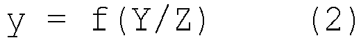
- a two-dimensional image 500 indicated by x and y coordinates When the point Q in the three-dimensional space is displayed at the point q of the two-dimensional image 500, the following Expressions (1) and (2) are obtained.
- f represents a focal distance. If (x, y) on the image and Z of the pixel are known, X and Y are determined by converting Expressions (1) and (2) .
- FIG. 6 is a diagram illustrating an example of an image obtained by photographing a road surface 603 during traveling. Assuming that the road surface 603 is a flat surface and has no inclination in the lateral direction, the relationship between the y coordinate and the Z value on the road surface 603 is represented by the following Expression (3) .
- ⁇ is a y coordinate of a vanishing point 604, and ⁇ is a parameter of the road surface obtained by a ground height, a focal distance, or the like of the camera.
- y ⁇ ⁇ ⁇ / Z
- Expression (3) is converted into an expression for obtaining a Z value to calculate a Z value from the y coordinate on the road surface 603, and x and y on the road surface 603 and the Z value are applied to the expressions obtained by converting Expressions (1) and (2) to obtain X and Y, the coordinates (X, Y, Z) of a three-dimensional space corresponding to a point (x, y) of the object 2104 on the road surface 603 can be calculated.
- the moving distance and the moving direction of the vehicle obtained from the difference between the y coordinate values of the left and right geometric correction table illustrated in FIG.
- the time difference calculation unit 601 of the exposure time difference adjusting unit 60 illustrated in FIG. 1 compares the correction data (correction amount) indicated at the same coordinate position in the left and right geometric correction tables (the geometric correction table right 28 and the geometric correction table left 27) to obtain the difference, and multiplies (in consideration of) the time difference of the exposure timing per raster to obtain the deviation amount (exposure time difference) of the exposure timing between the same coordinates of the left and right geometrically corrected images.
- the coordinate adjustment unit 602 of the exposure time difference adjusting unit 60 corrects the positional deviation of the image, in other words, adjusts the geometric correction position of the left image, using the deviation amount (exposure time difference) of the exposure timing and the vehicle information regarding the position or movement of the vehicle.
- the vehicle information includes a turning angle, an own vehicle speed, and the like, and is obtained from, for example, a steering angle, a yaw rate, and a speed sensor mounted on the vehicle.
- a turning angle, an own vehicle speed, and the like may be calculated from an own vehicle position. As a result, it is possible to calculate the moving distance and the moving direction of the vehicle that has moved in the deviation period of the exposure timing.
- FIG. 7 illustrates an operation flow of the stereo camera device 10.
- images are captured by the right camera 22 and the left camera 21 (S100).
- the geometric transformation processing is performed to correct lens distortion of the image.
- the table reference coordinate generation unit 80 updates the coordinates (x, y) to which the geometric correction table is referred (S110).
- the exposure time difference adjusting unit 60 calculates reference coordinates (x', y') of the left image based on the exposure time difference between the left and right images (S120). Details of this portion will be described later based on FIG. 8 .
- the geometric correction table right 28 for correction of the right image is accessed with coordinates (x, y), and the geometric correction table left 27 for correction of the left image is accessed with coordinates (x', y').
- the geometric correction (right) unit 26 and the geometric correction (left) unit 25 perform image correction processing as illustrated in FIG. 4 (S130). This correction processing is performed on the entire image (S140).
- the parallax calculation unit 30 uses the geometrically corrected left and right images to generate parallax data (S150).
- the road surface estimation unit 70 creates a road surface parameter ( ⁇ , ⁇ ) using the parallax data (S160).
- the object detection unit 40 detects an object on the road surface, calculates a position, a distance, and a size of the object, and detects the road obstacle (S170).
- the vehicle control unit 50 generates a control instruction for controlling the brake, the suspension, and the like according to the position of the road obstacle so as not to cause an obstacle in traveling of the own vehicle (S180), and then determines the ending of the system (S190).
- FIG. 8 illustrates a processing flow of the exposure time difference adjusting unit 60 (the processing flow of S120 in FIG. 7 described above).
- the left and right geometric correction tables are accessed in accordance with (x, y), and a difference s in the number of rasters is obtained from the difference between the correction coordinate values recorded in the left and right geometric correction tables as illustrated in FIG. 4 (S200). This s is indicated by a table indicating the deviation in exposure time (a difference in exposure timing for each pixel) with a time ratio in units of rasters.
- the exposure time difference r between the left and right cameras of the pixel of (x, y) is obtained (by the time difference calculation unit 601) from the difference s (S210).
- the exposure time difference per raster of the image sensor is ⁇
- a distance w and a direction (u, v) in which the vehicle has moved during the period of the exposure time difference r are obtained based on vehicle information such as an own vehicle speed and a turning angle (S220).
- vehicle information such as an own vehicle speed and a turning angle (S220).
- the coordinates of the correction portion (x, y) of the left image are converted into (X, Y, Z) in a three-dimensional space using Expressions (1), (2), and (3) (S230).
- the (u, v, w) is added to the (X, Y, Z) and applied to Expressions (1) and (2) to obtain the position (x', y') on the image as follows (by the coordinate adjustment unit 602) (S240).
- the image processing device 20 of the first embodiment includes the geometric correction unit (the geometric correction (right) unit 26, the geometric correction (left) unit 25) that corrects the distortion of the images captured by the plurality of rolling shutter-type image sensors 220 and 210, the parallax calculation unit 30 that calculates the parallax using the corrected image corrected by the geometric correction unit, and the exposure time difference adjusting unit 60 that adjusts the geometric correction position of at least one image (left image) based on the difference between the geometric correction amount (geometric correction table right 28) used for distortion correction of the image (right image) as a reference captured by the pixel sensor 220 and the geometric correction amount (geometric correction table left 27) used for distortion correction of the other image (left image) captured by the pixel sensor 210 and the vehicle information (own vehicle speed, turning angle, etc.) regarding the position or movement of the vehicle.
- the geometric correction unit the geometric correction (right) unit 26, the geometric correction (left) unit 25
- the parallax calculation unit 30 that calculates the parallax using the corrected image
- a geometric correction table (the geometric correction table right 28 and the geometric correction table left 27) as a geometric correction amount is included, and the exposure time difference adjusting unit 60 obtains a difference in exposure timing for each pixel between the images from a difference in the correction amounts of the geometric correction table right 28 of the image (right image) serving as a reference and the geometric correction table left 27 of the other image (left image), and adjusts the geometric correction position of at least one image (left image) based on the difference in exposure timing for each pixel and the vehicle information.
- the function of adjusting the deviation of the exposure timings of the left and right images is realized by adjusting the reference position (geometric correction position) of the geometric correction table used for the geometric correction processing of correcting the lens distortion of the left and right images.
- the reference position geometric correction position
- a difference between the exposure timings of pixels at the same position is calculated for the left and right images after correcting the geometric distortion of the lens, the image is corrected in accordance with the distance and direction in which the vehicle has moved based on the difference, and the exposure timings of the pixels of the left and right images are matched.
- pixels on the same raster of the respective images become images with the same exposure timing, and thus, there is an effect that an error in parallax calculation of the stereo matching processing can be reduced.
- it is not necessary to exclusively provide the image conversion processing for adjusting the deviation of the exposure timing and as a result, it is possible to reduce the amount of hardware and the calculation load.
- FIG. 9 is a system configuration diagram of the stereo camera device 10 on which the image processing device 20 including the exposure time difference adjusting unit 60 that previously holds a time difference between exposure timings of pixels of left and right images as a table (exposure left table 605) in the second embodiment is mounted.
- the difference from FIG. 1 is that the exposure time difference adjusting unit 60 holds in advance a raster difference (for each pixel) of the same coordinate portion of the geometric correction table right 28 and the geometric correction table left 27 as the exposure difference table 605.
- the raster difference corresponds to s in Expression (4) described above.
- the exposure time difference adjusting unit 60 of the image processing device 20 extracts the value of the exposure difference table 605 corresponding to the pixel to be adjusted (corresponding to the deviation amount of the exposure timing between the same coordinates of the left and right geometrically corrected images), and corrects the positional deviation of the image using the extracted value and the vehicle information regarding the position or movement of the vehicle, in other words, adjusts the geometric correction position of the left image.
- the image processing device 20 of the second embodiment includes the exposure difference table 605 indicating the difference in the exposure timing for each pixel between the images captured by the respective image sensors 220 and 210, and the exposure time difference adjusting unit 60 extracts the value of the exposure difference table 605 corresponding to the pixel to be adjusted, and adjusts the geometric correction position of at least one image (left image) based on the extracted value and the vehicle information.
- s is calculated in each frame from the geometric correction table right 28 and the geometric correction table left 27, but in the second embodiment illustrated in FIG. 9 , the calculation of s can be omitted by the exposure difference table 605 to reduce the amount of calculation.
- the second embodiment it is possible to reduce the calculation load (of the exposure time difference adjusting unit 60) in the image processing device 20 in addition to obtaining the same operation and effect as those of the first embodiment described above.
- the optical axis deviation of the left and right camera images may occur due to secular change or temperature change. Since a parameter of the distortion of the optical lens is determined when the lens is processed, the correction (distortion correction) is static geometric correction. On the other hand, in the correction of the optical axis deviation (amount) accompanying secular change or temperature change, a parameter is determined when the stereo camera device is used, and thus, the correction is dynamic geometric correction.
- FIG. 10 is a system configuration diagram of the stereo camera device 10 on which the image processing device 20 provided with a dynamic geometric correction unit 90 according to a third embodiment is mounted. It is assumed that the dynamic geometric correction unit 90 detects the amount of optical axis deviation of an image during operation due to secular change or temperature change by a method as disclosed in PTL 1 ( JP 2018-105682 A ), for example, and calculates the amount of longitudinal deviation (also referred to as vertical deviation) of the image. The amount of longitudinal deviation is sent to the geometric correction (left) unit 25, and processing of deviating the image captured by the left camera 21 in the longitudinal direction by an amount indicated by the amount of longitudinal deviation is performed.
- the dynamic geometric correction unit 90 detects the amount of optical axis deviation of an image during operation due to secular change or temperature change by a method as disclosed in PTL 1 ( JP 2018-105682 A ), for example, and calculates the amount of longitudinal deviation (also referred to as vertical deviation) of the image.
- the amount of longitudinal deviation is sent to the geometric correction (left) unit
- the amount of longitudinal deviation is sent to the geometric correction (right) unit 26, and processing of deviating the image captured by the right camera 22 in the longitudinal direction by an amount indicated by the amount of longitudinal deviation is performed.
- the exposure time difference adjusting unit 60 adds (or subtracts) the amount of longitudinal deviation to the value of the exposure difference table 605 and calculates a final deviation amount of raster. Using this result, the exposure time difference adjusting unit 60 calculates the reference coordinates of the geometric correction table left 27 in the same manner as in the first and second embodiments described above.
- the image processing device 20 of the third embodiment includes the dynamic geometric correction unit 90 that detects the amount of optical axis deviation of the image in operation, and the exposure time difference adjusting unit 60 adjusts the geometric correction position of at least one image (left image) using the deviation (difference) of the exposure timing of the image and (the amount of longitudinal deviation of the image corresponding to) the amount of optical axis deviation detected by the dynamic geometric correction unit 90.
- the deviation of the exposure timing is corrected in consideration of the deviation, and the image is corrected based on the correction.
- FIG. 11 is a diagram illustrating an example of correcting the image of a road sign 606 as an object other than an object on the road surface.
- a distance Z is required in addition to the (x, y) on the image.
- the distance Z of the object at the road surface height can be obtained by the above Expression (3).
- the distance Z cannot be obtained for an object other than the road surface height by this method. Therefore, in the fourth embodiment, a method using parallax data will be described.
- FIG. 12 is a processing flowchart of the parallax calculation unit 30 that obtains the distance Z of an object by using parallax data.
- the coordinates (x, y) of a portion to be corrected in the image are specified (S300). Thereafter, the location (x", y") of the (x, y) is searched for from the image one frame before (S310). Parallax data d of the coordinates of (x", y") is converted into a distance Z" by the following Expression (7) (S320).
- f is a focal distance
- B is a distance between the left and right cameras
- a is a size of one pixel of the image sensor.
- the distance Z is obtained by adding a distance traveled by the own vehicle in one frame period to the distance Z" (S330). From the (x, y) and the Z, (X, Y) can be calculated by modifying Expressions (1) and (2) (S340). Then, in order to obtain an image in which the exposure timings are matched on the left and right sides, correction coordinates of the image can be calculated by Expressions (5) and (6).
- the stereo camera device 10 includes two (left and right) cameras, but the number of cameras constituting the stereo camera device 10 may be three or more.
- the camera including the image sensor constituting the stereo camera device 10 and the image processing device 20 are configured as separate bodies.
- the camera and a part (for example, the geometric correction (left) unit 25, the geometric correction (right) unit 26, the exposure time difference adjusting unit 60, and the like) or the whole of the image processing device 20 may be integrated, in other words, a part (for example, the geometric correction (left) unit 25, the geometric correction (right) unit 26, the exposure time difference adjusting unit 60, and the like) or the whole of the image processing device 20 may be incorporated in the camera.
- the present invention is not limited to the embodiments described above, but includes various modifications.
- the above embodiments have been described in detail for easy understanding of the invention, and the invention is not necessarily limited to having all the configurations described.
- a part of the configuration of a certain embodiment can be replaced with the configuration of another embodiment, and the configuration of another embodiment can be added to the configuration of a certain embodiment. It is possible to add, delete, and replace other configurations for a part of the configuration of each embodiment.
- Each of the above configurations, functions, processing units, processing means, and the like may be partially or entirely achieved by hardware by, for example, designing by an integrated circuit.
- Each of the above configurations, functions, and the like may be achieved by software by a processor interpreting and executing a program that achieves each function.
- Information such as a program, a table, and a file for achieving each function can be stored in a memory device such as a memory, a hard disk, or a solidstate drive (SSD), or a recording medium such as an integrated circuit (IC) card, a secure digital (SD) card, or a digital versatile disc (DVD).
- a memory device such as a memory, a hard disk, or a solidstate drive (SSD), or a recording medium such as an integrated circuit (IC) card, a secure digital (SD) card, or a digital versatile disc (DVD).
- IC integrated circuit
- SD secure digital
- DVD digital versatile disc
- control lines and information lines considered to be necessary for explanation are illustrated, but not all the control lines and the information lines for a product are illustrated. In practice, almost all the configurations may be considered to be connected to each other.
Abstract
Description
- The present invention relates to an image processing device that processes images captured by a plurality of rolling shutter-type image sensors (cameras), and an invehicle stereo camera device that recognizes an obstacle outside a vehicle using the image processing device and a plurality of cameras.
- In order to improve traveling safety of a vehicle, a system has been studied in which an obstacle ahead is detected by a camera mounted on the vehicle, and when there is a possibility of collision with the obstacle, an alarm to a driver or automatic braking is performed.
- As a sensor for monitoring the front of the vehicle, there are a millimeter wave radar, a laser radar, a camera, and the like. As a type of camera, there are a monocular camera and a stereo camera using a plurality of cameras. The stereo camera can measure a distance to a photographed object by using parallax of an overlapping region of images photographed by two cameras at a predetermined interval (for example, see PTL 1). Therefore, it is possible to accurately grasp the risk of collision to the object ahead. The stereo camera obtains parallax between images captured by the two cameras and transforms the parallax into a distance.
- As an exposure type of an image sensor for photographing an image, there is a rolling shutter type. The rolling shutter type is a type of photographing pixels of sensors disposed two-dimensionally while shifting exposure timings in units of rasters. In this type, it is known that distortion occurs in an image when a fast moving subject is captured. For this reason, when the traveling direction is captured by the stereo camera mounted on the moving vehicle, there may be a difference in the measured distance between the upper side and the lower side of the image.
PTL 2 proposes a method of correcting a distance difference between the upper and lower sides of the image. -
- PTL 1:
JP 2018-105682 A - PTL 2:
JP 2019-62255 A -
PTL 2 proposes a method of adjusting all the parallaxes in an image to the parallax of a reference time by correcting the parallax based on the reference time by a delay amount of the exposure timing for each pixel from the reference time. However, the influence of the rolling shutter type on the parallax of the stereo camera has the following problems in addition to the above problems. - That is, an image captured using the optical lens is distorted. Therefore, in the stereo camera, it is necessary to correct the distortion of the left and right cameras so that the same object appears at the same raster position in the left and right images (images captured by the left and right cameras). This is because the parallax is calculated in the stereo matching processing while scanning the block matching in the raster direction. Meanwhile, since the distortion of the right and left lenses is not the same, the exposure timings of pixels of the same raster of the left and right images after correcting the lens distortion may be different between the left and right images. In this case, if the vehicle moves during the period of the deviation in the exposure timing, the same object may not appear in the same raster of the left and right images. In this case, there is a possibility that an erroneous calculation occurs in the stereo matching processing and an error occurs in the parallax.
PTL 2 does not disclose such a problem. - An object of the present invention is to provide an image processing device capable of reducing an error in parallax calculation of stereo matching processing, and a stereo camera device using the image processing device.
- In order to solve the above problems, one aspect of the present invention is as follows. An image processing device includes a geometric correction unit configured to correct distortion of images captured by a plurality of rolling shutter-type image sensors mounted in a vehicle, a parallax calculation unit configured to calculate a parallax using a corrected image that is corrected by the geometric correction unit, and an exposure time difference adjusting unit configured to adjust a geometric correction position of at least one image based on a difference between a geometric correction amount used for distortion correction of an image serving as a reference and a geometric correction amount used for distortion correction of other images and vehicle information regarding a position or movement of the vehicle.
- According to the present invention, for example, in a stereo camera device, pixels on the same raster of the respective images (left and right images) become images with the same exposure timing, and thus, there is an effect that an error in parallax calculation of the stereo matching processing can be reduced.
- Objects, configurations, and effects besides the above description will be apparent through the explanation on the following embodiments.
-
- [
FIG. 1] FIG. 1 is a system configuration diagram of a stereo camera device on which an image processing device according to a first embodiment is mounted. - [
FIG. 2] FIG. 2 is a diagram illustrating images before and after geometric correction of lens distortion of a camera image. - [
FIG. 3] FIG. 3 is a diagram illustrating an example in which a subject is shifted and photographed at the same y coordinate of left and right images. - [
FIG. 4] FIG. 4 is a diagram illustrating an example of geometric correction processing using a geometric correction table. - [
FIG. 5] FIG. 5 is a diagram illustrating correspondence between a two-dimensional image indicated by x and y coordinates and a three-dimensional space indicated by X, Y, and Z. - [
FIG. 6] FIG. 6 is a diagram illustrating an example of an image obtained by photographing a road surface during traveling. - [
FIG. 7] FIG. 7 is an operation flowchart of a stereo camera device. - [
FIG. 8] FIG. 8 is a processing flowchart of an exposure time difference adjusting unit. - [
FIG. 9] FIG. 9 is a system configuration diagram of the stereo camera device on which an image processing device including the exposure time difference adjusting unit having an exposure difference table according to a second embodiment is mounted. - [
FIG. 10] FIG. 10 is a system configuration diagram of a stereo camera device on which an image processing device provided with a dynamic geometric correction unit according to a third embodiment is mounted. - [
FIG. 11] FIG. 11 is a diagram illustrating an example of correcting an image of a road sign as an object other than an object on a road surface in a fourth embodiment. - [
FIG. 12] FIG. 12 is a processing flowchart of a parallax calculation unit that obtains a distance of an object by using parallax data in the fourth embodiment. - Hereinafter, embodiments of the present invention will be described using the drawings and the like. Although the following description illustrates specific examples of the content of the invention, the invention is not limited to the description. Various changes and modifications can be made, by those skilled in the art, within the scope of the technical idea disclosed herein. In all the drawings for describing the invention, components having the same function are designated by the same reference numeral, and the repeated description thereof may be omitted.
-
FIG. 1 illustrates a system configuration diagram of astereo camera device 10 on which animage processing device 20 according to a first embodiment is mounted. Thestereo camera device 10 is mounted on a vehicle (hereinafter, it may be referred to as an own vehicle) not illustrated, and mainly includes a pair of left and right cameras (a left camera 21 and a right camera 22) arranged at predetermined intervals (side by side) so as to photograph the periphery (for example, the front) of the vehicle, and theimage processing device 20 that processes images (hereinafter, the image may be referred to as a camera image) of the cameras. - In this example, two cameras of the
right camera 22 and the left camera 21 capture images around the vehicle. Anoptical lens 24 and animage sensor 220 are mounted in theright camera 22, and anoptical lens 23 and animage sensor 210 are mounted in the left camera 21. Theimage sensors - The images (images with distortion) captured by the
right camera 22 and the left camera 21 are input to theimage processing device 20. Theimage processing device 20 includes a microcomputer including a CPU (Central Processing Unit), a memory, and the like, and the CPU executes various processes described below according to instructions of a program stored in the memory. - In the present embodiment, the
image processing device 20 includes a geometric correction (left)unit 25, a geometric correction (right)unit 26, a geometric correction table left 27, a geometriccorrection table right 28, aparallax calculation unit 30, anobject detection unit 40, avehicle control unit 50, an exposure timedifference adjusting unit 60, a roadsurface estimation unit 70, and a table referencecoordinate generation unit 80, which are communicably connected via a communication line. - The geometric correction (right)
unit 26 corrects the image of the right camera 22 (which may be referred to as a right image or a right camera image), and the geometric correction (left)unit 25 corrects the image of the left camera 21 (which may be referred to as a left image or a left camera image). In the present example, the geometric correction processing of the image is performed using the geometric correction table. The geometric correction table right 28 is a table for correcting the photographed image of theright camera 22, and is input to the geometric correction (right)unit 26. The geometric correction table left 27 is a table for correcting the photographed image of the left camera 21, and is input to the geometric correction (left)unit 25. The images (corrected images) corrected by the geometric correction (right)unit 26 and the geometric correction (left)unit 25 are input to theparallax calculation unit 30. - Note that, here, a table method using a geometric correction table is adopted as the geometric correction processing of the image, but for example, a geometric correction value used for the geometric correction processing (distortion correction processing) may be calculated and obtained using a mathematical expression or the like.
- The exposure time
difference adjusting unit 60 is a unit that corrects a deviation between the left and right images caused by a deviation in the exposure time (exposure timing) between the image captured by theright camera 22 and the image captured by the left camera 21. The deviation between the left and right images is caused by a deviation in the exposure time in a part of both images when the left and right images are geometrically corrected. The exposure timedifference adjusting unit 60 includes a timedifference calculation unit 601 that calculates an exposure time difference by using a difference in correction amount between the geometric correction table right 28 and the geometric correction table left 27, and a coordinateadjustment unit 602 that corrects an image by using the exposure time difference and a vehicle signal (vehicle information) such as a vehicle speed and a steering angle (details will be described later). - The table reference coordinate
generation unit 80 sequentially generates coordinates (x, y) to refer to the geometric correction table (the geometric correction table right 28 and the geometric correction table left 27) in order to perform geometric correction on the entire image from the upper left to the lower right. - The
parallax calculation unit 30 uses the image corrected by the geometric correction (right)unit 26 as a reference image, and performs stereo matching processing in order to calculate parallax data with the image corrected by the geometric correction (left)unit 25. The parallax data is generated for each pixel of the entire image. The parallax data generated by theparallax calculation unit 30 is input to the roadsurface estimation unit 70 and theobject detection unit 40. - The road
surface estimation unit 70 extracts a portion of the road surface on which the own vehicle is traveling in the parallax data from the image, and calculates a parameter of the road surface. The parameter of the road surface calculated by roadsurface estimation unit 70 is input to theobject detection unit 40. - Based on the parallax data from the
parallax calculation unit 30 and the parameter of the road surface from the roadsurface estimation unit 70, theobject detection unit 40 detects a three-dimensional object on the road surface using the parallax data and the image data. The information detected by theobject detection unit 40 is input to thevehicle control unit 50. - When the three-dimensional object detected by the
object detection unit 40 becomes an obstacle to traveling, thevehicle control unit 50 generates and outputs a control instruction for controlling a brake, a suspension, and the like provided in the vehicle in order to avoid a collision with the obstacle or reduce an impact due to the collision. -
FIG. 2 is a diagram illustrating images before and after geometric correction of lens distortion of a camera image. When a square lattice pattern is photographed, aright camera image 2200 becomes an image distorted by theoptical lens 24. When this image is corrected by the geometric correction (right)unit 26, a geometrically transformedright image 2201 is obtained. Acurve 2203 in theright camera image 2200 is astraight line 2202 in the geometrically transformedright image 2201. Similarly, when a square lattice pattern is photographed, aleft camera image 2100 becomes an image distorted by theoptical lens 23. When this image is corrected by the geometric correction (left)unit 25, a geometrically transformedleft image 2101 is obtained. Acurve 2103 in theleft camera image 2100 is astraight line 2102 in the geometrically transformedleft image 2101. - Normally, since the distortion characteristics of the right
optical lens 24 and the leftoptical lens 23 are different, for example, even if thestraight line 2202 and thestraight line 2102 have the same y coordinate, the y coordinate of thecurve 2203 and the y coordinate of thecurve 2103 before transformation of these straight lines may be different. Since theimage sensors right camera 22 and the left camera 21 are the rolling shutter type, the exposure time of thecurve 2203 and the exposure time of thecurve 2103 are shifted from each other. This is because the exposure time of the rolling shutter is shifted in units of rasters. When the vehicle is moving, the subject is photographed while shifted to the same y coordinate in the left and right images (the geometrically transformedright image 2201 and the geometrically transformed left image 2101) after the geometric correction. -
FIG. 3 is a diagram illustrating an example in which a subject is shifted and photographed at the same y coordinate of left and right images. Theobject 2104 on the road surface of the geometrically transformedleft image 2101 and theobject 2204 on the road surface of the geometrically transformedright image 2201 are the same object but have a shift in the y coordinate on the image. Since the stereo matching processing is based on the premise that the same subject is photographed at the same y coordinate on the left and right when the parallax between the left and right images is calculated, an error occurs in the stereo matching in this case. The reason why the y coordinates of theobject 2104 and theobject 2204 are shifted as illustrated inFIG. 3 is that the exposure time is shifted although the y coordinates of thestraight line 2102 and thestraight line 2202 illustrated inFIG. 2 are the same. Therefore, it is necessary to correct the geometric transformation so that the data of the same coordinates on the left and right of the geometrically transformed image becomes pixel data with the same exposure timing. -
FIG. 4 is a diagram illustrating an example of geometric correction processing using a geometric correction table. InFIG. 4 , theleft camera image 2100 has 64 pixels of 8 pixels in the x direction and 8 pixels in the y direction, and the geometrically transformedleft image 2101 has 64 pixels of 8 pixels in the x direction and 8 pixels in the y direction. The geometric correction table left 27 indicates which pixel of the left camera image 2100 (before the geometric transformation) is used for each pixel of the geometrically transformedleft image 2101. This example indicates that the pixel data of x = 2 and y = 4 of the left camera image 2100 (before the geometric transformation) is used for the coordinates of x = 1 and y = 1 of the geometrically transformedleft image 2101. Similarly, for theright camera image 2200, pixel data of x = 2 and y = 6 of the right camera image 2200 (before the geometric transformation) is used for the coordinates of x = 1 and y = 1 of the geometrically transformedright image 2201, as indicated by the geometric correction table right 28. According to this example, in the pixel data of x = 1 and y = 1 of the left and right geometrically transformed images, theright camera image 2200 has y = 6 and theleft camera image 2100 has y = 4, and there is a difference of two rasters. If the difference between the two rasters of theimage sensors - The moving distance and the moving direction of the vehicle are calculated based on the deviation amount, and the positional deviation of one of the left and right images is corrected. In this embodiment, the right image is used as the reference image for the stereo processing, and the left image is corrected. In the present embodiment, the numerical value of the geometric correction table is expressed in an integer format, but it is also possible to express the numerical value in a small number format for improving accuracy. In addition, the geometric correction table may be thinned out to about 8 pixel units, and the pixels therebetween may be interpolated to reduce the table size.
- The correction of the positional deviation of the image described above will be described.
FIG. 5 is a diagram illustrating correspondence between a two-dimensional image 500 indicated by x and y coordinates and a three-dimensional space indicated by X, Y, and Z. When the point Q in the three-dimensional space is displayed at the point q of the two-dimensional image 500, the following Expressions (1) and (2) are obtained. In Expressions (1) and (2), f represents a focal distance. If (x, y) on the image and Z of the pixel are known, X and Y are determined by converting Expressions (1) and (2) . - (Math. 1)

- (Math. 2)
-
FIG. 6 is a diagram illustrating an example of an image obtained by photographing aroad surface 603 during traveling. Assuming that theroad surface 603 is a flat surface and has no inclination in the lateral direction, the relationship between the y coordinate and the Z value on theroad surface 603 is represented by the following Expression (3) . In Expression (3), α is a y coordinate of a vanishingpoint 604, and β is a parameter of the road surface obtained by a ground height, a focal distance, or the like of the camera.
(Math. 3)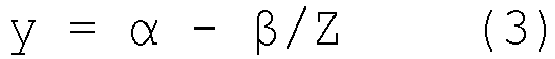
- When Expression (3) is converted into an expression for obtaining a Z value to calculate a Z value from the y coordinate on the
road surface 603, and x and y on theroad surface 603 and the Z value are applied to the expressions obtained by converting Expressions (1) and (2) to obtain X and Y, the coordinates (X, Y, Z) of a three-dimensional space corresponding to a point (x, y) of theobject 2104 on theroad surface 603 can be calculated. When the moving distance and the moving direction of the vehicle obtained from the difference between the y coordinate values of the left and right geometric correction table illustrated inFIG. 4 are added to the (X, Y, Z) and the (x, y) of the left camera image is obtained again by Expressions (1) and (2), it is possible to obtain an image in which the deviation between the exposure times of the geometrically transformedright image 2201 and the geometrically transformedleft image 2101 is corrected. - As described above, the time
difference calculation unit 601 of the exposure timedifference adjusting unit 60 illustrated inFIG. 1 compares the correction data (correction amount) indicated at the same coordinate position in the left and right geometric correction tables (the geometric correction table right 28 and the geometric correction table left 27) to obtain the difference, and multiplies (in consideration of) the time difference of the exposure timing per raster to obtain the deviation amount (exposure time difference) of the exposure timing between the same coordinates of the left and right geometrically corrected images. - In addition, as described above, the coordinate
adjustment unit 602 of the exposure timedifference adjusting unit 60 corrects the positional deviation of the image, in other words, adjusts the geometric correction position of the left image, using the deviation amount (exposure time difference) of the exposure timing and the vehicle information regarding the position or movement of the vehicle. The vehicle information includes a turning angle, an own vehicle speed, and the like, and is obtained from, for example, a steering angle, a yaw rate, and a speed sensor mounted on the vehicle. In addition, as the vehicle information, a turning angle, an own vehicle speed, and the like may be calculated from an own vehicle position. As a result, it is possible to calculate the moving distance and the moving direction of the vehicle that has moved in the deviation period of the exposure timing. -
FIG. 7 illustrates an operation flow of thestereo camera device 10. - First, images are captured by the
right camera 22 and the left camera 21 (S100). Next, the geometric transformation processing is performed to correct lens distortion of the image. For this purpose, the table reference coordinategeneration unit 80 updates the coordinates (x, y) to which the geometric correction table is referred (S110). The exposure timedifference adjusting unit 60 calculates reference coordinates (x', y') of the left image based on the exposure time difference between the left and right images (S120). Details of this portion will be described later based onFIG. 8 . Next, the geometric correction table right 28 for correction of the right image is accessed with coordinates (x, y), and the geometric correction table left 27 for correction of the left image is accessed with coordinates (x', y'). Using the results of accessing the respective geometric correction tables, the geometric correction (right)unit 26 and the geometric correction (left)unit 25 perform image correction processing as illustrated inFIG. 4 (S130). This correction processing is performed on the entire image (S140). - Next, using the geometrically corrected left and right images, the
parallax calculation unit 30 generates parallax data (S150). The roadsurface estimation unit 70 creates a road surface parameter (α, β) using the parallax data (S160). Using the parallax data, theobject detection unit 40 detects an object on the road surface, calculates a position, a distance, and a size of the object, and detects the road obstacle (S170). Then, thevehicle control unit 50 generates a control instruction for controlling the brake, the suspension, and the like according to the position of the road obstacle so as not to cause an obstacle in traveling of the own vehicle (S180), and then determines the ending of the system (S190). -
FIG. 8 illustrates a processing flow of the exposure time difference adjusting unit 60 (the processing flow of S120 inFIG. 7 described above). The left and right geometric correction tables are accessed in accordance with (x, y), and a difference s in the number of rasters is obtained from the difference between the correction coordinate values recorded in the left and right geometric correction tables as illustrated inFIG. 4 (S200). This s is indicated by a table indicating the deviation in exposure time (a difference in exposure timing for each pixel) with a time ratio in units of rasters. The exposure time difference r between the left and right cameras of the pixel of (x, y) is obtained (by the time difference calculation unit 601) from the difference s (S210). When the exposure time difference per raster of the image sensor is δ, the exposure time difference r is expressed by the following Expression (4).
(Math. 4)
- Subsequently, a distance w and a direction (u, v) in which the vehicle has moved during the period of the exposure time difference r are obtained based on vehicle information such as an own vehicle speed and a turning angle (S220). Next, the coordinates of the correction portion (x, y) of the left image are converted into (X, Y, Z) in a three-dimensional space using Expressions (1), (2), and (3) (S230). The (u, v, w) is added to the (X, Y, Z) and applied to Expressions (1) and (2) to obtain the position (x', y') on the image as follows (by the coordinate adjustment unit 602) (S240).
- (Math. 5)

- (Math. 6)

- The processing of S130 of
FIG. 7 is performed using this (x', y') as described above. - As described above, the
image processing device 20 of the first embodiment includes the geometric correction unit (the geometric correction (right)unit 26, the geometric correction (left) unit 25) that corrects the distortion of the images captured by the plurality of rolling shutter-type image sensors parallax calculation unit 30 that calculates the parallax using the corrected image corrected by the geometric correction unit, and the exposure timedifference adjusting unit 60 that adjusts the geometric correction position of at least one image (left image) based on the difference between the geometric correction amount (geometric correction table right 28) used for distortion correction of the image (right image) as a reference captured by thepixel sensor 220 and the geometric correction amount (geometric correction table left 27) used for distortion correction of the other image (left image) captured by thepixel sensor 210 and the vehicle information (own vehicle speed, turning angle, etc.) regarding the position or movement of the vehicle. - In addition, a geometric correction table (the geometric correction table right 28 and the geometric correction table left 27) as a geometric correction amount is included, and the exposure time
difference adjusting unit 60 obtains a difference in exposure timing for each pixel between the images from a difference in the correction amounts of the geometric correction table right 28 of the image (right image) serving as a reference and the geometric correction table left 27 of the other image (left image), and adjusts the geometric correction position of at least one image (left image) based on the difference in exposure timing for each pixel and the vehicle information. - As described above, in the first embodiment, the function of adjusting the deviation of the exposure timings of the left and right images is realized by adjusting the reference position (geometric correction position) of the geometric correction table used for the geometric correction processing of correcting the lens distortion of the left and right images. Specifically, in the
stereo camera device 10, a difference between the exposure timings of pixels at the same position is calculated for the left and right images after correcting the geometric distortion of the lens, the image is corrected in accordance with the distance and direction in which the vehicle has moved based on the difference, and the exposure timings of the pixels of the left and right images are matched. - As a result, according to the first embodiment, for example, in the
stereo camera device 10, pixels on the same raster of the respective images (left and right images) become images with the same exposure timing, and thus, there is an effect that an error in parallax calculation of the stereo matching processing can be reduced. In addition, it is not necessary to exclusively provide the image conversion processing for adjusting the deviation of the exposure timing, and as a result, it is possible to reduce the amount of hardware and the calculation load. -
FIG. 9 is a system configuration diagram of thestereo camera device 10 on which theimage processing device 20 including the exposure timedifference adjusting unit 60 that previously holds a time difference between exposure timings of pixels of left and right images as a table (exposure left table 605) in the second embodiment is mounted. The difference fromFIG. 1 is that the exposure timedifference adjusting unit 60 holds in advance a raster difference (for each pixel) of the same coordinate portion of the geometric correction table right 28 and the geometric correction table left 27 as the exposure difference table 605. The raster difference corresponds to s in Expression (4) described above. - The exposure time
difference adjusting unit 60 of theimage processing device 20 extracts the value of the exposure difference table 605 corresponding to the pixel to be adjusted (corresponding to the deviation amount of the exposure timing between the same coordinates of the left and right geometrically corrected images), and corrects the positional deviation of the image using the extracted value and the vehicle information regarding the position or movement of the vehicle, in other words, adjusts the geometric correction position of the left image. - As described above, the
image processing device 20 of the second embodiment includes the exposure difference table 605 indicating the difference in the exposure timing for each pixel between the images captured by therespective image sensors difference adjusting unit 60 extracts the value of the exposure difference table 605 corresponding to the pixel to be adjusted, and adjusts the geometric correction position of at least one image (left image) based on the extracted value and the vehicle information. - As described above, in the first embodiment illustrated in
FIG. 1 , s is calculated in each frame from the geometric correction table right 28 and the geometric correction table left 27, but in the second embodiment illustrated inFIG. 9 , the calculation of s can be omitted by the exposure difference table 605 to reduce the amount of calculation. - As a result, according to the second embodiment, it is possible to reduce the calculation load (of the exposure time difference adjusting unit 60) in the
image processing device 20 in addition to obtaining the same operation and effect as those of the first embodiment described above. - In the stereo camera device, in addition to the image deviation due to the distortion of the optical lens, the optical axis deviation of the left and right camera images may occur due to secular change or temperature change. Since a parameter of the distortion of the optical lens is determined when the lens is processed, the correction (distortion correction) is static geometric correction. On the other hand, in the correction of the optical axis deviation (amount) accompanying secular change or temperature change, a parameter is determined when the stereo camera device is used, and thus, the correction is dynamic geometric correction.
-
FIG. 10 is a system configuration diagram of thestereo camera device 10 on which theimage processing device 20 provided with a dynamicgeometric correction unit 90 according to a third embodiment is mounted. It is assumed that the dynamicgeometric correction unit 90 detects the amount of optical axis deviation of an image during operation due to secular change or temperature change by a method as disclosed in PTL 1 (JP 2018-105682 A unit 25, and processing of deviating the image captured by the left camera 21 in the longitudinal direction by an amount indicated by the amount of longitudinal deviation is performed. Alternatively, the amount of longitudinal deviation is sent to the geometric correction (right)unit 26, and processing of deviating the image captured by theright camera 22 in the longitudinal direction by an amount indicated by the amount of longitudinal deviation is performed. In addition, the exposure timedifference adjusting unit 60 adds (or subtracts) the amount of longitudinal deviation to the value of the exposure difference table 605 and calculates a final deviation amount of raster. Using this result, the exposure timedifference adjusting unit 60 calculates the reference coordinates of the geometric correction table left 27 in the same manner as in the first and second embodiments described above. - As described above, the
image processing device 20 of the third embodiment includes the dynamicgeometric correction unit 90 that detects the amount of optical axis deviation of the image in operation, and the exposure timedifference adjusting unit 60 adjusts the geometric correction position of at least one image (left image) using the deviation (difference) of the exposure timing of the image and (the amount of longitudinal deviation of the image corresponding to) the amount of optical axis deviation detected by the dynamicgeometric correction unit 90. - As described above, in the third embodiment, even when the
stereo camera device 10 has a deviation in the left and right camera images due to secular change or temperature change, the deviation of the exposure timing is corrected in consideration of the deviation, and the image is corrected based on the correction. - As a result, according to the third embodiment, it is possible to calculate more correct parallax data in addition to obtaining the same operational effects as those of the first and second embodiments described above.
-
FIG. 11 is a diagram illustrating an example of correcting the image of aroad sign 606 as an object other than an object on the road surface. In order to correct the image of the object, a distance Z is required in addition to the (x, y) on the image. The distance Z of the object at the road surface height can be obtained by the above Expression (3). However, the distance Z cannot be obtained for an object other than the road surface height by this method. Therefore, in the fourth embodiment, a method using parallax data will be described. -
FIG. 12 is a processing flowchart of theparallax calculation unit 30 that obtains the distance Z of an object by using parallax data. - First, the coordinates (x, y) of a portion to be corrected in the image are specified (S300). Thereafter, the location (x", y") of the (x, y) is searched for from the image one frame before (S310). Parallax data d of the coordinates of (x", y") is converted into a distance Z" by the following Expression (7) (S320). In Expression (7), f is a focal distance, B is a distance between the left and right cameras, and a is a size of one pixel of the image sensor.
(Math. 7)
- Next, the distance Z is obtained by adding a distance traveled by the own vehicle in one frame period to the distance Z" (S330). From the (x, y) and the Z, (X, Y) can be calculated by modifying Expressions (1) and (2) (S340). Then, in order to obtain an image in which the exposure timings are matched on the left and right sides, correction coordinates of the image can be calculated by Expressions (5) and (6).
- As described above, according to the method of the fourth embodiment, it is possible to also correct an object other than the object on the road surface to an image in which the exposure timings of the left and right images are matched.
- As a result, according to the fourth embodiment, it is possible to calculate correct parallax data in a wider range in addition to obtaining the same operational effects as those of the first to third embodiments described above.
- Note that, in the above-described embodiment, the
stereo camera device 10 includes two (left and right) cameras, but the number of cameras constituting thestereo camera device 10 may be three or more. - In addition, in the above-described embodiment, the camera (the left camera 21 and the right camera 22) including the image sensor constituting the
stereo camera device 10 and theimage processing device 20 are configured as separate bodies. However, the camera and a part (for example, the geometric correction (left)unit 25, the geometric correction (right)unit 26, the exposure timedifference adjusting unit 60, and the like) or the whole of theimage processing device 20 may be integrated, in other words, a part (for example, the geometric correction (left)unit 25, the geometric correction (right)unit 26, the exposure timedifference adjusting unit 60, and the like) or the whole of theimage processing device 20 may be incorporated in the camera. - Further, the present invention is not limited to the embodiments described above, but includes various modifications. For example, the above embodiments have been described in detail for easy understanding of the invention, and the invention is not necessarily limited to having all the configurations described. A part of the configuration of a certain embodiment can be replaced with the configuration of another embodiment, and the configuration of another embodiment can be added to the configuration of a certain embodiment. It is possible to add, delete, and replace other configurations for a part of the configuration of each embodiment.
- Each of the above configurations, functions, processing units, processing means, and the like may be partially or entirely achieved by hardware by, for example, designing by an integrated circuit. Each of the above configurations, functions, and the like may be achieved by software by a processor interpreting and executing a program that achieves each function. Information such as a program, a table, and a file for achieving each function can be stored in a memory device such as a memory, a hard disk, or a solidstate drive (SSD), or a recording medium such as an integrated circuit (IC) card, a secure digital (SD) card, or a digital versatile disc (DVD).
- In addition, only control lines and information lines considered to be necessary for explanation are illustrated, but not all the control lines and the information lines for a product are illustrated. In practice, almost all the configurations may be considered to be connected to each other.
-
- 10
- stereo camera device
- 20
- image processing device
- 21
- left camera
- 22
- right camera
- 23
- optical lens (left)
- 24
- optical lens (right)
- 25
- geometric correction (left) unit
- 26
- geometric correction (right) unit
- 27
- geometric correction table right
- 28
- geometric correction table left
- 30
- parallax calculation unit
- 40
- object detection unit
- 50
- vehicle control unit
- 60
- exposure time difference adjusting unit
- 70
- road surface estimation unit
- 80
- table reference coordinate generation unit
- 90
- dynamic geometric correction unit
- 210
- image sensor (left)
- 220
- image sensor (right)
- 601
- time difference calculation unit
- 602
- coordinate adjustment unit
- 603
- road surface
- 604
- vanishing point
- 605
- exposure difference table
- 606
- road sign
Claims (7)
- An image processing device comprising:a geometric correction unit configured to correct distortion of images captured by a plurality of rolling shutter-type image sensors mounted in a vehicle;a parallax calculation unit configured to calculate a parallax using a corrected image that is corrected by the geometric correction unit; andan exposure time difference adjusting unit configured to adjust a geometric correction position of at least one image based on a difference between a geometric correction amount used for distortion correction of an image serving as a reference and a geometric correction amount used for distortion correction of other images and vehicle information regarding a position or movement of the vehicle.
- The image processing device according to claim 1, comprisinga geometric correction table as a geometric correction amount used for distortion correction of an image captured by the image sensor, whereinthe exposure time difference adjusting unit obtains an exposure timing for each pixel between the images from a difference in correction amounts of the geometric correction table of the image serving as a reference and the geometric correction table of the other images, and adjusts a geometric correction position of at least one image based on the difference in the exposure timing for the each pixel and the vehicle information.
- The image processing device according to claim 1, comprisingan exposure difference table indicating a difference in an exposure timing for each pixel between the images captured by the respective image sensors, whereinthe exposure time difference adjusting unit extracts a value of the exposure difference table corresponding to an image to be adjusted, and adjusts a geometric correction position of at least one image based on the extracted value and the vehicle information.
- The image processing device according to claim 2, wherein a difference in the exposure timing for the each pixel is indicated by a table indicating a time ratio in units of rasters.
- The image processing device according to claim 1, wherein the vehicle information includes an own vehicle speed and a turning angle.
- The image processing device according to claim 1, comprisinga dynamic geometric correction unit configured to detect an amount of optical axis deviation of an image in operation, whereinthe exposure time difference adjusting unit adjusts a geometric correction position of at least one image using a deviation of the exposure timing of the image and the amount of optical axis deviation detected by the dynamic geometric correction unit.
- A stereo camera device comprising:the image processing device according to claim 1; andthe plurality of image sensors configured to input images to the image processing device.
Applications Claiming Priority (2)
| Application Number | Priority Date | Filing Date | Title |
|---|---|---|---|
| JP2019167079A JP7247063B2 (en) | 2019-09-13 | 2019-09-13 | Image processing device and stereo camera device using the same |
| PCT/JP2020/030857 WO2021049250A1 (en) | 2019-09-13 | 2020-08-14 | Image processing device and stereo camera device using same |
Publications (2)
| Publication Number | Publication Date |
|---|---|
| EP4030746A1 true EP4030746A1 (en) | 2022-07-20 |
| EP4030746A4 EP4030746A4 (en) | 2023-09-20 |
Family
ID=74862665
Family Applications (1)
| Application Number | Title | Priority Date | Filing Date |
|---|---|---|---|
| EP20862427.0A Pending EP4030746A4 (en) | 2019-09-13 | 2020-08-14 | Image processing device and stereo camera device using same |
Country Status (3)
| Country | Link |
|---|---|
| EP (1) | EP4030746A4 (en) |
| JP (1) | JP7247063B2 (en) |
| WO (1) | WO2021049250A1 (en) |
Family Cites Families (4)
| Publication number | Priority date | Publication date | Assignee | Title |
|---|---|---|---|---|
| JP2012198075A (en) * | 2011-03-18 | 2012-10-18 | Ricoh Co Ltd | Stereoscopic camera device and image adjusting method |
| JP6541590B2 (en) * | 2016-02-03 | 2019-07-10 | クラリオン株式会社 | Camera calibration device |
| JP6707022B2 (en) | 2016-12-26 | 2020-06-10 | 日立オートモティブシステムズ株式会社 | Stereo camera |
| JP6967464B2 (en) * | 2018-01-26 | 2021-11-17 | 日立Astemo株式会社 | Image processing device |
-
2019
- 2019-09-13 JP JP2019167079A patent/JP7247063B2/en active Active
-
2020
- 2020-08-14 EP EP20862427.0A patent/EP4030746A4/en active Pending
- 2020-08-14 WO PCT/JP2020/030857 patent/WO2021049250A1/en unknown
Also Published As
| Publication number | Publication date |
|---|---|
| JP7247063B2 (en) | 2023-03-28 |
| JP2021044764A (en) | 2021-03-18 |
| EP4030746A4 (en) | 2023-09-20 |
| WO2021049250A1 (en) | 2021-03-18 |
Similar Documents
| Publication | Publication Date | Title |
|---|---|---|
| EP3287985B1 (en) | Image processing device | |
| JP6167525B2 (en) | Distance measuring device and vehicle | |
| CN110023951B (en) | Information processing apparatus, image forming apparatus, device control system, information processing method, and computer-readable recording medium | |
| EP3070675B1 (en) | Image processor for correcting deviation of a coordinate in a photographed image at appropriate timing | |
| US10659762B2 (en) | Stereo camera | |
| JP2008039491A (en) | Stereo image processing apparatus | |
| JP6708730B2 (en) | Mobile | |
| KR20150101749A (en) | Device for estimating three-dimensional shape of object and method thereof | |
| JP6970577B2 (en) | Peripheral monitoring device and peripheral monitoring method | |
| EP3282389B1 (en) | Image processing apparatus, image capturing apparatus, moving body apparatus control system, image processing method, and program | |
| JP6035774B2 (en) | Image processing apparatus, image processing method, and vehicle | |
| US11509813B2 (en) | Image processing device | |
| JP6673160B2 (en) | Distance measuring device | |
| US10204400B2 (en) | Image processing apparatus, imaging apparatus, image processing method, and recording medium | |
| JP6844223B2 (en) | Information processing equipment, imaging equipment, equipment control system, information processing method and program | |
| EP4030746A1 (en) | Image processing device and stereo camera device using same | |
| EP3640585B1 (en) | Stereo camera device | |
| JP2014138331A (en) | Imaging apparatus and program | |
| JP2021033605A (en) | Image processor and method for processing image | |
| US10726528B2 (en) | Image processing apparatus and image processing method for image picked up by two cameras | |
| JP2018033035A (en) | Image processing apparatus, imaging device, program, instrument control system, and instrument | |
| JP6680335B2 (en) | Stereo camera, vehicle, calculation method and program | |
| JP7134780B2 (en) | stereo camera device | |
| JP6443502B2 (en) | Image processing apparatus, photographing apparatus, control system, moving object, and program | |
| JP6674127B2 (en) | Image processing device, photographing device, program, device control system and device |
Legal Events
| Date | Code | Title | Description |
|---|---|---|---|
| STAA | Information on the status of an ep patent application or granted ep patent |
Free format text: STATUS: THE INTERNATIONAL PUBLICATION HAS BEEN MADE |
|
| PUAI | Public reference made under article 153(3) epc to a published international application that has entered the european phase |
Free format text: ORIGINAL CODE: 0009012 |
|
| STAA | Information on the status of an ep patent application or granted ep patent |
Free format text: STATUS: REQUEST FOR EXAMINATION WAS MADE |
|
| 17P | Request for examination filed |
Effective date: 20220214 |
|
| AK | Designated contracting states |
Kind code of ref document: A1 Designated state(s): AL AT BE BG CH CY CZ DE DK EE ES FI FR GB GR HR HU IE IS IT LI LT LU LV MC MK MT NL NO PL PT RO RS SE SI SK SM TR |
|
| DAV | Request for validation of the european patent (deleted) | ||
| DAX | Request for extension of the european patent (deleted) | ||
| REG | Reference to a national code |
Ref country code: DE Ref legal event code: R079 Free format text: PREVIOUS MAIN CLASS: H04N0005232000 Ipc: H04N0013239000 |
|
| A4 | Supplementary search report drawn up and despatched |
Effective date: 20230822 |
|
| RIC1 | Information provided on ipc code assigned before grant |
Ipc: G01C 3/00 20060101ALI20230816BHEP Ipc: H04N 13/296 20180101ALI20230816BHEP Ipc: H04N 13/239 20180101AFI20230816BHEP |