JP6443502B2 - Image processing apparatus, photographing apparatus, control system, moving object, and program - Google Patents
Image processing apparatus, photographing apparatus, control system, moving object, and program Download PDFInfo
- Publication number
- JP6443502B2 JP6443502B2 JP2017124035A JP2017124035A JP6443502B2 JP 6443502 B2 JP6443502 B2 JP 6443502B2 JP 2017124035 A JP2017124035 A JP 2017124035A JP 2017124035 A JP2017124035 A JP 2017124035A JP 6443502 B2 JP6443502 B2 JP 6443502B2
- Authority
- JP
- Japan
- Prior art keywords
- image
- parallax
- correction amount
- unit
- correction
- Prior art date
- Legal status (The legal status is an assumption and is not a legal conclusion. Google has not performed a legal analysis and makes no representation as to the accuracy of the status listed.)
- Active
Links
Images


Description
本発明は、画像処理装置、撮影装置、制御システム、移動体、及びプログラムに関する。 The present invention relates to an image processing device, a photographing device, a control system, a moving object, and a program .
近年、車載用の距離計測装置が実用化されている。このような距離計測装置では、自動車に搭載されたステレオカメラにより車両前方を撮影し、撮影した画像から障害物を認識し、障害物までの距離を計測する。距離計測装置を自動車などの移動体に適用した場合には、距離計測装置からの計測結果に基づいて衝突防止のために運転者に警告を行ったり、或いは車間距離制御のためにブレーキ、ステアリングなどの制御装置の操作を行うといったことが可能になる。 In recent years, in-vehicle distance measuring devices have been put into practical use. In such a distance measuring device, the front of the vehicle is photographed by a stereo camera mounted on an automobile, an obstacle is recognized from the photographed image, and the distance to the obstacle is measured. When the distance measuring device is applied to a moving body such as an automobile, the driver is warned to prevent a collision based on the measurement result from the distance measuring device, or the brake, steering, etc. are used for controlling the distance between the vehicles. It is possible to operate the control device.
ここで、ステレオカメラを利用した距離計測の原理について説明する。
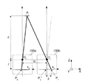
図10は、ステレオカメラを利用した距離計測の原理説明図である。
ステレオカメラは、例えば2台のカメラを平行に配置して構成される。図10には、焦点距離f、光学中心O0、撮像面S0の第1のカメラ100aが紙面上方を光軸方向として配置され、かつ、同じ焦点距離fを持つ第2のカメラ100bが、第1のカメラ100aの右側に距離Bだけ離れて平行に配置されている。
第1のカメラ100aの光学中心O0から光軸方向に距離dだけ離れた位置にある被写体Aの像は、直線A−O0と撮像面S0の交点であるP0に像を結ぶ。
Here, the principle of distance measurement using a stereo camera will be described.
FIG. 10 is a diagram illustrating the principle of distance measurement using a stereo camera.
A stereo camera is configured, for example, by arranging two cameras in parallel. In FIG. 10, a
The image of the subject A located at a distance d in the optical axis direction from the optical center O 0 of the
一方、第2のカメラ100bでは、同じ被写体Aが、撮像面S1上の位置P1に像を結ぶ。
ここで、第2のカメラ100bの光学中心O1を通り、直線A−O0と平行な直線と、撮像面S1との交点をP0’とし、P0’とP1の距離をpとする。P0’は、第1のカメラ100a上の像P0と同じ位置であり、距離pは、同じ被写体の像の二台のカメラで撮影した画像上での位置のずれ量を表し、これを視差と呼ぶ。
三角形A−O0−O1と、三角形O1−P0’−P1は相似なので、
d=B×f/p ・・・(1)
となり、基線長Bと焦点距離fが既知ならば、視差pから距離dを求めることができる。
On the other hand, the
Here, as the optical center O 1 of the
Since the triangle A-O 0 -O 1 and the triangle O 1 -P 0 ′ -P 1 are similar,
d = B × f / p (1)
If the base line length B and the focal length f are known, the distance d can be obtained from the parallax p.
以上が、ステレオカメラによる距離計測の原理である。
この原理が成立するためには、第1のカメラ100aと第2のカメラ100bは図10に示すように正確に配置されていなければならない。
しかしながら、2台のカメラを組み付ける際の公差を無くして厳密に平行配置することは非常に困難であるため、信号処理により補正する技術が各種提案されている。
The above is the principle of distance measurement using a stereo camera.
In order to establish this principle, the
However, since it is very difficult to eliminate the tolerance when assembling the two cameras and to arrange them strictly in parallel, various techniques for correcting by signal processing have been proposed.
例えば特許文献1には、ステレオカメラを組み立てた後、既知の位置にセットしたテストチャートを撮影することで、二台のカメラ間の相対的な配置関係を正確に計測し、その情報を利用して、撮影された画像データを変形することによって、擬似的に平行配置を実現する技術が開示されている。このとき、特許文献1では、画像データの変形として、アフィン変換を採用している。
また特許文献2には、結像レンズ系の歪曲収差など、アフィン変換だけでは対応しきれない、非線形なずれを補正するため、テーブルを利用する技術が開示されている。テーブルの内容は、既知の位置にセットしたテストチャートを撮影したデータを元に決定する。
特許文献3には、振動や温度変化などにより、実際の利用中に生じる初期状態からのずれに対応するための技術が開示されている。実際の利用中は、製造時のように既知のテストチャートを撮影することが困難なため、路面の白線の平行性だけを利用してずれ量を計測するようにしている。
For example, in
Patent Document 3 discloses a technique for dealing with a deviation from an initial state that occurs during actual use due to vibration or temperature change. During actual use, it is difficult to photograph a known test chart as at the time of manufacture, so the amount of deviation is measured using only the parallelism of the white lines on the road surface.
ところで、上記したような距離計測装置が高い精度を維持するには、正確なキャリブレーションが必要になる。このため、従来より様々なキャリブレーション技術が提案されている。
従来のキャリブレーション技術は、キャリブレーションを実行するタイミングと、画像変形の自由度の2種類に大別することができる。
さらにキャリブレーションを実行するタイミングは、製造時と利用時に分けることができる。例えば製造時におけるキャリブレーションでは、レンズの光学的な歪みや組み立て時のずれなどをカメラ製造時に計測して補正する。一方、利用時におけるキャリブレーションでは、温度変化や振動などによる経時変化の影響によるずれを利用中に計測して補正する。
また画像変形の自由度は、アフィン変換、非線形テーブル変換、平行移動(一定のオフセット)などがある。
By the way, in order for the distance measuring apparatus as described above to maintain high accuracy, accurate calibration is required. For this reason, various calibration techniques have been conventionally proposed.
Conventional calibration techniques can be broadly divided into two types: calibration execution timing and image deformation freedom.
Furthermore, the timing for executing calibration can be divided at the time of manufacture and at the time of use. For example, in calibration at the time of manufacturing, optical distortion of a lens, deviation at the time of assembly, and the like are measured and corrected at the time of camera manufacturing. On the other hand, in the calibration at the time of use, a shift due to the influence of a change with time due to temperature change or vibration is measured and corrected during use.
The degree of freedom of image deformation includes affine transformation, nonlinear table transformation, parallel movement (fixed offset), and the like.
しかしながら、利用時に行うキャリブレーションでは、例えばテストチャートなどの既知の被写体を撮影できないため、一定のオフセット以外の画像変換を行うことができなかった。このため、横方向の画像ずれ量を正確に計測することが困難であった。
これはステレオカメラを構成する2台のカメラが例えば組み立て時の公差等が無く理想的な平行状態で設置されている場合は、一方のカメラで撮影された左画像と他方のカメラで撮影された右画像の対応点は、必ず水平方向の視差を有するため、対応点間の位置差の垂直成分が存在すれば、その対応点間の位置差から縦方向の画像ずれが生じていることを容易に推定することができる。これに対して、横方向の視差については、その真値が被写体までの距離によるため、横方向のずれ量は検知が難しく容易に推定することができなかった。
However, in the calibration performed at the time of use, for example, since a known subject such as a test chart cannot be photographed, image conversion other than a certain offset cannot be performed. For this reason, it has been difficult to accurately measure the amount of lateral image shift.
This is because, when the two cameras that make up the stereo camera are installed in an ideal parallel state with no tolerance during assembly, for example, the left image taken with one camera and the other camera Since the corresponding point in the right image always has a horizontal parallax, if there is a vertical component of the positional difference between the corresponding points, it is easy to cause a vertical image shift from the positional difference between the corresponding points. Can be estimated. On the other hand, since the true value of the parallax in the horizontal direction depends on the distance to the subject, the amount of shift in the horizontal direction is difficult to detect and cannot be estimated easily.
また、特許文献3には、白線の平行性や、静止被写体の多さを利用して、視差オフセット、つまり左右画像の画面全体の横方向の平行移動量を推定するようにしているが、2台のカメラが平行配置されているステレオカメラの横方向の画像ずれは、平行移動とは限らないため、横方向の画像ずれを実際の利用中に既知のテストチャートなどを用いることなく計測して補正を行うことはできなかった。 In Patent Document 3, the parallelism of white lines and the number of still subjects are used to estimate the parallax offset, that is, the horizontal translation amount of the entire screen of the left and right images. Since the horizontal image shift of a stereo camera with two cameras arranged in parallel is not necessarily a parallel movement, measure the horizontal image shift without using a known test chart during actual use. Corrections could not be made.
ここで、ステレオカメラにおいて発生する横ずれの種類について説明する。
ステレオカメラにおいて発生する横ずれには、例えば、縦軸まわりの回転による横ずれと、歪曲特性の変化による横ずれがある。
縦軸まわりの回転による横ずれは、カメラの視線方向を上下左右に微小に変化させると、撮影画像の反対方向(下上右左)に移動する。しかし、このときの画像の移動は厳密には平行移動ではない。例えば、図11(a)に示すようにカメラ100が左方向に傾いた場合に、カメラに正対した長方形がどのように変形するかを図11(b)に示す。
図11(b)では特に強調して示してあるが、図11(a)に示すようにカメラ100が左方向に傾いた場合はカメラ100の撮影画像は長方形110から台形120に変形する。この場合、画面全体で画像は右方向にずれるが、画面左側は縮小され、より中央に近づくため、画面中心付近のB点に比べ、左端のA点は大きく右に動き、逆に画面右側は拡大され、より中央から離れるために、右端のC点もやはり大きく右に動く。その結果、画像の右方向へのずれ量は、図12に示すように、画面全体で均一ではない。
従来は、ずれの角度が微小であれば、図11(b)に示した台形120は長方形110に非常に近いため、近似的に平行移動とみなしていたが、より正確な視差検出のためには、単純な平行移動ではなく、画素位置に応じたずれ量が存在するものとして補正しなければならない。
Here, the types of lateral deviation that occur in a stereo camera will be described.
For example, the lateral shift generated in the stereo camera includes a lateral shift due to rotation around the vertical axis and a lateral shift due to a change in distortion characteristics.
The lateral shift due to the rotation around the vertical axis moves in the opposite direction (lower upper right and left) of the captured image when the line-of-sight direction of the camera is slightly changed up and down and left and right. However, the movement of the image at this time is not strictly a parallel movement. For example, FIG. 11B shows how a rectangle facing the camera is deformed when the
Although it is particularly emphasized in FIG. 11B, when the
Conventionally, if the angle of deviation is very small, the
次に、歪曲特性の変化による横ずれについて説明する。結像レンズ系は、一般に歪曲収差特性を有している。初期状態では特許文献2のようにテーブルを利用して、非線形なひずみを補正することもできるが、経時的に歪曲特性が変化する場合もある。その場合、例えば画面中心付近は変化が少ないが、周辺では拡大または縮小が生じるなど、平行移動以外の画像ずれが生じる。また、レンズの傾きや偏心など、光軸対称ではないずれがレンズ系に発生すれば、非等方的な歪曲が生じてさらに複雑なずれとなり得る。
このように従来の距離計測装置におけるキャリブレーション技術では、距離計測装置が実際に稼働している状態において、画像ずれ量を正確に計測して補正することはできないという問題点があった。
本発明は、上記したような点を鑑みてなされたものであり、一様でない画像ずれ量を考慮して、画素位置に応じた視差補正量を算出することを目的とする。
Next, a lateral shift due to a change in distortion characteristics will be described. The imaging lens system generally has distortion characteristics. In the initial state, a non-linear distortion can be corrected using a table as in
As described above, the conventional calibration technique in the distance measuring apparatus has a problem that the image shift amount cannot be accurately measured and corrected in a state where the distance measuring apparatus is actually operated.
The present invention has been made in view of the above points, and an object thereof is to calculate a parallax correction amount corresponding to a pixel position in consideration of a non-uniform image shift amount.
上記目的を達成するため、請求項1記載の発明は、移動体に搭載された第1撮影手段により撮影された第1画像において複数の特徴点を抽出する抽出手段と、前記第1画像および当該第1画像と同時に当該第1画像と異なる視点から前記移動体に搭載された第2撮影手段により撮影された第2画像を用いて、抽出された前記複数の特徴点に各々対応する複数の視差データを計算する視差計算手段と、第1の時刻において撮影された第1画像および第2画像についての複数の視差データの各々と、前記第1の時刻とは異なる第2の時刻において撮影された第1画像および第2画像についての複数の視差データの各々とを対応づけて、複数の視差データ対を特定する特定手段と、前記複数の視差データ対に各々対応する前記特徴点の画像位置に応じて、画像位置に応じた視差補正量を算出する補正量算出手段と、前記画像位置に応じた視差補正量で、前記画像位置に応じて補正を行う視差補正手段と、を備えることを特徴とする。
In order to achieve the above object, the invention according to
本発明によれば、画素位置に応じた視差補正量を算出することができる。 According to the present invention, it is possible to calculate a parallax correction amount corresponding to a pixel position.
以下、本発明の実施形態に係る距離計測装置について説明する。
<第1実施形態>
図1は、本発明の第1実施形態に係る距離計測装置のハードウェア全体の構成を示したブロック図である。
図1に示す本実施形態の距離計測装置1は、左カメラ11aと右カメラ11bとを平行に配したステレオカメラ(画像撮像手段)11と視差計算部(視差算出手段)20とにより構成される。
左カメラ11a、右カメラ11bは、異なる視点からそれぞれ画像を撮影する。
視差計算部20は、左カメラ11a、右カメラ11bにより撮影された画像が入力され、視差画像データを出力する。
視差計算部20は、バス接続されたCPU(Central Processing Unit)、DRAM(Dynamic Random Access Memory)メモリ、不揮発性フラッシュメモリなどを備えた一般的な電子計算機により構成される。視差計算機能は、フラッシュメモリに記録され、CPU、DRAMなどを利用して実行されるソフトウェアプログラムの形態で実装される。
なお、本実施形態では、ステレオカメラ11が二台のカメラ11a、11bを備えている場合を例に挙げて説明したが、これはあくまでも一例であり、三台以上のカメラを用いて構成しても良いことは言うまでもない。
Hereinafter, a distance measuring device according to an embodiment of the present invention will be described.
<First Embodiment>
FIG. 1 is a block diagram showing the overall hardware configuration of the distance measuring apparatus according to the first embodiment of the present invention.
A
The left camera 11a and the
The
The
In the present embodiment, the case where the stereo camera 11 includes two
図2は、図1に示す視差計算部20で実行されるソフトウェアモジュール全体のブロック図である。
カメラ制御部21は、左カメラ11aと右カメラ11bとを制御し、画像データの入力を行う。また、2台のカメラ同期、カメラ初期化、露光制御などを実行する。ここでは説明しないが、必要に応じ、光学系による歪曲、画像回転など、一般的にステレオ距離計測に有効とされる視差オフセット以外の画像補正処理を、入力直後に施すことが望ましい。また、カメラ制御部21は、左右2台のカメラで同時に撮影した2枚の画像を次々に出力する。
ここでは、右カメラ11bで撮影した撮影画像を基準画像、左カメラ11aで撮影した撮影画像を参照画像と呼ぶ。
視差画像生成処理部22は、カメラ制御部21から入力される基準画像と参照画像の2枚の画像データから、画素ごとに視差を算出して補正前視差画像を生成する。なお、視差画像生成処理部22の詳細については後述する。
FIG. 2 is a block diagram of the entire software module executed by the
The
Here, a captured image captured by the
The parallax image
視差補正量算出処理部(推定手段)23は、例えば領域ごとの視差補正量を算出する領域視差補正量算出処理部23aとしての機能を有する。そして、カメラ制御部21から入力される基準画像、および視差画像生成処理部22から入力される補正前視差画像を利用して、X座標ごとの視差補正量を算出する。つまり、X座標=iの視差補正量をoff(i)として、画面幅の画素数分の[i,off(i)]のテーブル情報を生成する。算出した視差補正量は、視差補正処理部24に送られ、視差画像補正処理に利用される。なお、領域視差補正量算出処理部23aの詳細については後述する。
視差補正処理部(補正手段)24は、視差画像の各画素の視差値から、視差補正量算出処理部23から入力した補正量のうち、画素位置に対応する補正量を減算することにより、視差画像データを補正する。つまり、入力される視差画像中の、画素位置(i,j)の視差値をd(i,j)、X座標=iの視差補正量をoff(i)とすると、O(i,j)=d(i,j)−off(i)を補正視差値として出力する。
The parallax correction amount calculation processing unit (estimating unit) 23 has a function as, for example, a region parallax correction amount
The parallax correction processing unit (correction unit) 24 subtracts the correction amount corresponding to the pixel position from the correction amount input from the parallax correction amount
次に、図3に示すフローチャートを参照して、視差画像生成処理部22の処理動作を説明する。
ステップS1では、ステレオ画像を入力する。すなわち、平行配置された2台のカメラで同時に撮影された画像を入力する。続くステップS2は、特徴点を抽出する。
ステップS3では、対応点の探索を行う。すなわち、まず基準となる右カメラ11bにおいて撮影された基準画像から濃淡変化の激しい特徴点を複数抽出する。次に反対の左カメラ11aにおいて撮影された参照画像から、基準画像上の各特徴点近傍領域(ブロック)と同じ被写体の写った対応点の位置を探索する。対応点探索には、SAD(Sum of Absolute Difference)やPOC(位相限定相関)など周知の技術を利用することができる。
ステップS4では、視差を算出する。すなわち、対応点探索処理で算出した左右画像上の対応点位置の差分を取り、視差を算出する。
ステップS5では、視差画像を出力する。すなわち、算出された視差量を画素値とする視差画像データ(視差情報)を出力する。
以上の処理を定期的に繰返し実行することで、常にカメラ前方の視差画像を出力し続ける。
Next, the processing operation of the parallax image
In step S1, a stereo image is input. That is, images taken simultaneously by two cameras arranged in parallel are input. In the subsequent step S2, feature points are extracted.
In step S3, a corresponding point is searched. That is, first, a plurality of feature points having a sharp change in density are extracted from a reference image taken by the
In step S4, the parallax is calculated. That is, the difference between the corresponding point positions on the left and right images calculated by the corresponding point search process is taken to calculate the parallax.
In step S5, a parallax image is output. That is, parallax image data (parallax information) having the calculated parallax amount as a pixel value is output.
By periodically executing the above processing, the parallax image in front of the camera is always output.
次に、領域視差補正量算出処理部23aについて説明する。
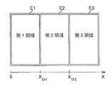
領域視差補正量算出処理部23aは、領域ごとの視差オフセット算出処理として、2回のステレオ撮影間での同じ被写体(特徴点)の視差データ対の集合に基づき、視差オフセットを算出する。但し、1枚目の基準画像上での特徴点の位置が、図4の3つの領域(第1領域E1、第2領域E2、第3領域E3)のいずれに属するかによって、視差データ対を3つの集合に分類する。つまり、図4のように、第1領域E1と第2領域E2の境界のX座標値をXth1、第2領域E2、第3領域E3の境界をXth2、特徴点の座標値を(X、Y)とすると、
X<Xth1となる特徴点は集合1に、
X>Xth2となる特徴点は集合3に、
それ以外は集合2と判定する。
それぞれの集合に対して独立に統計処理を実行して、領域ごとに3つの視差オフセット量を推定する。
ここで、いずれかの領域に属する特徴点数が、予め決められた閾値よりも少なければ、その領域の視差オフセット推定は行わず、前フレームまでの推定結果をそのまま採用する。
Next, the regional parallax correction amount
The area parallax correction amount
Feature points satisfying X <X th1 are in
Feature points satisfying X> X th2 are in set 3,
Otherwise, it is determined as
Statistical processing is performed on each set independently to estimate three parallax offset amounts for each region.
Here, if the number of feature points belonging to any region is smaller than a predetermined threshold, the estimation result up to the previous frame is used as it is without performing the parallax offset estimation for that region.
次に、X座標ごとの視差補正量算出処理について説明する。
第1領域E1、第2領域E2、第3領域E3の中心のX座標をそれぞれX1、X2、X3と呼ぶ。
上記の第1領域E1〜第3領域E3ごとの視差オフセット算出ステップの結果を、X座標=X1、X2、X3の3点での補正量とみなし、これらの線形補間によって、すべてのX座標での補正量を算出する。つまり、X<X2の範囲の補正量を、X1とX2での視差オフセットの線形補間で求め、またX2<Xの範囲の補正量をX2とX3での視差オフセットの線形補間で求める。このように求めた1画素ごと画像幅分の(X座標、補正量)のテーブルを、視差補正処理部24へ出力する。
Next, the parallax correction amount calculation process for each X coordinate will be described.
The X coordinates of the centers of the first region E1, the second region E2, and the third region E3 are referred to as X 1 , X 2 , and X 3 , respectively.
The result of the parallax offset calculation step for each of the first region E1 to the third region E3 is regarded as a correction amount at three points of X coordinates = X 1 , X 2 , X 3 , A correction amount at the X coordinate is calculated. That is, the correction amount in the range of X <X 2 is obtained by linear interpolation of the parallax offset in X 1 and X 2 , and the correction amount in the range of X 2 <X is linear in the parallax offset in X 2 and X 3 Find by interpolation. A table of (X coordinate, correction amount) corresponding to the image width for each pixel thus obtained is output to the parallax
図5は、第1実施形態による視差補正量の計算例を示す図である。
横軸がX座標、縦軸が視差補正量を表す。図中、白丸が3領域ごとの視差オフセット(=視差補正量)を、実線Aが、線形補間によって得られる全X座標での補正量を表す。
また図5では、図12に示した理想的な補正量を破線Bで、従来のような一定の視差オフセットを利用する場合を一点鎖線Cで示してある。図5から本実施形態による補正量(実線A)のほうが、従来の一定値(一点鎖線C)より理想量(破線B)に近い場合が多くなることがわかる。
第1実施形態では、領域分割として図4に示す横方向3分割を採用したが、これはあくまでも一例であり、カメラの経時変化の特性に応じて設定すればよい。例えば、分割数の増減や縦横2次元分割も可能であり、領域間に隙間やオーバーラップなどを設けることも可能ある。
また、第1実施形態では、視差補正量算出処理部23の一例として、複数の領域ごとに視差補正量の算出を行う領域視差補正量算出処理部23aを例に挙げて説明したが、これはあくまでも一例であり、視差補正量算出処理部23は他の構成でもよい。
FIG. 5 is a diagram illustrating a calculation example of the parallax correction amount according to the first embodiment.
The horizontal axis represents the X coordinate, and the vertical axis represents the parallax correction amount. In the figure, white circles represent parallax offsets (= parallax correction amounts) for every three regions, and solid line A represents a correction amount for all X coordinates obtained by linear interpolation.
In FIG. 5, the ideal correction amount shown in FIG. 12 is indicated by a broken line B, and a case where a constant parallax offset as in the conventional case is used is indicated by a one-dot chain line C. FIG. 5 shows that the correction amount (solid line A) according to the present embodiment is closer to the ideal amount (dashed line B) than the conventional constant value (dashed line C).
In the first embodiment, the horizontal division shown in FIG. 4 is adopted as the area division. However, this is merely an example, and may be set in accordance with the characteristics of the camera over time. For example, the number of divisions can be increased or decreased and vertical and horizontal two-dimensional division can be performed, and gaps or overlaps can be provided between regions.
In the first embodiment, as an example of the parallax correction amount
また第1実施形態では、画素位置に応じた補正量としてX座標1画素ごとの補正量テーブルを採用したが、多項式や折れ線、スプラインなど、X座標−補正量空間での線を表現する他の形式のデータを利用することもできる。
また第1実施形態は、視差補正量算出処理を2フレームごとに実行するようにしているが、信頼性評価をして信頼性の低いフレームの情報を棄却したり、フレーム蓄積を行い、より精度や安定性を向上させることもできる。
このように、第1実施形態の距離計測装置1では、2台のカメラ11a、11bを使用して、二つの地点(時刻)から撮影した2枚の視差画像間での、同じ被写体(特徴点)に関する二つの視差データの対を多数収集する。そして、領域視差補正量算出処理部23aにおいて、その視差データ対の集合を統計処理することで視差オフセットを計測する。
特徴点は元々画面上の特定の位置を占めているので、第1実施形態では視差データ対を、特徴点の位置に応じて分類することにより、画像領域ごとの視差オフセットを検出するようにしている。
In the first embodiment, the correction amount table for each pixel of the X coordinate is adopted as the correction amount according to the pixel position. However, other expressions for expressing a line in the X coordinate-correction amount space such as a polynomial, a broken line, and a spline are used. Format data can also be used.
In the first embodiment, the parallax correction amount calculation process is performed every two frames. However, the reliability evaluation is performed to reject information on frames with low reliability, or frame accumulation is performed to obtain more accuracy. And stability can be improved.
Thus, in the
Since the feature points originally occupy a specific position on the screen, in the first embodiment, the parallax data pairs for each image area are detected by classifying the parallax data pairs according to the positions of the feature points. Yes.
例えば、図4に示すように、画面全体を左から第1領域E1、第2領域E2、第3領域E3に三分割し、撮影画像上で特徴点が3つのどの領域に属していたかに応じて、視差データ対を3つの集合に分類する。それぞれの集合に対して、統計処理を施すことにより、領域視差補正量算出処理部23aにおいて、それぞれの画像領域での視差オフセット量を推定することができる。
正確には、この方法で推定できるのは、図11、図12に示したような撮影画像のずれ量そのものではなく、2枚の撮影画像間の視差の変化量である。視差は被写体距離に応じて変わるため、これは2枚の画像の同位置のずれ量の差分とも一致はしない。しかし、ずれ量の変化が図12のように画素位置に対してゆるやかに変化し、また、対象とする視差がその変化率に対して小さい場合(例えば、画面幅の1/20以下の視差を扱う場合)、視差オフセットは2枚の画像のずれ量の差分とみなすことができる。
さらに、微小な画像ずれは視差が小さいほど大きな影響を及ぼす。例えば、0.5画素のずれは、100画素の視差に対しては0.5%の誤差にしかあたらないが、1画素の視差に対しては50%の誤差となる。
For example, as shown in FIG. 4, the entire screen is divided into a first area E1, a second area E2, and a third area E3 from the left, depending on which area the three feature points belong to on the captured image. Thus, the parallax data pairs are classified into three sets. By performing statistical processing on each set, the region parallax correction amount
Exactly, what can be estimated by this method is not the amount of deviation of the captured image itself as shown in FIGS. 11 and 12, but the amount of change in parallax between the two captured images. Since the parallax changes according to the subject distance, this does not coincide with the difference in the shift amount at the same position of the two images. However, when the change in the shift amount changes gradually with respect to the pixel position as shown in FIG. 12, and the target parallax is small with respect to the change rate (for example, a parallax of 1/20 or less of the screen width). In the case of handling), the parallax offset can be regarded as a difference between the shift amounts of the two images.
Furthermore, the smaller the image shift, the greater the effect of the smaller the parallax. For example, a shift of 0.5 pixels is only an error of 0.5% for a parallax of 100 pixels, but an error of 50% for a parallax of 1 pixel.
そこで、第1実施形態では、この画素位置に応じた視差オフセット量を2枚の画像ずれ量の差とみなし、これを利用して補正手段である視差補正処理部24において視差データ(視差情報)を補正するようにした。
これにより、一様でない横方向の画像ずれを、利用中に例えばテストチャートなどの既知の被写体を用いることなく補正することができるので、より正確な視差画像を生成することができる。
Therefore, in the first embodiment, the parallax offset amount corresponding to the pixel position is regarded as a difference between the two image shift amounts, and the parallax
As a result, a non-uniform lateral image shift can be corrected without using a known subject such as a test chart during use, so that a more accurate parallax image can be generated.
また第1実施形態では、視差生成処理部(対応点位置差算出手段)22において、複数の画像間の対応点を探索し、対応点間の座標の差分である視差データを算出する。そして、視差補正処理部(視差補正手段)24において、視差データを視差補正量算出処理部(推定手段)23からの補正量に基づいて補正するようにしているので、単純な演算によって、画素位置に応じた画素横ずれを補正することができるという利点がある。
因みに、従来の特許文献1のような路面の白線に基づく方法では、路面の白線が写る画像領域全体での平均的な視差オフセット量しか計測しかできない。そして自動車の前方に向け設置されたカメラに路面の白線が写る位置は、いつも画面下半分あたりで変化しないため、領域ごとのオフセット計測を行うことができない。これに対して、本実施形態では、特徴点ベースの統計処理による視差オフセット計測方法を利用することで、領域ごとのオフセット計測が実現できるものである。
In the first embodiment, the parallax generation processing unit (corresponding point position difference calculating unit) 22 searches for corresponding points between a plurality of images, and calculates parallax data that is a difference in coordinates between the corresponding points. Since the parallax correction processing unit (parallax correction unit) 24 corrects the parallax data based on the correction amount from the parallax correction amount calculation processing unit (estimation unit) 23, the pixel position is calculated by a simple calculation. There is an advantage that the pixel lateral shift corresponding to can be corrected.
Incidentally, in the conventional method based on the white line on the road surface as in
<第2実施形態>
次に本発明の第2実施形態について説明する。
第1実施形態では視差データを補正したが、第2実施形態では視差画像生成に利用する参照画像を補正する。この場合は、歪曲や組み立て誤差などを補正するための画像補正処理が存在するならば、その段階に補正処理を組み込むことにより、視差画像の補正という後処理が不要になる。
なお、第2実施形態の全体構成及びハードウェア構成は、図1に示した第1実施形態と同様であるため、説明は省略する。以下、ソフトウェア処理内容の第1実施形態との差異部分を重点的に説明する。
Second Embodiment
Next, a second embodiment of the present invention will be described.
In the first embodiment, the parallax data is corrected, but in the second embodiment, the reference image used for generating the parallax image is corrected. In this case, if there is an image correction process for correcting distortion, assembly error, and the like, the post-processing of correcting the parallax image becomes unnecessary by incorporating the correction process at that stage.
The overall configuration and hardware configuration of the second embodiment are the same as those of the first embodiment shown in FIG. Hereinafter, differences from the first embodiment of the software processing contents will be mainly described.
図6は、視差計算部20で実行されるソフトウェアモジュール全体のブロック図である。なお、図2と同一ブロックには、同一符号を付して説明は省略する。
図6に示すカメラ制御部21は、第1実施形態と同様に2台のカメラを制御し、基準画像、参照画像を出力する。
基準画像補正処理部31は、カメラ製造時に計測したずれや歪曲特性に応じて画像を変形補正する。
FIG. 6 is a block diagram of the entire software module executed by the
The
The reference image
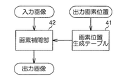
図7は、基準画像補正処理部31の内部ブロック構成を示した図である。
一般に画像の変形処理とは、出力画像のすべての画素位置について、対応する入力画像上の画素位置を算出する画素位置生成テーブル(座標生成処理部)41と、算出された画素位置に対応する入力画像上の画素値を算出する画素補間部42とから構成される。なお、画素値は必ずしも整数値とは限らない。
第2実施形態では、全画素分のXY座標を予めテーブルとして記録しておき、それを参照することで入力画像上の画素位置を生成する。テーブルは、カメラ製造時に既知の位置に設置したテストチャートを撮影し、特徴点間を補間して生成し、カメラ内部に記録しておく。なお、第2実施形態ではテーブルを利用するが、多項式演算などによる座標変換など、テーブル以外の方法で画素位置を生成することもできる。
画像補正量算出処理部32は、上記視差補正量算出処理部23と同様であり、図4に示したように画像領域を分割して、それぞれの領域ごとに視差オフセットを求め、それらを補間して全画素分の補正量を出力する。但し、第2実施形態では画像補正量算出処理部32が出力する補正量を画像補正に利用する。
参照画像補正処理部(画像補正手段)33は、基準画像補正処理部31と同様に画像を変形して補正する。但し、基準画像はカメラ製造時に計測したずれ特性に基づいて補正したが、参照画像の補正では、予め計測、記録された特性に加え、画像補正量算出処理部32で算出された利用時に発生したずれも補正する。
FIG. 7 is a diagram illustrating an internal block configuration of the reference image
In general, the image transformation process includes a pixel position generation table (coordinate generation processing unit) 41 that calculates pixel positions on the corresponding input image for all pixel positions of the output image, and an input corresponding to the calculated pixel position. The
In the second embodiment, XY coordinates for all pixels are recorded in advance as a table, and the pixel position on the input image is generated by referring to the table. The table is generated by photographing a test chart placed at a known position at the time of camera manufacture, interpolating between feature points, and recording it inside the camera. In the second embodiment, a table is used, but the pixel position can also be generated by a method other than the table, such as coordinate conversion by polynomial calculation.
The image correction amount
The reference image correction processing unit (image correction unit) 33 deforms and corrects an image in the same manner as the standard image
図8に参照画像補正処理部33の内部ブロック図を示す。
参照画像補正処理部33は、画素位置生成テーブル41、画素補間部42、画素位置補正処理部43とを備えている。なお、図7と同一ブロックには同一符号を付して説明は省略する。
画素位置生成テーブル41のテーブル内容は、上記同様、カメラ製造時に計測して記録しておく。
画素位置補正処理部43は、画像補正量算出処理部32から入力するX座標ごとの画像補正量を使い、テーブルに記録された画素位置データを補正する。
具体的には、テーブルから読み出した座標(X、Y)のX座標に対して、X座標に対応する補正量off(i)を加算して出力する。これにより、視差が大きすぎる場合、すなわち、基準画像と比べ右側にくる場合は、参照画像を左側に移動するよう変形されるので、後で算出される視差を小さくすることができる。なお、X座標が整数でない場合は、例えば四捨五入で整数化すれば良い。
FIG. 8 shows an internal block diagram of the reference image
The reference image
The table contents of the pixel position generation table 41 are measured and recorded when the camera is manufactured, as described above.
The pixel position
Specifically, the correction amount off (i) corresponding to the X coordinate is added to the X coordinate of the coordinates (X, Y) read from the table and output. Thereby, when the parallax is too large, that is, when the parallax is on the right side compared to the base image, the reference image is deformed to move to the left side, so that the parallax calculated later can be reduced. When the X coordinate is not an integer, it may be converted to an integer by rounding off, for example.
視差画像生成処理部22は、補正された基準画像、参照画像を入力し、第1実施形態と同様の処理により、視差画像を生成する。入力される参照画像は、すでに画像補正量算出処理によって算出された、視差オフセット分だけ横方向にずらしてあるため、視差オフセット分のノイズが低減される。
なお、第2実施形態では、参照画像の補正だけに画像補正量算出処理部32の結果を反映したが、逆に基準画像側の補正に反映したり、補正量を基準画像と参照画像に分配することもできる。つまり、参照画像補正処理部33だけでなく、基準画像補正処理部31、或いは参照画像補正処理部33と基準画像補正処理部31の両方を画像補正手段として機能させるようにしてもよい。
The parallax image
In the second embodiment, the result of the image correction amount
このように、第2実施形態では、画素位置に応じた視差オフセット量を2枚の画像ずれ量の差とみなし、これを利用して参照画像を補正するようにしている。
これにより、一様でない横方向の画像ずれを、稼動中に例えばテストチャートなどの既知の被写体を用いることなく補正することができるようになる。
また第2実施形態では、参照画像補正処理部33において、画像補正量算出処理部32から補正量に基づいて参照画像を補正する。そして、視差画像生成処理部22において補正した参照画像と基準画像間の対応点を探索し、対応点間の座標の差分である視差データを算出するようにしているので、単純な演算によって、画素位置に応じた画素横ずれを補正することができるという利点がある。
As described above, in the second embodiment, the parallax offset amount corresponding to the pixel position is regarded as the difference between the two image shift amounts, and the reference image is corrected using this difference.
This makes it possible to correct non-uniform lateral image shifts without using a known subject such as a test chart during operation.
In the second embodiment, the reference image
<その他の実施形態>
図10は、本実施形態の距離計測装置1が適用される画像処理システムと、その画像処理システムが搭載された車両の模式図である。
図10に示す画像処理システムは、車両前方の画像を取得するための撮像ユニット51と、取得した画像に基づいて車両50の前方に存在する他の車両までの距離を算出する等の処理を行う画像解析ユニット52を有している。撮像ユニット51は、車両50が走行する前方の画像を撮像できるように、座席のルームミラー位置等に設置されている。撮像ユニット51で撮像された車両前方の画像は、画像信号化されて画像解析ユニット52に入力される。画像解析ユニット52は、撮像ユニット51から出力された画像信号を解析する。
撮像ユニット51として、上記実施形態のステレオカメラ11を適用できる。
また、画像解析ユニット52の一部の機能として、上記実施形態の視差計算部20を適用することが出来る。
車両走行制御ユニット53は、画像解析ユニット52で計算された距離に基づいてハンドルやブレーキの制御も行うことが出来る。
<Other embodiments>
FIG. 10 is a schematic diagram of an image processing system to which the
The image processing system shown in FIG. 10 performs processing such as calculating the distance to an
As the
Further, as a part of the function of the image analysis unit 52, the
The vehicle
11…ステレオカメラ、11a…左カメラ、11b…右カメラ、20…視差計算部、21…カメラ制御部、22…視差画像生成処理部、23…視差補正量算出処理部、24…視差補正処理部、31…基準画像補正処理部、32…画像補正量算出処理部、33…参照画像補正処理部、41…画素位置生成テーブル、42…画素補間部、43…画素位置補正処理部
DESCRIPTION OF SYMBOLS 11 ... Stereo camera, 11a ... Left camera, 11b ... Right camera, 20 ... Parallax calculation part, 21 ... Camera control part, 22 ... Parallax image generation process part, 23 ... Parallax correction amount calculation process part, 24 ... Parallax correction process part Reference image
Claims (8)
前記第1画像および当該第1画像と同時に当該第1画像と異なる視点から前記移動体に搭載された第2撮影手段により撮影された第2画像を用いて、抽出された前記複数の特徴点に各々対応する複数の視差データを計算する視差計算手段と、
第1の時刻において撮影された第1画像および第2画像についての複数の視差データの各々と、前記第1の時刻とは異なる第2の時刻において撮影された第1画像および第2画像についての複数の視差データの各々とを対応づけて、複数の視差データ対を特定する特定手段と、
前記複数の視差データ対に各々対応する前記特徴点の画像位置に応じて、画像位置に応じた視差補正量を算出する補正量算出手段と、
前記画像位置に応じた視差補正量で、前記画像位置に応じて補正を行う視差補正手段と、
を備えることを特徴とする画像処理装置。 Extracting means for extracting a plurality of feature points in the first image photographed by the first photographing means mounted on the moving body ;
The plurality of feature points extracted by using the second image taken by the second photographing unit mounted on the moving body from a different viewpoint from the first image and the first image simultaneously with the first image. Parallax calculation means for calculating a plurality of corresponding parallax data,
Each of the plurality of parallax data regarding the first image and the second image captured at the first time, and the first image and the second image captured at a second time different from the first time A specifying means for associating each of the plurality of parallax data and specifying a plurality of parallax data pairs;
In accordance with the image position of the feature point, each corresponding to the plurality of parallax data pairs, a correction amount calculation means for calculating the parallax correction amount corresponding to the image position,
Parallax correction means for performing correction according to the image position with a parallax correction amount according to the image position;
An image processing apparatus comprising:
前記視差補正手段は、前記対応点位置差算出手段により算出された対応点位置差を、前記視差補正量に基づいて補正することを特徴とする請求項1又は2に記載の画像処理装置。 A corresponding point position difference calculating unit that searches for corresponding points between a plurality of captured images and calculates a difference in coordinates between the corresponding points is provided.
The image processing apparatus according to claim 1 , wherein the parallax correction unit corrects the corresponding point position difference calculated by the corresponding point position difference calculation unit based on the parallax correction amount.
前記第2画像を撮影する第2撮影手段と、
請求項1乃至4のいずれか1項に記載の画像処理装置と、を備えることを特徴とする撮影装置。 First photographing means for photographing the first image;
A second photographing means for photographing the second image;
Photographing apparatus characterized by comprising an image processing apparatus according to any one of claims 1 to 4.
前記画像処理装置により計算された視差データに基づいて制御を行う制御部と、を備えることを特徴とする制御システム。 An imaging device according to claim 5;
Control system characterized in that it comprises a control unit that performs control based on the disparity data calculated by the image processing apparatus.
前記制御部により制御されることを特徴とする移動体。 A control system according to claim 6,
A moving body controlled by the control unit.
移動体に搭載された第1撮影手段により所定の時刻に撮影された第1画像において複数の特徴点を抽出する抽出手段と、
前記第1画像および当該第1画像と同時刻において前記移動体に搭載された第2撮影手段により撮影された第2画像を用いて、抽出された前記複数の特徴点に各々対応する複数の視差データを計算する視差計算手段と、
第1の時刻において撮影された前記第1画像および前記第2画像についての複数の視差データの各々と、前記第1の時刻とは異なる第2の時刻において撮影された前記第1画像および前記第2画像についての複数の視差データの各々とを対応づけて、複数の視差データ対を特定する特定手段と、
前記複数の視差データ対に各々対応する前記特徴点の画像位置に応じて、画像位置に応じた視差補正量を算出する補正量算出手段と、
前記画像位置に応じた視差補正量で、前記画像位置に応じて補正を行う視差補正手段と、
を備える画像処理装置として機能させるプログラム。 Computer
Extracting means for extracting a plurality of feature points in the first image photographed at a predetermined time by the first photographing means mounted on the moving body ;
A plurality of parallaxes respectively corresponding to the plurality of feature points extracted using the first image and a second image photographed by a second photographing means mounted on the moving body at the same time as the first image. Disparity calculating means for calculating data;
Each of the plurality of parallax data regarding the first image and the second image captured at a first time, and the first image and the first image captured at a second time different from the first time A specifying unit that associates each of a plurality of parallax data for two images and specifies a plurality of parallax data pairs;
In accordance with the image position of the feature point, each corresponding to the plurality of parallax data pairs, a correction amount calculation means for calculating the parallax correction amount corresponding to the image position,
Parallax correction means for performing correction according to the image position with a parallax correction amount according to the image position;
A program for causing an image processing apparatus to function.
Applications Claiming Priority (2)
| Application Number | Priority Date | Filing Date | Title |
|---|---|---|---|
| JP2012063705 | 2012-03-21 | ||
| JP2012063705 | 2012-03-21 |
Related Parent Applications (1)
| Application Number | Title | Priority Date | Filing Date |
|---|---|---|---|
| JP2013003413A Division JP6167525B2 (en) | 2012-03-21 | 2013-01-11 | Distance measuring device and vehicle |
Publications (2)
| Publication Number | Publication Date |
|---|---|
| JP2017173343A JP2017173343A (en) | 2017-09-28 |
| JP6443502B2 true JP6443502B2 (en) | 2018-12-26 |
Family
ID=59970951
Family Applications (1)
| Application Number | Title | Priority Date | Filing Date |
|---|---|---|---|
| JP2017124035A Active JP6443502B2 (en) | 2012-03-21 | 2017-06-26 | Image processing apparatus, photographing apparatus, control system, moving object, and program |
Country Status (1)
| Country | Link |
|---|---|
| JP (1) | JP6443502B2 (en) |
Families Citing this family (1)
| Publication number | Priority date | Publication date | Assignee | Title |
|---|---|---|---|---|
| JP7321947B2 (en) * | 2020-01-20 | 2023-08-07 | 日立Astemo株式会社 | Image correction device and image correction method |
Family Cites Families (7)
| Publication number | Priority date | Publication date | Assignee | Title |
|---|---|---|---|---|
| JP3147002B2 (en) * | 1996-09-26 | 2001-03-19 | 富士電機株式会社 | Correction method of distance detection value |
| JP3436074B2 (en) * | 1997-06-10 | 2003-08-11 | トヨタ自動車株式会社 | Car stereo camera |
| JP2001033211A (en) * | 1999-07-23 | 2001-02-09 | Matsushita Electric Ind Co Ltd | Measuring method and device of three-dimensional data |
| JP3261115B2 (en) * | 1999-09-22 | 2002-02-25 | 富士重工業株式会社 | Stereo image processing device |
| JP5234894B2 (en) * | 2007-06-28 | 2013-07-10 | 富士重工業株式会社 | Stereo image processing device |
| JP5280768B2 (en) * | 2008-08-18 | 2013-09-04 | 本田技研工業株式会社 | Vehicle periphery monitoring device |
| JP2009075124A (en) * | 2008-11-06 | 2009-04-09 | Honda Motor Co Ltd | Distance detector |
-
2017
- 2017-06-26 JP JP2017124035A patent/JP6443502B2/en active Active
Also Published As
| Publication number | Publication date |
|---|---|
| JP2017173343A (en) | 2017-09-28 |
Similar Documents
| Publication | Publication Date | Title |
|---|---|---|
| JP6167525B2 (en) | Distance measuring device and vehicle | |
| JP5468426B2 (en) | Stereo camera device | |
| JP6035774B2 (en) | Image processing apparatus, image processing method, and vehicle | |
| JP6599685B2 (en) | Image processing apparatus and error determination method | |
| JP2008039491A (en) | Stereo image processing apparatus | |
| JP2007263669A (en) | Three-dimensional coordinates acquisition system | |
| JP6592991B2 (en) | Object detection apparatus, object detection method, and program | |
| JP6306735B2 (en) | Stereo camera device and vehicle equipped with stereo camera device | |
| JP2015194487A (en) | Disparity deriving apparatus, movable apparatus, robot, method of deriving disparity, method of producing disparity, and program | |
| JP2014074632A (en) | Calibration apparatus of in-vehicle stereo camera and calibration method | |
| JP6040782B2 (en) | Image processing apparatus and program | |
| JP6543935B2 (en) | PARALLEL VALUE DERIVING DEVICE, DEVICE CONTROL SYSTEM, MOBILE OBJECT, ROBOT, PARALLEL VALUE DERIVING METHOD, AND PROGRAM | |
| JP6443502B2 (en) | Image processing apparatus, photographing apparatus, control system, moving object, and program | |
| JP7303064B2 (en) | Image processing device and image processing method | |
| JP2018088217A (en) | Information processing device, imaging device, apparatus control system, information processing method, and program | |
| JP2014138331A (en) | Imaging apparatus and program | |
| JP2021051347A (en) | Distance image generation apparatus and distance image generation method | |
| JP6747176B2 (en) | Image processing device, photographing device, program, device control system and device | |
| JP6459487B2 (en) | Image processing apparatus, image processing method, and program | |
| JP2018146495A (en) | Object detection apparatus, object detection method, object detection program, imaging apparatus, and equipment control system | |
| KR102479253B1 (en) | Method for compensating camera tolerance based on a camera image of a vehicle | |
| JP7247063B2 (en) | Image processing device and stereo camera device using the same | |
| CN113424021B (en) | Image processing apparatus and method | |
| JP2019158759A (en) | Imaging apparatus, vehicle, and imaging method | |
| JP7206602B2 (en) | Imaging device, vehicle, and imaging method |
Legal Events
| Date | Code | Title | Description |
|---|---|---|---|
| A521 | Written amendment |
Free format text: JAPANESE INTERMEDIATE CODE: A523 Effective date: 20170726 |
|
| A621 | Written request for application examination |
Free format text: JAPANESE INTERMEDIATE CODE: A621 Effective date: 20170726 |
|
| A977 | Report on retrieval |
Free format text: JAPANESE INTERMEDIATE CODE: A971007 Effective date: 20180530 |
|
| A131 | Notification of reasons for refusal |
Free format text: JAPANESE INTERMEDIATE CODE: A131 Effective date: 20180605 |
|
| A521 | Written amendment |
Free format text: JAPANESE INTERMEDIATE CODE: A523 Effective date: 20180802 |
|
| TRDD | Decision of grant or rejection written | ||
| A01 | Written decision to grant a patent or to grant a registration (utility model) |
Free format text: JAPANESE INTERMEDIATE CODE: A01 Effective date: 20181030 |
|
| A61 | First payment of annual fees (during grant procedure) |
Free format text: JAPANESE INTERMEDIATE CODE: A61 Effective date: 20181112 |
|
| R151 | Written notification of patent or utility model registration |
Ref document number: 6443502 Country of ref document: JP Free format text: JAPANESE INTERMEDIATE CODE: R151 |