EP4030260A1 - Driving assistance apparatus - Google Patents
Driving assistance apparatus Download PDFInfo
- Publication number
- EP4030260A1 EP4030260A1 EP21215415.7A EP21215415A EP4030260A1 EP 4030260 A1 EP4030260 A1 EP 4030260A1 EP 21215415 A EP21215415 A EP 21215415A EP 4030260 A1 EP4030260 A1 EP 4030260A1
- Authority
- EP
- European Patent Office
- Prior art keywords
- elbow rest
- vehicle
- driver
- driving assistance
- assistance apparatus
- Prior art date
- Legal status (The legal status is an assumption and is not a legal conclusion. Google has not performed a legal analysis and makes no representation as to the accuracy of the status listed.)
- Pending
Links
Images



Classifications
-
- B—PERFORMING OPERATIONS; TRANSPORTING
- B60—VEHICLES IN GENERAL
- B60N—SEATS SPECIALLY ADAPTED FOR VEHICLES; VEHICLE PASSENGER ACCOMMODATION NOT OTHERWISE PROVIDED FOR
- B60N2/00—Seats specially adapted for vehicles; Arrangement or mounting of seats in vehicles
- B60N2/75—Arm-rests
- B60N2/787—Arm-rests detachable
-
- B—PERFORMING OPERATIONS; TRANSPORTING
- B60—VEHICLES IN GENERAL
- B60T—VEHICLE BRAKE CONTROL SYSTEMS OR PARTS THEREOF; BRAKE CONTROL SYSTEMS OR PARTS THEREOF, IN GENERAL; ARRANGEMENT OF BRAKING ELEMENTS ON VEHICLES IN GENERAL; PORTABLE DEVICES FOR PREVENTING UNWANTED MOVEMENT OF VEHICLES; VEHICLE MODIFICATIONS TO FACILITATE COOLING OF BRAKES
- B60T7/00—Brake-action initiating means
- B60T7/02—Brake-action initiating means for personal initiation
- B60T7/08—Brake-action initiating means for personal initiation hand actuated
-
- G—PHYSICS
- G05—CONTROLLING; REGULATING
- G05G—CONTROL DEVICES OR SYSTEMS INSOFAR AS CHARACTERISED BY MECHANICAL FEATURES ONLY
- G05G1/00—Controlling members, e.g. knobs or handles; Assemblies or arrangements thereof; Indicating position of controlling members
- G05G1/02—Controlling members for hand actuation by linear movement, e.g. push buttons
-
- G—PHYSICS
- G05—CONTROLLING; REGULATING
- G05G—CONTROL DEVICES OR SYSTEMS INSOFAR AS CHARACTERISED BY MECHANICAL FEATURES ONLY
- G05G1/00—Controlling members, e.g. knobs or handles; Assemblies or arrangements thereof; Indicating position of controlling members
- G05G1/02—Controlling members for hand actuation by linear movement, e.g. push buttons
- G05G1/025—Controlling members for hand actuation by linear movement, e.g. push buttons actuated by sliding movement
-
- G—PHYSICS
- G05—CONTROLLING; REGULATING
- G05G—CONTROL DEVICES OR SYSTEMS INSOFAR AS CHARACTERISED BY MECHANICAL FEATURES ONLY
- G05G1/00—Controlling members, e.g. knobs or handles; Assemblies or arrangements thereof; Indicating position of controlling members
- G05G1/58—Rests or guides for relevant parts of the operator's body
- G05G1/62—Arm rests
-
- G—PHYSICS
- G05—CONTROLLING; REGULATING
- G05G—CONTROL DEVICES OR SYSTEMS INSOFAR AS CHARACTERISED BY MECHANICAL FEATURES ONLY
- G05G1/00—Controlling members, e.g. knobs or handles; Assemblies or arrangements thereof; Indicating position of controlling members
- G05G1/01—Arrangements of two or more controlling members with respect to one another
Definitions
- the present invention relates to a driving assistance apparatus for physically handicapped people, and relates to a driving assistance apparatus that allows a person with a lower limb disability seated on a driver seat to manually perform a brake operation using a brake operation portion included in a vehicle cabin.
- a vehicle including an operation lever that allows a manual brake operation has been conventionally known (for example, see JP 2002 - 120 590 A ).
- a driver uses both of his or her upper arm and forearm during the brake operation to perform the operation using his or her shoulder as a pivot; accordingly, in a scene in which a fine brake operation state is held, it is difficult to hold a pushing amount of the arm constant, and there is a concern that a delicate brake operation cannot be performed.
- the inventors of the present invention have focused on a difference between the manual brake operation and the brake operation using the foot brake described above and have conducted earnest studies for a structure that allows a driver to easily manually perform a delicate brake operation.
- An object of the present invention is to provide a driving assistance apparatus that allows even a physically disabled driver to freely perform a driving operation and easily manually perform a delicate brake operation.
- a driving assistance apparatus including, in a vehicle cabin, a brake operation portion that allows a manual brake operation, the brake operation portion including a grip portion, and the apparatus is characterized in that an elbow rest member is provided at, in the vehicle rear side of the grip portion, a position on which an elbow portion of a driver can abut in a state in which the driver grips the grip portion so as to be capable of operating the grip portion.
- the brake operation is performed by placing the self-weight of an upper arm of the driver on the elbow rest member and adjusting the angle of his or her forearm using his or her elbow supported by the elbow rest member as a pivot, so that it is not necessary to move the whole arm, and accordingly it is possible to delicately control the braking force with the forearm.
- an elbow rest face of the elbow rest member may be provided toward the driver side in the vehicle width direction, and the elbow rest face may be provided inclined so as to be located on the driver side as it goes downward.
- an elbow rest member body of the elbow rest member is inclined so as to be located on a vehicle rear side as it goes upward.
- At least a part of an elbow rest face of the elbow rest member may be provided above an armrest provided in a center console of a vehicle.
- the driver can perform the brake operation while holding an appropriate driving posture without leaning against the center console side as in the case of placing the forearm on the armrest.
- At least a part of the elbow rest face is provided at a position on the vehicle front side from the armrest.
- the elbow rest member may be formed so as to be capable of being mounted on a cup holder provided in a center console of a vehicle.
- the elbow rest member comprises an elbow rest member body, wherein a lower portion of the elbow rest member body is disposed so as to overlap with at least a part of the grip portion in a vehicle width direction.
- a face of the elbow rest member body in a vehicle width direction is formed as an elbow rest face.
- the elbow rest member comprises an elbow rest member body, a vehicle body mounting portion and a support frame arranged between the elbow rest member body and the vehicle body mounting portion.
- the vehicle body mounting portion has an outer diameter being formed larger than an inner diameter of a cup holder provided in a center console of a vehicle.
- the vehicle body mounting portion includes a core material, preferably a metal, integrally formed with the support frame.
- an exterior member is externally provided on the core material.
- the exterior member is formed of an elastic member and is attached to an outer periphery of the core material.
- the exterior member forms the outer diameter of the vehicle body mounting portion.
- the elbow rest member body is formed in a parallelogram shape in a vehicle side view.
- each of corner portions of the elbow rest member body is formed in a chamfered shape.
- an upper portion of the driving assistance apparatus includes a brake operation unit, and a lower portion of the driving assistance apparatus includes an operation amount transmission unit.
- the driving assistance apparatus is configured such that the operation amount transmission unit intervenes between the brake operation unit and a brake pedal of a vehicle and is configured to transmit to the brake pedal an operation force of a sliding displacement of the grip portion preferably in a front-lower direction of the vehicle.
- the grip portion is biased to a neutral position.
- the neutral position of the grip portion and a neutral position of the brake pedal are associated with each other.
- the driving assistance apparatus comprises an accelerator manual operation apparatus including an accelerator lever being disposed in a vicinity of a radially inner side with respect to a rim portion of a steering wheel.
- a vehicle comprising the driving assistance apparatus according to any of claims 1 to 13.
- the vehicle comprises a brake pedal being configured to operate in conjunction with a sliding movement of the grip portion preferably in an axis direction of the steering wheel.
- arrow F indicates the vehicle front side
- arrow U the vehicle upper side
- arrow R the vehicle right side
- arrow L the vehicle left side
- arrow X the axis direction of a steering wheel
- arrow Xu the upper side of the axis direction of the steering wheel (driver side)
- arrow Xd the lower side of the axis direction of the steering wheel (the opposite side of the driver side).
- a vehicle of the present embodiment is a right-hand drive vehicle and includes a brake manual operation apparatus 10 that allows a driver with a lower limb disability who has difficulty in a depression operation of a brake pedal or an accelerator pedal with his or her foot to manually perform a brake operation in a state of being seated on a driver seat 8, and an accelerator manual operation apparatus 30 (see FIGS. 2 and 4 ) that allows the driver to manually perform an acceleration operation in a state of being seated on the driver seat 8.
- the brake manual operation apparatus 10 of the present embodiment corresponds to a driving assistance apparatus of the present invention.
- the brake manual operation apparatus 10 and the accelerator manual operation apparatus 30 are incorporated into a base vehicle by modifying the base vehicle.
- the brake manual operation apparatus 10 and the accelerator manual operation apparatus 30 will be described hereinafter, but prior to that, a description will be given of a schematic structure of the base vehicle.
- the driver seat 8 and a passenger seat 3 are mounted on the respective right and left sides of a front portion of a floor panel 2 (see FIG. 3 ) of a vehicle cabin in the vehicle, and as illustrated in FIGS. 2 and 4 , a steering wheel 6 that is operated in a state of being gripped by a driver seated on the driver seat 8 is provided in front of the driver seat 8.
- the steering wheel 6 includes a paddle shift switch formed by a pair of a shift-up switch for upshift and a shift-down switch for downshift.
- the shift-up switch is included on a rear face of a right-side spoke portion 6a
- the shift-down switch is included on a rear face of a left-side spoke portion 6b (illustration omitted).
- an instrument panel 80 is provided in a front end of the vehicle cabin over the whole vehicle width direction of the vehicle cabin.
- a center console 85 extending in the front-rear direction is provided between the driver seat 8 and the passenger seat 3 in the front portion of the floor panel 2 of the vehicle cabin.
- the instrument panel 80 and the center console 85 both form a part of an interior member of the vehicle cabin, and a front portion of the center console 85 is integrally connected to a vehicle-width-direction center portion of the instrument panel 80.
- various operation portions such as a shift knob 86 for a gear-shifting operation and a start switch 87, cup holders 88a and 88b (see FIG. 2 ), and an armrest 90 are provided in this order from the front side to the rear side.
- each of the cup holders 88a and 88b is formed in a recess shape such that a drink container can be placed thereon, and includes a lid 89 that opens and closes an opening thereof.
- the cup holder 88b for an occupant seated on the passenger seat 3 and the cup holder 88a for the driver are disposed in parallel on the respective left and right sides in an intermediate region between the various operation portions and the armrest 90 in the front-rear direction on the upper face of the center console 85.
- FIG. 2 illustrates only the lid 89 included in the cup holder 88b for the occupant.
- the intermediate region on the upper face of the center console 85 is not limited to being formed in a recess shape as the cup holders 88a and 88b as in the present embodiment and, for example, may be formed in a recess shape as a box portion that houses small items.
- a display portion 81 of various measurement instruments such as a tachometer and a speed meter is disposed in front of the driver seat 8 in the instrument panel 80 so as to be visible through the steering wheel 6, an air conditioning outlet 82 is disposed above a connection portion of the left side of the display portion 81 and the front portion of the center console 85, and a display 84 of a navigation device is provided below the air conditioning outlet 82.
- an accelerator pedal (illustration omitted) is provided at a position at which a right foot of the driver seated on the driver seat 8 is placed, on the floor panel 2 in front of the driver seat 8 in the vehicle cabin, and a brake pedal (illustration omitted) is provided near the left side from the accelerator pedal (vehicle-width-direction center side).
- the accelerator pedal is an organ-type pedal that operates a throttle valve of an engine
- the brake pedal is a suspended-type pedal that operates a brake, both of which are typical pedals included in the base vehicle.
- the brake manual operation apparatus 10 is installed on the left side with respect to the steering wheel 6 in the vicinity of the front side of the driver seat 8, that is, in the vicinity of a right wall 85a (see FIG. 3 ) of a connection portion of the center console 85 and the instrument panel 80.
- an upper portion of the brake manual operation apparatus 10 includes a brake operation unit 11, and a lower portion of the brake manual operation apparatus 10 includes an operation amount transmission unit 12. Furthermore, as illustrated in FIGS. 1 to 4 , the brake operation unit 11 includes an operation bar 13 and an axially supporting portion 14.
- the operation bar 13 is made of a metal pipe material (a so-called round pipe) having a circular orthogonal cross-section in the axis direction and is disposed in a posture inclined in a front-low rear-high shape. Specifically, an upper portion of the operation bar 13 is located at a height at which the driver seated on the driver seat 8 can operate the operation bar 13 with his or her left hand, at a position in the vicinity of the left side with respect to the steering wheel 6 (see FIG. 2 ) . Furthermore, as illustrated in FIGS. 1 and 3 , the operation bar 13 extends in the front-lower direction toward the floor panel 2 in the vicinity of the front side of the driver seat 8.
- a metal pipe material a so-called round pipe
- a lower portion of the operation bar 13 is axially supported by the axially supporting portion 14 such that the operation bar 13 is slidably displaced in the front-lower direction with respect to the axially supporting portion 14 by being subjected to a pushing operation (that is, a brake operation) in the front-lower direction along the axis direction of the operation bar 13.
- a pushing operation that is, a brake operation
- the operation bar 13 slides in the axis direction between a neutral position and a maximum pushing position at which the operation bar 13 is further pushed from the neutral position by a predetermined length in the front-lower direction. Note that the operation bar 13 illustrated in FIGS. 1 to 4 illustrates a state of being disposed in the neutral position.
- the operation amount transmission unit 12 intervenes between the brake operation unit 11 and the brake pedal (illustration omitted) and is configured to transmit to the brake pedal an operation force (operation amount) of the sliding displacement of the operation bar 13 in the front-lower direction. That is, the brake pedal included in the base vehicle is configured to operate in conjunction with sliding movement of the operation bar 13 in the axis direction due to the manual brake operation.
- the brake manual operation apparatus 10 can activate the brake by rotating the brake pedal at a depression amount according to a sliding amount (pushing amount) of the operation bar 13 in the front-lower direction during the manual brake operation using the operation bar 13.
- the operation bar 13 is biased to the neutral position, and the neutral positions of the operation bar 13 and the brake pedal are associated with each other.
- the operation bar 13 and the brake pedal are simultaneously restored to the respective neutral positions.
- the operation bar 13 included in the brake manual operation apparatus 10 of the present embodiment is formed by integrating an operation bar body 15 and a grip portion 16 provided at an upper end of the operation bar body 15.
- the operation bar body 15 is integrally formed having a base portion 15a and an inclined portion 15c linearly extending so as to be inclined to the vehicle-width-direction outer side as it goes upward, via a bent portion 15b from an upper end of the base portion 15a.
- the base portion 15a extends in a direction coinciding with the front-rear direction in a vehicle plan view, linearly extends in a posture inclined in a front-low rear-high shape coaxially with the axially supporting portion 14, and is formed with the same diameter along the axis direction.
- a lower portion of the base portion 15a is axially supported in a state of being fitted in the axially supporting portion 14 through an opening open toward the rear upper side of the axially supporting portion 14 in a tubular shape.
- the inclined portion 15c is inclined in a front-low rear-high shape similarly to the base portion 15a, while the inclined portion 15c is inclined in the front-low rear-high shape in a steeper posture (rising posture) than the base portion 15a and, as described above, extends so as to be inclined to the vehicle-width-direction outer side as it goes upward.
- the inclined portion 15c supports the grip portion 16 from therebelow in a manual operation region (a position corresponding to a boundary portion between the center console 85 and the floor panel 2 in a plan view) (see FIG. 2 ).
- the inclined portion 15c has a lower end formed with the substantially same diameter as the base portion 15a, and is formed in a tapered shape as it goes upward.
- a plurality of operation buttons for the driver to perform various operations while gripping the grip portion 16 are disposed on the grip portion 16.
- a brake lock switch 17 and a hazard switch 18 are disposed on a right-side face 16a of the grip portion 16.
- the brake lock switch 17 can lock and hold a brake state when the brake is in an activated state. That is, the brake lock switch 17 is pressed in a state in which the operation bar 13 for the brake operation is pushed down, and thereby can hold the operation bar 13 in the pushed down state. The brake lock switch 17 is pressed again and thereby can release the brake state.
- the hazard switch 18 can blink a hazard lamp (emergency blinking lamp) by being pressed by the driver and thereby can alert people around the vehicle and notify them of danger.
- a hazard lamp electronic blinking lamp
- the hazard switch 18 is configured to stop the blinking of the hazard lamp by being pressed again.
- a paddle shift switch 23 is provided on a front lower face 16d of the grip portion 16 (a back face on the non-driver side). Note that, although illustration is omitted, the paddle shift switch 23 is a seesaw-type switch in which a shift-down switch for shift-down and a shift-up switch for shift-up are disposed side by side in a pair.
- the accelerator manual operation apparatus 30 of the present embodiment includes an accelerator lever 31 as an acceleration operation member disposed in the vicinity of the radially inner side with respect to a rim portion 61 of the steering wheel 6.
- the accelerator lever 31 is configured to be capable of being pushed downward in the steering axis direction (non-driver side) from a neutral position by the driver using, for example, a thumb of his or her hand gripping the steering wheel 6. Furthermore, the accelerator lever 31 is biased to the neutral position (upward) so as to be capable of being restored to the neutral position from a position at which the accelerator lever 31 is pushed from the neutral position.
- the driver can perform a pushing operation of the accelerator lever 31 between the neutral position and a maximum pushing position at which the accelerator lever 31 is pushed by a predetermined length, and according to the pushing amount, the driver can perform an opening operation of the throttle valve of the engine, that is, an acceleration and deceleration operation of the vehicle.
- an elbow rest member 40 that allows abutment of the elbow portion is provided.
- the elbow rest member 40 is provided in a protruding manner at a position corresponding to the cup holder 88a for the driver in the center console 85 (that is, a position near the driver side in the vehicle width direction of the center console 85).
- the elbow rest member 40 is formed having an elbow rest member body 41, a support frame 42, and a vehicle body mounting portion 43.
- the vehicle body mounting portion 43 includes a core material (illustration omitted) integrally formed with the support frame 42, an exterior member 44 externally provided on the core material, and a trim panel 45 installed on an upper face of the exterior member 44.
- the core material although illustration is omitted, is formed of a metal frame forming a framework of the vehicle body mounting portion 43, or the like.
- the support frame 42 described later is extended downward to a section corresponding to the vehicle body mounting portion 43, and this downward extended portion is the core material for the vehicle body mounting portion 43 (illustration omitted).
- the exterior member 44 is formed of an elastic member such as urethane and is attached to mainly an outer periphery of the core material.
- the diameter of the vehicle body mounting portion 43 is formed slightly larger than the inner diameter of the cup holder 88a in a recess shape.
- the length of the vehicle body mounting portion 43 in the up-down direction is formed shorter than the depth of the cup holder 88a.
- the trim panel 45 (dummy lid) is formed in a plate shape having a size corresponding to the lid (illustration omitted) included in the cup holder 88a for the driver.
- the lid of the cup holder 88a for the driver is removed to bring the cup holder 88a into an open state, and as indicated by a white arrow in FIG. 5 , the vehicle body mounting portion 43 is fitted in the recess cup holder 88a through the opening, so that the vehicle body mounting portion 43 is fitted and held in the cup holder 88a.
- the trim panel 45 is in a state of being installed at a position corresponding to the lid of the cup holder 88a for the driver before the elbow rest member 40 is mounted on the vehicle body.
- the elbow rest member 40 can be removed from the vehicle body by withdrawing the vehicle body mounting portion 43 from the cup holder 88a, and the cup holder 88a is restored to a recess form such that a drink container can be placed thereon.
- the support frame 42 is provided in a protruding manner from a position corresponding to the cup holder 88a for the driver.
- the whole support frame 42 except for an upper portion thereof extends in the up-down direction (vertical direction), and as illustrated in FIGS. 1 , 3 , and 5 , the upper portion of the support frame 42 is provided inclined so as to be located rearward as it goes upward.
- the support frame 42 has an upper end portion mounted on a lower portion of the elbow rest member body 41 and supports the elbow rest member body 41 from immediately thereunder (see FIG. 7 ).
- the elbow rest member body 41 is formed in a plate shape including a frame (illustration omitted), a cushion pad, and a trim cover 47 covering the frame and the cushion pad (illustration omitted), and one face (right face) of the elbow rest member body 41 is disposed so as to substantially face the driver (driver seat 8) in the vehicle width direction.
- the frame is made of a metal material or a relatively hard resin material and forms a framework of the elbow rest member body 41.
- the cushion pad is made of, for example, a foamed material such as a flexible urethane foam and is assembled to the frame while covering at least a right face of the frame (a face on the side substantially facing the driver).
- the trim cover 47 is made of, for example, a skin material such as leather (natural leather, synthetic leather) or fabric (knit, woven fabric, non-woven fabric), has a right face skin disposed on the right face of the elbow rest member body 41, a left face skin disposed on a left face of the elbow rest member body 41, and a gusset skin connecting the right face skin and the left face skin, and is formed by suturing these skins.
- a skin material such as leather (natural leather, synthetic leather) or fabric (knit, woven fabric, non-woven fabric)
- the right face of the elbow rest member body 41 in the vehicle width direction is formed as an elbow rest face 48.
- the elbow rest face 48 secures flexibility by the cushion pad covering the right face of the frame, so as not to hurt the driver when abutting on his or her elbow.
- the elbow rest member body 41 is supported by the support frame 42 in a posture in which the elbow rest face 48 is inclined so as to be located on the driver (driver seat 8) side in the vehicle width direction as it goes downward.
- the elbow rest face 48 is inclined at an inclination angle of about 35 degrees with respect to the vertical direction in a vehicle front view such that the upper side thereof is located on the passenger seat 3 side and the lower side thereof is located on the driver seat 8 side.
- the inclination angle of the elbow rest face 48 can be set to any angle at which an elbow portion of a left arm of the driver easily abuts on the elbow rest face 48 in a state in which the driver grips the grip portion 16.
- the elbow rest member body 41 is disposed at a position in the vicinity of the left side of a seat portion of the driver seat 8 in a plan view, and the lower portion of the elbow rest member body 41 is disposed so as to overlap with at least a part of the grip portion 16 in the vehicle width direction.
- the elbow rest member body 41 is disposed at a position on the slightly left side with respect to the grip portion 16.
- the armrest 90 is installed on the rear side of the elbow rest member body 41, and as illustrated in FIG. 3 , the whole elbow rest member body 41 except for the lower portion thereof in the up-down direction is formed higher so as to project upward from an upper face of the armrest 90. Only an upper portion of the elbow rest member body 41 is disposed at the substantially same (overlapping in the up-down direction) height as the grip portion 16 (see FIG. 3 ).
- the elbow rest member body 41 is inclined so as to be located on the vehicle rear side as it goes upward, and is formed in a substantially parallelogram shape in which each of corner portions thereof is formed in a chamfered shape in a vehicle side view.
- a lower side 41d of the elbow rest member body 41 is linearly formed substantially horizontally in the vehicle front-rear direction, and as illustrated in FIGS. 5 and 6 , a rear side 41r and a front side 41f are both inclined so as to be located on the vehicle rear side as they go upward, and linearly extend in parallel to each other.
- the brake manual operation apparatus 10 (driving assistance apparatus) of the above-described embodiment includes, in the vehicle cabin, the operation bar 13 (brake operation portion) that allows the manual brake operation, and is characterized in that the operation bar 13 includes the grip portion 16, and as illustrated in FIGS. 1 to 3 , the elbow rest member 40 is provided at, in the vehicle rear side of the grip portion 16, a position on which the elbow portion of the driver can abut in a state in which the driver grips the grip portion 16 so as to be capable of operating the operation bar 13.
- the brake operation is performed by placing the self-weight of an upper arm of the driver on the elbow rest member body 41 in the elbow rest member 40 and adjusting the angle of his or her forearm using the elbow supported by the elbow rest member body 41 as a pivot, so that it is not necessary to move the whole left arm, and accordingly it is possible to delicately control the braking force with the forearm.
- the driver during the brake operation using the operation bar 13, even a physically disabled driver does not need to lose his or her posture and can maintain a comfortable driving posture, and thus, for example, the driver also can easily manually perform a steering operation, an acceleration operation, a shift change operation, and the like and consequently can freely perform a driving operation.
- the driver Dm pushes the operation bar 13 in the front-lower direction using the elbow of his or her left arm hitting against the elbow rest face 48 of the elbow rest member body 41 as a starting point.
- an armpit opening is suppressed in any sides in a front view and side view of the driver Dm, and the driver Dm can push his or her forearm while maintaining a comfortable driving posture without losing the driving posture.
- the driver Dm pushes the forearm in the front-lower direction by pushing the operation bar 13 with his or her left hand
- the operation track of the left hand in the front-lower direction during the brake operation can be assisted by the elbow rest member body 41, and consequently unnecessary movement such as a wobble of the left hand of the driver Dm is suppressed, enabling operations and control of the operation bar 13 with a lesser loss.
- the elbow rest face 48 of the elbow rest member body 41 is provided toward the driver side in the vehicle width direction, and the elbow rest face 48 is provided inclined so as to be located on the driver side as it goes downward.
- the elbow rest face 48 of the elbow rest member body 41 is provided inclined so as to be located on (approach) the driver side as it goes downward, and thus, as indicated by a solid line in FIG. 8 , in the case where the physique of the driver Dm is relatively large, an elbow portion of the driver Dm abuts on a relatively upward (rear upper) position in the elbow rest face 48 inclined to the driver Dm side as it goes downward (see an elbow rest point Pm in FIG. 8 ).
- the elbow rest face 48 of the elbow rest member body 41 is provided inclined so as to be located on the driver side as it goes downward, and thus, regardless of the physique of the driver, it is possible to cause the elbow portion of the driver to firmly abut (be supported) at the elbow rest point Pm or Pw in the elbow rest face 48 which is appropriate for the driver to perform the brake operation.
- the driver regardless of the physique, can easily perform a strong brake operation while holding the driving posture, that is, while holding a posture of performing a normal brake operation in a state of gripping the grip portion 16 by stretching the left arm forward.
- the driver can cause the elbow to abut on an appropriate elbow rest point without adjustment of a position of the elbow rest point (a height and vehicle-width-direction position of a point against which the elbow hits) in the elbow rest face 48 according to the physique of the driver and can utilize the elbow rest member body 41 without inconvenience of the adjustment of the elbow rest point.
- the elbow rest face 48 of the elbow rest member body 41 is not a horizontal face as in, in the armrest 90, the upper face on which the arm of the driver is placed, but is provided so as to face the driver side in the vehicle width direction, and thus it is possible to cause the elbow portion of the left arm of the driver to firmly hit against the elbow rest face 48 when the driver pushes the operation bar 13 in the front-lower direction in a state of gripping the grip portion 16 during the brake operation with the left hand.
- FIG. 3 it is characterized in that at least a part of the elbow rest face 48 of the elbow rest member body 41 (a substantial elbow rest portion in the elbow rest face 48) is provided above the armrest 90 provided in the center console 85 of the vehicle.
- an upward portion of the elbow rest face 48 at least from an intermediate position thereof in the up-down direction is provided above the upper face of the armrest 90. Furthermore, as illustrated in FIG. 2 , the elbow rest member body 41 is provided at a position on the vehicle front side from the armrest 90 and a position near the driver side in the vehicle width direction.
- the driver when the driver places the elbow on the elbow rest member body 41, the driver can perform the brake operation while holding an appropriate driving posture without leaning against the center console 85 side as in the case of placing the forearm on the armrest 90.
- the elbow rest member 40 is formed so as to be capable of being mounted on the cup holder 88a for the driver provided in the center console 85.
- the configuration it is possible to easily attach and detach the elbow rest member 40 only by inserting and extracting the elbow rest member 40 into and from the recess cup holder 88a.
- the driver is a healthy person who does not require the manual brake operation, it is possible for the driver to remove the elbow rest member 40 from the vehicle body, and thus it becomes easier to utilize the armrest 90.
- the elbow rest member body 41 in the elbow rest member 40 is provided so as to be located on the vehicle rear side as it goes upward.
- the elbow rest member body 41 is provided so as to be located on the vehicle rear side as it goes upward, and thus the driver can cause the elbow to reliably abut on the elbow rest face 48 regardless of a difference of the elbow rest point in the front-rear direction and the up-down direction due to a difference of the physique of the driver.
- the elbow rest member body 41 is provided so as to be located on the vehicle rear side as it goes upward, the driver can continue to guide the elbow portion along the track of the elbow portion in the front-lower direction when pushing the operation bar 13 in the front-lower direction from a state of the elbow hitting against the elbow rest point.
- the elbow portion of the driver Dm abuts on a relatively rearward (rear upper) position in the elbow rest face 48 (see the elbow rest point Pm in FIG. 8 ). Furthermore, as indicated by the virtual line in FIG. 8 , in the case where the physique of the driver Dw is relatively small, the elbow portion of the driver Dw abuts on a relatively forward (front lower) position in the elbow rest face 48 (see the elbow rest point Pw in FIG. 8 ).
- the elbow rest member body 41 is not unintentionally formed large and is provided in a minimum necessary size so as to be located on the vehicle rear side as it goes upward, and thus the driver is not hindered by the elbow rest member 40 provided in the center console 85 in accessing various switches provided in the center console 85, the shift knob 86 for the gear-shifting operation, or the start switch 87. Furthermore, it is possible to reduce a cooped-up feeling due to separation between the passenger seat 3 and the driver seat 8 by the elbow rest member 40 provided in a protruding manner between the passenger seat 3 and the driver seat 8.
- the grip portion 16 is included in an upper end of the operation bar 13, and the elbow rest member body 41 is provided at a position on the vehicle rear side and the vehicle left side from the position of the grip portion 16 included in the upper end of the operation bar 13, in the vehicle width direction (the non-driver side in the vehicle width direction). Furthermore, the inclined portion 15c inclined to the left side as it goes toward the vehicle upper side (the side approaching the elbow rest member body 41 in the vehicle width direction) is provided at an upper portion of the operation bar body 15 (brake operation body).
- the inclined portion 15c provided at the upper portion of the operation bar body 15 can coincide with an orientation of the forearm of the left arm in a plan view which extends toward the vehicle front side and the vehicle-width-direction inner side from the elbow portion of the left arm abutting on the elbow rest member body 41 to the left hand.
- the inclined portion 15c as described above is included in the upper portion of the operation bar 13, so that, when the driver brings the elbow portion of the left arm into firmly abutting on the elbow rest face 48 and pushes the grip portion 16 (operation bar 13) in the front-lower direction with the left hand, a force of pushing the grip portion 16 (in particular, a force toward the inner direction in the vehicle width direction) can be firmly received by the inclined portion 15c.
- the driver can effectively transfer to the operation bar body 15 the force of pushing the grip portion 16 using the elbow rest face 48 as a pivot of the elbow, consequently enabling a smooth pushing operation of the operation bar 13.
- the present invention is not limited to only the configurations of the above-described embodiment and can be formed in various embodiments.
Landscapes
- Engineering & Computer Science (AREA)
- Transportation (AREA)
- Mechanical Engineering (AREA)
- Physics & Mathematics (AREA)
- General Physics & Mathematics (AREA)
- Automation & Control Theory (AREA)
- Aviation & Aerospace Engineering (AREA)
- Braking Elements And Transmission Devices (AREA)
- Auxiliary Drives, Propulsion Controls, And Safety Devices (AREA)
- Mechanical Control Devices (AREA)
Abstract
Description
- The present invention relates to a driving assistance apparatus for physically handicapped people, and relates to a driving assistance apparatus that allows a person with a lower limb disability seated on a driver seat to manually perform a brake operation using a brake operation portion included in a vehicle cabin.
- A vehicle including an operation lever that allows a manual brake operation has been conventionally known (for example, see
JP 2002 - 120 590 A - In the vehicle in
JP 2002 - 120 590 A JP 2002 - 120 590 A - In the brake operation mechanism for manually performing a brake operation as described above, a driver uses both of his or her upper arm and forearm during the brake operation to perform the operation using his or her shoulder as a pivot; accordingly, in a scene in which a fine brake operation state is held, it is difficult to hold a pushing amount of the arm constant, and there is a concern that a delicate brake operation cannot be performed.
- In addition, for example, in a configuration in which a steering operation, an acceleration operation, a shift change operation, and the like are also manually performed, in the case where it is difficult to manually perform a delicate brake operation as described above, these operations such as the steering operation are also negatively affected, and there is also a concern that a physically disabled driver is restricted from freely performing a manual driving operation.
- On the other hand, when a driver such as a healthy person performs a brake operation with his or her foot using a foot brake, the driver performs a delicate brake operation by causing a heel of the foot to be grounded on a floor and depressing a brake pedal using the heel as a pivot.
- In order to solve the above problem, the inventors of the present invention have focused on a difference between the manual brake operation and the brake operation using the foot brake described above and have conducted earnest studies for a structure that allows a driver to easily manually perform a delicate brake operation.
- An object of the present invention is to provide a driving assistance apparatus that allows even a physically disabled driver to freely perform a driving operation and easily manually perform a delicate brake operation.
- This object is solved by the subject matter of claim 1. Advantageous embodiments are the subject of the subclaims.
- According to a first aspect of the present invention a driving assistance apparatus is provided including, in a vehicle cabin, a brake operation portion that allows a manual brake operation, the brake operation portion including a grip portion, and the apparatus is characterized in that an elbow rest member is provided at, in the vehicle rear side of the grip portion, a position on which an elbow portion of a driver can abut in a state in which the driver grips the grip portion so as to be capable of operating the grip portion.
- According to the configuration, the brake operation is performed by placing the self-weight of an upper arm of the driver on the elbow rest member and adjusting the angle of his or her forearm using his or her elbow supported by the elbow rest member as a pivot, so that it is not necessary to move the whole arm, and accordingly it is possible to delicately control the braking force with the forearm.
- Accordingly, even a physically disabled driver can freely perform a driving operation and easily manually operate a delicate brake operation in the same manner as with his or her foot which is performed using a foot brake.
- According to an embodiment of the present invention, an elbow rest face of the elbow rest member may be provided toward the driver side in the vehicle width direction, and the elbow rest face may be provided inclined so as to be located on the driver side as it goes downward.
- According to the configuration, regardless of the physique of the driver, it is possible to cause the elbow portion of the driver to firmly abut on the elbow rest face while the driver holds a driving posture appropriate for the brake operation. Thus, it is possible to easily perform a strong brake operation.
- Furthermore, it is possible to cause the elbow portion of the driver to firmly abut on the elbow rest face without adjustment of, in the elbow rest face, a position (a height and a vehicle-width-direction position) of a point against which the elbow of the driver appropriately hits, according to the physique of the driver, and it is possible to omit inconvenience of the adjustment.
- According to an embodiment of the present invention, an elbow rest member body of the elbow rest member is inclined so as to be located on a vehicle rear side as it goes upward.
- According to an embodiment of the present invention, at least a part of an elbow rest face of the elbow rest member may be provided above an armrest provided in a center console of a vehicle.
- According to the configuration, the driver can perform the brake operation while holding an appropriate driving posture without leaning against the center console side as in the case of placing the forearm on the armrest.
- According to an embodiment of the present invention, at least a part of the elbow rest face is provided at a position on the vehicle front side from the armrest.
- According to an embodiment of the present invention, the elbow rest member may be formed so as to be capable of being mounted on a cup holder provided in a center console of a vehicle.
- According to the configuration, in the case where the driver does not require the manual brake operation, it is possible to remove the elbow rest member from the vehicle body. According to an embodiment of the present invention, the elbow rest member comprises an elbow rest member body, wherein a lower portion of the elbow rest member body is disposed so as to overlap with at least a part of the grip portion in a vehicle width direction.
- According to an embodiment of the present invention, a face of the elbow rest member body in a vehicle width direction is formed as an elbow rest face.
- According to an embodiment of the present invention, the elbow rest member comprises an elbow rest member body, a vehicle body mounting portion and a support frame arranged between the elbow rest member body and the vehicle body mounting portion.
- According to an embodiment of the present invention, the vehicle body mounting portion has an outer diameter being formed larger than an inner diameter of a cup holder provided in a center console of a vehicle.
- According to an embodiment of the present invention, the vehicle body mounting portion includes a core material, preferably a metal, integrally formed with the support frame.
- According to an embodiment of the present invention, an exterior member is externally provided on the core material.
- According to an embodiment of the present invention, the exterior member is formed of an elastic member and is attached to an outer periphery of the core material.
- According to an embodiment of the present invention, the exterior member forms the outer diameter of the vehicle body mounting portion.
- According to an embodiment of the present invention, the elbow rest member body is formed in a parallelogram shape in a vehicle side view.
- According to an embodiment of the present invention, each of corner portions of the elbow rest member body is formed in a chamfered shape.
- According to an embodiment of the present invention, an upper portion of the driving assistance apparatus includes a brake operation unit, and a lower portion of the driving assistance apparatus includes an operation amount transmission unit. The driving assistance apparatus is configured such that the operation amount transmission unit intervenes between the brake operation unit and a brake pedal of a vehicle and is configured to transmit to the brake pedal an operation force of a sliding displacement of the grip portion preferably in a front-lower direction of the vehicle.
- According to an embodiment of the present invention, the grip portion is biased to a neutral position.
- According to an embodiment of the present invention, the neutral position of the grip portion and a neutral position of the brake pedal are associated with each other.
- According to an embodiment of the present invention, the driving assistance apparatus comprises an accelerator manual operation apparatus including an accelerator lever being disposed in a vicinity of a radially inner side with respect to a rim portion of a steering wheel.
- According to a second aspect of the present invention, a vehicle is provided comprising the driving assistance apparatus according to any of claims 1 to 13.
- According to an embodiment of the present invention, the vehicle comprises a brake pedal being configured to operate in conjunction with a sliding movement of the grip portion preferably in an axis direction of the steering wheel.
- According to the configuration, even a physically disabled driver can freely perform the driving operation and easily manually operate the delicate brake operation.
-
-
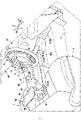
FIG. 1 is an external view of the inside of a vehicle cabin in which an operation bar and an elbow rest member included in a brake manual operation apparatus of the present embodiment are installed, as viewed from the driver seat side. -
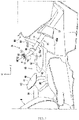
FIG. 2 is a plan view of the inside of the vehicle cabin in which the operation bar and the elbow rest member included in the brake manual operation apparatus of the present embodiment are installed. -
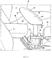
FIG. 3 is a cross-sectional view of a main portion taken along line A-A ofFIG. 2 . -
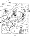
FIG. 4 is an external view of the operation bar included in the brake manual operation apparatus of the present embodiment, as viewed from the driver seat side. -
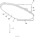
FIG. 5 is an external view illustrating a situation in which the elbow rest member included in the brake manual operation apparatus of the present embodiment is mounted on a vehicle body, as viewed from the driver seat side. -
FIG. 6 is a plan view of the elbow rest member included in the brake manual operation apparatus of the present embodiment. -
FIG. 7 is a front view of the elbow rest member included in the brake manual operation apparatus of the present embodiment. -
FIG. 8 is an explanatory view of functions of the elbow rest member which illustrates, according to the physique of a driver, a situation in which the driver performs a brake operation using the operation bar in a state of his or her elbow hitting against the elbow rest member. - Hereinafter, an embodiment of the present invention will be described in detail based on the drawings.
- In the figures, arrow F indicates the vehicle front side; arrow U, the vehicle upper side; arrow R, the vehicle right side; arrow L, the vehicle left side; arrow X, the axis direction of a steering wheel; arrow Xu, the upper side of the axis direction of the steering wheel (driver side); arrow Xd, the lower side of the axis direction of the steering wheel (the opposite side of the driver side).
- As illustrated in
FIGS. 1 to 4 , a vehicle of the present embodiment is a right-hand drive vehicle and includes a brakemanual operation apparatus 10 that allows a driver with a lower limb disability who has difficulty in a depression operation of a brake pedal or an accelerator pedal with his or her foot to manually perform a brake operation in a state of being seated on adriver seat 8, and an accelerator manual operation apparatus 30 (seeFIGS. 2 and4 ) that allows the driver to manually perform an acceleration operation in a state of being seated on thedriver seat 8. - Note that the brake
manual operation apparatus 10 of the present embodiment corresponds to a driving assistance apparatus of the present invention. - The brake
manual operation apparatus 10 and the acceleratormanual operation apparatus 30 are incorporated into a base vehicle by modifying the base vehicle. The brakemanual operation apparatus 10 and the acceleratormanual operation apparatus 30 will be described hereinafter, but prior to that, a description will be given of a schematic structure of the base vehicle. - The
driver seat 8 and apassenger seat 3 are mounted on the respective right and left sides of a front portion of a floor panel 2 (seeFIG. 3 ) of a vehicle cabin in the vehicle, and as illustrated inFIGS. 2 and4 , asteering wheel 6 that is operated in a state of being gripped by a driver seated on thedriver seat 8 is provided in front of thedriver seat 8. - Furthermore, although illustration is omitted, the
steering wheel 6 includes a paddle shift switch formed by a pair of a shift-up switch for upshift and a shift-down switch for downshift. - In this example, the shift-up switch is included on a rear face of a right-
side spoke portion 6a, and the shift-down switch is included on a rear face of a left-side spoke portion 6b (illustration omitted). - As illustrated in
FIGS. 1 to 4 , aninstrument panel 80 is provided in a front end of the vehicle cabin over the whole vehicle width direction of the vehicle cabin. Acenter console 85 extending in the front-rear direction is provided between thedriver seat 8 and thepassenger seat 3 in the front portion of thefloor panel 2 of the vehicle cabin. Theinstrument panel 80 and thecenter console 85 both form a part of an interior member of the vehicle cabin, and a front portion of thecenter console 85 is integrally connected to a vehicle-width-direction center portion of theinstrument panel 80. - As illustrated in
FIGS. 1 to 3 , on an upper face of thecenter console 85 extending in the front-rear direction, various operation portions such as ashift knob 86 for a gear-shifting operation and astart switch 87,cup holders FIG. 2 ), and an armrest 90 are provided in this order from the front side to the rear side. - Note that, as illustrated in
FIG. 2 , each of thecup holders lid 89 that opens and closes an opening thereof. In this example, thecup holder 88b for an occupant seated on thepassenger seat 3 and thecup holder 88a for the driver are disposed in parallel on the respective left and right sides in an intermediate region between the various operation portions and the armrest 90 in the front-rear direction on the upper face of thecenter console 85. Note thatFIG. 2 illustrates only thelid 89 included in thecup holder 88b for the occupant. - The intermediate region on the upper face of the
center console 85 is not limited to being formed in a recess shape as thecup holders - As illustrated in
FIGS. 1 ,2 , and4 , adisplay portion 81 of various measurement instruments such as a tachometer and a speed meter is disposed in front of thedriver seat 8 in theinstrument panel 80 so as to be visible through thesteering wheel 6, anair conditioning outlet 82 is disposed above a connection portion of the left side of thedisplay portion 81 and the front portion of thecenter console 85, and adisplay 84 of a navigation device is provided below theair conditioning outlet 82. - Note that an accelerator pedal (illustration omitted) is provided at a position at which a right foot of the driver seated on the
driver seat 8 is placed, on thefloor panel 2 in front of thedriver seat 8 in the vehicle cabin, and a brake pedal (illustration omitted) is provided near the left side from the accelerator pedal (vehicle-width-direction center side). - The accelerator pedal is an organ-type pedal that operates a throttle valve of an engine, and the brake pedal is a suspended-type pedal that operates a brake, both of which are typical pedals included in the base vehicle.
- Hereinafter, the brake
manual operation apparatus 10 will be described. - As illustrated in
FIGS. 1 to 4 , the brakemanual operation apparatus 10 is installed on the left side with respect to thesteering wheel 6 in the vicinity of the front side of thedriver seat 8, that is, in the vicinity of aright wall 85a (seeFIG. 3 ) of a connection portion of thecenter console 85 and theinstrument panel 80. - As illustrated in
FIGS. 1 ,3 , and4 , an upper portion of the brakemanual operation apparatus 10 includes abrake operation unit 11, and a lower portion of the brakemanual operation apparatus 10 includes an operationamount transmission unit 12. Furthermore, as illustrated inFIGS. 1 to 4 , thebrake operation unit 11 includes anoperation bar 13 and anaxially supporting portion 14. - The
operation bar 13 is made of a metal pipe material (a so-called round pipe) having a circular orthogonal cross-section in the axis direction and is disposed in a posture inclined in a front-low rear-high shape. Specifically, an upper portion of theoperation bar 13 is located at a height at which the driver seated on thedriver seat 8 can operate theoperation bar 13 with his or her left hand, at a position in the vicinity of the left side with respect to the steering wheel 6 (seeFIG. 2 ) . Furthermore, as illustrated inFIGS. 1 and3 , theoperation bar 13 extends in the front-lower direction toward thefloor panel 2 in the vicinity of the front side of thedriver seat 8. - A lower portion of the
operation bar 13 is axially supported by theaxially supporting portion 14 such that theoperation bar 13 is slidably displaced in the front-lower direction with respect to theaxially supporting portion 14 by being subjected to a pushing operation (that is, a brake operation) in the front-lower direction along the axis direction of theoperation bar 13. - The
operation bar 13 slides in the axis direction between a neutral position and a maximum pushing position at which theoperation bar 13 is further pushed from the neutral position by a predetermined length in the front-lower direction. Note that theoperation bar 13 illustrated inFIGS. 1 to 4 illustrates a state of being disposed in the neutral position. - The operation
amount transmission unit 12 intervenes between thebrake operation unit 11 and the brake pedal (illustration omitted) and is configured to transmit to the brake pedal an operation force (operation amount) of the sliding displacement of theoperation bar 13 in the front-lower direction. That is, the brake pedal included in the base vehicle is configured to operate in conjunction with sliding movement of theoperation bar 13 in the axis direction due to the manual brake operation. - Thus, the brake
manual operation apparatus 10 can activate the brake by rotating the brake pedal at a depression amount according to a sliding amount (pushing amount) of theoperation bar 13 in the front-lower direction during the manual brake operation using theoperation bar 13. - Furthermore, similarly to the brake pedal, the
operation bar 13 is biased to the neutral position, and the neutral positions of theoperation bar 13 and the brake pedal are associated with each other. Thus, when pushing of theoperation bar 13 from the neutral position in the front-lower direction is released by the driver, theoperation bar 13 and the brake pedal are simultaneously restored to the respective neutral positions. - The
operation bar 13 included in the brakemanual operation apparatus 10 of the present embodiment is formed by integrating anoperation bar body 15 and agrip portion 16 provided at an upper end of theoperation bar body 15. - The
operation bar body 15 is integrally formed having abase portion 15a and aninclined portion 15c linearly extending so as to be inclined to the vehicle-width-direction outer side as it goes upward, via abent portion 15b from an upper end of thebase portion 15a. - The
base portion 15a extends in a direction coinciding with the front-rear direction in a vehicle plan view, linearly extends in a posture inclined in a front-low rear-high shape coaxially with theaxially supporting portion 14, and is formed with the same diameter along the axis direction. A lower portion of thebase portion 15a is axially supported in a state of being fitted in theaxially supporting portion 14 through an opening open toward the rear upper side of theaxially supporting portion 14 in a tubular shape. - The
inclined portion 15c is inclined in a front-low rear-high shape similarly to thebase portion 15a, while theinclined portion 15c is inclined in the front-low rear-high shape in a steeper posture (rising posture) than thebase portion 15a and, as described above, extends so as to be inclined to the vehicle-width-direction outer side as it goes upward. - Thus, the
inclined portion 15c supports thegrip portion 16 from therebelow in a manual operation region (a position corresponding to a boundary portion between thecenter console 85 and thefloor panel 2 in a plan view) (seeFIG. 2 ). Note that theinclined portion 15c has a lower end formed with the substantially same diameter as thebase portion 15a, and is formed in a tapered shape as it goes upward. - As illustrated in
FIGS. 1 ,3 , and4 , a plurality of operation buttons for the driver to perform various operations while gripping thegrip portion 16 are disposed on thegrip portion 16. - Specifically, a
brake lock switch 17 and ahazard switch 18 are disposed on a right-side face 16a of thegrip portion 16. - The
brake lock switch 17 can lock and hold a brake state when the brake is in an activated state. That is, thebrake lock switch 17 is pressed in a state in which theoperation bar 13 for the brake operation is pushed down, and thereby can hold theoperation bar 13 in the pushed down state. Thebrake lock switch 17 is pressed again and thereby can release the brake state. - In the present embodiment, similarly to a hazard switch (illustration omitted) provided in front of the
driver seat 8 in theinstrument panel 80, thehazard switch 18 can blink a hazard lamp (emergency blinking lamp) by being pressed by the driver and thereby can alert people around the vehicle and notify them of danger. - Note that the
hazard switch 18 is configured to stop the blinking of the hazard lamp by being pressed again. - Furthermore, as illustrated in
FIG. 3 , apaddle shift switch 23 is provided on a front lower face 16d of the grip portion 16 (a back face on the non-driver side). Note that, although illustration is omitted, thepaddle shift switch 23 is a seesaw-type switch in which a shift-down switch for shift-down and a shift-up switch for shift-up are disposed side by side in a pair. - Furthermore, as illustrated in
FIGS. 1 ,2 , and4 , the acceleratormanual operation apparatus 30 of the present embodiment includes anaccelerator lever 31 as an acceleration operation member disposed in the vicinity of the radially inner side with respect to arim portion 61 of thesteering wheel 6. - The
accelerator lever 31 is configured to be capable of being pushed downward in the steering axis direction (non-driver side) from a neutral position by the driver using, for example, a thumb of his or her hand gripping thesteering wheel 6. Furthermore, theaccelerator lever 31 is biased to the neutral position (upward) so as to be capable of being restored to the neutral position from a position at which theaccelerator lever 31 is pushed from the neutral position. - Thus, the driver can perform a pushing operation of the
accelerator lever 31 between the neutral position and a maximum pushing position at which theaccelerator lever 31 is pushed by a predetermined length, and according to the pushing amount, the driver can perform an opening operation of the throttle valve of the engine, that is, an acceleration and deceleration operation of the vehicle. - As illustrated in
FIGS. 1 to 3 , in the vehicle of the present embodiment, on the vehicle rear side of thegrip portion 16 in the vehicle cabin and at a position corresponding to an elbow portion of a left arm of the driver in a state in which the driver grips thegrip portion 16 so as to be capable of operating theoperation bar 13, anelbow rest member 40 that allows abutment of the elbow portion is provided. - The
elbow rest member 40 is provided in a protruding manner at a position corresponding to thecup holder 88a for the driver in the center console 85 (that is, a position near the driver side in the vehicle width direction of the center console 85). - As illustrated in
FIGS. 1 and3 , theelbow rest member 40 is formed having an elbowrest member body 41, asupport frame 42, and a vehiclebody mounting portion 43. - As illustrated in
FIGS. 5 and7 , the vehiclebody mounting portion 43 includes a core material (illustration omitted) integrally formed with thesupport frame 42, anexterior member 44 externally provided on the core material, and atrim panel 45 installed on an upper face of theexterior member 44. - The core material, although illustration is omitted, is formed of a metal frame forming a framework of the vehicle
body mounting portion 43, or the like. In the present embodiment, thesupport frame 42 described later is extended downward to a section corresponding to the vehiclebody mounting portion 43, and this downward extended portion is the core material for the vehicle body mounting portion 43 (illustration omitted). - The
exterior member 44 is formed of an elastic member such as urethane and is attached to mainly an outer periphery of the core material. Thus, the diameter of the vehiclebody mounting portion 43 is formed slightly larger than the inner diameter of thecup holder 88a in a recess shape. However, the length of the vehiclebody mounting portion 43 in the up-down direction is formed shorter than the depth of thecup holder 88a. The trim panel 45 (dummy lid) is formed in a plate shape having a size corresponding to the lid (illustration omitted) included in thecup holder 88a for the driver. - In mounting the
elbow rest member 40 on a vehicle body, the lid of thecup holder 88a for the driver is removed to bring thecup holder 88a into an open state, and as indicated by a white arrow inFIG. 5 , the vehiclebody mounting portion 43 is fitted in therecess cup holder 88a through the opening, so that the vehiclebody mounting portion 43 is fitted and held in thecup holder 88a. Note that, in the state in which the vehiclebody mounting portion 43 is fitted and held in thecup holder 88a, thetrim panel 45 is in a state of being installed at a position corresponding to the lid of thecup holder 88a for the driver before theelbow rest member 40 is mounted on the vehicle body. - Furthermore, the
elbow rest member 40 can be removed from the vehicle body by withdrawing the vehiclebody mounting portion 43 from thecup holder 88a, and thecup holder 88a is restored to a recess form such that a drink container can be placed thereon. - In the state in which the vehicle
body mounting portion 43 is mounted on thecup holder 88a for the driver, as illustrated inFIGS. 1 and3 , thesupport frame 42 is provided in a protruding manner from a position corresponding to thecup holder 88a for the driver. - As illustrated in
FIG. 7 , thewhole support frame 42 except for an upper portion thereof extends in the up-down direction (vertical direction), and as illustrated inFIGS. 1 ,3 , and5 , the upper portion of thesupport frame 42 is provided inclined so as to be located rearward as it goes upward. Thesupport frame 42 has an upper end portion mounted on a lower portion of the elbowrest member body 41 and supports the elbowrest member body 41 from immediately thereunder (seeFIG. 7 ). - The elbow
rest member body 41 is formed in a plate shape including a frame (illustration omitted), a cushion pad, and atrim cover 47 covering the frame and the cushion pad (illustration omitted), and one face (right face) of the elbowrest member body 41 is disposed so as to substantially face the driver (driver seat 8) in the vehicle width direction. - The frame is made of a metal material or a relatively hard resin material and forms a framework of the elbow
rest member body 41. The cushion pad is made of, for example, a foamed material such as a flexible urethane foam and is assembled to the frame while covering at least a right face of the frame (a face on the side substantially facing the driver). - The
trim cover 47 is made of, for example, a skin material such as leather (natural leather, synthetic leather) or fabric (knit, woven fabric, non-woven fabric), has a right face skin disposed on the right face of the elbowrest member body 41, a left face skin disposed on a left face of the elbowrest member body 41, and a gusset skin connecting the right face skin and the left face skin, and is formed by suturing these skins. - The right face of the elbow
rest member body 41 in the vehicle width direction is formed as anelbow rest face 48. Theelbow rest face 48 secures flexibility by the cushion pad covering the right face of the frame, so as not to hurt the driver when abutting on his or her elbow. - As illustrated in
FIGS. 2 ,6 , and7 , the elbowrest member body 41 is supported by thesupport frame 42 in a posture in which theelbow rest face 48 is inclined so as to be located on the driver (driver seat 8) side in the vehicle width direction as it goes downward. - In this example, the
elbow rest face 48 is inclined at an inclination angle of about 35 degrees with respect to the vertical direction in a vehicle front view such that the upper side thereof is located on thepassenger seat 3 side and the lower side thereof is located on thedriver seat 8 side. However, the inclination angle of the elbow rest face 48 can be set to any angle at which an elbow portion of a left arm of the driver easily abuts on the elbow rest face 48 in a state in which the driver grips thegrip portion 16. - As illustrated in
FIG. 2 , the elbowrest member body 41 is disposed at a position in the vicinity of the left side of a seat portion of thedriver seat 8 in a plan view, and the lower portion of the elbowrest member body 41 is disposed so as to overlap with at least a part of thegrip portion 16 in the vehicle width direction. In this example, the elbowrest member body 41 is disposed at a position on the slightly left side with respect to thegrip portion 16. Thearmrest 90 is installed on the rear side of the elbowrest member body 41, and as illustrated inFIG. 3 , the whole elbowrest member body 41 except for the lower portion thereof in the up-down direction is formed higher so as to project upward from an upper face of thearmrest 90. Only an upper portion of the elbowrest member body 41 is disposed at the substantially same (overlapping in the up-down direction) height as the grip portion 16 (seeFIG. 3 ). - Furthermore, as illustrated in
FIGS. 1 and3 , the elbowrest member body 41 is inclined so as to be located on the vehicle rear side as it goes upward, and is formed in a substantially parallelogram shape in which each of corner portions thereof is formed in a chamfered shape in a vehicle side view. - Specifically, as illustrated in
FIGS. 5 and7 , alower side 41d of the elbowrest member body 41 is linearly formed substantially horizontally in the vehicle front-rear direction, and as illustrated inFIGS. 5 and6 , arear side 41r and afront side 41f are both inclined so as to be located on the vehicle rear side as they go upward, and linearly extend in parallel to each other. - As illustrated in
FIGS. 1 to 4 , the brake manual operation apparatus 10 (driving assistance apparatus) of the above-described embodiment includes, in the vehicle cabin, the operation bar 13 (brake operation portion) that allows the manual brake operation, and is characterized in that theoperation bar 13 includes thegrip portion 16, and as illustrated inFIGS. 1 to 3 , theelbow rest member 40 is provided at, in the vehicle rear side of thegrip portion 16, a position on which the elbow portion of the driver can abut in a state in which the driver grips thegrip portion 16 so as to be capable of operating theoperation bar 13. - According to the configuration, the brake operation is performed by placing the self-weight of an upper arm of the driver on the elbow
rest member body 41 in theelbow rest member 40 and adjusting the angle of his or her forearm using the elbow supported by the elbowrest member body 41 as a pivot, so that it is not necessary to move the whole left arm, and accordingly it is possible to delicately control the braking force with the forearm. - Accordingly, even a physically disabled driver can easily manually operate a delicate brake operation with his or her hand in the same manner as with his or her foot which is performed using a foot brake.
- Furthermore, according to the configuration, during the brake operation using the
operation bar 13, even a physically disabled driver does not need to lose his or her posture and can maintain a comfortable driving posture, and thus, for example, the driver also can easily manually perform a steering operation, an acceleration operation, a shift change operation, and the like and consequently can freely perform a driving operation. - Specifically, a description will be given of a procedure and a method for a large driver Dm in
FIG. 8 to perform the brake operation using theoperation bar 13 in a state of his or her elbow hitting against the elbowrest member body 41. First, during the brake operation, the driver Dm pushes theoperation bar 13 in the front-lower direction using the elbow of his or her left arm hitting against the elbow rest face 48 of the elbowrest member body 41 as a starting point. Thus, an armpit opening is suppressed in any sides in a front view and side view of the driver Dm, and the driver Dm can push his or her forearm while maintaining a comfortable driving posture without losing the driving posture. - Furthermore, when the driver Dm pushes the forearm in the front-lower direction by pushing the
operation bar 13 with his or her left hand, it is preferable that, while the elbow of the left arm is guided along the elbow rest face 48 while maintaining a state of abutting on the elbowrest member body 41, the forearm is pushed in the front-lower direction. Thus, the operation track of the left hand in the front-lower direction during the brake operation can be assisted by the elbowrest member body 41, and consequently unnecessary movement such as a wobble of the left hand of the driver Dm is suppressed, enabling operations and control of theoperation bar 13 with a lesser loss. - As an aspect of the present invention, as illustrated in
FIGS. 1 to 3 ,6 , and7 , it is characterized in that the elbow rest face 48 of the elbowrest member body 41 is provided toward the driver side in the vehicle width direction, and theelbow rest face 48 is provided inclined so as to be located on the driver side as it goes downward. - According to the configuration, regardless of the physique of the driver, it is possible to cause the elbow portion of the driver to firmly abut on the elbow rest face 48 while the driver holds a driving posture appropriate for the brake operation. Thus, it is possible to easily perform a strong brake operation.
- Furthermore, it is possible to cause the elbow portion of the driver to firmly abut on the elbow rest face 48 without adjustment of, in the
elbow rest face 48, a height of a point against which the elbow of the driver appropriately hits, according to the physique of the driver. - Specifically, as described above, the elbow rest face 48 of the elbow
rest member body 41 is provided inclined so as to be located on (approach) the driver side as it goes downward, and thus, as indicated by a solid line inFIG. 8 , in the case where the physique of the driver Dm is relatively large, an elbow portion of the driver Dm abuts on a relatively upward (rear upper) position in the elbow rest face 48 inclined to the driver Dm side as it goes downward (see an elbow rest point Pm inFIG. 8 ). - On the other hand, as indicated by a virtual line in
FIG. 8 , in the case where the physique of a driver Dw is relatively small, an elbow portion of the driver Dw abuts on a relatively downward (front lower) position in the elbow rest face 48 inclined to the driver Dw side as it goes downward (see an elbow rest point Pw inFIG. 8 ). - As described above, the elbow rest face 48 of the elbow
rest member body 41 is provided inclined so as to be located on the driver side as it goes downward, and thus, regardless of the physique of the driver, it is possible to cause the elbow portion of the driver to firmly abut (be supported) at the elbow rest point Pm or Pw in the elbow rest face 48 which is appropriate for the driver to perform the brake operation. - Accordingly, the driver, regardless of the physique, can easily perform a strong brake operation while holding the driving posture, that is, while holding a posture of performing a normal brake operation in a state of gripping the
grip portion 16 by stretching the left arm forward. - Furthermore, the driver can cause the elbow to abut on an appropriate elbow rest point without adjustment of a position of the elbow rest point (a height and vehicle-width-direction position of a point against which the elbow hits) in the elbow rest face 48 according to the physique of the driver and can utilize the elbow
rest member body 41 without inconvenience of the adjustment of the elbow rest point. - Furthermore, the elbow rest face 48 of the elbow
rest member body 41 is not a horizontal face as in, in thearmrest 90, the upper face on which the arm of the driver is placed, but is provided so as to face the driver side in the vehicle width direction, and thus it is possible to cause the elbow portion of the left arm of the driver to firmly hit against theelbow rest face 48 when the driver pushes theoperation bar 13 in the front-lower direction in a state of gripping thegrip portion 16 during the brake operation with the left hand. Thus, it is possible to firmly suppress escape of the elbow portion of the left arm of the driver to thepassenger seat 3 side from the position of the elbow rest face 48 in the vehicle width direction. That is, it is possible to suppress opening of the armpit angle of the left arm of the driver in a vehicle front view and control a delicate brake with the forearm. - As an aspect of the present invention, as illustrated in
FIG. 3 , it is characterized in that at least a part of the elbow rest face 48 of the elbow rest member body 41 (a substantial elbow rest portion in the elbow rest face 48) is provided above the armrest 90 provided in thecenter console 85 of the vehicle. - Specifically, in the elbow
rest member body 41, an upward portion of the elbow rest face 48 at least from an intermediate position thereof in the up-down direction is provided above the upper face of thearmrest 90. Furthermore, as illustrated inFIG. 2 , the elbowrest member body 41 is provided at a position on the vehicle front side from thearmrest 90 and a position near the driver side in the vehicle width direction. - According to the configuration, when the driver places the elbow on the elbow
rest member body 41, the driver can perform the brake operation while holding an appropriate driving posture without leaning against thecenter console 85 side as in the case of placing the forearm on thearmrest 90. - As an aspect of the present invention, as illustrated in
FIGS. 1 ,2 , and5 , it is characterized in that theelbow rest member 40 is formed so as to be capable of being mounted on thecup holder 88a for the driver provided in thecenter console 85. - According to the configuration, it is possible to easily attach and detach the
elbow rest member 40 only by inserting and extracting theelbow rest member 40 into and from therecess cup holder 88a. Thus, for example, in the case where the driver is a healthy person who does not require the manual brake operation, it is possible for the driver to remove theelbow rest member 40 from the vehicle body, and thus it becomes easier to utilize thearmrest 90. Furthermore, there is no need for adding a large-scale alteration to the base vehicle in mounting theelbow rest member 40 on the vehicle body. - Furthermore, as an aspect of the present invention, as illustrated in
FIGS. 1 to 3 ,5 , and6 , the elbowrest member body 41 in theelbow rest member 40 is provided so as to be located on the vehicle rear side as it goes upward. - The elbow
rest member body 41 is provided so as to be located on the vehicle rear side as it goes upward, and thus the driver can cause the elbow to reliably abut on the elbow rest face 48 regardless of a difference of the elbow rest point in the front-rear direction and the up-down direction due to a difference of the physique of the driver. - Furthermore, since the elbow
rest member body 41 is provided so as to be located on the vehicle rear side as it goes upward, the driver can continue to guide the elbow portion along the track of the elbow portion in the front-lower direction when pushing theoperation bar 13 in the front-lower direction from a state of the elbow hitting against the elbow rest point. - For example, as indicated by the solid line in
FIG. 8 , in the case where the physique of the driver Dm is relatively large, the elbow portion of the driver Dm abuts on a relatively rearward (rear upper) position in the elbow rest face 48 (see the elbow rest point Pm inFIG. 8 ). Furthermore, as indicated by the virtual line inFIG. 8 , in the case where the physique of the driver Dw is relatively small, the elbow portion of the driver Dw abuts on a relatively forward (front lower) position in the elbow rest face 48 (see the elbow rest point Pw inFIG. 8 ). - Furthermore, the elbow
rest member body 41 is not unintentionally formed large and is provided in a minimum necessary size so as to be located on the vehicle rear side as it goes upward, and thus the driver is not hindered by theelbow rest member 40 provided in thecenter console 85 in accessing various switches provided in thecenter console 85, theshift knob 86 for the gear-shifting operation, or thestart switch 87. Furthermore, it is possible to reduce a cooped-up feeling due to separation between thepassenger seat 3 and thedriver seat 8 by theelbow rest member 40 provided in a protruding manner between thepassenger seat 3 and thedriver seat 8. - Furthermore, as an aspect of the present invention, as illustrated in
FIGS. 2 to 4 , thegrip portion 16 is included in an upper end of theoperation bar 13, and the elbowrest member body 41 is provided at a position on the vehicle rear side and the vehicle left side from the position of thegrip portion 16 included in the upper end of theoperation bar 13, in the vehicle width direction (the non-driver side in the vehicle width direction). Furthermore, theinclined portion 15c inclined to the left side as it goes toward the vehicle upper side (the side approaching the elbowrest member body 41 in the vehicle width direction) is provided at an upper portion of the operation bar body 15 (brake operation body). - According to the configuration, in a vehicle plan view, the
inclined portion 15c provided at the upper portion of theoperation bar body 15 can coincide with an orientation of the forearm of the left arm in a plan view which extends toward the vehicle front side and the vehicle-width-direction inner side from the elbow portion of the left arm abutting on the elbowrest member body 41 to the left hand. - The
inclined portion 15c as described above is included in the upper portion of theoperation bar 13, so that, when the driver brings the elbow portion of the left arm into firmly abutting on theelbow rest face 48 and pushes the grip portion 16 (operation bar 13) in the front-lower direction with the left hand, a force of pushing the grip portion 16 (in particular, a force toward the inner direction in the vehicle width direction) can be firmly received by theinclined portion 15c. - Accordingly, the driver can effectively transfer to the
operation bar body 15 the force of pushing thegrip portion 16 using the elbow rest face 48 as a pivot of the elbow, consequently enabling a smooth pushing operation of theoperation bar 13. - The present invention is not limited to only the configurations of the above-described embodiment and can be formed in various embodiments.
-
- 10
- brake manual operation apparatus (driving assistance apparatus)
- 13
- operation bar (brake operation portion)
- 16
- grip portion
- 40
- elbow rest member
- 48
- elbow rest face of elbow rest member
- 85
- center console
- 88a
- cup holder for driver (cup holder)
- 90
- armrest
Claims (15)
- A driving assistance apparatus comprising (10), in a vehicle cabin, a brake operation portion that allows a manual brake operation, the brake operation portion comprising a grip portion (16), the driving assistance apparatus (10) being characterized in that
an elbow rest member (40) is provided at, in a vehicle rear side of the grip portion (16), a position on which an elbow portion of a driver can abut in a state in which the driver grips the grip portion (16) so as to be capable of operating the grip portion (16). - The driving assistance apparatus (10) according to claim 1, characterized in that an elbow rest face (48) of the elbow rest member (40) is provided toward a driver side in a vehicle width direction, and the elbow rest face (48) is provided inclined so as to be located on the driver side as the elbow rest face (48) goes downward.
- The driving assistance apparatus (10) according to claim 1 or 2, wherein an elbow rest member body (41) of the elbow rest member (40) is inclined so as to be located on a vehicle rear side as it goes upward.
- The driving assistance apparatus (10) according to any preceding claims, wherein at least a part of an elbow rest face (48) of the elbow rest member (40) is provided above an armrest (90) provided in a center console (85) of a vehicle.
- The driving assistance apparatus (10) according to claim 4, wherein at least a part of the elbow rest face (48) is provided at a position on the vehicle front side from the armrest (90).
- The driving assistance apparatus (10) according to any preceding claims , wherein the elbow rest member (40) is formed so as to be capable of being mounted on a cup holder (88a) provided in a center console (85) of a vehicle.
- The driving assistance apparatus (10) according to any preceding claims, wherein the elbow rest member (40) comprises an elbow rest member body (41), wherein a lower portion of the elbow rest member body (41) is disposed so as to overlap with at least a part of the grip portion (16) in a vehicle width direction and/or wherein a face of the elbow rest member body (41) in a vehicle width direction is formed as an elbow rest face (48).
- The driving assistance apparatus (10) according to any preceding claims, wherein the elbow rest member (40) comprises an elbow rest member body (41), a vehicle body mounting portion (43) and a support frame (42) arranged between the elbow rest member body (41) and the vehicle body mounting portion (43), the vehicle body mounting portion (43) preferably having an outer diameter being formed larger than an inner diameter of a cup holder (88a) provided in a center console (85) of a vehicle.
- The driving assistance apparatus (10) according to claim 8, wherein the vehicle body mounting portion (43) includes a core material, preferably a metal, integrally formed with the support frame (42), wherein preferably an exterior member (44) is externally provided on the core material and/or wherein the exterior member (44) is formed of an elastic member and is attached to an outer periphery of the core material, wherein the exterior member (44) preferably forms the outer diameter of the vehicle body mounting portion (43).
- The driving assistance apparatus (10) according to any preceding claims, wherein the elbow rest member body (41) is formed in a parallelogram shape, in which preferably each of corner portions thereof is formed in a chamfered shape, in a vehicle side view.
- The driving assistance apparatus (10) according to any preceding claims, wherein an upper portion of the driving assistance apparatus (10) includes a brake operation unit (11), and a lower portion of the driving assistance apparatus (10) includes an operation amount transmission unit (12), the driving assistance apparatus (10) being configured such that the operation amount transmission unit (12) intervenes between the brake operation unit (11) and a brake pedal of a vehicle and is configured to transmit to the brake pedal an operation force of a sliding displacement of the grip portion (16) preferably in a front-lower direction of the vehicle.
- The driving assistance apparatus (10) according claim 11, wherein the grip portion (16) is biased to a neutral position and/or the neutral position of the grip portion (16) and a neutral position of the brake pedal are associated with each other.
- The driving assistance apparatus (10) according to any preceding claims, further comprising an accelerator manual operation apparatus (30) including an accelerator lever (31) being disposed in a vicinity of a radially inner side with respect to a rim portion (61) of a steering wheel (6) .
- A vehicle comprising the driving assistance apparatus (10) according to any preceding claims.
- The vehicle according to claim 14 comprising a brake pedal being configured to operate in conjunction with a sliding movement of the grip portion (16) preferably in an axis direction of the steering wheel (2).
Applications Claiming Priority (1)
| Application Number | Priority Date | Filing Date | Title |
|---|---|---|---|
| JP2021003547A JP7673409B2 (en) | 2021-01-13 | 2021-01-13 | Driving aids |
Publications (1)
| Publication Number | Publication Date |
|---|---|
| EP4030260A1 true EP4030260A1 (en) | 2022-07-20 |
Family
ID=78957371
Family Applications (1)
| Application Number | Title | Priority Date | Filing Date |
|---|---|---|---|
| EP21215415.7A Pending EP4030260A1 (en) | 2021-01-13 | 2021-12-17 | Driving assistance apparatus |
Country Status (3)
| Country | Link |
|---|---|
| US (1) | US11554701B2 (en) |
| EP (1) | EP4030260A1 (en) |
| JP (1) | JP7673409B2 (en) |
Families Citing this family (3)
| Publication number | Priority date | Publication date | Assignee | Title |
|---|---|---|---|---|
| JP7447398B2 (en) * | 2019-06-18 | 2024-03-12 | マツダ株式会社 | Driving aid device |
| US11643056B2 (en) * | 2021-01-13 | 2023-05-09 | Mazda Motor Corporation | Driving assistance apparatus |
| WO2026074783A1 (en) * | 2024-10-02 | 2026-04-09 | Astemo株式会社 | Steering input device and steer-by-wire-type steering device |
Citations (3)
| Publication number | Priority date | Publication date | Assignee | Title |
|---|---|---|---|---|
| JP2002120590A (en) | 2000-10-13 | 2002-04-23 | Honda Motor Co Ltd | Vehicles for the physically handicapped |
| JP2006028953A (en) * | 2004-07-20 | 2006-02-02 | Shin Caterpillar Mitsubishi Ltd | Manual operating device of working machine |
| JP4680845B2 (en) * | 2006-07-06 | 2011-05-11 | 株式会社東海理化電機製作所 | Vehicle driving device |
Family Cites Families (11)
| Publication number | Priority date | Publication date | Assignee | Title |
|---|---|---|---|---|
| FR2407093A1 (en) * | 1977-10-28 | 1979-05-25 | Segal Patrick | Automatic transmission car for handicapped person - has hand control of pedals by two push rods fixed to pedals via ball joints |
| US4997054A (en) * | 1989-04-14 | 1991-03-05 | J. I. Case Company | Adjustable wrist rest |
| GB2281955A (en) * | 1993-09-21 | 1995-03-22 | Christopher John Ryley | Portable hand controls for operating vehicle pedals. |
| DE19607398C1 (en) * | 1996-02-28 | 1998-01-29 | Jungheinrich Ag | Manually operated positioning device for vehicle seat |
| JP3352041B2 (en) | 1998-11-11 | 2002-12-03 | 株式会社小松製作所 | Mono-lever steering system for work vehicles |
| DE10115964B4 (en) | 2001-03-27 | 2013-05-23 | Volkswagen Ag | Rear seat of a vehicle |
| JP2002373027A (en) | 2001-06-15 | 2002-12-26 | Toyota Motor Corp | Operating device and vehicle operating system |
| SE525171C2 (en) * | 2003-05-28 | 2004-12-14 | Volvo Constr Equip Holding Se | Armrest for use with a vehicle seat |
| JP5381092B2 (en) | 2008-12-26 | 2014-01-08 | マツダ株式会社 | Vehicle seat device |
| US9403455B2 (en) | 2014-09-19 | 2016-08-02 | Ford Global Technologies, Llc | Adjustable armrest device for securing in a cup holder of a vehicle |
| JP6150264B1 (en) * | 2016-09-08 | 2017-06-21 | 株式会社パペラトレーダス | Driving assistance device for automobile and its mounting method |
-
2021
- 2021-01-13 JP JP2021003547A patent/JP7673409B2/en active Active
- 2021-12-17 EP EP21215415.7A patent/EP4030260A1/en active Pending
- 2021-12-20 US US17/555,572 patent/US11554701B2/en active Active
Patent Citations (3)
| Publication number | Priority date | Publication date | Assignee | Title |
|---|---|---|---|---|
| JP2002120590A (en) | 2000-10-13 | 2002-04-23 | Honda Motor Co Ltd | Vehicles for the physically handicapped |
| JP2006028953A (en) * | 2004-07-20 | 2006-02-02 | Shin Caterpillar Mitsubishi Ltd | Manual operating device of working machine |
| JP4680845B2 (en) * | 2006-07-06 | 2011-05-11 | 株式会社東海理化電機製作所 | Vehicle driving device |
Also Published As
| Publication number | Publication date |
|---|---|
| US20220219654A1 (en) | 2022-07-14 |
| US11554701B2 (en) | 2023-01-17 |
| JP7673409B2 (en) | 2025-05-09 |
| JP2022108511A (en) | 2022-07-26 |
Similar Documents
| Publication | Publication Date | Title |
|---|---|---|
| US11554701B2 (en) | Driving assistance apparatus | |
| US11897537B2 (en) | Driver assistance system | |
| US11643056B2 (en) | Driving assistance apparatus | |
| JP4813738B2 (en) | Steering device for wire-driven vehicle | |
| US11938814B2 (en) | Driving assistance device | |
| US20160264022A1 (en) | Seat device of vehicle | |
| US11755054B2 (en) | Driver assistance system | |
| JPH1097333A (en) | Operation element device for controlling longitudinal motion and lateral motion of automobile | |
| EP1400426B1 (en) | Drive controller for a rail vehicle | |
| JP2015189371A (en) | vehicle | |
| KR200474609Y1 (en) | Assistive devices for disabled motoring | |
| JP2002258959A (en) | Vehicle driving device | |
| JPH1085260A (en) | Transport device for carrying wheelchair | |
| JP2934013B2 (en) | Operating device for automatic transmission for vehicles | |
| JP4223821B2 (en) | Vehicle occupant protection device | |
| JP3209339B2 (en) | Operating device for automatic transmission for vehicles | |
| Trzesniowski | Cockpit | |
| KR20250119415A (en) | Driver foot comfort system, passenger foot entertainment systme and safe use method | |
| KR101551813B1 (en) | Auxiliary Pedal Device | |
| Korendiy et al. | TRANSPORT TECHNOLOGIES Vol. 5, No. 2, 2024 | |
| JPH0840101A (en) | Operation force adjustment device for driving equipment | |
| JPH0976805A (en) | Integral console device for seat | |
| JP2014133463A (en) | Electric vehicle | |
| KR20020090376A (en) | Seat to establish massage-device for getting over sleepy spell of automobile |
Legal Events
| Date | Code | Title | Description |
|---|---|---|---|
| PUAI | Public reference made under article 153(3) epc to a published international application that has entered the european phase |
Free format text: ORIGINAL CODE: 0009012 |
|
| STAA | Information on the status of an ep patent application or granted ep patent |
Free format text: STATUS: THE APPLICATION HAS BEEN PUBLISHED |
|
| AK | Designated contracting states |
Kind code of ref document: A1 Designated state(s): AL AT BE BG CH CY CZ DE DK EE ES FI FR GB GR HR HU IE IS IT LI LT LU LV MC MK MT NL NO PL PT RO RS SE SI SK SM TR |
|
| STAA | Information on the status of an ep patent application or granted ep patent |
Free format text: STATUS: REQUEST FOR EXAMINATION WAS MADE |
|
| 17P | Request for examination filed |
Effective date: 20230120 |
|
| RBV | Designated contracting states (corrected) |
Designated state(s): AL AT BE BG CH CY CZ DE DK EE ES FI FR GB GR HR HU IE IS IT LI LT LU LV MC MK MT NL NO PL PT RO RS SE SI SK SM TR |
|
| STAA | Information on the status of an ep patent application or granted ep patent |
Free format text: STATUS: EXAMINATION IS IN PROGRESS |
|
| 17Q | First examination report despatched |
Effective date: 20240227 |