EP4030135A1 - Induktive sensoreinheit - Google Patents
Induktive sensoreinheit Download PDFInfo
- Publication number
- EP4030135A1 EP4030135A1 EP22000004.6A EP22000004A EP4030135A1 EP 4030135 A1 EP4030135 A1 EP 4030135A1 EP 22000004 A EP22000004 A EP 22000004A EP 4030135 A1 EP4030135 A1 EP 4030135A1
- Authority
- EP
- European Patent Office
- Prior art keywords
- sensor
- unit
- inductance
- coil
- actual value
- Prior art date
- Legal status (The legal status is an assumption and is not a legal conclusion. Google has not performed a legal analysis and makes no representation as to the accuracy of the status listed.)
- Granted
Links
Images

Classifications
-
- G—PHYSICS
- G01—MEASURING; TESTING
- G01D—MEASURING NOT SPECIALLY ADAPTED FOR A SPECIFIC VARIABLE; ARRANGEMENTS FOR MEASURING TWO OR MORE VARIABLES NOT COVERED IN A SINGLE OTHER SUBCLASS; TARIFF METERING APPARATUS; MEASURING OR TESTING NOT OTHERWISE PROVIDED FOR
- G01D3/00—Indicating or recording apparatus with provision for the special purposes referred to in the subgroups
- G01D3/08—Indicating or recording apparatus with provision for the special purposes referred to in the subgroups with provision for safeguarding the apparatus, e.g. against abnormal operation, against breakdown
-
- G—PHYSICS
- G01—MEASURING; TESTING
- G01D—MEASURING NOT SPECIALLY ADAPTED FOR A SPECIFIC VARIABLE; ARRANGEMENTS FOR MEASURING TWO OR MORE VARIABLES NOT COVERED IN A SINGLE OTHER SUBCLASS; TARIFF METERING APPARATUS; MEASURING OR TESTING NOT OTHERWISE PROVIDED FOR
- G01D3/00—Indicating or recording apparatus with provision for the special purposes referred to in the subgroups
- G01D3/028—Indicating or recording apparatus with provision for the special purposes referred to in the subgroups mitigating undesired influences, e.g. temperature, pressure
- G01D3/036—Indicating or recording apparatus with provision for the special purposes referred to in the subgroups mitigating undesired influences, e.g. temperature, pressure on measuring arrangements themselves
- G01D3/0365—Indicating or recording apparatus with provision for the special purposes referred to in the subgroups mitigating undesired influences, e.g. temperature, pressure on measuring arrangements themselves the undesired influence being measured using a separate sensor, which produces an influence related signal
-
- G—PHYSICS
- G01—MEASURING; TESTING
- G01V—GEOPHYSICS; GRAVITATIONAL MEASUREMENTS; DETECTING MASSES OR OBJECTS; TAGS
- G01V3/00—Electric or magnetic prospecting or detecting; Measuring magnetic field characteristics of the earth, e.g. declination, deviation
- G01V3/08—Electric or magnetic prospecting or detecting; Measuring magnetic field characteristics of the earth, e.g. declination, deviation operating with magnetic or electric fields produced or modified by objects or geological structures or by detecting devices
- G01V3/10—Electric or magnetic prospecting or detecting; Measuring magnetic field characteristics of the earth, e.g. declination, deviation operating with magnetic or electric fields produced or modified by objects or geological structures or by detecting devices using induction coils
- G01V3/101—Electric or magnetic prospecting or detecting; Measuring magnetic field characteristics of the earth, e.g. declination, deviation operating with magnetic or electric fields produced or modified by objects or geological structures or by detecting devices using induction coils by measuring the impedance of the search coil; by measuring features of a resonant circuit comprising the search coil
-
- H—ELECTRICITY
- H03—ELECTRONIC CIRCUITRY
- H03K—PULSE TECHNIQUE
- H03K17/00—Electronic switching or gating, i.e. not by contact-making and –breaking
- H03K17/94—Electronic switching or gating, i.e. not by contact-making and –breaking characterised by the way in which the control signals are generated
- H03K17/945—Proximity switches
- H03K17/95—Proximity switches using a magnetic detector
- H03K17/9502—Measures for increasing reliability
Definitions
- the invention relates to an inductive sensor unit for determining a distance from a metallic object.
- An inductive sensor unit in the form of a proximity switch is from DE 10 2017 128 472 A1 known.
- the proximity switch has an oscillating circuit with a sensor coil and a capacitor, with an actual value of the inductance of the sensor coil of the oscillating circuit being measured during operation, e.g. by means of a lock-in amplifier, and the sensor unit, e.g. the oscillating circuit, the oscillator amplifier and /or the output stage, depending on the measured inductance is adjusted. This reduces or even completely compensates for the influence of temperature-related inductance changes in the sensor coil on the switching distance.
- the sensor unit has a sensor coil but no LC resonant circuit and works according to the so-called pulse evaluation method.
- the sensor coil is excited with a current pulse during an excitation period and is separated from the current source during a subsequent blocking period.
- the current or the voltage at the sensor coil is already sampled during the excitation period. Detected changes are used to compensate an impulse response signal sampled during the blocking period for distance determination.
- a diagnostic or warning signal is generated and output based on a measurement of the coil quality and a comparison with an actual value.
- a sensor device with a diagnostic device is known, the sensor device being used to provide diagnostic signals to the diagnostic device for evaluation.
- the object of the invention is to specify a device that develops the prior art.
- an inductive sensor unit for detecting a distance from a metallic object, having a sensor coil, the sensor coil having an inductance and an effective resistance, and the sensor coil having an excitation signal applied to it.
- the sensor unit has an evaluation unit for determining the distance, the evaluation unit providing an evaluation signal as a function of the determination.
- the sensor unit also has a circuit unit.
- the circuit unit is set up an actual value of the inductance of the sensor coil and/or an actual value of the effective resistance of the sensor coil and/or an to determine a functionally related derived variable.
- the sensor unit has an interface in order to provide the actual value of the effective resistance and/or the actual value of the inductance and/or the derived variable by means of the interface in addition to the evaluation signal.
- the basic principle of an inductive sensor unit is based on a change in the inductance or quality of the sensor coil when a metallic object approaches.
- the sensor coil forms, for example, together with a capacitor, an oscillating circuit (LCR oscillator), the oscillating circuit being operated at a resonant frequency by means of an oscillator amplifier.
- LCR oscillator oscillating circuit
- the sensor coil is excited by means of a current pulse or periodically recurring current pulses and evaluated using the so-called pulse evaluation method.
- the magnetic field generated by the coil by means of the current pulse or the oscillation of the oscillating circuit induces eddy currents in the object from a sufficiently small distance from an approaching metallic object.
- the induced eddy currents lead to a change in the frequency and/or the amplitude of the oscillating circuit or the pulse response signal received by the coil. In other words, the self-induction voltage pulse of the sensor coil excited by the individual voltage pulse is changed.
- At least the presence of the metallic object and/or the type of metallic object and/or the distance from the metallic object and/or the achievement of a switching distance can be determined on the basis of the change.
- a change in the inductance of the sensor coil and/or the effective resistance of the coil which leads to a change in the oscillating circuit amplitude and/or frequency or to a change in the coil voltage, is also caused by other influences, e.g. temperature changes, the effect of mechanical loads such as in particular nuclear rupture and magnetostriction, as well as disaccommodation and external magnetic fields.
- One advantage is that an additional measurement of the inductance and/or the effective resistance of the sensor coil that is largely independent of the object distance can be carried out in order to particularly advantageously correct the falsification of the distance measurement due to the other influences described above.
- the inductance or the effective resistance of the sensor coil or variables derived from them represent measured values that are useful for further evaluations that go beyond the actual task of object detection.
- the circuit unit is therefore designed to monitor the inductance and/or the effective resistance of the sensor coil, i.e. to determine an actual value of the inductance and/or the effective resistance and/or a derived variable that is functionally related to these values and provide them via an interface.
- the inductive sensor unit installed in a system can also be used as a temperature sensor, for example. Especially at low frequencies, the effective resistance measured in the coil is proportional to the coil temperature.
- a further advantage is that, in particular when a plurality of sensor units according to the invention are installed in a system, an operator of systems simple catfish can create a temperature profile of its system without having to install additional separate temperature sensors.
- changes in the inductance of the sensor coil provide indications of mechanical loads, high temperatures or strong magnetic fields in the area of the inductive sensor unit.
- Another advantage is that, for example, computer algorithms can be used to automatically analyze the measured values and use them to monitor the condition of the system.
- the sensor unit has, for example, a modulated current source for injecting a test current into the resonant circuit and a lock-in amplifier for dividing the current drop across a current measuring resistor into a real and imaginary part.
- the current or the voltage is tapped off at both ends of the sensor coil excited by current pulses.
- the circuit unit and the evaluation unit each have their own computing unit.
- the circuit unit and the evaluation unit are formed at least in parts by the same arithmetic unit.
- the effective resistance of the sensor coil changes, for example, both due to a temperature-related change in conductivity and due to a stranded wire break, for example due to aging or mechanical stress.
- the inductance changes, for example, when the ferrite core breaks or magnetostricts, for example due to mechanical stress.
- the interface is used for further evaluation and/or monitoring, e.g. the signal provided can be evaluated and, if necessary, a warning signal can be used to indicate current problems.
- the actual values provided via the interface are recorded and used for maintenance purposes, for example.
- the interface is set up to provide the actual value of the effective resistance and/or the actual value of the inductance and/or the derived variable in analog and/or digital form.
- the circuit unit is designed to determine actual values from the course of the coil voltage or the coil current at a number of points in time. In this way, the course of the actual values over time can be monitored or used for evaluation purposes, in particular for fault analysis.
- the circuit unit is designed to determine the effective resistance and/or the inductance and/or the variable derived from the time profile of the coil voltage.
- the signal comprises individual pulses spaced apart in time or an oscillation.
- a pulse frequency for determining the effective resistance and/or the inductance is identical to the pulse frequency for determining the object distance.
- the pulse frequency for determining the effective resistance and the inductance differs from the pulse frequency for determining the object distance.
- the inductive sensor unit has a additional sensor and the circuit unit is designed to receive a sensor signal from the additional sensor and to output the sensor signal or a processed sensor signal via the interface.
- the additional sensor includes a temperature sensor, and the temperature sensor detects the temperature at the location of the sensor coil.
- the sensor coil is connected to the evaluation unit by means of a cable, and the cable has a length of between at least 1 m and a maximum of 50 m. Alternatively, the length is between 5 m and 20 m.
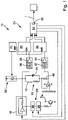
- FIG. 1 shows a first embodiment of an inductive sensor unit 10 with an LC resonant circuit 12 for determining the distance of a metallic object.
- the sensor unit 10 has the resonant circuit 12, an oscillator amplifier 18, an adjustable current source 20 with a function generator 21 for applying a test current as an excitation signal to the sensor unit 10, an evaluation unit 22 and a switching device 24 with an interface 25.
- the oscillating circuit has a capacitor 14, a sensor coil 16 with an inductance L and an effective resistance R s . Losses in the oscillating circuit are compensated for by the oscillator amplifier 18, so that the oscillating circuit oscillates at its resonant frequency during operation.
- the evaluation unit 22 has a rectifier 26 for determining the amplitude and a comparator 28, the comparator 28 providing a distance signal S A via a transistor stage.
- Switching unit 24 has a first lock-in amplifier 30, a second lock-in amplifier 32 and a computing unit 34, with first lock-in amplifier 30 measuring the voltage drop caused by the test current across effective resistance R s and inductance L measures and the second lock-in amplifier 32 measures the voltage drop across the current measuring resistor 40 caused by the test current.
- the test current preferably has a low frequency, e.g. 100 Hz, in particular significantly lower than the resonant frequency of the oscillating circuit 12.
- the voltage applied to the oscillating circuit 12 is applied to an input of the first lock-in amplifier 30 via a bandpass filter 36 for filtering out the oscillator oscillation and an amplifier 38 and is broken down by the lock-in amplifier 30 into a real part and an imaginary part.
- the test current is measured via a current measuring resistor 40 .
- the current measuring resistor 40 is in turn connected via a bandpass filter 42 and an amplifier 44 to an input of the second lock-in amplifier 32 and the measured voltage is broken down by the lock-in amplifier 32 into a real part and an imaginary part.
- Arithmetic unit 34 is designed to use the real and imaginary parts of lock-in amplifiers 30 and 32 to calculate an actual value I of inductance L of sensor coil 16 and/or an actual value I of effective resistance R s of sensor coil 16 and/or an actual value I of the inductance L or to determine the actual value I of the effective resistance R s in a functional context derived variable.
- the determined actual values are also used for compensation purposes, that is, to compensate for temperature-related changes in the inductance, as far as this is possible.
- the arithmetic unit 34 is also designed to derive a compensation from the determined actual values and to adjust or regulate the oscillator amplifier 18 and/or the rectifier 26 and/or the comparator 28 accordingly (shown in broken lines).
- the sensor unit 10 does not have an LC swinging circuit 12 .
- the sensor coil 16 with the impedance L and the effective resistance R s is connected via a transistor Q1 and a resistor R3 for a time interval T 1 to a voltage source V+ as an excitation signal and for a subsequent time interval T 2 by means of the transistor Q1 again from the voltage source V+ Cut.
- the corresponding control signal V pulse of the transistor Q1 is in section b of figure 2 shown as a function of time t.
- the self-inductance of the sensor coil 16 results in a self-inductive voltage pulse. If the metallic object is in the vicinity of the sensor unit 10, the eddy currents induced in the object generate a voltage pulse response superimposed on the self-induction voltage pulse in the sensor coil 16.
- the time profile of the voltage U 2 at the sensor coil 16 with (dashed line) and without (solid line) the subject is shown in section c figure 2 shown.
- sensor unit 10 also has a damping resistor R4, a diode D2 that limits the coil voltage, and an amplification circuit 50.
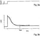
- a voltage U 3 of the sensor coil 16 that can be tapped off after the amplification circuit 50 is shown in FIG figure 3 (below) along with the control signal of transistor Q1 (above). The difference in the voltage curves with (dashed) and without (solid line) a metallic object can be seen.
- the point in time t start shows an example of a starting point in time for scanning the curve of the voltage U 3 in order to determine the distance from the object.
- circuit unit 24 for determining an actual value of the inductance of the sensor coil has arithmetic unit 34, with arithmetic unit 34 receiving at least sampled values of voltage U 2 of sensor coil 16 and a voltage U 1 upstream of resistor R3.
- the sensor unit 10 has an additional sensor 54 (dashed).
- a temperature sensor is thermally coupled to sensor coil 16 as an additional sensor 54 , computing unit 34 being designed to read temperature sensor 54 and provide the actual temperature or a variable derived from the actual temperature via interface 25 .
- the circuit unit 24 is designed to sample the voltages U 1 and U 2 in the time interval T 1 .
- the arithmetic unit 34 is also designed to provide the determined actual values I or a variable derived from one or more actual values I, e.g. by comparison with a target value, by means of the interface 25.
Landscapes
- Physics & Mathematics (AREA)
- General Physics & Mathematics (AREA)
- Engineering & Computer Science (AREA)
- Remote Sensing (AREA)
- Life Sciences & Earth Sciences (AREA)
- Electromagnetism (AREA)
- Environmental & Geological Engineering (AREA)
- Geology (AREA)
- General Life Sciences & Earth Sciences (AREA)
- Geophysics (AREA)
- Measurement Of Length, Angles, Or The Like Using Electric Or Magnetic Means (AREA)
Abstract
Description
- Die Erfindung betrifft eine induktive Sensoreinheit zum Ermitteln eines Abstands zu einem metallischen Gegenstand.
- Eine induktive Sensoreinheit in Form eines Näherungsschalters ist aus der
DE 10 2017 128 472 A1 bekannt. Der Näherungsschalter weist einem Schwingkreis mit einer Sensorspule und einem Kondensator auf, wobei während des Betriebs ein Ist-Wert der Induktivität der Sensorspule des Schwingkreises gemessen, z.B. mittels eines Lock-In-Verstärkers, und die Sensoreinheit, also z.B. der Schwingkreis, der Oszillatorverstärker und/oder die Ausgangsstufe, in Abhängigkeit von der gemessenen Induktivität eingestellt wird. Hierdurch wird der Einfluss temperaturbedingter Induktivitätsänderungen der Sensorspule auf den Schaltabstand reduziert oder sogar vollständig kompensiert. - Eine weitere induktive Sensoreinheit mit Kompensation temperaturbedingter Induktivitätsänderungen ist aus der
DE 10 2017 130 122 A1 bekannt. Die Sensoreinheit weist eine Sensorspule, aber keinen LC-Schwingkreis auf und arbeitet nach dem sogenannten Pulsauswerteverfahren. Die Sensorspule wird während eines Anregungszeitraums mit einem Strompuls angeregt und während eines sich anschließenden Sperrzeitraums von der Stromquelle getrennt. Um eine Änderung der Induktivität und / oder des Wirkwiderstands der Sensorspule zu ermitteln, wird der Strom oder die Spannung an der Sensorspule bereits während des Anregungszeitraums abgetastet. Ermittelte Änderungen werden zur Kompensation eines während des Sperrzeitraums abgetasteten Impulsantwortsignals zur Abstandsermittlung verwendet. - Aus der
EP 0 049 304 A1 , derEP 0 813 306 B1 und derDE 10 2013 202 573 B3 sind weitere gattungsgemäße Sensoreinheiten bekannt. - Aus der
DE 20 2011 001 009 U1 wird anhand einer Messung der Spulengüte und eines Vergleichs mit einem Ist-Wert ein Diagnose- bzw. Warnsignal erzeugt und ausgegeben. - Aus der
DE 10 2009 046 691 B4 ist ein Sensorgerät mit einem Diagnosegerät bekannt, wobei mittels des Sensorgerätes dem Diagnosegerät Diagnosesignale zur Auswertung bereitgestellt werden. - Aus der
DE 10 145 669 A1 ist eine induktive Sensoreinheit mit einem zusätzlichen Temperaturfühler sowie einem entsprechenden Ausgangsanschluss für ein Temperatursignal bekannt. - Vor diesem Hintergrund besteht die Aufgabe der Erfindung darin, eine Vorrichtung anzugeben, die den Stand der Technik weiterbildet.
- Die Aufgabe wird durch eine induktive Sensoreinheit mit den Merkmalen des Patentanspruchs 1 gelöst. Vorteilhafte Ausgestaltungen der Erfindung sind Gegenstand von Unteransprüchen.
- Gemäß dem Gegenstand der Erfindung wird eine induktive Sensoreinheit zum Erfassen eines Abstandes zu einem metallischen Gegenstand bereitgestellt, aufweisend eine Sensorspule, wobei die Sensorspule eine Induktivität und einen Wirkwiderstand aufweist und die Sensorspule mit einem Anregungssignal beaufschlagt ist.
- Des Weiteren weist die Sensoreinheit eine Auswerteeinheit zum Ermitteln des Abstands auf, wobei die Auswerteeinheit in Abhängigkeit der Ermittlung ein Auswertesignal bereitstellt.
- Die Sensoreinheit weist auch eine Schaltungseinheit auf. Die Schaltungseinheit ist eingerichtet einen Istwert der Induktivität der Sensorspule und / oder eines Istwerts des Wirkwiderstands der Sensorspule und/oder eine zu dem Istwert der Induktivität oder zu dem Istwert des Wirkwiderstands in einem funktionalen Zusammenhang stehende abgeleitete Größe zu bestimmen.
- Außerdem weist die Sensoreinheit eine Schnittstelle auf, um mittels der Schnittstelle zusätzlich zu dem Auswertesignal den Istwert des Wirkwiderstandes und / oder den Istwert der Induktivität und / oder die abgeleitete Größe bereitzustellen.
- Das Grundprinzip einer induktiven Sensoreinheit beruht auf einer Änderung der Induktivität bzw. der Güte der Sensorspule bei Annäherung eines metallischen Gegenstands.
- Die Sensorspule bildet beispielsweise zusammen mit einem Kondensator einen Schwingkreis (LCR-Oszillator), wobei der Schwingkreis mittels eines Oszillatorverstärkers bei einer Resonanzfrequenz betrieben wird.
- Alternativ wird die Sensorspule mittels eines Strompulses bzw. periodisch wiederkehrender Strompulse angeregt und nach dem sogenannten Pulsauswerteverfahren ausgewertet.
- Das mittels des Strompulses oder der Schwingung des Schwingkreises von der Spule erzeugte Magnetfeld induziert ab einem ausreichend geringen Abstand eines sich nähernden metallischen Gegenstands Wirbelströme in dem Gegenstand.
- Die induzierten Wirbelströme führen aufgrund der magnetischen Kopplung zwischen dem metallischen Gegenstand und dem Schwingkreis bzw. der Spule zu einer Änderung der Frequenz und / oder der Amplitude des Schwingkreises bzw. des von der Spule empfangenen Pulsantwortsignals. Anders ausgedrückt der Selbstinduktions-Spannungspuls der durch den einzelnen Spannungspuls angeregten Sensorspule wird verändert.
- Anhand der Änderung lässt sich zumindest die Anwesenheit des metallischen Objekts und / oder die Art des metallischen Objekts und / oder der Abstand des metallischen Objekts und / oder das Erreichen eines Schaltabstands ermitteln.
- Eine Änderung der Induktivität der Sensorspule und / oder des Wirkwiderstands der Spule, die zu einer Änderung der Schwingkreisamplitude und / oder -frequenz bzw. zu einer Änderung der Spulenspannung führt, wird auch durch andere Einflüsse verursacht, z.B. durch Temperaturänderungen, durch die Auswirkung mechanischer Belastungen wie insbesondere Kernbruch und Magnetostriktion, sowie Desakkommodation und externe Magnetfelder.
- Ein Vorteil ist, dass sich auf Basis einer zusätzlichen vom Objektabstand weitestgehend unabhängigen Messung der Induktivität und / oder des Wirkwiderstands der Sensorspule durchführen lässt, um insbesondere die Verfälschung der Abstandsmessung durch die vorgenannt beschriebenen anderen Einflüsse besonders vorteilhaft zu korrigieren.
- Zum anderen stellen die Induktivität oder der Wirkwiderstand der Sensorspule bzw. daraus abgeleitete Größen Messwerte dar, die für weitere über die eigentliche Aufgabe der Objekterfassung hinausgehende Auswertungen nützlich sind.
- Erfindungsgemäß ist die Schaltungseinheit daher dazu ausgelegt, die Induktivität und / oder den Wirkwiderstand der Sensorspule zu überwachen, d.h. einmal oder mehrmals einen Istwert der Induktivität und / oder des Wirkwiderstands und / oder einer zu diesen Werten in einem funktionalen Zusammenhang stehenden abgeleiteten Größe zu ermitteln und diese mittels einer Schnittstelle bereitzustellen.
- Es zeigte sich, dass sich die in einer Anlage verbaute induktive Sensoreinheit z.B. zusätzlich als Temperatursensor verwenden lässt. Gerade bei niedrigen Frequenzen ist der gemessene Wirkwiderstand der Spule proportional zur Spulentemperatur.
- Ein weiterer Vorteil ist, dass insbesondere wenn mehrere erfindungsgemäße Sensoreinheiten in einer Anlage verbaut sind, ein Betreiber von Anlagen auf einfache Welse ein Temperaturprofil seiner Anlage erstellen kann, ohne dazu zusätzliche separate Temperatursensoren installieren zu müssen.
- Hieraus ergeben sich erhebliche Kostenersparnisse, ein reduzierter Verkabelungsaufwand sowie ein reduzierter Platzbedarf, welcher gerade bei beengten Verhältnissen vorteilhaft ist.
- Darüber hinaus liefern Änderungen der Induktivität der Sensorspule beispielsweise Hinweise auf mechanische Belastungen, hohe Temperaturen oder starke Magnetfelder im Bereich der induktiven Sensoreinheit.
- Ein weiterer Vorteil ist, dass sich beispielsweise durch Computeralgorithmen die die Messwerte automatisiert analysiert und für eine Zustandsüberwachung der Anlage verwendet lassen.
- Die Sensoreinheit weist beispielsweise eine modulierte Stromquelle zum Einprägen eines Teststroms in den Schwingkreis und einen Lock-In-Verstärker zum Zerlegen des Stromabfalls an einem Strommesswiderstand in einen Real- und Imaginärteil auf.
- Alternativ wird der Strom bzw. die Spannung an den beiden Enden der durch Strompulse angeregten Sensorspule abgegriffen.
- In einer Ausführungsform weisen die Schaltungseinheit und die Auswerteeinheit jeweils eine eigene Recheneinheit auf. Alternativ werden die Schaltungseinheit und die Auswerteeinheit zumindest in Teilen durch dieselbe Recheneinheit ausgebildet.
- Der Wirkwiderstand der Sensorspule ändert sich beispielsweise sowohl aufgrund einer temperaturbedingten Änderung der Leitfähigkeit als auch aufgrund eines Litzendrahtbruchs, z.B. durch Alterung oder durch mechanische Beanspruchung. Die Induktivität ändert sich beispielsweise bei einem Bruch oder einer Magnetostriktion des Ferritkerns, z.B. aufgrund mechanischer Beanspruchung.
- Die Schnittstelle dient entsprechend der weiteren Auswertung und / oder Überwachung, z.B. lässt sich das bereitgestellte Signal auswerten und gegebenenfalls mittels eines Warnsignals auf aktuelle Probleme hinweisen. Gemäß einer anderen Ausführungsform werden die via der Schnittstelle bereitgestellten Ist-Werte aufgezeichnet und beispielsweise zu Wartungszwecken herangezogen.
- In einer Ausführungsform ist die Schnittstelle eingerichtet, den Istwert des Wirkwiderstands und / oder den Istwert der Induktivität und / oder die abgeleitete Größe analog und / oder digital bereitzustellen.
- In einer anderen Ausführungsform ist die Schaltungseinheit dazu ausgelegt, an mehreren Zeitpunkten aus dem Verlauf der Spulenspannung oder des Spulenstroms Istwerte zu bestimmen. So kann der zeitliche Verlauf der Ist-Werte überwacht bzw. zu Auswertezwecken, insbesondere zur Störungsanalyse, herangezogen werden.
- In einer weiteren Ausführungsform ist die Schaltungseinheit ausgelegt, den Wirkwiderstand und / oder die Induktivität und / oder die abgeleitete Größe aus dem zeitlichen Verlauf der Spulenspannung zu bestimmen.
- In einer anderen Weiterbildung umfasst das Signal einzelne zeitlich voneinander beabstandete Pulse oder eine Schwingung.
- Gemäß einer anderen Ausführungsform ist eine Pulsfrequenz zur Bestimmung des Wirkwiderstandes und / oder der Induktivität identisch mit der Pulsfrequenz zur Bestimmung des Objektabstandes.
- Alternativ unterscheidet sich die Pulsfrequenz zur Bestimmung des Wirkwiderstands und der Induktivität von der Pulsfrequenz zur Bestimmung des Objektabstands.
- Gemäß einer weiteren Weiterbildung weist die induktive Sensoreinheit einen zusätzlichen Sensor auf und die Schaltungseinheit ist dazu ausgelegt, ein Sensorsignal des zusätzlichen Sensors zu empfangen und das Sensorsignal oder ein weiterverarbeitetes Sensorsignal über die Schnittstelle auszugeben.
- In einer anderen Ausführungsform umfasst der zusätzliche Sensor einen Temperatursensor und der Temperatursensor erfasst die Temperatur am Ort der Sensorspule.
- Gemäß einer weiteren Ausführungsform ist die Sensorspule mit der Auswerteeinheit mittels eines Kabels verschaltet und das Kabel weist eine Länge zwischen mindestens 1 m und maximal 50 m auf. Alternativ beträgt die Länge zwischen 5 m und 20 m.
- Die Erfindung wird nachfolgend unter Bezugnahme auf die Zeichnungen näher erläutert. Hierbei werden gleichartige Teile mit identischen Bezeichnungen beschriftet. Die dargestellten Ausführungsformen sind stark schematisiert, d.h. die Abstände und die lateralen und die vertikalen Erstreckungen sind nicht maßstäblich und weisen, sofern nicht anders angegeben, auch keine ableitbaren geometrischen Relationen zueinander auf. Darin zeigen, die
- Figur 1
- eine Ansicht auf eine erste Ausführungsform,
- Figur 2
- eine Ansicht auf eine zweite Ausführungsform,
- Figur 3
- einen beispielhaften Verlauf einer Schalt- und einer Sensorspulenspannung.
- Die Abbildung der
Figur 1 zeigt eine erste Ausführungsform einer induktiven Sensoreinheit 10 mit einem LC-Schwingkreis 12 zur Abstandsbestimmung eines metallischen Objekts. Die Sensoreinheit 10 weist den Schwingkreis 12, einen Oszillatorverstärker 18, eine einstellbare Stromquelle 20 mit einem Funktionsgenerator 21 zur Beaufschlagung der Sensoreinheit 10 mit einem Teststrom als Anregungssignal, einer Auswerteeinheit 22 und einer Schalteinrichtung 24 mit einer Schnittstelle 25. - Der Schwingkreis weist einen Kondensator 14, eine Sensorspule 16 mit einer Induktivität L und einen Wirkwiderstand Rs auf. Verluste des Schwingkreises werden durch den Oszillatorverstärker 18 ausgeglichen, so dass der Schwingkreis im Betrieb mit seiner Resonanzfrequenz schwingt.
- Die Auswerteeinheit 22 weist in dem dargestellten Ausführungsbeispiel eine Gleichrichter 26 zur Amplitudenbestimmung und einen Komparator 28 auf, wobei der Komparator 28 ein Abstandssignal SA über eine Transistorstufe bereitstellt.
- Die Schalteinheit 24 weist einen ersten Lock-In-Verstärker 30, einen zweiten Lock-In-Verstärker 32 und eine Recheneinheit 34 auf, wobei der erste Lock-In-Verstärker 30 den vom Teststrom verursachten Spannungsabfall über den Wirkwiderstand Rs und der Induktivität L misst und der zweite Lock-In-Verstärker 32 den vom Teststrom verursachten Spannungsabfall über den Strommesswiderstand 40 misst.
- Damit die Bestimmung der Induktivität L bzw. des Wirkwiderstands Rs unabhängig von dem metallischen Objekts bzw. dessen Bewegung ist, weist der Teststrom bevorzugt eine niedrige Frequenz, z.B. 100 Hz, insbesondere deutlich niedriger als die Resonanzfrequenz des Schwingkreises 12.
- Die an dem Schwingkreis 12 anliegende Spannung wird über einen Bandpassfilter 36 zum Herausfiltern der Oszillatorschwingung und einen Verstärker 38 auf einen Eingang des ersten Lock-In-Verstärkers 30 gelegt und mittels des Lock-In-Verstärkers 30 in einen Realteil und einen Imaginärteil zerlegt.
- Über einen Strommesswiderstand 40 wird der Teststrom gemessen. Hierfür ist der Strommesswiderstand 40 wiederum über einen Bandpassfilter 42 und einen Verstärker 44 mit einem Eingang des zweiten lock-In-Verstärkers 32 verbunden und die gemessene Spannung wird mittels des Lock-In-Verstärkers 32 in einen Realteil und einen Imaginärteil zerlegt.
- Die Recheneinheit 34 ist dazu ausgelegt anhand der Real- und Imaginärteile der Lock-In-Verstärker 30 und 32 einen Istwert I der Induktivität L der Sensorspule 16 und / oder einen Istwert I des Wirkwiderstands Rs der Sensorspule 16 und/oder eine zu dem Istwert I der Induktivität L oder zu dem Istwert I des Wirkwiderstands Rs in einem funktionalen Zusammenhang stehende abgeleitete Größe zu ermitteln.
- In einer optionalen Weiterbildung werden die ermittelten Istwerte zusätzlich zu Kompensationszwecken genutzt, also zum Ausgleich von beispielsweise temperaturbedingten Änderungen der Induktivität, soweit dies möglich ist. Beispielsweise ist die Recheneinheit 34 auch dazu ausgelegt aus den ermittelten Istwerten eine Kompensation abzuleiten und den Oszillatorverstärker 18 und / oder den Gleichrichter 26 und / oder den Komparator 28 gegebenenfalls entsprechend einzustellen bzw. zu regeln (gestrichelt dargestellt).
- In der Abbildung der
Figur 2 ist eine weitere erfindungsgemäße Ausführungsform der Sensoreinheit 10 dargestellt. Im Folgenden werden nur die Unterschiede zu der Abbildung derFigur 1 erläutert. - Im Unterschied zu der ersten Ausführungsform weist die Sensoreinheit 10 gemäß der weiten Ausführungsform keinen LC-Schwingreis 12 auf. Die Sensorspule 16 mit der Impedanz L und dem Wirkwiderstand Rs wird über einen Transistors Q1 und einen Widerstand R3 für ein Zeitintervall T1 mit einer Spannungsquelle V+ als Anregungssignal verbunden und für ein sich anschließendes Zeitintervall T2 mittels des Transistors Q1 wieder von der Spannungsquelle V+ getrennt. Das entsprechende Steuersignal VPuls des Transistors Q1 ist in Abschnitt b der
Figur 2 als Funktion der Zeit t dargestellt. - Nach dem Trennen der Sensorspule 16 von der Spannungsquelle V+ führt die Selbstinduktion der Sensorspule 16 zu einem Selbstinduktions-Spannungspuls. Befindet sich der metallische Gegenstand in der Nähe der Sensoreinheit 10, so erzeugen die in dem Gegenstand induzierten Wirbelströme eine den Selbstinduktions-Spannungspuls überlagernde Spannungspulsantwort in der Sensorspule 16. Der zeitliche Verlauf der Spannung U2 an der Sensorspule 16 mit (gestrichelt) und ohne (durchgezogene Linie) Gegenstand ist in Abschnitt c der
Figur 2 dargestellt. - In dem dargestellten Ausführungsbeispiel weist die Sensoreinheit 10 außerdem einen Bedämpfungswiderstand R4, eine die Spulenspannung limitierende Diode D2 und eine Verstärkungsschaltung 50 auf. Eine nach der Verstärkungsschaltung 50 abgreifbare Spannung U3 der Sensorspule 16 ist in der Abbildung der
Figur 3 (unten) zusammen mit dem Steuersignal des Transistors Q1 (oben) dargestellt. Der Unterschied der Spannungsverläufe mit (gestrichelt) und ohne (durchgezogenen Linie) metallischen Gegenstand ist zu erkennen. Der Zeitpunkt tstart zeigt beispielhaft einen Anfangszeitpunkt für ein Abtasten des Verlaufs der Spannung U3, um den Abstand des Objekts zu ermitteln. - Die Schaltungseinheit 24 zum Bestimmen eines Istwerts der Induktivität der Sensorspule weist in dem dargestellten Ausführungsbeispiel die Recheneinheit 34 auf, wobei die Recheneinheit 34 zumindest Abtastwerte der Spannung U2 der Sensorspule 16 und einer Spannung U1 vor dem Widerstand R3 empfängt.
- Optional weist die Sensoreinheit 10 einen zusätzlichen Sensor 54 (gestrichelt) auf. Beispielsweise ist als zusätzlicher Sensor 54 ein Temperatursensor thermisch mit der Sensorspule 16 gekoppelt, wobei die Recheneinheit 34 dazu ausgelegt ist, den Temperatursensor 54 auszulesen und die Ist-Temperatur oder eine von der Ist-Temperatur abgeleitete Größe mittels der Schnittstelle 25 bereitzustellen.
- Damit die Bestimmung der Induktivität L bzw. des Wirkwiderstands Rs weitestgehend unabhängig von dem metallischen Objekts bzw. dessen Bewegung ist, ist die Schaltungseinheit 24 dazu ausgelegt, die Spannungen U1 und U2 in dem Zeitinterwall T1 abzutasten.
- Wie aus dem Schaltbild im Abschnitt a der
Figur 2 hervorgeht, gilt für den Strom durch die Sensorspule 16 IL = IR3 - IRT, wobei mit RT ein sich aus der weiteren Schaltung, insbesondere R4, ergebender effektiver Bedämpfungswiderstand bezeichnet wird. Für den Spannungsabfall über der Sensorspule 16 gilt U2 - V- = L dIL/dt + RS IL. - Am Ende des Zeitintervalls T1 zu einem Zeitpunkt tconst stellt sich ein im Wesentlich konstanter Strom durch die Sensorspule ein, so dass für den Wirkwiderstand RS zum Zeitpunkt tconst näherungsweise gilt RS = (U2 - V.) / IL. Mittels der Näherung kann somit der Istwert I des Wirkwiderstand RS zum Zeitpunkt tconst und anschließend auch der Istwert I der Induktivität L bestimmt werden, z.B. mittels eines Fit des gemessenen Verlaufs der Spannung U2 mit der Methode der kleinsten Quadrate.
- Die Recheneinheit 34 ist außerdem dazu ausgelegt, die ermittelten Istwerte I oder eine aus einem oder mehreren Istwerten I abgeleitete Größe, z.B. durch Vergleich mit einem Sollwert, mittels der Schnittstelle 25 bereitzustellen.
Claims (8)
- Induktive Sensoreinheit (10) zum Erfassen eines Abstands zu einem metallischen Gegenstand, aufweisend- eine Sensorspule (16), wobei die Sensorspule (16) eine Induktivität (L) und einen Wirkwiderstand (RS) aufweist, und die Sensorspule (16) mit einem Anregungssignal beaufschlagt ist,- eine Auswerteeinheit (22) zum Ermitteln des Abstands, wobei die Auswerteeinheit (22) in Abhängigkeit der Ermittlung ein Auswertesignal bereitstellt,- einer Schaltungseinheit (24) zum Bestimmen eines Istwerts (I) der Induktivität (L) der Sensorspule (16) und / oder eines Istwerts (I) des Wirkwiderstands (RS) der Sensorspule (16) und/oder eine zu dem Istwert (I) der Induktivität (L) oder zu dem Istwert (I) des Wirkwiderstands (RS) in einem funktionalen Zusammenhang stehende abgeleitete Größe,dadurch gekennzeichnet, dass
die Sensoreinheit (10) eine Schnittstelle (25) aufweist, um mittels der Schnittstelle (25) zusätzlich zu dem Auswertesignal den Istwert (I) des Wirkwiderstandes und / oder den Istwert (I) der Induktivität (L) und / oder die abgeleitete Größe bereitzustellen. - Induktive Sensoreinheit (10) nach Anspruch 1, dadurch gekennzeichnet, dass die Schnittstelle (25) eingerichtet ist, den Istwert (I) des Wirkwiderstands (RS) und / oder den Istwert (I) der Induktivität (L) und / oder die abgeleitete Größe analog und / oder digital bereitzustellen.
- Induktive Sensoreinheit (10) nach Anspruch 1 oder Anspruch 2, dadurch gekennzeichnet, dass die Schaltungseinheit (24) dazu ausgelegt ist, an mehreren Zeitpunkten aus dem Verlauf der Spulenspannung oder des Spulenstroms Istwerte (I) zu bestimmen.
- Induktive Sensoreinheit (10) nach Anspruch 3, dadurch gekennzeichnet, dass die Schaltungseinheit (24) ausgelegt ist, den Wirkwiderstand (RS) und / oder die Induktivität (L) und / oder die abgeleitete Größe aus dem zeitlichen Verlauf der Spulenspannung zu bestimmen.
- Induktive Sensoreinheit (10) nach einem der vorstehenden Ansprüche 1, dadurch gekennzeichnet, dass das Anregungssignal einzelne zeitlich voneinander beabstandete Pulse oder eine Schwingung umfasst.
- Induktive Sensoreinheit (10) nach einem der vorstehenden Ansprüche, dadurch gekennzeichnet, dass die induktive Sensoreinheit (10) einen zusätzlichen Sensor (54) aufweist und die Schaltungseinheit (24) dazu ausgelegt ist, ein Sensorsignal des zusätzlichen Sensors (54) zu empfangen und das Sensorsignal oder ein weiterverarbeitetes Sensorsignal über die Schnittstelle (25) auszugeben.
- Induktive Sensoreinheit (10) nach einem der vorstehenden Ansprüche, dadurch gekennzeichnet, dass der zusätzliche Sensor (54) einen Temperatursensor umfasst und der Temperatursensor die Temperatur am Ort der Sensorspule (16) erfasst.
- Induktive Sensoreinheit (10) nach einem der vorstehenden Ansprüche, dadurch gekennzeichnet, dass die Sensorspule (16) mit der Auswerteeinheit (22) mittels eines Kabels verschaltet ist und das Kabel eine Länge von mindestens 1 m und maximal 50 m aufweist.
Applications Claiming Priority (1)
| Application Number | Priority Date | Filing Date | Title |
|---|---|---|---|
| DE102021000158.3A DE102021000158A1 (de) | 2021-01-15 | 2021-01-15 | Induktive Sensoreinheit |
Publications (2)
| Publication Number | Publication Date |
|---|---|
| EP4030135A1 true EP4030135A1 (de) | 2022-07-20 |
| EP4030135B1 EP4030135B1 (de) | 2023-07-05 |
Family
ID=79287758
Family Applications (1)
| Application Number | Title | Priority Date | Filing Date |
|---|---|---|---|
| EP22000004.6A Active EP4030135B1 (de) | 2021-01-15 | 2022-01-04 | Induktive sensoreinheit |
Country Status (2)
| Country | Link |
|---|---|
| EP (1) | EP4030135B1 (de) |
| DE (1) | DE102021000158A1 (de) |
Citations (13)
| Publication number | Priority date | Publication date | Assignee | Title |
|---|---|---|---|---|
| EP0049304A1 (de) | 1980-10-07 | 1982-04-14 | Micro-Epsilon Messtechnik GmbH & Co. Kommanditgesellschaft | Verfahren zur Kompensation von temperaturbedingten Messfehlern bei Wechselstrom-Messschaltungen, insbesondere Abstandsmessgeräten sowie Vorrichtung zur Durchführung des Verfahrens |
| EP0813306B1 (de) | 1996-06-13 | 2001-10-04 | Optosys SA | Temperaturstabilisierter Oszillator und Verwendung desselben in einem Näherungsschalter |
| DE10145669A1 (de) | 2001-09-11 | 2003-03-27 | Balluff Gmbh | Abstandssensor und Auswerteeinrichtung-Abstandssensor-Kombination |
| US20100225332A1 (en) * | 2007-09-20 | 2010-09-09 | Masahisa Niwa | Proximity sensor |
| DE102009052467B3 (de) * | 2009-11-09 | 2011-07-14 | Sick Ag, 79183 | Induktiver Näherungssensor mit Temperaturkompensation |
| DE202011001009U1 (de) | 2011-04-29 | 2012-07-31 | Mel Mikroelektronik Gmbh | Sensorsystem mit induktivem Näherungsschalter |
| DE102009046691B4 (de) | 2009-11-13 | 2013-06-06 | Balluff Gmbh | Sensorvorrichtung |
| DE102013202573B3 (de) | 2013-02-18 | 2014-04-17 | Ifm Electronic Gmbh | Induktiver Näherungsschalter |
| DE102015216651A1 (de) * | 2015-09-01 | 2017-03-02 | Ifm Electronic Gmbh | Induktiver Näherungsschalter mit einem Mikrocontroller |
| DE102017130122A1 (de) | 2017-03-15 | 2018-09-20 | Omron Corporation | Annäherungssensor und Erfassungsverfahren |
| DE102018103239A1 (de) * | 2017-09-25 | 2019-03-28 | Omron Corporation | Näherungssensor |
| DE102017128471A1 (de) * | 2017-11-30 | 2019-06-06 | Pepperl + Fuchs Gmbh | Induktiver Näherungsschalter und Verfahren zum Betreiben eines induktiven Näherungsschalters |
| DE102017128472A1 (de) | 2017-11-30 | 2019-06-06 | Pepperl + Fuchs Gmbh | Induktiver Näherungsschalter und Verfahren zum Betreiben eines induktiven Näherungsschalters |
Family Cites Families (1)
| Publication number | Priority date | Publication date | Assignee | Title |
|---|---|---|---|---|
| DE4141065A1 (de) | 1991-12-13 | 1993-06-17 | Vdo Schindling | Verfahren zur temperaturkompensation von induktiven sensoren |
-
2021
- 2021-01-15 DE DE102021000158.3A patent/DE102021000158A1/de not_active Withdrawn
-
2022
- 2022-01-04 EP EP22000004.6A patent/EP4030135B1/de active Active
Patent Citations (13)
| Publication number | Priority date | Publication date | Assignee | Title |
|---|---|---|---|---|
| EP0049304A1 (de) | 1980-10-07 | 1982-04-14 | Micro-Epsilon Messtechnik GmbH & Co. Kommanditgesellschaft | Verfahren zur Kompensation von temperaturbedingten Messfehlern bei Wechselstrom-Messschaltungen, insbesondere Abstandsmessgeräten sowie Vorrichtung zur Durchführung des Verfahrens |
| EP0813306B1 (de) | 1996-06-13 | 2001-10-04 | Optosys SA | Temperaturstabilisierter Oszillator und Verwendung desselben in einem Näherungsschalter |
| DE10145669A1 (de) | 2001-09-11 | 2003-03-27 | Balluff Gmbh | Abstandssensor und Auswerteeinrichtung-Abstandssensor-Kombination |
| US20100225332A1 (en) * | 2007-09-20 | 2010-09-09 | Masahisa Niwa | Proximity sensor |
| DE102009052467B3 (de) * | 2009-11-09 | 2011-07-14 | Sick Ag, 79183 | Induktiver Näherungssensor mit Temperaturkompensation |
| DE102009046691B4 (de) | 2009-11-13 | 2013-06-06 | Balluff Gmbh | Sensorvorrichtung |
| DE202011001009U1 (de) | 2011-04-29 | 2012-07-31 | Mel Mikroelektronik Gmbh | Sensorsystem mit induktivem Näherungsschalter |
| DE102013202573B3 (de) | 2013-02-18 | 2014-04-17 | Ifm Electronic Gmbh | Induktiver Näherungsschalter |
| DE102015216651A1 (de) * | 2015-09-01 | 2017-03-02 | Ifm Electronic Gmbh | Induktiver Näherungsschalter mit einem Mikrocontroller |
| DE102017130122A1 (de) | 2017-03-15 | 2018-09-20 | Omron Corporation | Annäherungssensor und Erfassungsverfahren |
| DE102018103239A1 (de) * | 2017-09-25 | 2019-03-28 | Omron Corporation | Näherungssensor |
| DE102017128471A1 (de) * | 2017-11-30 | 2019-06-06 | Pepperl + Fuchs Gmbh | Induktiver Näherungsschalter und Verfahren zum Betreiben eines induktiven Näherungsschalters |
| DE102017128472A1 (de) | 2017-11-30 | 2019-06-06 | Pepperl + Fuchs Gmbh | Induktiver Näherungsschalter und Verfahren zum Betreiben eines induktiven Näherungsschalters |
Also Published As
| Publication number | Publication date |
|---|---|
| EP4030135B1 (de) | 2023-07-05 |
| DE102021000158A1 (de) | 2022-07-21 |
Similar Documents
| Publication | Publication Date | Title |
|---|---|---|
| DE69804857T2 (de) | Integritätsprüfung von elektroden | |
| EP2028474B1 (de) | Verfahren und Vorrichtung zum Erfassen von Partikeln in einer strömenden Flüssigkeit | |
| DE3741734C2 (de) | Vorrichtung zur Messung der Induktivität einer Spule, insbesondere zur Messung der Ankerstellung eines Spulen/Anker-Magnetsystems | |
| EP2291665B1 (de) | Stromsensoranordnung zur messung von strömen in einem primärleiter | |
| DE102018104516A1 (de) | System zur Überwachung von Gebläseschwingungen | |
| EP0782692B1 (de) | Sensoranordnung und verfahren zur messwerterfassung mit der sensoranordnung | |
| EP2651036A1 (de) | Induktiver Näherungssensor | |
| EP2511736B1 (de) | Vorrichtung und Verfahren zur Detektion von elektrisch leitfähigen Gegenständen | |
| EP1792144B1 (de) | Verfahren zum überprüfen eines magnetisch-induktiven durch flussmessers | |
| DE102009022138A1 (de) | Vorrichtung und Verfahren für induktive Messungen | |
| DE102009022136A1 (de) | Vorrichtung und Verfahren für induktive Messungen | |
| EP3559604B1 (de) | Verfahren zum betreiben eines magnetisch-induktiven durchflussmessgeräts und ein solches durchflussmessgerät | |
| WO2014180649A1 (de) | Verfahren zur überwachung zumindest einer medienspezifischen eigenschaft eines mediums für eine füllstandsmessung | |
| DE3813739A1 (de) | Verfahren zum zerstoerungsfreien messen magnetischer eigenschaften eines pruefkoerpers sowie vorrichtung zum zerstoerungsfreien messen magnetischer eigenschaften eines pruefkoerpers | |
| EP2312338A1 (de) | Vorrichtung und Verfahren zur Detektion von elektrisch leitfähigen Gegenständen | |
| DE60033270T2 (de) | Vorrichtung und apparatur zur messung des pegels von flüssigem metall beim elektromagnetischen stranggiessen | |
| EP3293499B1 (de) | Verfahren zum betreiben eines magnetisch-induktiven durchflussmessgeräts und magnetisch-induktives durchflussmessgerät | |
| EP3824323B1 (de) | Detektor zum detektieren von elektrisch leitfähigem material | |
| EP4030135B1 (de) | Induktive sensoreinheit | |
| EP3314310B1 (de) | Vorrichtung und verfahren zur erfassung eines gegenstandes | |
| EP3074726B1 (de) | Induktiver messtaster und verfahren zum betreiben eines induktiven messtasters | |
| EP1873543B1 (de) | Magnetfeldkompensationssystem mit erhöhter Bandbreite | |
| EP1328777B1 (de) | Verfahren und vorrichtung zur system- und prozessüberwachung bei einem magnetisch-induktiven sensor | |
| EP4030623A1 (de) | Induktive sensoreinheit und überwachungsverfahren | |
| DE102017128472B4 (de) | Induktiver Näherungsschalter und Verfahren zum Betreiben eines induktiven Näherungsschalters |
Legal Events
| Date | Code | Title | Description |
|---|---|---|---|
| PUAI | Public reference made under article 153(3) epc to a published international application that has entered the european phase |
Free format text: ORIGINAL CODE: 0009012 |
|
| STAA | Information on the status of an ep patent application or granted ep patent |
Free format text: STATUS: THE APPLICATION HAS BEEN PUBLISHED |
|
| AK | Designated contracting states |
Kind code of ref document: A1 Designated state(s): AL AT BE BG CH CY CZ DE DK EE ES FI FR GB GR HR HU IE IS IT LI LT LU LV MC MK MT NL NO PL PT RO RS SE SI SK SM TR |
|
| STAA | Information on the status of an ep patent application or granted ep patent |
Free format text: STATUS: REQUEST FOR EXAMINATION WAS MADE |
|
| 17P | Request for examination filed |
Effective date: 20221104 |
|
| RBV | Designated contracting states (corrected) |
Designated state(s): AL AT BE BG CH CY CZ DE DK EE ES FI FR GB GR HR HU IE IS IT LI LT LU LV MC MK MT NL NO PL PT RO RS SE SI SK SM TR |
|
| GRAP | Despatch of communication of intention to grant a patent |
Free format text: ORIGINAL CODE: EPIDOSNIGR1 |
|
| STAA | Information on the status of an ep patent application or granted ep patent |
Free format text: STATUS: GRANT OF PATENT IS INTENDED |
|
| INTG | Intention to grant announced |
Effective date: 20230330 |
|
| GRAS | Grant fee paid |
Free format text: ORIGINAL CODE: EPIDOSNIGR3 |
|
| GRAA | (expected) grant |
Free format text: ORIGINAL CODE: 0009210 |
|
| STAA | Information on the status of an ep patent application or granted ep patent |
Free format text: STATUS: THE PATENT HAS BEEN GRANTED |
|
| AK | Designated contracting states |
Kind code of ref document: B1 Designated state(s): AL AT BE BG CH CY CZ DE DK EE ES FI FR GB GR HR HU IE IS IT LI LT LU LV MC MK MT NL NO PL PT RO RS SE SI SK SM TR |
|
| REG | Reference to a national code |
Ref country code: CH Ref legal event code: EP |
|
| REG | Reference to a national code |
Ref country code: AT Ref legal event code: REF Ref document number: 1585201 Country of ref document: AT Kind code of ref document: T Effective date: 20230715 |
|
| REG | Reference to a national code |
Ref country code: DE Ref legal event code: R096 Ref document number: 502022000047 Country of ref document: DE |
|
| REG | Reference to a national code |
Ref country code: IE Ref legal event code: FG4D Free format text: LANGUAGE OF EP DOCUMENT: GERMAN |
|
| REG | Reference to a national code |
Ref country code: LT Ref legal event code: MG9D |
|
| REG | Reference to a national code |
Ref country code: NL Ref legal event code: MP Effective date: 20230705 |
|
| PG25 | Lapsed in a contracting state [announced via postgrant information from national office to epo] |
Ref country code: NL Free format text: LAPSE BECAUSE OF FAILURE TO SUBMIT A TRANSLATION OF THE DESCRIPTION OR TO PAY THE FEE WITHIN THE PRESCRIBED TIME-LIMIT Effective date: 20230705 |
|
| PG25 | Lapsed in a contracting state [announced via postgrant information from national office to epo] |
Ref country code: GR Free format text: LAPSE BECAUSE OF FAILURE TO SUBMIT A TRANSLATION OF THE DESCRIPTION OR TO PAY THE FEE WITHIN THE PRESCRIBED TIME-LIMIT Effective date: 20231006 |
|
| PG25 | Lapsed in a contracting state [announced via postgrant information from national office to epo] |
Ref country code: ES Free format text: LAPSE BECAUSE OF FAILURE TO SUBMIT A TRANSLATION OF THE DESCRIPTION OR TO PAY THE FEE WITHIN THE PRESCRIBED TIME-LIMIT Effective date: 20230705 |
|
| PG25 | Lapsed in a contracting state [announced via postgrant information from national office to epo] |
Ref country code: IS Free format text: LAPSE BECAUSE OF FAILURE TO SUBMIT A TRANSLATION OF THE DESCRIPTION OR TO PAY THE FEE WITHIN THE PRESCRIBED TIME-LIMIT Effective date: 20231105 |
|
| PG25 | Lapsed in a contracting state [announced via postgrant information from national office to epo] |
Ref country code: SE Free format text: LAPSE BECAUSE OF FAILURE TO SUBMIT A TRANSLATION OF THE DESCRIPTION OR TO PAY THE FEE WITHIN THE PRESCRIBED TIME-LIMIT Effective date: 20230705 Ref country code: RS Free format text: LAPSE BECAUSE OF FAILURE TO SUBMIT A TRANSLATION OF THE DESCRIPTION OR TO PAY THE FEE WITHIN THE PRESCRIBED TIME-LIMIT Effective date: 20230705 Ref country code: PT Free format text: LAPSE BECAUSE OF FAILURE TO SUBMIT A TRANSLATION OF THE DESCRIPTION OR TO PAY THE FEE WITHIN THE PRESCRIBED TIME-LIMIT Effective date: 20231106 Ref country code: NO Free format text: LAPSE BECAUSE OF FAILURE TO SUBMIT A TRANSLATION OF THE DESCRIPTION OR TO PAY THE FEE WITHIN THE PRESCRIBED TIME-LIMIT Effective date: 20231005 Ref country code: LV Free format text: LAPSE BECAUSE OF FAILURE TO SUBMIT A TRANSLATION OF THE DESCRIPTION OR TO PAY THE FEE WITHIN THE PRESCRIBED TIME-LIMIT Effective date: 20230705 Ref country code: LT Free format text: LAPSE BECAUSE OF FAILURE TO SUBMIT A TRANSLATION OF THE DESCRIPTION OR TO PAY THE FEE WITHIN THE PRESCRIBED TIME-LIMIT Effective date: 20230705 Ref country code: IS Free format text: LAPSE BECAUSE OF FAILURE TO SUBMIT A TRANSLATION OF THE DESCRIPTION OR TO PAY THE FEE WITHIN THE PRESCRIBED TIME-LIMIT Effective date: 20231105 Ref country code: HR Free format text: LAPSE BECAUSE OF FAILURE TO SUBMIT A TRANSLATION OF THE DESCRIPTION OR TO PAY THE FEE WITHIN THE PRESCRIBED TIME-LIMIT Effective date: 20230705 Ref country code: GR Free format text: LAPSE BECAUSE OF FAILURE TO SUBMIT A TRANSLATION OF THE DESCRIPTION OR TO PAY THE FEE WITHIN THE PRESCRIBED TIME-LIMIT Effective date: 20231006 Ref country code: FI Free format text: LAPSE BECAUSE OF FAILURE TO SUBMIT A TRANSLATION OF THE DESCRIPTION OR TO PAY THE FEE WITHIN THE PRESCRIBED TIME-LIMIT Effective date: 20230705 Ref country code: ES Free format text: LAPSE BECAUSE OF FAILURE TO SUBMIT A TRANSLATION OF THE DESCRIPTION OR TO PAY THE FEE WITHIN THE PRESCRIBED TIME-LIMIT Effective date: 20230705 |
|
| PG25 | Lapsed in a contracting state [announced via postgrant information from national office to epo] |
Ref country code: PL Free format text: LAPSE BECAUSE OF FAILURE TO SUBMIT A TRANSLATION OF THE DESCRIPTION OR TO PAY THE FEE WITHIN THE PRESCRIBED TIME-LIMIT Effective date: 20230705 |
|
| REG | Reference to a national code |
Ref country code: DE Ref legal event code: R097 Ref document number: 502022000047 Country of ref document: DE |
|
| PG25 | Lapsed in a contracting state [announced via postgrant information from national office to epo] |
Ref country code: SM Free format text: LAPSE BECAUSE OF FAILURE TO SUBMIT A TRANSLATION OF THE DESCRIPTION OR TO PAY THE FEE WITHIN THE PRESCRIBED TIME-LIMIT Effective date: 20230705 Ref country code: RO Free format text: LAPSE BECAUSE OF FAILURE TO SUBMIT A TRANSLATION OF THE DESCRIPTION OR TO PAY THE FEE WITHIN THE PRESCRIBED TIME-LIMIT Effective date: 20230705 Ref country code: EE Free format text: LAPSE BECAUSE OF FAILURE TO SUBMIT A TRANSLATION OF THE DESCRIPTION OR TO PAY THE FEE WITHIN THE PRESCRIBED TIME-LIMIT Effective date: 20230705 Ref country code: DK Free format text: LAPSE BECAUSE OF FAILURE TO SUBMIT A TRANSLATION OF THE DESCRIPTION OR TO PAY THE FEE WITHIN THE PRESCRIBED TIME-LIMIT Effective date: 20230705 Ref country code: SK Free format text: LAPSE BECAUSE OF FAILURE TO SUBMIT A TRANSLATION OF THE DESCRIPTION OR TO PAY THE FEE WITHIN THE PRESCRIBED TIME-LIMIT Effective date: 20230705 |
|
| PLBE | No opposition filed within time limit |
Free format text: ORIGINAL CODE: 0009261 |
|
| STAA | Information on the status of an ep patent application or granted ep patent |
Free format text: STATUS: NO OPPOSITION FILED WITHIN TIME LIMIT |
|
| PG25 | Lapsed in a contracting state [announced via postgrant information from national office to epo] |
Ref country code: IT Free format text: LAPSE BECAUSE OF FAILURE TO SUBMIT A TRANSLATION OF THE DESCRIPTION OR TO PAY THE FEE WITHIN THE PRESCRIBED TIME-LIMIT Effective date: 20230705 |
|
| 26N | No opposition filed |
Effective date: 20240408 |
|
| PG25 | Lapsed in a contracting state [announced via postgrant information from national office to epo] |
Ref country code: SI Free format text: LAPSE BECAUSE OF FAILURE TO SUBMIT A TRANSLATION OF THE DESCRIPTION OR TO PAY THE FEE WITHIN THE PRESCRIBED TIME-LIMIT Effective date: 20230705 |
|
| PG25 | Lapsed in a contracting state [announced via postgrant information from national office to epo] |
Ref country code: MC Free format text: LAPSE BECAUSE OF FAILURE TO SUBMIT A TRANSLATION OF THE DESCRIPTION OR TO PAY THE FEE WITHIN THE PRESCRIBED TIME-LIMIT Effective date: 20230705 |
|
| PG25 | Lapsed in a contracting state [announced via postgrant information from national office to epo] |
Ref country code: MC Free format text: LAPSE BECAUSE OF FAILURE TO SUBMIT A TRANSLATION OF THE DESCRIPTION OR TO PAY THE FEE WITHIN THE PRESCRIBED TIME-LIMIT Effective date: 20230705 |
|
| PG25 | Lapsed in a contracting state [announced via postgrant information from national office to epo] |
Ref country code: LU Free format text: LAPSE BECAUSE OF NON-PAYMENT OF DUE FEES Effective date: 20240104 |
|
| PG25 | Lapsed in a contracting state [announced via postgrant information from national office to epo] |
Ref country code: LU Free format text: LAPSE BECAUSE OF NON-PAYMENT OF DUE FEES Effective date: 20240104 |
|
| PG25 | Lapsed in a contracting state [announced via postgrant information from national office to epo] |
Ref country code: BE Free format text: LAPSE BECAUSE OF NON-PAYMENT OF DUE FEES Effective date: 20240131 |
|
| PG25 | Lapsed in a contracting state [announced via postgrant information from national office to epo] |
Ref country code: BE Free format text: LAPSE BECAUSE OF NON-PAYMENT OF DUE FEES Effective date: 20240131 |
|
| REG | Reference to a national code |
Ref country code: BE Ref legal event code: MM Effective date: 20240131 |
|
| PG25 | Lapsed in a contracting state [announced via postgrant information from national office to epo] |
Ref country code: BG Free format text: LAPSE BECAUSE OF FAILURE TO SUBMIT A TRANSLATION OF THE DESCRIPTION OR TO PAY THE FEE WITHIN THE PRESCRIBED TIME-LIMIT Effective date: 20230705 |
|
| PG25 | Lapsed in a contracting state [announced via postgrant information from national office to epo] |
Ref country code: BG Free format text: LAPSE BECAUSE OF FAILURE TO SUBMIT A TRANSLATION OF THE DESCRIPTION OR TO PAY THE FEE WITHIN THE PRESCRIBED TIME-LIMIT Effective date: 20230705 |
|
| PG25 | Lapsed in a contracting state [announced via postgrant information from national office to epo] |
Ref country code: IE Free format text: LAPSE BECAUSE OF NON-PAYMENT OF DUE FEES Effective date: 20240104 |
|
| PG25 | Lapsed in a contracting state [announced via postgrant information from national office to epo] |
Ref country code: IE Free format text: LAPSE BECAUSE OF NON-PAYMENT OF DUE FEES Effective date: 20240104 |
|
| PG25 | Lapsed in a contracting state [announced via postgrant information from national office to epo] |
Ref country code: CY Free format text: LAPSE BECAUSE OF FAILURE TO SUBMIT A TRANSLATION OF THE DESCRIPTION OR TO PAY THE FEE WITHIN THE PRESCRIBED TIME-LIMIT; INVALID AB INITIO Effective date: 20220104 |
|
| PG25 | Lapsed in a contracting state [announced via postgrant information from national office to epo] |
Ref country code: TR Free format text: LAPSE BECAUSE OF FAILURE TO SUBMIT A TRANSLATION OF THE DESCRIPTION OR TO PAY THE FEE WITHIN THE PRESCRIBED TIME-LIMIT Effective date: 20230705 |
|
| PGFP | Annual fee paid to national office [announced via postgrant information from national office to epo] |
Ref country code: CZ Payment date: 20251219 Year of fee payment: 5 |
|
| REG | Reference to a national code |
Ref country code: CH Ref legal event code: U11 Free format text: ST27 STATUS EVENT CODE: U-0-0-U10-U11 (AS PROVIDED BY THE NATIONAL OFFICE) Effective date: 20260201 |
|
| PGFP | Annual fee paid to national office [announced via postgrant information from national office to epo] |
Ref country code: DE Payment date: 20260120 Year of fee payment: 5 |
|
| PGFP | Annual fee paid to national office [announced via postgrant information from national office to epo] |
Ref country code: AT Payment date: 20260301 Year of fee payment: 5 |
|
| PGFP | Annual fee paid to national office [announced via postgrant information from national office to epo] |
Ref country code: FR Payment date: 20260128 Year of fee payment: 5 |
|
| PGFP | Annual fee paid to national office [announced via postgrant information from national office to epo] |
Ref country code: CH Payment date: 20260201 Year of fee payment: 5 |