EP4030022B1 - Handle device for vehicle - Google Patents
Handle device for vehicle Download PDFInfo
- Publication number
- EP4030022B1 EP4030022B1 EP20862967.5A EP20862967A EP4030022B1 EP 4030022 B1 EP4030022 B1 EP 4030022B1 EP 20862967 A EP20862967 A EP 20862967A EP 4030022 B1 EP4030022 B1 EP 4030022B1
- Authority
- EP
- European Patent Office
- Prior art keywords
- handle body
- handle
- latch
- pop
- push portion
- Prior art date
- Legal status (The legal status is an assumption and is not a legal conclusion. Google has not performed a legal analysis and makes no representation as to the accuracy of the status listed.)
- Active
Links
Images


Classifications
-
- E—FIXED CONSTRUCTIONS
- E05—LOCKS; KEYS; WINDOW OR DOOR FITTINGS; SAFES
- E05B—LOCKS; ACCESSORIES THEREFOR; HANDCUFFS
- E05B77/00—Vehicle locks characterised by special functions or purposes
- E05B77/02—Vehicle locks characterised by special functions or purposes for accident situations
- E05B77/04—Preventing unwanted lock actuation, e.g. unlatching, at the moment of collision
-
- B—PERFORMING OPERATIONS; TRANSPORTING
- B60—VEHICLES IN GENERAL
- B60J—WINDOWS, WINDSCREENS, NON-FIXED ROOFS, DOORS, OR SIMILAR DEVICES FOR VEHICLES; REMOVABLE EXTERNAL PROTECTIVE COVERINGS SPECIALLY ADAPTED FOR VEHICLES
- B60J5/00—Doors
- B60J5/04—Doors arranged at the vehicle sides
-
- E—FIXED CONSTRUCTIONS
- E05—LOCKS; KEYS; WINDOW OR DOOR FITTINGS; SAFES
- E05B—LOCKS; ACCESSORIES THEREFOR; HANDCUFFS
- E05B77/00—Vehicle locks characterised by special functions or purposes
- E05B77/02—Vehicle locks characterised by special functions or purposes for accident situations
- E05B77/04—Preventing unwanted lock actuation, e.g. unlatching, at the moment of collision
- E05B77/06—Preventing unwanted lock actuation, e.g. unlatching, at the moment of collision by means of inertial forces
-
- E—FIXED CONSTRUCTIONS
- E05—LOCKS; KEYS; WINDOW OR DOOR FITTINGS; SAFES
- E05B—LOCKS; ACCESSORIES THEREFOR; HANDCUFFS
- E05B79/00—Mounting or connecting vehicle locks or parts thereof
- E05B79/10—Connections between movable lock parts
- E05B79/22—Operative connections between handles, sill buttons or lock knobs and the lock unit
-
- E—FIXED CONSTRUCTIONS
- E05—LOCKS; KEYS; WINDOW OR DOOR FITTINGS; SAFES
- E05B—LOCKS; ACCESSORIES THEREFOR; HANDCUFFS
- E05B85/00—Details of vehicle locks not provided for in groups E05B77/00 - E05B83/00
- E05B85/10—Handles
- E05B85/103—Handles creating a completely closed wing surface
-
- E—FIXED CONSTRUCTIONS
- E05—LOCKS; KEYS; WINDOW OR DOOR FITTINGS; SAFES
- E05B—LOCKS; ACCESSORIES THEREFOR; HANDCUFFS
- E05B85/00—Details of vehicle locks not provided for in groups E05B77/00 - E05B83/00
- E05B85/10—Handles
- E05B85/107—Pop-out handles, e.g. sliding outwardly before rotation
-
- E—FIXED CONSTRUCTIONS
- E05—LOCKS; KEYS; WINDOW OR DOOR FITTINGS; SAFES
- E05B—LOCKS; ACCESSORIES THEREFOR; HANDCUFFS
- E05B85/00—Details of vehicle locks not provided for in groups E05B77/00 - E05B83/00
- E05B85/10—Handles
- E05B85/14—Handles pivoted about an axis parallel to the wing
- E05B85/16—Handles pivoted about an axis parallel to the wing a longitudinal grip part being pivoted at one end about an axis perpendicular to the longitudinal axis of the grip part
-
- E—FIXED CONSTRUCTIONS
- E05—LOCKS; KEYS; WINDOW OR DOOR FITTINGS; SAFES
- E05B—LOCKS; ACCESSORIES THEREFOR; HANDCUFFS
- E05B81/00—Power-actuated vehicle locks
- E05B81/02—Power-actuated vehicle locks characterised by the type of actuators used
- E05B81/04—Electrical
- E05B81/06—Electrical using rotary motors
-
- E—FIXED CONSTRUCTIONS
- E05—LOCKS; KEYS; WINDOW OR DOOR FITTINGS; SAFES
- E05B—LOCKS; ACCESSORIES THEREFOR; HANDCUFFS
- E05B81/00—Power-actuated vehicle locks
- E05B81/24—Power-actuated vehicle locks characterised by constructional features of the actuator or the power transmission
- E05B81/32—Details of the actuator transmission
- E05B81/42—Cams
Definitions
- the present invention relates to a handle device for a vehicle.
- Patent Literature 1 discloses a handle device having a flash surface specification, which is accommodated in a recess formed in a vehicle door or the like when not in use and is moved to a projecting position by an electric actuator when in use.
- the push portion forming member 5 when the handle body 2 having been driven to the pop-up position by the electric actuator 1 is further operated to the latch operation position, the push portion forming member 5 operating in accordance with the operation of the handle body 2 moves from the initial corresponding position corresponding to the initial position of the handle body 2 to the latch operation corresponding position via the pop-up corresponding position corresponding to the pop-up position. With movement of the push portion forming member 5, the lever push portion 6 formed in the push portion forming member 5 pushes the latch release lever 3 to rotate the latch release lever 3 to the latch release position, thereby operating the door latch device 4.
- the latch release lever 3 does not operate alone due to an impact load to an extent that the push portion forming member 5 does not operate, or due to a bound by the impact load, and thus it is possible to prevent inadvertent door opening.
- the push portion forming member 5 may be formed integrally with the handle body 2 as long as the push portion forming member 5 is movable from the initial corresponding position to the latch operation corresponding position in accordance with the operation of the handle body 2, or may be formed as a link member having one end thereof rotatably connected to the handle body 2.
- the handle device for a vehicle may further include a handle base 8, a drive arm 9, and an operation link 10.
- the drive arm is configured such that one end of the drive arm 9 may be rotatably connected to one end of the handle body 2, the other end of the drive arm 9 may be rotatably connected to the handle base 8, and the drive arm 9 may be driven by the electric actuator 1.
- the operation link 10 may form a link mechanism together with the handle body 2, the drive arm 9, and the handle base 8. One end of the operation link 10 may be rotatably connected to the other end of the handle body 2, and the other end of the operation link 10 may be rotatably connected to the handle base 8.
- the operation link 10 may include the push portion forming member 5.
- the handle body 2 which is connected to the operation link 10 at one end and to the drive arm 9 at the other end and forms the link mechanism as a whole, moves from the initial position to the pop-up position. Thereafter, when the handle body 2 is further operated and moved to the latch operation position, the push portion forming member 5 provided in the operation link 10 and the latch release lever 3 are driven to operate the door latch device 4.
- the link mechanism can be configured as a four-joint link mechanism by the handle base 8, the drive arm 9, the operation link 10, and the handle body 2, and in this case, a latch release operation of the door latch device 4 can be performed by manually pulling out the handle body 2 having been driven to the pop-up position by the electric actuator 1 further to the latch operation position.
- the handle body 2 moves in parallel from the initial position, and thus usability is improved.
- a connection portion between the operation link 10 and the handle body 2 may have a sliding pair.
- the handle body 2 may be configured to move from the pop-up position to the latch operation position by a rotation operation of the handle body 2 about a rotation center of the handle body 2 and the drive arm 9.
- the lever push portion 6 may be in a non-contact state with the latch release lever 3 from the initial corresponding position to the pop-up corresponding position. Since a non-contact region set between the lever push portion 6 and the latch release lever 3 can absorb an unauthorized operation due to error accumulation or the like of the lever push portion 6, operation reliability can be improved.
- the handle device for a vehicle may further include an inertia stopper.
- the inertia stopper may be configured to, when a collision impact load is applied, rotate to a stop position and prevent the push portion forming member 5 from moving toward the latch operation corresponding position. It is possible to reliably prevent unauthorized door opening due to the collision impact load.
- a door handle device includes a handle base 8, a handle body 2, a drive arm 9 connecting the handle body 2 to the handle base 8, and an operation link 10, and is to be fixed to a door of a vehicle at the handle base 8.
- the handle body 2 With the handle base 8 fixed to the door, the handle body 2 can be moved from an initial position shown in Figs. 1 and 3 to a pop-up position shown in Fig. 6(a) and further to a latch operation position at which one end of the handle body 2 is pulled up from the pop-up position as shown in Fig. 6(b) .
- the door handle device has a flush surface specification in which the handle body 2 is accommodated in the door and a surface of the handle body 2 is substantially in the same plane as a door surface when not in use.
- the initial position of the handle body 2 corresponds to a non-use posture.
- the handle base 8 is formed with a handle accommodating recess 8a to accommodate the handle body 2 when the handle body 2 is at the initial position (see Fig. 3 ).
- An electric actuator 1 such as a motor is to be fixed to the handle base 8, and as shown in Fig. 4(a) , power of the motor 1 is transmitted to a cam 11 rotatably connected to the handle base 8 via a worm 1a, a worm wheel 1b, and a reduction gear 1c.
- a pressed portion 9a is formed on the drive arm 9 so as to correspond to the cam 11 to be rotationally driven around a rotation center C11 and is pushed by the cam 11, and thus the drive arm 9 rotates about the rotation center C98 from an initial corresponding position corresponding to the initial position of the handle body 2 to a pop-up corresponding position corresponding to the pop-up position of the handle body 2 in accordance with rotation of the cam 11.
- a torsion spring 9b is mounted around a connection portion C98 between the handle base 8 and the drive arm 9 to bias the drive arm 9 counterclockwise in Fig. 3 .
- a driving force is maximized at an initial stage of driving when the ascending speed is low, that is, when the handle body 2 starts to move from the initial position.
- the drive arm 9, the operation link 10, the handle body 2, and the handle base 8 form a parallel crank mechanism having the handle base 8 as a fixed link, and the handle body 2 moves from the initial position to the pop-up position shown in Fig. 6(a) by the rotation of the drive arm 9 while holding a parallel posture.
- the drive of the electric actuator 1 is stopped by a switch (not shown), and the handle body 2 is held at the pop-up position.
- the drive arm 9 returns to the initial corresponding position by the torsion spring wound around the rotation center and the handle body 2 returns to the initial position.
- the handle body 2 is held in a posture parallel to the door surface. Thereafter, by pulling out a rear end side of the handle body 2 to an outside of the door, the handle body 2 is rotated about the rotation center with the drive arm 9 until the handle body 2 comes into contact with a stopper (not shown), and as shown in Fig. 6(b) , the handle body 2 can be moved to a latch release position inclined from the front-end portion toward the rear end portion.
- the rotation of the handle body 2 from the pop-up position to the latch release position is performed by a manual rotation operation, and in accordance with the rotation operation of the handle body 2 to the latch release position, the operation link 10 further rotates beyond the pop-up corresponding position corresponding to the pop-up position of the handle body 2 and rotates to a latch operation corresponding position.
- an operation of the door latch device 4 is performed by operating the latch release lever 3 by the push portion forming member 5 fixed to the operation link 10.
- the push portion forming member 5 is fixed on the rotation center C108 of the operation link 10 with the handle base 8, and rotates around the rotation center C108 in accordance with the rotation of the operation link 10.
- the latch release lever 3 is rotatably connected to the handle base 8 around a rotation center C38 perpendicular to the rotation center C108 of the operation link 10 with respect to the handle base 8.
- the latch release lever 3 includes a plate-like body portion 3a, a cylindrical portion 3b through which a rotation shaft is inserted, the cylindrical portion 3b protruding from a plate-like body portion 3a, and a cable connecting portion 3c for holding a tip of an inner cable (not shown) of a cable device 13, the cable connecting portion 3c being formed in a vicinity of the cylindrical portion 3b.
- the latch release lever 3 is biased clockwise in Fig. 7(c) by a torsion spring (not shown) wound around the rotation center C38, and is held at an initial position shown in Fig. 7(c) .
- the latch release lever 3 includes a pushed portion 3d. As will be described later, the pushed portion 3d is pushed by the lever push portion 6 of the push portion forming member 5, whereby the latch release lever 3 rotates counterclockwise in Fig. 7(c) to apply a pulling operation force to the cable device 13 and operate the door latch device 4 (see Fig. 2 ).
- the push portion forming member 5 includes a stopper piece 5a at one end portion and a recess 5b configured to receive the plate-like body portion 3a of the latch release lever 3 at the other end portion, and the lever push portion 6 is formed on a peripheral wall portion of the recess 5b.
- the push portion forming member 5 moves from a state shown in Fig. 10(b) to a state shown in Fig. 10(e) in accordance with the rotation of the operation link 10 to the pop-up corresponding position, and the lever push portion 6 comes into contact with the pushed portion 3d of the latch release lever 3. Thereafter, when the handle body 2 is operated to the latch operation position and the operation link 10 is rotated to an operation corresponding position, the lever push portion 6 of the push portion forming member 5 pushes the pushed portion 3d of the latch release lever 3, and the latch release lever 3 rotates around the rotation center C38 to operate the door latch device 4.
- a weight portion 5c is formed in a vicinity of the lever push portion 6 of the push portion forming member 5 to adjust the moment of inertia of the push portion forming member 5.
- a value of the moment of inertia is set to such a magnitude that, when an impact force due to a collision is applied to the vehicle, an inertia force generated in the push portion forming member 5 by inertia and directed toward a direction to operate the latch release lever 3 will be canceled by inertia and the rotation in the direction will not be generated.
- a weight of the weight portion 5c, an arm length from the rotation center C108, and the like are determined based on the moment of inertia required for the push portion forming member 5.
- the push portion forming member 5 is provided with a restriction wall 7, and the latch release lever 3 is provided with a restriction protrusion 3e.
- the restriction protrusion 3e is erected from the plate-like body portion 3a, and the restriction wall 7 is formed as a wall surface of the recess 5b as shown in Fig. 9(c) .
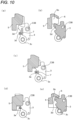
- the restriction of the rotation of the latch release lever 3 by the restriction wall 7 continues even at an intermediate position between the initial corresponding position and the pop-up corresponding position of the push portion forming member 5 as shown in Fig. 10(c) , and is eliminated when the push portion forming member 5 reaches the pop-up corresponding position as shown in Fig. 10(d) . Thereafter, the latch release lever 3 can be rotated by pushing the pushed portion 3d by the lever push portion 6 of the push portion forming member 5.
- an inertia stopper 14 for restricting the movement of the push portion forming member 5 when a collision load is applied to the vehicle is incorporated in the handle device.
- the inertia stopper 14 is rotatably connected to the handle base 8, rotates between a standby rotation position shown in Fig. 11(a) and a stop position shown in Fig. 11(b) , and is biased toward the standby rotation position by a torsion spring (not shown) wound around the rotation center C148.
- the inertia stopper 14 is formed as a cylindrical body whose gravity center position is set so as to move from the standby rotation position to the stop position by inertia when a collision force due to a collision is applied. As shown in Fig. 11(a) , since a movement path (clockwise rotation around the rotation center C108 in Fig. 11(a) ) of the stopper piece 5a of the push portion forming member 5 is opened at the standby rotation position, the rotation following an rotation operation of the operation link 10 to the latch operation corresponding position is allowed.
- the inertia stopper 14 rotates from the standby rotation position to the stop position.
- the inertia stopper 14 blocks the movement path of the stopper piece 5a of the push portion forming member 5, and thus the push portion forming member 5 stays at an interference position with the inertia stopper 14 without following the rotation of the operating link 10. Therefore, it is possible to reliably prevent the latch release lever 3 from operating and the door from being opened unnecessarily.
Landscapes
- Engineering & Computer Science (AREA)
- Mechanical Engineering (AREA)
- Lock And Its Accessories (AREA)
Description
- The present invention relates to a handle device for a vehicle.
-
Patent Literature 1 discloses a handle device having a flash surface specification, which is accommodated in a recess formed in a vehicle door or the like when not in use and is moved to a projecting position by an electric actuator when in use. - The handle device of
Patent Literature 1 includes an outer handle (handle body) that is rotatable about a rotation axis, a handle lever that is rotatable about a predetermined rotation axis and includes a link hole into which a linking protrusion formed in the handle body is fitted, and a drive lever that is rotationally driven by an electric motor. - When the electric motor is driven when the handle body is held at an initial portion when not in use, the drive lever rotates, and an abutment pin is pushed against a pin provided on the drive lever to rotate the handle lever, whereby the handle body moves from the initial position to a pop-up position.
- When the handle body is further rotated from the pop-up position, a pressure receiving portion is pushed by a latch mechanism side arm portion provided in the drive lever in accordance with rotation of the drive lever, whereby a latch release lever is rotated, and a latch mechanism connected to the latch release lever is unlocked.
- An inertia lever is rotatably connected to a support case to which the handle body is attached. When an impact due to a collision is applied, the inertia lever rotates to a restriction position and restricts an operation of the handle body at the initial position to prevent an inadvertent release operation of a door lock and an accompanying opening operation of a door.
-
- Patent Literature 1:
JP 2015-090028A - Patent Literature 2:
US 2013/121008 A1 - Patent Literature 3:
US 2013/241215 A1 - In the handle device of
Patent Literature 1, the latch release lever is pushed by the handle lever to operate, and can rotate independently from the handle lever toward a latch unlocking operation direction. Therefore, in a case where an impact due to a collision is applied, for example, even if the handle lever is provided with movement restriction means against a collision impact force and thus the handle lever is not operated, only the latch release lever may rotate due to an inertia force to release the door lock, so the reliability against collision is low.Patent Literature 2 discloses a rip device for a closure device for a movable part, such as a door, lid or the like, of a vehicle, comprising a grip part, which is movably mounted relative to the movable part, wherein the closure device can be connected to the grip part via a connecting element and the grip part is used to actuate the closure device.Patent Literature 3 discloses a retractable handle arrangement that comprises a handle movable between stowed, deployed and operative states, wherein movement is controlled by a mechanism having first and second links each connected to a supporting structure and to the handle. - According to the embodiment of the present invention, in the handle device for a vehicle, it is possible to prevent an inadvertent door lock releasing operation due to an independent operation of the latch release lever alone in the event of an impact being applied due to a collision.
- According to the embodiment of the present invention, a handle device for a vehicle includes a
handle body 2, alatch release lever 3, a door latch device in adoor 4, anelectric actuator 1, and a pushportion forming member 5. Thehandle body 2 is configured to be driven from an initial position to a pop-up position by theelectric actuator 1 and is manually operated to a latch operation position beyond the pop-up position, and the handle device is configured such that a latch of thedoor latch device 4 is released by thelatch release lever 3 being rotationally driven to a latch release position. The pushportion forming member 5 is configured to move from an initial corresponding position to a latch operation corresponding position in accordance with an operation of thehandle body 2, the initial corresponding position corresponding to the initial position of thehandle body 2 and the latch operation corresponding position corresponding to the latch operation position of thehandle body 2. The pushportion forming member 5 has alever push portion 6 configured to, at the latch operation corresponding position, push thelatch release lever 3 and rotate thelatch release lever 3 to the latch release position. The pushportion forming member 5 has arestriction wall 7. Therestriction wall 7 prevents the latch release lever 3 from rotating toward the latch release position within a region from the initial corresponding position to a pop-up corresponding position corresponding to the pop-up position of thehandle body 2. - In the present invention, when the
handle body 2 having been driven to the pop-up position by theelectric actuator 1 is further operated to the latch operation position, the pushportion forming member 5 operating in accordance with the operation of thehandle body 2 moves from the initial corresponding position corresponding to the initial position of thehandle body 2 to the latch operation corresponding position via the pop-up corresponding position corresponding to the pop-up position. With movement of the pushportion forming member 5, thelever push portion 6 formed in the pushportion forming member 5 pushes thelatch release lever 3 to rotate thelatch release lever 3 to the latch release position, thereby operating thedoor latch device 4. - When an impact force due to a collision such as a side collision is applied to the handle device, it is not possible to prevent the
latch release lever 3 from operating independently toward a direction of the latch release position due to an inertia force even if the pushportion forming member 5 is provided with appropriate movement restriction means for the time of a collision impact to restrict an operation by the inertial force, the latch release lever 3 operating in response to a push operation from thelever push portion 6 and being not directly connected to the pushportion forming member 5. - In the present invention in which the
restriction wall 7 is provided in the pushportion forming member 5 to restrict the independent operation of thelatch release lever 3, thelatch release lever 3 does not operate alone due to an impact load to an extent that the pushportion forming member 5 does not operate, or due to a bound by the impact load, and thus it is possible to prevent inadvertent door opening. - The push
portion forming member 5 may be formed integrally with thehandle body 2 as long as the pushportion forming member 5 is movable from the initial corresponding position to the latch operation corresponding position in accordance with the operation of thehandle body 2, or may be formed as a link member having one end thereof rotatably connected to thehandle body 2. - The handle device for a vehicle may further include a
handle base 8, adrive arm 9, and anoperation link 10. The drive arm is configured such that one end of thedrive arm 9 may be rotatably connected to one end of thehandle body 2, the other end of thedrive arm 9 may be rotatably connected to thehandle base 8, and thedrive arm 9 may be driven by theelectric actuator 1. Theoperation link 10 may form a link mechanism together with thehandle body 2, thedrive arm 9, and thehandle base 8. One end of theoperation link 10 may be rotatably connected to the other end of thehandle body 2, and the other end of theoperation link 10 may be rotatably connected to thehandle base 8. Theoperation link 10 may include the pushportion forming member 5. - In this aspect, when the
drive arm 9 is rotationally driven by theelectric actuator 1 such as a motor, thehandle body 2, which is connected to theoperation link 10 at one end and to thedrive arm 9 at the other end and forms the link mechanism as a whole, moves from the initial position to the pop-up position. Thereafter, when thehandle body 2 is further operated and moved to the latch operation position, the pushportion forming member 5 provided in theoperation link 10 and thelatch release lever 3 are driven to operate thedoor latch device 4. - The link mechanism can be configured as a four-joint link mechanism by the
handle base 8, thedrive arm 9, theoperation link 10, and thehandle body 2, and in this case, a latch release operation of thedoor latch device 4 can be performed by manually pulling out thehandle body 2 having been driven to the pop-up position by theelectric actuator 1 further to the latch operation position. - When the four-joint link mechanism is configured as a parallel link mechanism, the
handle body 2 moves in parallel from the initial position, and thus usability is improved. - In the handle device for a vehicle, a connection portion between the
operation link 10 and thehandle body 2 may have a sliding pair. Thehandle body 2 may be configured to move from the pop-up position to the latch operation position by a rotation operation of thehandle body 2 about a rotation center of thehandle body 2 and thedrive arm 9. - In the handle device for a vehicle, the
lever push portion 6 may be in a non-contact state with thelatch release lever 3 from the initial corresponding position to the pop-up corresponding position. Since a non-contact region set between thelever push portion 6 and thelatch release lever 3 can absorb an unauthorized operation due to error accumulation or the like of thelever push portion 6, operation reliability can be improved. - The handle device for a vehicle may further include an inertia stopper. The inertia stopper may be configured to, when a collision impact load is applied, rotate to a stop position and prevent the push
portion forming member 5 from moving toward the latch operation corresponding position. It is possible to reliably prevent unauthorized door opening due to the collision impact load. - According to the embodiment of the present invention, it is possible to prevent an inadvertent door lock releasing operation due to an independent operation of the latch release lever alone in the event of an impact due to a collision.
-
- [
Fig. 1] Fig. 1 is a front view of a handle device. - [
Fig. 2] Fig. 2 is a rear view of the handle device. - [
Fig. 3] Fig. 3 is a cross-sectional view taken along aline 3A-3A ofFig. 1 . - [
Figs. 4] Fig. 4(a) shows power transmission of an electric actuator in a drive source of a drive arm.Fig. 4(b) shows a cam in the drive source of the drive arm.Fig. 4(c) shows a diagram of the cam in the drive source of the drive arm. - [
Figs. 5] Fig. 5(a) shows a state in which the drive arm is at an initial corresponding position in an operation of the cam.Fig. 5(b) shows a state between the initial corresponding position and a pop-up corresponding position in the operation of the cam.Fig. 5(c) shows the pop-up corresponding position in the operation of the cam. - [
Figs. 6] Fig. 6(a) shows a pop-up position of a handle body in an operation of a handle.Fig. 6(b) shows a latch operation position in the operation of the handle. - [
Figs. 7] Fig. 7(a) is an enlarged view of a main part ofFig. 2 in a latch release lever.Fig. 7(b) is a view taken in a direction of anarrow 7B inFig. 7(a). Fig. 7(c) is a view of the latch release lever as viewed from a direction of anarrow 7C inFig. 7(b) . - [
Figs. 8] Fig. 8(a) is a view taken in a direction of anarrow 8A inFig. 8(b). Fig. 8(b) is a perspective view. - [
Figs. 9] Fig. 9(a) is a view taken in a direction of anarrow 9A inFig. 9(d) showing a push portion forming member.Fig. 9(b) is a cross-sectional view taken along aline 9B-9B ofFig. 9(a). Fig. 9(c) is a cross-sectional view taken along aline 9C-9C ofFig. 9(a). Fig. 9(d) is a perspective view of the push portion forming member. - [
Figs. 10] Fig. 10(a) is a cross-sectional view taken along aline 10A-10A ofFig. 7(b) .Fig. 10(b) is a cross-sectional view taken along aline 10B-10B ofFig. 7(b) .Fig. 10(c) is a view corresponding toFig. 10(a) when an operation link is at an intermediate position between the initial corresponding position and the pop-up corresponding position.Fig. 10(d) is a view corresponding toFig. 10(a) when the operation link is at the pop-up correspondence position.Fig. 10(e) is a view corresponding toFig. 10(b) when the operation link is at the pop-up correspondence position. - [
Figs. 11] Fig. 11(a) shows a non-operating state in an operation of an inertia stopper.Fig. 11(b) shows a state in which the inertia stopper is rotated to a stopper rotated position by an impact load in the operation of the inertia stopper. - A door handle device includes a
handle base 8, ahandle body 2, adrive arm 9 connecting thehandle body 2 to thehandle base 8, and anoperation link 10, and is to be fixed to a door of a vehicle at thehandle base 8. - With the
handle base 8 fixed to the door, thehandle body 2 can be moved from an initial position shown inFigs. 1 and3 to a pop-up position shown inFig. 6(a) and further to a latch operation position at which one end of thehandle body 2 is pulled up from the pop-up position as shown inFig. 6(b) . - The door handle device has a flush surface specification in which the
handle body 2 is accommodated in the door and a surface of thehandle body 2 is substantially in the same plane as a door surface when not in use. The initial position of thehandle body 2 corresponds to a non-use posture. Thehandle base 8 is formed with a handleaccommodating recess 8a to accommodate thehandle body 2 when thehandle body 2 is at the initial position (seeFig. 3 ). - As shown in
Fig. 3 , thedrive arm 9 and theoperation link 10 are connected to thehandle base 8 so as to be rotatable about rotation centers C98 and C108. The rotation centers C98 and C108 of thedrive arm 9 and theoperation link 10 with respect to thehandle base 8 are appropriately spaced apart from each other in a front-rear direction, that is, in a longitudinal direction of thehandle base 8, and the rotation center C98 of thedrive arm 9 is disposed in front of the rotation center C108 of theoperation link 10. - In this description, a left side of
Fig. 1 is referred to as "front", a right side is referred to as "rear", a direction directed out of the page ofFig. 1 is referred to as a "front surface" direction, and an opposite direction thereof is referred to a "back surface" direction. - An
electric actuator 1 such as a motor is to be fixed to thehandle base 8, and as shown inFig. 4(a) , power of themotor 1 is transmitted to acam 11 rotatably connected to thehandle base 8 via a worm 1a, a worm wheel 1b, and a reduction gear 1c. - A pressed
portion 9a is formed on thedrive arm 9 so as to correspond to thecam 11 to be rotationally driven around a rotation center C11 and is pushed by thecam 11, and thus thedrive arm 9 rotates about the rotation center C98 from an initial corresponding position corresponding to the initial position of thehandle body 2 to a pop-up corresponding position corresponding to the pop-up position of thehandle body 2 in accordance with rotation of thecam 11. - In order to ensure the contact of the pressed
portion 9a with thecam 11, atorsion spring 9b is mounted around a connection portion C98 between thehandle base 8 and thedrive arm 9 to bias thedrive arm 9 counterclockwise inFig. 3 . - As shown in
Fig. 4(b) , thecam 11 comes into contact with the pressedportion 9a at a start point P1 when thehandle body 2 is at the initial position, and rotates counterclockwise by an angle θ about the rotation center C11 inFig. 4(b) while maintaining the contact with the pressedportion 9a. When thecam 11 comes into contact with the pressedportion 9a at an end point P2, thehandle body 2 moves to the pop-up position. -
Figs. 5(a) to 5(c) are explanatory views showing a state in which thedrive arm 9 is operated by thecam 11.Fig. 5(a) shows a state in which thedrive arm 9 is at the initial corresponding position,Fig. 5(c) shows a state in which thedrive arm 9 is at the pop-up corresponding position, andFig. 5(b) shows a state in which thedrive arm 9 is on the way from the initial corresponding position to the pop-up corresponding position. A reference numeral H shown inFigs. 5(b) and 5(c) denotes a movement amount of a connection point C29 of thedrive arm 9 with thehandle body 2.Fig. 4(c) is a cam diagram of thecam 11 for obtaining the movement amount. A horizontal axis represents a rotation angle θ of thecam 11, and a vertical axis represents the movement amount H in a height direction of the connection point C29 with thehandle body 2. - As shown in
Fig. 4(c) , thecam 11 is configured such that an increment in a movement distance of the connection point C29 of thedrive arm 9 with thehandle body 2 in a height direction per unit angle is small in an initial stage of rotation and gradually increases as thecam 11 approaches the end point. Immediately after starting to be driven by themotor 1, thecam 11 slowly ascends in a vertical direction, and is driven so as to gradually increase an ascending speed as thehandle body 2 approaches the pop-up position. - As a result, a driving force is maximized at an initial stage of driving when the ascending speed is low, that is, when the
handle body 2 starts to move from the initial position. By virtue of this configuration, for example, even when thin ice is formed around thehandle body 2, it is possible to expect a sufficient driving force for crushing the ice and prevent an operation failure due to freezing. - When the handle body returns from the pop-up position to the initial position, since a descending speed decreases in a vicinity of the initial position, it is possible to prevent a collision with the
handle base 8, packing, or the like, and it is possible to prevent an occurrence of collision noise, rebound, or the like. - Further, as shown in
Fig. 5(c) , when thedrive arm 9 is at the pop-up corresponding position, the rotation center C11 of thecam 11 is disposed in a vicinity of a normal line N drawn down from a contact point with the pressedportion 9a. Therefore, a horizontal component when a force is applied from the pressedportion 9a to the contact point P2 of thecam 11, that is, a force to rotate thecam 11, is small. - Therefore, even if a load toward the initial position, that is, a force for pushing the
handle body 2 is applied to thehandle body 2 when thehandle body 2 is at the pop-up corresponding position, only a force directed toward the rotation center is generally applied to thecam 11, and a force in a direction perpendicular to the force is small. Therefore, a rotational operation force applied to thecam 11 is small, and a force applied to a worm from a worm wheel can be small. - As shown in
Figs. 3 ,6(a), and 6(b) , thehandle body 2 is provided withlink connection portions 2a protruding toward a back-surface side and provided at both front and rear end portions of the handle body, and ahandhold recess 2b serving as a handhold when thehandle body 2 is operated is formed between the front and rearlink connection portions 2a. - The other end of the
drive arm 9, which is connected to thehandle base 8 at one end, is rotatably connected to the frontlink connection portion 2a of thehandle body 2, and the other end of theoperation link 10 is connected to the rearlink connection portion 2a. - The connection between the
operation link 10 and thehandle body 2 is rotatable and slidable. In this example, aconnection pin 12 that is fixed to the rearlink connection portion 2a and provides a rotation center C210 is inserted into along hole 10a formed in an end portion of theoperation link 10, and thus the rotation center C210, that is, theconnection pin 12 is slidable. Theconnection pin 12 is inserted into thelong hole 10a and then retained by retaining means as appropriate. - As shown in
Fig. 3 , the rotation center C98 of thedrive arm 9 with thehandle base 8, the rotation center C29 of thedrive arm 9 and thehandle body 2, theconnection pin 12 of thehandle body 2, and the rotation center C108 of theoperation link 10 with respect to thehandle base 8 are disposed at vertex positions of a parallelogram. Thelong hole 10a has one end position (initial end position) that is a position of theconnection pin 12 at the vertex position of the parallelogram, and extends in a rearward and slightly back surface direction, that is, in a direction in which a link length of theoperation link 10 is extended by sliding of theconnection pin 12. - As shown in
Fig. 3 , theoperation link 10 is biased toward the initial corresponding position corresponding to the initial position of thehandle body 2 by atorsion spring 10b wound around the rotation center 108 of theoperation link 10 with thehandle base 8, thetorsion spring 9b that biases thedrive arm 9 toward the initial corresponding position corresponding to the initial position of thehandle body 2 is wound around the rotation center C98 of thedrive arm 9 with respect to thehandle base 8 as described above, and thetorsion spring 10b biases theconnection pin 12 toward the initial end position in thelong hole 10a, that is, toward the vertex position of the parallelogram and holds theconnection pin 12 at the position. - Therefore, in this example, when the
electric actuator 1 is driven to rotate thecam 11 counterclockwise inFig. 3 when thehandle body 2 is at the initial position shown inFig. 3 , thedrive arm 9 rotates clockwise about the rotation center. - As described above, since the
operation link 10 and thehandle body 2 are held, by actions of the torsion springs 10b and 9b, at the initial corresponding position where theconnection pin 12 minimizes the link length of theoperation link 10b, thedrive arm 9, theoperation link 10, thehandle body 2, and thehandle base 8 form a parallel crank mechanism having thehandle base 8 as a fixed link, and thehandle body 2 moves from the initial position to the pop-up position shown inFig. 6(a) by the rotation of thedrive arm 9 while holding a parallel posture. - When the
handle body 2 reaches the pop-up position, the drive of theelectric actuator 1 is stopped by a switch (not shown), and thehandle body 2 is held at the pop-up position. When theelectric actuator 1 is reversely driven from this state, thedrive arm 9 returns to the initial corresponding position by the torsion spring wound around the rotation center and thehandle body 2 returns to the initial position. - At the pop-up position, the
handle body 2 is held in a posture parallel to the door surface. Thereafter, by pulling out a rear end side of thehandle body 2 to an outside of the door, thehandle body 2 is rotated about the rotation center with thedrive arm 9 until thehandle body 2 comes into contact with a stopper (not shown), and as shown inFig. 6(b) , thehandle body 2 can be moved to a latch release position inclined from the front-end portion toward the rear end portion. - The rotation of the
handle body 2 from the pop-up position to the latch release position is performed by a manual rotation operation, and in accordance with the rotation operation of thehandle body 2 to the latch release position, theoperation link 10 further rotates beyond the pop-up corresponding position corresponding to the pop-up position of thehandle body 2 and rotates to a latch operation corresponding position. - In this example, an operation of the
door latch device 4 is performed by operating thelatch release lever 3 by the pushportion forming member 5 fixed to theoperation link 10. - As shown in
Figs. 7(a) and 7(b) , the pushportion forming member 5 is fixed on the rotation center C108 of theoperation link 10 with thehandle base 8, and rotates around the rotation center C108 in accordance with the rotation of theoperation link 10. - The
latch release lever 3 is rotatably connected to thehandle base 8 around a rotation center C38 perpendicular to the rotation center C108 of theoperation link 10 with respect to thehandle base 8. As shown inFigs. 8(a) and 8(b) , thelatch release lever 3 includes a plate-like body portion 3a, acylindrical portion 3b through which a rotation shaft is inserted, thecylindrical portion 3b protruding from a plate-like body portion 3a, and acable connecting portion 3c for holding a tip of an inner cable (not shown) of acable device 13, thecable connecting portion 3c being formed in a vicinity of thecylindrical portion 3b. - The
latch release lever 3 is biased clockwise inFig. 7(c) by a torsion spring (not shown) wound around the rotation center C38, and is held at an initial position shown inFig. 7(c) . - Further, the
latch release lever 3 includes a pushedportion 3d. As will be described later, the pushedportion 3d is pushed by thelever push portion 6 of the pushportion forming member 5, whereby thelatch release lever 3 rotates counterclockwise inFig. 7(c) to apply a pulling operation force to thecable device 13 and operate the door latch device 4 (seeFig. 2 ). - As shown in
Figs. 9(a) to 9(d) , the pushportion forming member 5 includes astopper piece 5a at one end portion and arecess 5b configured to receive the plate-like body portion 3a of thelatch release lever 3 at the other end portion, and thelever push portion 6 is formed on a peripheral wall portion of therecess 5b. - The push
portion forming member 5 moves from a state shown inFig. 10(b) to a state shown inFig. 10(e) in accordance with the rotation of theoperation link 10 to the pop-up corresponding position, and thelever push portion 6 comes into contact with the pushedportion 3d of thelatch release lever 3. Thereafter, when thehandle body 2 is operated to the latch operation position and theoperation link 10 is rotated to an operation corresponding position, thelever push portion 6 of the pushportion forming member 5 pushes the pushedportion 3d of thelatch release lever 3, and thelatch release lever 3 rotates around the rotation center C38 to operate thedoor latch device 4. - Further, a
weight portion 5c is formed in a vicinity of thelever push portion 6 of the pushportion forming member 5 to adjust the moment of inertia of the pushportion forming member 5. A value of the moment of inertia is set to such a magnitude that, when an impact force due to a collision is applied to the vehicle, an inertia force generated in the pushportion forming member 5 by inertia and directed toward a direction to operate thelatch release lever 3 will be canceled by inertia and the rotation in the direction will not be generated. A weight of theweight portion 5c, an arm length from the rotation center C108, and the like are determined based on the moment of inertia required for the pushportion forming member 5. - Therefore, in this example, even when a collision impact force is applied, an operation force generated in the push
portion forming member 5 is canceled by the moment of inertia of the pushportion forming member 5, and thus, thelatch release lever 3 is not pushed and inadvertent door opening is prevented. - Further, the push
portion forming member 5 is provided with arestriction wall 7, and thelatch release lever 3 is provided with arestriction protrusion 3e. - As shown in
Figs. 8(a) and 8(b) , therestriction protrusion 3e is erected from the plate-like body portion 3a, and therestriction wall 7 is formed as a wall surface of therecess 5b as shown inFig. 9(c) . - As shown in
Fig. 10(a) , when the pushportion forming member 5 is at the initial corresponding position, the rotation of thelatch release lever 3 in a direction toward the latch release position, that is, counterclockwise rotation inFig. 10(a) is impossible because therestriction wall 7 blocks a movement path of therestriction protrusion 3e, and it is possible to prevent thelatch release lever 3 from moving independently to the latch release position due to an impact force such as a collision and from operating thedoor latch device 4. - The restriction of the rotation of the
latch release lever 3 by therestriction wall 7 continues even at an intermediate position between the initial corresponding position and the pop-up corresponding position of the pushportion forming member 5 as shown inFig. 10(c) , and is eliminated when the pushportion forming member 5 reaches the pop-up corresponding position as shown inFig. 10(d) . Thereafter, thelatch release lever 3 can be rotated by pushing the pushedportion 3d by thelever push portion 6 of the pushportion forming member 5. - Further, an
inertia stopper 14 for restricting the movement of the pushportion forming member 5 when a collision load is applied to the vehicle is incorporated in the handle device. Theinertia stopper 14 is rotatably connected to thehandle base 8, rotates between a standby rotation position shown inFig. 11(a) and a stop position shown inFig. 11(b) , and is biased toward the standby rotation position by a torsion spring (not shown) wound around the rotation center C148. - The
inertia stopper 14 is formed as a cylindrical body whose gravity center position is set so as to move from the standby rotation position to the stop position by inertia when a collision force due to a collision is applied. As shown inFig. 11(a) , since a movement path (clockwise rotation around the rotation center C108 inFig. 11(a) ) of thestopper piece 5a of the pushportion forming member 5 is opened at the standby rotation position, the rotation following an rotation operation of theoperation link 10 to the latch operation corresponding position is allowed. - On the other hand, when a collision force from a side of the vehicle is applied to the vehicle, the
inertia stopper 14 rotates from the standby rotation position to the stop position. As shown inFig. 11(b) , when theinertia stopper 14 is at the stop position, theinertia stopper 14 blocks the movement path of thestopper piece 5a of the pushportion forming member 5, and thus the pushportion forming member 5 stays at an interference position with theinertia stopper 14 without following the rotation of theoperating link 10. Therefore, it is possible to reliably prevent thelatch release lever 3 from operating and the door from being opened unnecessarily. -
- 1: electric actuator
- 2: handle body
- 3: latch release lever
- 4: door latch device
- 5: push portion forming member
- 6: lever push portion
- 7: restriction wall
- 8: handle base
- 9: drive arm
- 10: operation link
Claims (5)
- A handle device for a vehicle, comprising:a handle body;a latch release lever (3);a door latch device (4) in a door;an electric actuator (1); anda push portion forming member (5),wherein the handle body (2) is configured to be driven from an initial position to a pop-up position by the electric actuator (1) and is manually operated to a latch operation position beyond the pop-up position, and the handle device is configured such that a latch of the door latch device (4) is released by the latch release lever (3) being rotationally driven to a latch release position,wherein the push portion forming member (5) is configured to move from an initial corresponding position to a latch operation corresponding position in accordance with an operation of the handle body (2), the initial corresponding position corresponding to the initial position of the handle body (2) and the latch operation corresponding position corresponding to the latch operation position of the handle body (2),wherein the push portion forming member (5) has a lever push portion (6) configured to, at the latch operation corresponding position, push the latch release lever (3) and rotate the latch release lever (3) to the latch release position, characterized in thatthe push portion forming member (5) has a restriction wall (7), andwherein the restriction wall (7) prevents the latch release lever (3) from rotating toward the latch release position within a region from the initial corresponding position to a pop-up corresponding position corresponding to the pop-up position of the handle body (2).
- The handle device for a vehicle according to claim 1, further comprising:a handle base (8);a drive arm (9); andan operation link (10),wherein the drive arm (9) is configured such that one end of the drive arm (9) is rotatably connected to one end of the handle body (2), the other end of the drive arm is rotatably connected to the handle base (8), and the drive arm (9) is driven by the electric actuator (1),wherein the operation link (10) forms a link mechanism together with the handle body (2), the drive arm (9), and the handle base (8),wherein one end of the operation link (10) is rotatably connected to the other end of the handle body (2), and the other end of the operation link (10) is rotatably connected to the handle base (8), andwherein the operation link (10) includes the push portion forming member (5).
- The handle device for a vehicle according to claim 2,wherein a connection portion between the operation link (10) and the handle body (2) has a sliding pair, andwherein the handle body (2) is configured to move from the pop-up position to the latch operation position by a rotation operation of the handle body (2) about a rotation center of the handle body (2) and the drive arm (9).
- The handle device for a vehicle according to any one of claims 1 to 3,
wherein the lever push portion (6) is in a non-contact state with the latch release lever (3) from the initial corresponding position to the pop-up corresponding position. - The handle device for a vehicle according to any one of claims 1 to 4, further comprising:an inertia stopper (14),wherein the inertia stopper (14) is configured to, when a collision impact load is applied, rotate to a stop position and prevent the push portion forming member (5) from moving toward the latch operation corresponding position.
Applications Claiming Priority (2)
| Application Number | Priority Date | Filing Date | Title |
|---|---|---|---|
| JP2019165089A JP7313996B2 (en) | 2019-09-11 | 2019-09-11 | vehicle steering wheel |
| PCT/JP2020/030014 WO2021049213A1 (en) | 2019-09-11 | 2020-08-05 | Handle device for vehicle |
Publications (3)
| Publication Number | Publication Date |
|---|---|
| EP4030022A1 EP4030022A1 (en) | 2022-07-20 |
| EP4030022A4 EP4030022A4 (en) | 2023-09-27 |
| EP4030022B1 true EP4030022B1 (en) | 2025-05-21 |
Family
ID=74863821
Family Applications (1)
| Application Number | Title | Priority Date | Filing Date |
|---|---|---|---|
| EP20862967.5A Active EP4030022B1 (en) | 2019-09-11 | 2020-08-05 | Handle device for vehicle |
Country Status (5)
| Country | Link |
|---|---|
| US (1) | US11926196B2 (en) |
| EP (1) | EP4030022B1 (en) |
| JP (1) | JP7313996B2 (en) |
| CN (1) | CN114375359A (en) |
| WO (1) | WO2021049213A1 (en) |
Families Citing this family (8)
| Publication number | Priority date | Publication date | Assignee | Title |
|---|---|---|---|---|
| JP6957390B2 (en) * | 2018-03-09 | 2021-11-02 | 株式会社アルファ | Vehicle door handle device |
| KR20220170648A (en) * | 2021-06-23 | 2022-12-30 | 현대자동차주식회사 | System and method for controlling vehicle |
| EP4261374A1 (en) * | 2022-04-13 | 2023-10-18 | U-Shin Italia S.p.A. | Vehicle door handle assembly |
| EP4261371B1 (en) * | 2022-04-13 | 2024-09-04 | Minebea AccessSolutions Italia S.p.A. | Handle arrangement |
| EP4273358B1 (en) * | 2022-05-03 | 2025-11-19 | Minebea AccessSolutions Italia S.p.A. | Handle arrangement with flap system |
| JP7818149B2 (en) * | 2022-06-21 | 2026-02-20 | サカエ理研工業株式会社 | Door handle device for vehicle |
| EP4442944A1 (en) * | 2023-04-05 | 2024-10-09 | Minebea AccessSolutions Italia S.p.A. | Vehicle door handle assembly |
| CN117166859A (en) * | 2023-08-23 | 2023-12-05 | 宁波帅特龙集团有限公司 | A hidden car door outer handle |
Family Cites Families (21)
| Publication number | Priority date | Publication date | Assignee | Title |
|---|---|---|---|---|
| JP3200695B2 (en) * | 1992-03-16 | 2001-08-20 | 株式会社パイオラックス | Car storage device with safety function |
| DE69310790T2 (en) | 1992-03-16 | 1998-01-02 | Kato Hatsujo Kaisha Ltd | Safety lock for a vehicle storage compartment |
| US8786401B2 (en) * | 2009-12-23 | 2014-07-22 | Magna Mirrors Of America, Inc. | Extendable flush door handle for vehicle |
| GB2477085B (en) * | 2010-01-15 | 2014-08-20 | Jaguar Land Rover Ltd | Retractable handle for a door or the like |
| DE102010016869A1 (en) * | 2010-05-10 | 2011-11-10 | Huf Hülsbeck & Fürst Gmbh & Co. Kg | Handle device, in particular for a vehicle |
| JP6084551B2 (en) | 2013-11-06 | 2017-02-22 | 株式会社ホンダロック | Outdoor handle device for vehicle door |
| DE102013112706A1 (en) | 2013-11-18 | 2015-05-21 | Illinois Tool Works Inc. | System comprising a door handle and an actuating device for the door handle |
| US10767397B2 (en) * | 2015-02-25 | 2020-09-08 | Magna Closures S.P.A. | Single motor latch assembly with power cinch and power release having soft opening function |
| KR101875658B1 (en) * | 2016-08-24 | 2018-07-06 | 현대자동차 주식회사 | Retractable outside door handle assembly for vehicle |
| FR3060630B1 (en) * | 2016-12-20 | 2019-11-22 | Akwel | AFFLEURANT OPENING CONTROL WITH EJECTION AND MECHANICAL OR ELECTRICAL RETRACTION. |
| DE102017101415A1 (en) * | 2017-01-25 | 2018-07-26 | Daimler Ag | Door handle assembly for a vehicle door |
| DE102017101418B4 (en) * | 2017-01-25 | 2025-05-28 | Huf Hülsbeck & Fürst Gmbh & Co. Kg | Door handle arrangement for a vehicle door |
| DE102017109113A1 (en) * | 2017-04-27 | 2018-10-31 | Huf Hülsbeck & Fürst Gmbh & Co. Kg | Vehicle door handle |
| EP3404177B1 (en) | 2017-05-16 | 2019-11-27 | U-Shin Italia S.p.A. | Flush handle control mechanism |
| ES2928686T3 (en) * | 2017-05-16 | 2022-11-21 | U Shin Italia Spa | Unlocking device for a door lock |
| EP3447218B1 (en) * | 2017-08-23 | 2020-06-03 | U-Shin Italia S.p.A. | Locking system provided with a handle and an offset inertial system |
| DE102017010196B3 (en) * | 2017-10-30 | 2019-04-25 | Daimler Ag | Handle device for a motor vehicle door |
| JP2019165089A (en) | 2018-03-19 | 2019-09-26 | 東芝メモリ株式会社 | Semiconductor device |
| US11536058B2 (en) * | 2018-08-31 | 2022-12-27 | Hyundai Motor Company | Structure for connecting door latch cable to retractable outside door handle assembly for vehicle |
| US11680432B2 (en) * | 2018-10-02 | 2023-06-20 | Magna Mirrors Of America, Inc. | Flush door handle for vehicle |
| KR102144784B1 (en) * | 2019-01-22 | 2020-08-18 | 주식회사 우보테크 | Flush Handle For Vehicle Door |
-
2019
- 2019-09-11 JP JP2019165089A patent/JP7313996B2/en active Active
-
2020
- 2020-08-05 CN CN202080063816.2A patent/CN114375359A/en active Pending
- 2020-08-05 WO PCT/JP2020/030014 patent/WO2021049213A1/en not_active Ceased
- 2020-08-05 EP EP20862967.5A patent/EP4030022B1/en active Active
-
2022
- 2022-03-10 US US17/691,822 patent/US11926196B2/en active Active
Also Published As
| Publication number | Publication date |
|---|---|
| US11926196B2 (en) | 2024-03-12 |
| US20220194188A1 (en) | 2022-06-23 |
| CN114375359A (en) | 2022-04-19 |
| WO2021049213A1 (en) | 2021-03-18 |
| JP2021042575A (en) | 2021-03-18 |
| JP7313996B2 (en) | 2023-07-25 |
| EP4030022A1 (en) | 2022-07-20 |
| EP4030022A4 (en) | 2023-09-27 |
Similar Documents
| Publication | Publication Date | Title |
|---|---|---|
| EP4030022B1 (en) | Handle device for vehicle | |
| EP4030023B1 (en) | Handle device for vehicle | |
| CN108222713B (en) | Leveling opening control device | |
| KR101637820B1 (en) | Retractable handle system for vehicle | |
| US9631404B2 (en) | Vehicle door lock apparatus | |
| EP2795022B1 (en) | Safety device for vehicle door handle | |
| US10174528B2 (en) | Motor vehicle door handle | |
| KR101801399B1 (en) | Handle for a door leaf of an automobile | |
| WO2019172057A1 (en) | Door handle device for vehicles | |
| EP4030025A1 (en) | Vehicular handle device | |
| EP3922790B1 (en) | Vehicle door handle device | |
| KR20180071313A (en) | Car Door Handle | |
| CN106168089A (en) | Latch with dual actuation and method of construction thereof | |
| KR101946915B1 (en) | Assembly of Flush Door Dandle for Vehicle | |
| US11519204B2 (en) | Opening control with a linear actuator for a motor vehicle | |
| US12006742B2 (en) | Door handle device for vehicle | |
| KR20050047984A (en) | Apparatus for prevention from opening of door | |
| KR102663985B1 (en) | Retractable outside door handle assembly for vehicle | |
| JP7265664B2 (en) | vehicle door handle device | |
| JP4598668B2 (en) | Vehicle door lock device | |
| KR20200025511A (en) | Inertia Linkage and Retractable outside door handle assembly for vehicle using the same | |
| KR101187886B1 (en) | Opening and closing apparatus for special vehicles | |
| JP5582845B2 (en) | Vehicle door handle device | |
| JP4523857B2 (en) | Back door locking device | |
| CN119773463A (en) | Door support device |
Legal Events
| Date | Code | Title | Description |
|---|---|---|---|
| STAA | Information on the status of an ep patent application or granted ep patent |
Free format text: STATUS: THE INTERNATIONAL PUBLICATION HAS BEEN MADE |
|
| PUAI | Public reference made under article 153(3) epc to a published international application that has entered the european phase |
Free format text: ORIGINAL CODE: 0009012 |
|
| STAA | Information on the status of an ep patent application or granted ep patent |
Free format text: STATUS: REQUEST FOR EXAMINATION WAS MADE |
|
| 17P | Request for examination filed |
Effective date: 20220330 |
|
| AK | Designated contracting states |
Kind code of ref document: A1 Designated state(s): AL AT BE BG CH CY CZ DE DK EE ES FI FR GB GR HR HU IE IS IT LI LT LU LV MC MK MT NL NO PL PT RO RS SE SI SK SM TR |
|
| DAV | Request for validation of the european patent (deleted) | ||
| DAX | Request for extension of the european patent (deleted) | ||
| P01 | Opt-out of the competence of the unified patent court (upc) registered |
Effective date: 20230509 |
|
| A4 | Supplementary search report drawn up and despatched |
Effective date: 20230828 |
|
| RIC1 | Information provided on ipc code assigned before grant |
Ipc: E05B 81/42 20140101ALN20230822BHEP Ipc: E05B 85/10 20140101ALI20230822BHEP Ipc: B60J 5/04 20060101ALI20230822BHEP Ipc: E05B 85/16 20140101ALI20230822BHEP Ipc: E05B 77/06 20140101ALI20230822BHEP Ipc: E05B 77/04 20140101AFI20230822BHEP |
|
| GRAP | Despatch of communication of intention to grant a patent |
Free format text: ORIGINAL CODE: EPIDOSNIGR1 |
|
| STAA | Information on the status of an ep patent application or granted ep patent |
Free format text: STATUS: GRANT OF PATENT IS INTENDED |
|
| RIC1 | Information provided on ipc code assigned before grant |
Ipc: E05B 81/06 20140101ALN20241107BHEP Ipc: E05B 81/42 20140101ALN20241107BHEP Ipc: E05B 85/10 20140101ALI20241107BHEP Ipc: B60J 5/04 20060101ALI20241107BHEP Ipc: E05B 85/16 20140101ALI20241107BHEP Ipc: E05B 77/06 20140101ALI20241107BHEP Ipc: E05B 77/04 20140101AFI20241107BHEP |
|
| INTG | Intention to grant announced |
Effective date: 20241210 |
|
| GRAS | Grant fee paid |
Free format text: ORIGINAL CODE: EPIDOSNIGR3 |
|
| GRAA | (expected) grant |
Free format text: ORIGINAL CODE: 0009210 |
|
| STAA | Information on the status of an ep patent application or granted ep patent |
Free format text: STATUS: THE PATENT HAS BEEN GRANTED |
|
| AK | Designated contracting states |
Kind code of ref document: B1 Designated state(s): AL AT BE BG CH CY CZ DE DK EE ES FI FR GB GR HR HU IE IS IT LI LT LU LV MC MK MT NL NO PL PT RO RS SE SI SK SM TR |
|
| REG | Reference to a national code |
Ref country code: GB Ref legal event code: FG4D |
|
| REG | Reference to a national code |
Ref country code: CH Ref legal event code: EP |
|
| REG | Reference to a national code |
Ref country code: DE Ref legal event code: R096 Ref document number: 602020051801 Country of ref document: DE |
|
| REG | Reference to a national code |
Ref country code: IE Ref legal event code: FG4D |
|
| REG | Reference to a national code |
Ref country code: NL Ref legal event code: MP Effective date: 20250521 |
|
| PG25 | Lapsed in a contracting state [announced via postgrant information from national office to epo] |
Ref country code: ES Free format text: LAPSE BECAUSE OF FAILURE TO SUBMIT A TRANSLATION OF THE DESCRIPTION OR TO PAY THE FEE WITHIN THE PRESCRIBED TIME-LIMIT Effective date: 20250521 Ref country code: FI Free format text: LAPSE BECAUSE OF FAILURE TO SUBMIT A TRANSLATION OF THE DESCRIPTION OR TO PAY THE FEE WITHIN THE PRESCRIBED TIME-LIMIT Effective date: 20250521 Ref country code: PT Free format text: LAPSE BECAUSE OF FAILURE TO SUBMIT A TRANSLATION OF THE DESCRIPTION OR TO PAY THE FEE WITHIN THE PRESCRIBED TIME-LIMIT Effective date: 20250922 |
|
| PGFP | Annual fee paid to national office [announced via postgrant information from national office to epo] |
Ref country code: DE Payment date: 20250702 Year of fee payment: 6 |
|
| REG | Reference to a national code |
Ref country code: LT Ref legal event code: MG9D |
|
| PG25 | Lapsed in a contracting state [announced via postgrant information from national office to epo] |
Ref country code: NO Free format text: LAPSE BECAUSE OF FAILURE TO SUBMIT A TRANSLATION OF THE DESCRIPTION OR TO PAY THE FEE WITHIN THE PRESCRIBED TIME-LIMIT Effective date: 20250821 Ref country code: GR Free format text: LAPSE BECAUSE OF FAILURE TO SUBMIT A TRANSLATION OF THE DESCRIPTION OR TO PAY THE FEE WITHIN THE PRESCRIBED TIME-LIMIT Effective date: 20250822 |
|
| PG25 | Lapsed in a contracting state [announced via postgrant information from national office to epo] |
Ref country code: NL Free format text: LAPSE BECAUSE OF FAILURE TO SUBMIT A TRANSLATION OF THE DESCRIPTION OR TO PAY THE FEE WITHIN THE PRESCRIBED TIME-LIMIT Effective date: 20250521 Ref country code: PL Free format text: LAPSE BECAUSE OF FAILURE TO SUBMIT A TRANSLATION OF THE DESCRIPTION OR TO PAY THE FEE WITHIN THE PRESCRIBED TIME-LIMIT Effective date: 20250521 |
|
| PG25 | Lapsed in a contracting state [announced via postgrant information from national office to epo] |
Ref country code: BG Free format text: LAPSE BECAUSE OF FAILURE TO SUBMIT A TRANSLATION OF THE DESCRIPTION OR TO PAY THE FEE WITHIN THE PRESCRIBED TIME-LIMIT Effective date: 20250521 |
|
| PGFP | Annual fee paid to national office [announced via postgrant information from national office to epo] |
Ref country code: GB Payment date: 20250703 Year of fee payment: 6 |
|
| PG25 | Lapsed in a contracting state [announced via postgrant information from national office to epo] |
Ref country code: HR Free format text: LAPSE BECAUSE OF FAILURE TO SUBMIT A TRANSLATION OF THE DESCRIPTION OR TO PAY THE FEE WITHIN THE PRESCRIBED TIME-LIMIT Effective date: 20250521 |
|
| PGFP | Annual fee paid to national office [announced via postgrant information from national office to epo] |
Ref country code: FR Payment date: 20250703 Year of fee payment: 6 |
|
| PG25 | Lapsed in a contracting state [announced via postgrant information from national office to epo] |
Ref country code: RS Free format text: LAPSE BECAUSE OF FAILURE TO SUBMIT A TRANSLATION OF THE DESCRIPTION OR TO PAY THE FEE WITHIN THE PRESCRIBED TIME-LIMIT Effective date: 20250821 |
|
| PG25 | Lapsed in a contracting state [announced via postgrant information from national office to epo] |
Ref country code: IS Free format text: LAPSE BECAUSE OF FAILURE TO SUBMIT A TRANSLATION OF THE DESCRIPTION OR TO PAY THE FEE WITHIN THE PRESCRIBED TIME-LIMIT Effective date: 20250921 |
|
| PG25 | Lapsed in a contracting state [announced via postgrant information from national office to epo] |
Ref country code: LV Free format text: LAPSE BECAUSE OF FAILURE TO SUBMIT A TRANSLATION OF THE DESCRIPTION OR TO PAY THE FEE WITHIN THE PRESCRIBED TIME-LIMIT Effective date: 20250521 |
|
| REG | Reference to a national code |
Ref country code: AT Ref legal event code: MK05 Ref document number: 1796884 Country of ref document: AT Kind code of ref document: T Effective date: 20250521 |
|
| PG25 | Lapsed in a contracting state [announced via postgrant information from national office to epo] |
Ref country code: DK Free format text: LAPSE BECAUSE OF FAILURE TO SUBMIT A TRANSLATION OF THE DESCRIPTION OR TO PAY THE FEE WITHIN THE PRESCRIBED TIME-LIMIT Effective date: 20250521 Ref country code: AT Free format text: LAPSE BECAUSE OF FAILURE TO SUBMIT A TRANSLATION OF THE DESCRIPTION OR TO PAY THE FEE WITHIN THE PRESCRIBED TIME-LIMIT Effective date: 20250521 Ref country code: SM Free format text: LAPSE BECAUSE OF FAILURE TO SUBMIT A TRANSLATION OF THE DESCRIPTION OR TO PAY THE FEE WITHIN THE PRESCRIBED TIME-LIMIT Effective date: 20250521 |
|
| PG25 | Lapsed in a contracting state [announced via postgrant information from national office to epo] |
Ref country code: CZ Free format text: LAPSE BECAUSE OF FAILURE TO SUBMIT A TRANSLATION OF THE DESCRIPTION OR TO PAY THE FEE WITHIN THE PRESCRIBED TIME-LIMIT Effective date: 20250521 |
|
| PG25 | Lapsed in a contracting state [announced via postgrant information from national office to epo] |
Ref country code: EE Free format text: LAPSE BECAUSE OF FAILURE TO SUBMIT A TRANSLATION OF THE DESCRIPTION OR TO PAY THE FEE WITHIN THE PRESCRIBED TIME-LIMIT Effective date: 20250521 |
|
| PG25 | Lapsed in a contracting state [announced via postgrant information from national office to epo] |
Ref country code: RO Free format text: LAPSE BECAUSE OF FAILURE TO SUBMIT A TRANSLATION OF THE DESCRIPTION OR TO PAY THE FEE WITHIN THE PRESCRIBED TIME-LIMIT Effective date: 20250521 Ref country code: SK Free format text: LAPSE BECAUSE OF FAILURE TO SUBMIT A TRANSLATION OF THE DESCRIPTION OR TO PAY THE FEE WITHIN THE PRESCRIBED TIME-LIMIT Effective date: 20250521 |
|
| PG25 | Lapsed in a contracting state [announced via postgrant information from national office to epo] |
Ref country code: IT Free format text: LAPSE BECAUSE OF FAILURE TO SUBMIT A TRANSLATION OF THE DESCRIPTION OR TO PAY THE FEE WITHIN THE PRESCRIBED TIME-LIMIT Effective date: 20250521 |
|
| REG | Reference to a national code |
Ref country code: DE Ref legal event code: R097 Ref document number: 602020051801 Country of ref document: DE |
|
| REG | Reference to a national code |
Ref country code: CH Ref legal event code: H13 Free format text: ST27 STATUS EVENT CODE: U-0-0-H10-H13 (AS PROVIDED BY THE NATIONAL OFFICE) Effective date: 20260324 |
|
| PLBE | No opposition filed within time limit |
Free format text: ORIGINAL CODE: 0009261 |
|
| STAA | Information on the status of an ep patent application or granted ep patent |
Free format text: STATUS: NO OPPOSITION FILED WITHIN TIME LIMIT |
|
| PG25 | Lapsed in a contracting state [announced via postgrant information from national office to epo] |
Ref country code: MC Free format text: LAPSE BECAUSE OF FAILURE TO SUBMIT A TRANSLATION OF THE DESCRIPTION OR TO PAY THE FEE WITHIN THE PRESCRIBED TIME-LIMIT Effective date: 20250521 |
|
| REG | Reference to a national code |
Ref country code: CH Ref legal event code: L10 Free format text: ST27 STATUS EVENT CODE: U-0-0-L10-L00 (AS PROVIDED BY THE NATIONAL OFFICE) Effective date: 20260402 |
|
| PG25 | Lapsed in a contracting state [announced via postgrant information from national office to epo] |
Ref country code: LU Free format text: LAPSE BECAUSE OF NON-PAYMENT OF DUE FEES Effective date: 20250805 |
|
| PG25 | Lapsed in a contracting state [announced via postgrant information from national office to epo] |
Ref country code: CH Free format text: LAPSE BECAUSE OF NON-PAYMENT OF DUE FEES Effective date: 20250831 |
|
| 26N | No opposition filed |
Effective date: 20260224 |