EP4029785A1 - Aéronef équipé d'une pile à combustible et d'une structure ayant un réservoir contenant un caloporteur assurant le refroidissement de la pile à combustible - Google Patents
Aéronef équipé d'une pile à combustible et d'une structure ayant un réservoir contenant un caloporteur assurant le refroidissement de la pile à combustible Download PDFInfo
- Publication number
- EP4029785A1 EP4029785A1 EP22151288.2A EP22151288A EP4029785A1 EP 4029785 A1 EP4029785 A1 EP 4029785A1 EP 22151288 A EP22151288 A EP 22151288A EP 4029785 A1 EP4029785 A1 EP 4029785A1
- Authority
- EP
- European Patent Office
- Prior art keywords
- heat
- transfer fluid
- aircraft
- fuel cell
- leakproof tank
- Prior art date
- Legal status (The legal status is an assumption and is not a legal conclusion. Google has not performed a legal analysis and makes no representation as to the accuracy of the status listed.)
- Pending
Links
- 239000013529 heat transfer fluid Substances 0.000 title claims abstract description 69
- 239000000446 fuel Substances 0.000 title claims abstract description 38
- 238000001816 cooling Methods 0.000 title description 12
- 239000007791 liquid phase Substances 0.000 claims abstract description 11
- 239000012071 phase Substances 0.000 claims abstract description 8
- XLYOFNOQVPJJNP-UHFFFAOYSA-N water Substances O XLYOFNOQVPJJNP-UHFFFAOYSA-N 0.000 claims description 10
- 238000009434 installation Methods 0.000 abstract description 9
- MYMOFIZGZYHOMD-UHFFFAOYSA-N Dioxygen Chemical compound O=O MYMOFIZGZYHOMD-UHFFFAOYSA-N 0.000 description 4
- LYCAIKOWRPUZTN-UHFFFAOYSA-N Ethylene glycol Chemical compound OCCO LYCAIKOWRPUZTN-UHFFFAOYSA-N 0.000 description 4
- UFHFLCQGNIYNRP-UHFFFAOYSA-N Hydrogen Chemical compound [H][H] UFHFLCQGNIYNRP-UHFFFAOYSA-N 0.000 description 4
- 229910001882 dioxygen Inorganic materials 0.000 description 4
- 239000007792 gaseous phase Substances 0.000 description 3
- 239000000654 additive Substances 0.000 description 2
- 239000012530 fluid Substances 0.000 description 2
- WGCNASOHLSPBMP-UHFFFAOYSA-N hydroxyacetaldehyde Natural products OCC=O WGCNASOHLSPBMP-UHFFFAOYSA-N 0.000 description 2
- 239000000203 mixture Substances 0.000 description 2
- 238000005086 pumping Methods 0.000 description 2
- 239000000126 substance Substances 0.000 description 2
- 230000001627 detrimental effect Effects 0.000 description 1
- 239000007788 liquid Substances 0.000 description 1
- 238000011144 upstream manufacturing Methods 0.000 description 1
Images

Classifications
-
- B—PERFORMING OPERATIONS; TRANSPORTING
- B64—AIRCRAFT; AVIATION; COSMONAUTICS
- B64D—EQUIPMENT FOR FITTING IN OR TO AIRCRAFT; FLIGHT SUITS; PARACHUTES; ARRANGEMENTS OR MOUNTING OF POWER PLANTS OR PROPULSION TRANSMISSIONS IN AIRCRAFT
- B64D37/00—Arrangements in connection with fuel supply for power plant
- B64D37/30—Fuel systems for specific fuels
-
- H—ELECTRICITY
- H01—ELECTRIC ELEMENTS
- H01M—PROCESSES OR MEANS, e.g. BATTERIES, FOR THE DIRECT CONVERSION OF CHEMICAL ENERGY INTO ELECTRICAL ENERGY
- H01M8/00—Fuel cells; Manufacture thereof
- H01M8/04—Auxiliary arrangements, e.g. for control of pressure or for circulation of fluids
- H01M8/04007—Auxiliary arrangements, e.g. for control of pressure or for circulation of fluids related to heat exchange
- H01M8/04059—Evaporative processes for the cooling of a fuel cell
-
- H—ELECTRICITY
- H01—ELECTRIC ELEMENTS
- H01M—PROCESSES OR MEANS, e.g. BATTERIES, FOR THE DIRECT CONVERSION OF CHEMICAL ENERGY INTO ELECTRICAL ENERGY
- H01M8/00—Fuel cells; Manufacture thereof
- H01M8/04—Auxiliary arrangements, e.g. for control of pressure or for circulation of fluids
- H01M8/04007—Auxiliary arrangements, e.g. for control of pressure or for circulation of fluids related to heat exchange
- H01M8/04029—Heat exchange using liquids
-
- B—PERFORMING OPERATIONS; TRANSPORTING
- B64—AIRCRAFT; AVIATION; COSMONAUTICS
- B64C—AEROPLANES; HELICOPTERS
- B64C1/00—Fuselages; Constructional features common to fuselages, wings, stabilising surfaces or the like
- B64C1/06—Frames; Stringers; Longerons ; Fuselage sections
- B64C1/061—Frames
-
- B—PERFORMING OPERATIONS; TRANSPORTING
- B64—AIRCRAFT; AVIATION; COSMONAUTICS
- B64C—AEROPLANES; HELICOPTERS
- B64C3/00—Wings
- B64C3/34—Tanks constructed integrally with wings, e.g. for fuel or water
-
- B—PERFORMING OPERATIONS; TRANSPORTING
- B64—AIRCRAFT; AVIATION; COSMONAUTICS
- B64D—EQUIPMENT FOR FITTING IN OR TO AIRCRAFT; FLIGHT SUITS; PARACHUTES; ARRANGEMENTS OR MOUNTING OF POWER PLANTS OR PROPULSION TRANSMISSIONS IN AIRCRAFT
- B64D27/00—Arrangement or mounting of power plant in aircraft; Aircraft characterised thereby
- B64D27/02—Aircraft characterised by the type or position of power plant
- B64D27/24—Aircraft characterised by the type or position of power plant using steam, electricity, or spring force
-
- B—PERFORMING OPERATIONS; TRANSPORTING
- B64—AIRCRAFT; AVIATION; COSMONAUTICS
- B64D—EQUIPMENT FOR FITTING IN OR TO AIRCRAFT; FLIGHT SUITS; PARACHUTES; ARRANGEMENTS OR MOUNTING OF POWER PLANTS OR PROPULSION TRANSMISSIONS IN AIRCRAFT
- B64D33/00—Arrangements in aircraft of power plant parts or auxiliaries not otherwise provided for
- B64D33/08—Arrangements in aircraft of power plant parts or auxiliaries not otherwise provided for of power plant cooling systems
-
- B—PERFORMING OPERATIONS; TRANSPORTING
- B64—AIRCRAFT; AVIATION; COSMONAUTICS
- B64D—EQUIPMENT FOR FITTING IN OR TO AIRCRAFT; FLIGHT SUITS; PARACHUTES; ARRANGEMENTS OR MOUNTING OF POWER PLANTS OR PROPULSION TRANSMISSIONS IN AIRCRAFT
- B64D41/00—Power installations for auxiliary purposes
-
- B—PERFORMING OPERATIONS; TRANSPORTING
- B64—AIRCRAFT; AVIATION; COSMONAUTICS
- B64U—UNMANNED AERIAL VEHICLES [UAV]; EQUIPMENT THEREFOR
- B64U50/00—Propulsion; Power supply
- B64U50/30—Supply or distribution of electrical power
- B64U50/32—Supply or distribution of electrical power generated by fuel cells
-
- H—ELECTRICITY
- H01—ELECTRIC ELEMENTS
- H01M—PROCESSES OR MEANS, e.g. BATTERIES, FOR THE DIRECT CONVERSION OF CHEMICAL ENERGY INTO ELECTRICAL ENERGY
- H01M8/00—Fuel cells; Manufacture thereof
- H01M8/02—Details
- H01M8/0202—Collectors; Separators, e.g. bipolar separators; Interconnectors
- H01M8/0267—Collectors; Separators, e.g. bipolar separators; Interconnectors having heating or cooling means, e.g. heaters or coolant flow channels
-
- H—ELECTRICITY
- H01—ELECTRIC ELEMENTS
- H01M—PROCESSES OR MEANS, e.g. BATTERIES, FOR THE DIRECT CONVERSION OF CHEMICAL ENERGY INTO ELECTRICAL ENERGY
- H01M8/00—Fuel cells; Manufacture thereof
- H01M8/04—Auxiliary arrangements, e.g. for control of pressure or for circulation of fluids
- H01M8/04007—Auxiliary arrangements, e.g. for control of pressure or for circulation of fluids related to heat exchange
- H01M8/04067—Heat exchange or temperature measuring elements, thermal insulation, e.g. heat pipes, heat pumps, fins
-
- B—PERFORMING OPERATIONS; TRANSPORTING
- B64—AIRCRAFT; AVIATION; COSMONAUTICS
- B64D—EQUIPMENT FOR FITTING IN OR TO AIRCRAFT; FLIGHT SUITS; PARACHUTES; ARRANGEMENTS OR MOUNTING OF POWER PLANTS OR PROPULSION TRANSMISSIONS IN AIRCRAFT
- B64D41/00—Power installations for auxiliary purposes
- B64D2041/005—Fuel cells
-
- B—PERFORMING OPERATIONS; TRANSPORTING
- B64—AIRCRAFT; AVIATION; COSMONAUTICS
- B64U—UNMANNED AERIAL VEHICLES [UAV]; EQUIPMENT THEREFOR
- B64U10/00—Type of UAV
- B64U10/25—Fixed-wing aircraft
-
- B—PERFORMING OPERATIONS; TRANSPORTING
- B64—AIRCRAFT; AVIATION; COSMONAUTICS
- B64U—UNMANNED AERIAL VEHICLES [UAV]; EQUIPMENT THEREFOR
- B64U20/00—Constructional aspects of UAVs
- B64U20/90—Cooling
- B64U20/96—Cooling using air
-
- H—ELECTRICITY
- H01—ELECTRIC ELEMENTS
- H01M—PROCESSES OR MEANS, e.g. BATTERIES, FOR THE DIRECT CONVERSION OF CHEMICAL ENERGY INTO ELECTRICAL ENERGY
- H01M2250/00—Fuel cells for particular applications; Specific features of fuel cell system
- H01M2250/20—Fuel cells in motive systems, e.g. vehicle, ship, plane
-
- Y—GENERAL TAGGING OF NEW TECHNOLOGICAL DEVELOPMENTS; GENERAL TAGGING OF CROSS-SECTIONAL TECHNOLOGIES SPANNING OVER SEVERAL SECTIONS OF THE IPC; TECHNICAL SUBJECTS COVERED BY FORMER USPC CROSS-REFERENCE ART COLLECTIONS [XRACs] AND DIGESTS
- Y02—TECHNOLOGIES OR APPLICATIONS FOR MITIGATION OR ADAPTATION AGAINST CLIMATE CHANGE
- Y02T—CLIMATE CHANGE MITIGATION TECHNOLOGIES RELATED TO TRANSPORTATION
- Y02T90/00—Enabling technologies or technologies with a potential or indirect contribution to GHG emissions mitigation
- Y02T90/40—Application of hydrogen technology to transportation, e.g. using fuel cells
Definitions
- the present invention relates to an aircraft comprising at least one fuel cell and a structure having a tank allowing the storage of a two-phase heat-transfer fluid ensuring the cooling of said fuel cell.
- the fuel cell makes it possible to convert chemical energy deriving from an oxidoreduction reaction of dihydrogen and of dioxygen into electrical energy, into heat and into water.
- such an installation comprises a cooling system.
- Fig. 4 is a schematic representation of such an installation 400 in an aircraft, which comprises a fuel cell 402, and a cooling system 404 which comprises a line 406 which takes a heat-transfer fluid at an output of the fuel cell 402 and which introduces this heat-transfer fluid at an input of the fuel cell 402.
- the cooling system 404 also comprises a pumping system comprising at least one pump 408 which is arranged on the line 406 to drive the heat-transfer fluid in the line 406 between the output and the input of the fuel cell 402.
- the cooling system 404 also comprises a heat exchanger 410 which is arranged on the line 406 and which ensures the transfer of calories from the heat-transfer fluid to a cold fluid, conventionally the air outside the aircraft. Thus, the outside air passes through the heat exchanger 410 then is rejected outside. At the same time, the heat-transfer fluid passes through the heat exchanger 410 and the calories of the heat-transfer fluid are transferred to the outside air.
- a heat exchanger 410 which is arranged on the line 406 and which ensures the transfer of calories from the heat-transfer fluid to a cold fluid, conventionally the air outside the aircraft. Thus, the outside air passes through the heat exchanger 410 then is rejected outside. At the same time, the heat-transfer fluid passes through the heat exchanger 410 and the calories of the heat-transfer fluid are transferred to the outside air.
- the heat exchanger 410 Because of the large quantity of calories to be discharged, the heat exchanger 410 has a relatively large size, which is detrimental in terms of weight and of drag.
- One object of the present invention is to propose an aircraft comprising at least one fuel cell and a structure having a tank allowing the storage of a two-phase heat-transfer fluid ensuring the cooling of said fuel cell.
- an aircraft comprising:
- the use of a first, two-phase heat-transfer fluid allows for a better transfer of the calories from the second heat-transfer fluid to the first heat-transfer fluid and the storage of the first heat-transfer fluid in a tank of the structure of the aircraft in contact with the outside air ensures the cooling of the first heat-transfer fluid at lower cost in terms of bulk and drag.
- the structure comprises a fuselage with an inner wall and an outer wall, and the leakproof tank is delimited between the inner wall and the outer wall.
- the structure comprises at least one wing with a lower surface wall and an upper surface wall, and the leakproof tank is delimited between the lower surface wall and the upper surface wall.
- the first heat-transfer fluid is water.
- the line is divided into a plurality of sublines in the leakproof tank.
- the aircraft comprises a heat exchanger arranged on the line and ensuring the transfer of calories from the second heat-transfer fluid to the outside air.
- the aircraft comprises an overpressure system arranged at the leakproof tank.
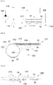
- Fig. 1 is a schematic representation of an installation 100 implemented in an aircraft according to the invention and represented schematically in Fig. 2 .
- the installation 100 comprises a fuel cell 102 which converts the chemical energy deriving from an oxidoreduction of dihydrogen and of dioxygen into electrical energy, into heat and into water.
- the aircraft 200 comprises a tank of dihydrogen and a line circuit ensuring that the fuel cell 102 is supplied with the dihydrogen.
- the fuel cell 102 is supplied with dioxygen, either from a tank of dioxygen of the aircraft 200, or by the outside air.
- dioxygen either from a tank of dioxygen of the aircraft 200, or by the outside air.
- Fig. 2 is a schematic representation of the aircraft 200 which comprises a structure 202 and engines 204.
- the structure 202 conventionally comprises a fuselage 206 and a wing 208 on either side of the fuselage 206.
- the aircraft 200 here comprises two engines 204 under each wing 208.
- the aircraft can comprise just one or more than two engines 204 under each wing 208.
- the fuel cells 102 electrically power the engines 204 which are, for example, propeller engines.
- the second heat-transfer fluid In order to control the temperature of the fuel cell 102, the latter is passed through by a heat-transfer fluid, called second heat-transfer fluid.
- the second heat-transfer fluid is generally in liquid phase.
- the second heat-transfer fluid can also be a two-phase heat-transfer fluid having a gaseous phase and a liquid phase.
- the second heat-transfer fluid can be water, or a mixture of water and additives, such as glycol water.
- the installation 100 also comprises a cooling system 104 which ensures the cooling of the second heat-transfer fluid.
- the cooling system 104 comprises at least one line 106 which takes the second heat-transfer fluid at an output of the fuel cell 102 and which reintroduces this second heat-transfer fluid at an input of the fuel cell 102.
- the line 106 and the fuel cell 102 thus form a closed loop of circulation of the second heat-transfer fluid.
- the cooling system 104 also comprises a pumping system comprising at least one pump 108 which is arranged on the line 106 to drive the second heat-transfer fluid in the line 106 between the output and the input of the fuel cell 102.
- the structure 202 comprises at least one leakproof tank 210.
- the leakproof tank 210 can be a part of the wing 208 and/or a part of the fuselage 206.
- the fuel cell 102 is in the engine 204 on the wing 208, it is preferable to provide the leakproof tank 210 in the wing 208, and if the fuel cell 102 is in the fuselage 206, it is preferable to provide the leakproof tank 210 in the fuselage 206 to reduce the length of the line 106.
- other layouts are possible.
- the leakproof tank 210 is delimited by walls of the aircraft 200 of which at least one is in contact with the air outside the aircraft 200. In the case where the leakproof tank 210 is in the wing 208, the leakproof tank 210 is delimited between the lower surface wall and the upper surface wall of the wing 208, and the two walls are in contact with the outside air. In the case where the leakproof tank 210 is in the fuselage 206 which has an inner wall and an outer wall, the leakproof tank 210 is delimited between the inner wall and the outer wall which is the wall in contact with the outside air.
- the leakproof tank 210 is filled partly with a heat-transfer fluid, called first heat-transfer fluid, which has two phases, namely a liquid phase 50 and a gaseous phase 52, within the temperature ranges considered, that is to say according to the temperature of the heat-transfer fluid coming from the fuel cell 102.
- the leakproof tank 210 forms a closed loop of circulation of the first heat-transfer fluid.
- the first heat-transfer fluid is distinct from the second heat-transfer fluid.
- the first heat-transfer fluid is water which all evaporates at approximately 100°C at ground level (in conventional atmospheric conditions) and at approximately 75°C at an altitude of 25 000 feet. Because of this, it is possible to cool this first heat-transfer fluid to a lower temperature at altitude than at ground level.
- the first heat-transfer fluid can also be a mixture of water and of additives, such as glycol water.
- the line 106 passes through the leakproof tank 210 at a height where the line 106 is immersed in the first heat-transfer fluid in liquid phase 50, that is to say more in the lower part of the leakproof tank 210.
- the first heat-transfer fluid which surrounds the line 106 picks up the calories from the second heat-transfer fluid and evaporates, then, in contact with the wall in contact with the outside air, the vapour thus given off condenses to drop back into the liquid phase 50.
- the outside air (arrows 54 along the lower surface and the upper surface) cools the wall of the leakproof tank 210 and thus makes it possible to lower the temperature of the first heat-transfer fluid and condense it. Since the first heat-transfer fluid reverts to its liquid state, and the first heat-transfer fluid considered has a significant latent heat, there is no need to install a very significant volume and mass of said first heat-transfer fluid.
- the second heat-transfer fluid can be in liquid phase and/or in gaseous phase in the line 106 between the output of the fuel cell 102 and the leakproof tank 210, and in liquid phase in the line 106 between the leakproof tank 210 and the input of the fuel cell 102.
- the line 106 can be divided into a plurality of sublines in the leakproof tank 210 as is represented in Fig. 2 .
- Fig. 3 shows the wing 208 with the plurality of sublines immersed in the first heat-transfer fluid in liquid phase 50.
- this heat exchanger 110 can be of very much smaller size than that of the state of the art, because it serves only to discharge a small part of the calories.
- This heat exchanger 110 ensures the transfer of calories from the heat-transfer fluid to a cold fluid, for example the air outside the aircraft 200. Thus, the outside air passes through the heat exchanger 110 then is rejected outside.
- the second heat-transfer fluid passes through the heat exchanger 110 and the calories from the second heat-transfer fluid are transferred to the outside air.
- This heat exchanger 110 is preferentially installed downstream of the leakproof tank 210 with respect to the direction of flow of the second heat-transfer fluid. Obviously, this heat exchanger 110 can be installed upstream of the leakproof tank 210 with respect to the direction of flow of the heat-transfer fluid.
- An overpressure system comprising at least one valve 212 can be provided at the leakproof tank 210 in order to release the pressure if the latter becomes too great.
Applications Claiming Priority (1)
| Application Number | Priority Date | Filing Date | Title |
|---|---|---|---|
| FR2100433 | 2021-01-18 |
Publications (1)
| Publication Number | Publication Date |
|---|---|
| EP4029785A1 true EP4029785A1 (fr) | 2022-07-20 |
Family
ID=74871636
Family Applications (1)
| Application Number | Title | Priority Date | Filing Date |
|---|---|---|---|
| EP22151288.2A Pending EP4029785A1 (fr) | 2021-01-18 | 2022-01-13 | Aéronef équipé d'une pile à combustible et d'une structure ayant un réservoir contenant un caloporteur assurant le refroidissement de la pile à combustible |
Country Status (3)
| Country | Link |
|---|---|
| US (1) | US11791480B2 (fr) |
| EP (1) | EP4029785A1 (fr) |
| CN (1) | CN114824356A (fr) |
Citations (4)
| Publication number | Priority date | Publication date | Assignee | Title |
|---|---|---|---|---|
| US20070158500A1 (en) * | 2006-01-06 | 2007-07-12 | Ion America Corporation | Solid oxide fuel cell system for aircraft power, heat, water, and oxygen generation |
| DE102007060428B3 (de) * | 2007-12-14 | 2009-05-07 | Airbus Deutschland Gmbh | Verdampfungsgekühltes Brennstoffzellensystem und Verfahren zum Betreiben eines verdampfungsgekühlten Brennstoffzellensystems sowie seine Verwendung in einem Luftfahrzeug |
| WO2009127652A2 (fr) * | 2008-04-16 | 2009-10-22 | Airbus Operations Gmbh | Système de dégivrage pour un avion |
| US20130199218A1 (en) * | 2012-02-03 | 2013-08-08 | Airbus Operations Gmbh | Icing protection system for an aircraft and method for operating an icing protection system |
-
2022
- 2022-01-13 US US17/574,917 patent/US11791480B2/en active Active
- 2022-01-13 EP EP22151288.2A patent/EP4029785A1/fr active Pending
- 2022-01-18 CN CN202210054139.9A patent/CN114824356A/zh active Pending
Patent Citations (4)
| Publication number | Priority date | Publication date | Assignee | Title |
|---|---|---|---|---|
| US20070158500A1 (en) * | 2006-01-06 | 2007-07-12 | Ion America Corporation | Solid oxide fuel cell system for aircraft power, heat, water, and oxygen generation |
| DE102007060428B3 (de) * | 2007-12-14 | 2009-05-07 | Airbus Deutschland Gmbh | Verdampfungsgekühltes Brennstoffzellensystem und Verfahren zum Betreiben eines verdampfungsgekühlten Brennstoffzellensystems sowie seine Verwendung in einem Luftfahrzeug |
| WO2009127652A2 (fr) * | 2008-04-16 | 2009-10-22 | Airbus Operations Gmbh | Système de dégivrage pour un avion |
| US20130199218A1 (en) * | 2012-02-03 | 2013-08-08 | Airbus Operations Gmbh | Icing protection system for an aircraft and method for operating an icing protection system |
Also Published As
| Publication number | Publication date |
|---|---|
| US20220231311A1 (en) | 2022-07-21 |
| US11791480B2 (en) | 2023-10-17 |
| CN114824356A (zh) | 2022-07-29 |
Similar Documents
| Publication | Publication Date | Title |
|---|---|---|
| US6931834B2 (en) | Cooling systems | |
| CN101821887B (zh) | 蒸发冷却的燃料电池系统以及运行蒸发冷却的燃料电池系统的方法 | |
| US9162770B2 (en) | Electric drive device for an aircraft | |
| US4505124A (en) | Heat management system for aircraft | |
| US8881764B2 (en) | Offset ambient level fuel feed system | |
| CA2713209C (fr) | Systeme et procede de reduction des polluants dans les gaz d'echappement des groupes motopropulseurs | |
| US20100287955A1 (en) | Two-phase hydrogen pump and method | |
| EP4029785A1 (fr) | Aéronef équipé d'une pile à combustible et d'une structure ayant un réservoir contenant un caloporteur assurant le refroidissement de la pile à combustible | |
| US11820473B2 (en) | Hull thermal management system | |
| US9853301B2 (en) | Thermal conditioning fluids for an underwater cryogenic storage vessel | |
| SE418769B (sv) | Anordning for avtappning av koldmedier fran kyl- och vermeaggregat | |
| US20240043132A1 (en) | Cooling system for an aircraft, aircraft having a cooling system, and method for cooling an electric propulsion system of an aircraft | |
| CN103456976A (zh) | 用于提供电功率的系统和方法 | |
| US2640627A (en) | Vapor recovery system for fuel tanks | |
| EP2592000A1 (fr) | Réservoir de carburant pour aéronef pourvu d'un système de chauffage à combustible et système de chauffage de carburant pour aéronef équipé d'un tel réservoir | |
| CN106240784A (zh) | 一种长航时飞艇 | |
| CN111435056B (zh) | 热交换器 | |
| RU2661178C1 (ru) | Система обеспечения теплового режима приборного отсека летательного аппарата | |
| US10717535B2 (en) | Two-phase type heat transfer device for heat sources operating at a wide temperature range | |
| US2694980A (en) | Fuel pumping system | |
| US20180023900A1 (en) | Diphasic cooling loop with satellite evaporators | |
| EP3922498B1 (fr) | Réservoir de détente pour un véhicule avec deux lignes de refroidissement, système de refroidissement et procédé de remplissage de réservoir de détente | |
| ES2221048T3 (es) | Combustible refrigerado para motores. | |
| CN113423235B (zh) | 一种用于机载电子设备的冷却系统 | |
| GB2514813A (en) | Fuel cell system and associated method of operation |
Legal Events
| Date | Code | Title | Description |
|---|---|---|---|
| PUAI | Public reference made under article 153(3) epc to a published international application that has entered the european phase |
Free format text: ORIGINAL CODE: 0009012 |
|
| STAA | Information on the status of an ep patent application or granted ep patent |
Free format text: STATUS: THE APPLICATION HAS BEEN PUBLISHED |
|
| AK | Designated contracting states |
Kind code of ref document: A1 Designated state(s): AL AT BE BG CH CY CZ DE DK EE ES FI FR GB GR HR HU IE IS IT LI LT LU LV MC MK MT NL NO PL PT RO RS SE SI SK SM TR |
|
| STAA | Information on the status of an ep patent application or granted ep patent |
Free format text: STATUS: REQUEST FOR EXAMINATION WAS MADE |
|
| 17P | Request for examination filed |
Effective date: 20230118 |
|
| RBV | Designated contracting states (corrected) |
Designated state(s): AL AT BE BG CH CY CZ DE DK EE ES FI FR GB GR HR HU IE IS IT LI LT LU LV MC MK MT NL NO PL PT RO RS SE SI SK SM TR |
|
| STAA | Information on the status of an ep patent application or granted ep patent |
Free format text: STATUS: EXAMINATION IS IN PROGRESS |
|
| 17Q | First examination report despatched |
Effective date: 20231006 |