EP4029761A1 - Fahrzeuglenksystem und verfahren zur steuerung eines lenkwinkels eines fahrzeugrades - Google Patents
Fahrzeuglenksystem und verfahren zur steuerung eines lenkwinkels eines fahrzeugrades Download PDFInfo
- Publication number
- EP4029761A1 EP4029761A1 EP21151260.3A EP21151260A EP4029761A1 EP 4029761 A1 EP4029761 A1 EP 4029761A1 EP 21151260 A EP21151260 A EP 21151260A EP 4029761 A1 EP4029761 A1 EP 4029761A1
- Authority
- EP
- European Patent Office
- Prior art keywords
- steering
- vehicle
- angle
- wheel
- support motor
- Prior art date
- Legal status (The legal status is an assumption and is not a legal conclusion. Google has not performed a legal analysis and makes no representation as to the accuracy of the status listed.)
- Pending
Links
- 238000000034 method Methods 0.000 title claims abstract description 27
- 238000012545 processing Methods 0.000 claims abstract description 62
- 238000013519 translation Methods 0.000 claims description 9
- 238000004364 calculation method Methods 0.000 claims description 7
- 238000004590 computer program Methods 0.000 claims description 7
- 230000006978 adaptation Effects 0.000 claims description 2
- 230000001419 dependent effect Effects 0.000 claims description 2
- 230000000712 assembly Effects 0.000 abstract description 2
- 238000000429 assembly Methods 0.000 abstract description 2
- 230000008901 benefit Effects 0.000 description 11
- 230000008859 change Effects 0.000 description 8
- 238000005096 rolling process Methods 0.000 description 6
- 238000005259 measurement Methods 0.000 description 3
- 108010066114 cabin-2 Proteins 0.000 description 2
- 238000004891 communication Methods 0.000 description 2
- 230000000694 effects Effects 0.000 description 2
- 230000009471 action Effects 0.000 description 1
- 230000006399 behavior Effects 0.000 description 1
- 230000000295 complement effect Effects 0.000 description 1
- 230000001010 compromised effect Effects 0.000 description 1
- 238000010276 construction Methods 0.000 description 1
- 239000000446 fuel Substances 0.000 description 1
- 230000006870 function Effects 0.000 description 1
- 230000007257 malfunction Effects 0.000 description 1
- 238000012986 modification Methods 0.000 description 1
- 230000004048 modification Effects 0.000 description 1
- 230000003287 optical effect Effects 0.000 description 1
- 230000002085 persistent effect Effects 0.000 description 1
- 230000004044 response Effects 0.000 description 1
- 239000007787 solid Substances 0.000 description 1
- 239000000725 suspension Substances 0.000 description 1
Images


Classifications
-
- B—PERFORMING OPERATIONS; TRANSPORTING
- B62—LAND VEHICLES FOR TRAVELLING OTHERWISE THAN ON RAILS
- B62D—MOTOR VEHICLES; TRAILERS
- B62D5/00—Power-assisted or power-driven steering
- B62D5/04—Power-assisted or power-driven steering electrical, e.g. using an electric servo-motor connected to, or forming part of, the steering gear
- B62D5/0457—Power-assisted or power-driven steering electrical, e.g. using an electric servo-motor connected to, or forming part of, the steering gear characterised by control features of the drive means as such
- B62D5/046—Controlling the motor
-
- B—PERFORMING OPERATIONS; TRANSPORTING
- B62—LAND VEHICLES FOR TRAVELLING OTHERWISE THAN ON RAILS
- B62D—MOTOR VEHICLES; TRAILERS
- B62D7/00—Steering linkage; Stub axles or their mountings
- B62D7/06—Steering linkage; Stub axles or their mountings for individually-pivoted wheels, e.g. on king-pins
- B62D7/08—Steering linkage; Stub axles or their mountings for individually-pivoted wheels, e.g. on king-pins the pivotal axes being situated in a single plane transverse to the longitudinal centre line of the vehicle
- B62D7/09—Steering linkage; Stub axles or their mountings for individually-pivoted wheels, e.g. on king-pins the pivotal axes being situated in a single plane transverse to the longitudinal centre line of the vehicle characterised by means varying the ratio between the steering angles of the steered wheels
-
- B—PERFORMING OPERATIONS; TRANSPORTING
- B62—LAND VEHICLES FOR TRAVELLING OTHERWISE THAN ON RAILS
- B62D—MOTOR VEHICLES; TRAILERS
- B62D7/00—Steering linkage; Stub axles or their mountings
- B62D7/06—Steering linkage; Stub axles or their mountings for individually-pivoted wheels, e.g. on king-pins
- B62D7/14—Steering linkage; Stub axles or their mountings for individually-pivoted wheels, e.g. on king-pins the pivotal axes being situated in more than one plane transverse to the longitudinal centre line of the vehicle, e.g. all-wheel steering
- B62D7/15—Steering linkage; Stub axles or their mountings for individually-pivoted wheels, e.g. on king-pins the pivotal axes being situated in more than one plane transverse to the longitudinal centre line of the vehicle, e.g. all-wheel steering characterised by means varying the ratio between the steering angles of the steered wheels
- B62D7/159—Steering linkage; Stub axles or their mountings for individually-pivoted wheels, e.g. on king-pins the pivotal axes being situated in more than one plane transverse to the longitudinal centre line of the vehicle, e.g. all-wheel steering characterised by means varying the ratio between the steering angles of the steered wheels characterised by computing methods or stabilisation processes or systems, e.g. responding to yaw rate, lateral wind, load, road condition
-
- B—PERFORMING OPERATIONS; TRANSPORTING
- B62—LAND VEHICLES FOR TRAVELLING OTHERWISE THAN ON RAILS
- B62D—MOTOR VEHICLES; TRAILERS
- B62D6/00—Arrangements for automatically controlling steering depending on driving conditions sensed and responded to, e.g. control circuits
- B62D6/002—Arrangements for automatically controlling steering depending on driving conditions sensed and responded to, e.g. control circuits computing target steering angles for front or rear wheels
-
- B—PERFORMING OPERATIONS; TRANSPORTING
- B62—LAND VEHICLES FOR TRAVELLING OTHERWISE THAN ON RAILS
- B62D—MOTOR VEHICLES; TRAILERS
- B62D7/00—Steering linkage; Stub axles or their mountings
- B62D7/06—Steering linkage; Stub axles or their mountings for individually-pivoted wheels, e.g. on king-pins
- B62D7/08—Steering linkage; Stub axles or their mountings for individually-pivoted wheels, e.g. on king-pins the pivotal axes being situated in a single plane transverse to the longitudinal centre line of the vehicle
-
- B—PERFORMING OPERATIONS; TRANSPORTING
- B62—LAND VEHICLES FOR TRAVELLING OTHERWISE THAN ON RAILS
- B62D—MOTOR VEHICLES; TRAILERS
- B62D7/00—Steering linkage; Stub axles or their mountings
- B62D7/20—Links, e.g. track rods
-
- B—PERFORMING OPERATIONS; TRANSPORTING
- B62—LAND VEHICLES FOR TRAVELLING OTHERWISE THAN ON RAILS
- B62D—MOTOR VEHICLES; TRAILERS
- B62D5/00—Power-assisted or power-driven steering
-
- B—PERFORMING OPERATIONS; TRANSPORTING
- B62—LAND VEHICLES FOR TRAVELLING OTHERWISE THAN ON RAILS
- B62D—MOTOR VEHICLES; TRAILERS
- B62D5/00—Power-assisted or power-driven steering
- B62D5/04—Power-assisted or power-driven steering electrical, e.g. using an electric servo-motor connected to, or forming part of, the steering gear
Definitions
- the present disclosure relates to a vehicle steering system.
- the present disclosure also relates to a method for controlling a steering angle of a vehicle wheel.
- the present disclosure relates to a computer program, to a computer readable medium and to a processing circuitry for controlling a steering angle of a vehicle wheel.
- the invention can be applied in heavy-duty vehicles, such as trucks, buses and construction equipment. Although the invention will be described with respect to a truck, the invention is not restricted to this particular vehicle, but may also be used in other vehicles such as cars.
- electrically supported vehicle steering systems which complement the mechanical steering systems.
- Such electrically supported vehicle steering systems may be provided, for instance, to reduce vibration input to the steering wheel of a vehicle.
- Another functionality may be to provide forced feedback for guiding the driver.
- a further functionality may be to provide parking assistance.
- An object of the invention is to provide a vehicle steering system and a method for controlling a steering angle of a vehicle wheel, which at least partly alleviate the drawbacks of the prior art. This object is accomplished by a vehicle steering system and a method as disclosed in the accompanying independent claims.
- the present inventive concept is based on the realization that by providing an electrical/data dependency between the left and the right wheel, specifically an electrical/data dependency between a left steering assembly and a right steering assembly, instead of a mechanical dependency, the relative steering angle of the two wheels may be adjusted in different driving scenarios.
- the inventors have realized that by analysing a status of one of the steering assemblies associated with one of the wheels, it is possible to effectively adjust the steering angle of the other wheel.
- a vehicle steering system comprising:
- a vehicle steering system which comprises a processing circuitry that receives information about parameter values measured for the first steering assembly linked to the first road wheel, it can calculate an appropriate steering angle for the second road wheel. For instance, if the processing circuitry notes that the current vehicle operating condition is straight forward driving, it may control the second road wheel to have substantially the opposite steering angle as the first road wheel (for example, if the input signals to the processing circuitry are indicative of the left road wheel being at a steering angle of +0.1 (of any suitable unit), then it may send control signals that result in -0.1 for the right road wheel). This reduces rolling resistance. In other vehicle operating conditions, other control signals may be sent.
- the processing circuitry may send appropriate control signals, which may suitably vary over time. For example, if the left road wheel is kept at a steering angle of 1 for a period of time, such as a plurality of seconds, then the right road wheel may be controlled to gradually increase the steering angle, say from 0.2 to 0.8 for good lateral force control.
- said first input signals may suitably contain data representative of the steering angle of the first road wheel.
- vehicle steering system comprises a steering wheel, it is not limited to implementation in driver-operated vehicles.
- the present vehicle steering system may also be used in autonomous vehicles.
- the processing circuitry may send its control signals based on current vehicle operating conditions. However, it may also base its control signals on a desired vehicle operating condition.
- the processing circuitry is configured to also base its calculations of said desired steering angle on a current or a desired vehicle operating condition. By taking into account a current or desired vehicle operating condition, an even more accurate control may be made. For instance, the processing circuitry may make different calculations in different scenarios depending on if the vehicle is driving fast or slowly, or if the road surface is smooth or uneven, etc. Furthermore, it may in some exemplary embodiments base its control signals on a predicted vehicle operating condition.
- the processing circuitry comprises or has communicative access to an electronic memory in which a set of rules are stored, wherein each rule is associated with one or more predefine vehicle operating conditions, wherein, for a certain current or desired vehicle operating condition, the processing circuitry is configured to also base its calculations of said desired steering angle on a rule associated with said certain current or desired vehicle operating condition.
- the steering angle may be adapted not only based on input signals which relate to the steering angle of the first road wheel, but also to other general vehicle operating conditions.
- the speed of the vehicle may be such a condition which may suitably be taken into account when calculating the desired steering angle for the second road wheel.
- the processing circuitry may suitably have an interface for receiving sensor data signals from external sensors or via a vehicle control unit, etc.
- the processing circuitry is configured to receive from the second steering assembly second input signals, the second input signals comprising one or more current steering parameter values measured for the second steering assembly, wherein, the processing circuitry is configured to control the second support motor, by means of said control signals, also based on the received second input signals.
- the processing circuitry may calculate how much additional or how much less torque the second support motor should apply to the steering linkage. For instance, an uneven road surface may affect the forces acting on the road wheel and the thus the steering linkage differently than when travelling on a smooth road surface. Accordingly, different amounts of compensation may be desirable depending on the current steering parameter values measured for the second steering assembly.
- the vehicle steering system comprises a connecting member assembly, wherein the connecting member assembly comprises
- the connecting member assembly may be provided at different locations, which may affect the configuration of the connecting member assembly. Considering the fact that in a steering system, and in particular the steering assembly, there may be various links and connections between components performing different movements, such as pivoting, rotational, translational movements. Depending on which type of components of the steering assembly that you want to connect the connecting member assembly, the relative motion between the first and the second connecting member is suitably adapted to the type of movement performed by those components.
- the connecting member assembly may be connected to components which are movable closer to or further away from the central longitudinal axis of the vehicle (i.e. the roll axis), such as by a pivoting motion.
- the pivoting may suitably be around an axis parallel to the yaw axis of the vehicle.
- the first and the second connecting members are thus suitably movable relative to each other in a direction perpendicular to the roll axis.
- the first and the second connecting members are movable relative to each other in a direction parallel to the pitch axis of the vehicle.
- the central joint may thus be a translation joint. This is reflected in the following exemplary embodiment.
- the central joint is a translation joint for enabling relative translational movement between the first connecting member and the second connecting member when the relative angle between the first steering angle and the second steering angle changes.
- the total length of the connecting member assembly is variable.
- the first connecting member may be connected to a left side knuckle
- the second connecting member may be connected to the right side knuckle.
- Such a translation joint may suitably include a safety translation stop.
- a safety translation stop may be provided for creating a mechanical safety connection between the first steering assembly and the second steering assembly (such as between the exemplified left and right side knuckles) if electric and/or hydraulic support fails (e.g. failure of second support motor).
- the connecting member assembly may be connected to components which are movable forwards or rearwards in the longitudinal direction of the vehicle (such as by a pivoting motion in a vertical plane which is parallel to the roll axis).
- the first and the second connecting members are suitably movable relative to each other in a rotational direction, such as in a rotational motion around an axis parallel to the pitch axis.
- the central joint may be a rotation joint. This is reflected in the following exemplary embodiment,
- the central joint is a rotation joint for enabling relative rotational movement between the first connecting member and the second connecting member when the relative angle between the first steering angle and the second steering angle changes.
- the first connecting member may be connected to a left side pitman arm
- the second connecting member may be connected to a right side pitman arm. Pivoting of the pitman arms causes rotation of the respective connecting member.
- the first and second connecting members will rotate relative to each other within the rotation joint.
- Such a rotation joint may suitably include a safety rotational stop.
- a safety rotational stop may be provided for creating a mechanical safety connection between the first and second steering assembly, if electric and/or hydraulic support fails (e.g. failure of second support motor).
- a gear box as an additional security feature. If the second support motor fails, the connecting member assembly still functions as a mechanical link between the first steering assembly and the second steering assembly, via the gear box. The rotational direction of the connecting member assembly is changed by the gear box to an opposite rotational direction for the connected component of the second steering assembly, which will be required for turning the second road wheel in the same direction as the first road wheel. This will be explained more clearly in connection with the discussion of the drawings. It should, however, be noted that in normal functional operation, the gear box is not in operative action, and the control of the second steering assembly may be done electrically and/or hydraulically, by means of the second support motor.
- said one or more steering parameter values measured for the first steering assembly is one of, or a combination of:
- said one or more steering parameter values measured for the second steering assembly is one of, or a combination of:
- said first support motor is an electric or hydraulic support motor
- said second support motor is an electric or hydraulic support motor.
- Electric power steering and hydraulic power steering systems each have their advantages. Electric support motors are relatively easy to calibrate and are often more lightweight then hydraulic motors with its accessories. On the other hand, some drivers are of the opinion that hydraulic power steering provides a better feel for the road.
- the processing circuitry is configured to calculate said desired steering angle so as to allow adaptation for any one of:
- a vehicle which comprises a vehicle steering system according to the first aspect, including any embodiment thereof.
- the advantages of the vehicle of the second aspect largely correspond to the advantages of the vehicle steering system of the first aspect, including any embodiment thereof.
- a method for controlling a steering angle of a vehicle wheel the method being implemented in a vehicle steering system which comprises:
- the method is carried out for a vehicle steering system according to the first aspect, including any embodiment thereof, or a vehicle according to the second aspect, including any embodiment thereof.
- a computer program comprising program code means for performing the method according to the third aspect, including any embodiments thereof, when said program is run on a computer.
- the advantages of the computer program of the fourth aspect largely correspond to those of the other aspects, including any embodiments thereof.
- a computer readable medium carrying a computer program comprising program code means for performing the method according to the third aspect, including any embodiments thereof, when said program product is run on a computer.
- the advantages of the computer readable medium of the fifth aspect largely correspond to the advantages of the other aspects, including any embodiments thereof.
- a processing circuitry for controlling a steering angle of a vehicle wheel, the processing circuitry being configured to perform the method according the third aspect, including any embodiments thereof.
- the advantages of the processing circuitry of the sixth aspect largely correspond to the advantages of the other aspects, including any embodiments thereof.
- the processing circuitry of the sixth aspect and the processing circuitry used in the vehicle steering system of the first aspect may include a microprocessor, microcontroller, programmable digital signal processor or another programmable device.
- the processing circuitry may also, or instead, include an application specific integrated circuit, a programmable gate array or programmable array logic, a programmable logic device, or a digital signal processor. Where it includes a programmable device such as the microprocessor, microcontroller or programmable digital signal processor mentioned above, the processor may further include computer executable code that controls operation of the programmable device.
- Fig. 1 illustrates a vehicle 1 according to at least one exemplary embodiment of the invention.
- the exemplary illustration in Fig. 1 shows a tractor unit for towing a trailer unit (not shown), which together make up a semitrailer vehicle.
- the vehicle 1 may be a different type of vehicle for cargo transport, such as a truck, or a truck with a dolly unit arranged to tow a trailer unit, etc.
- the inventive concept is not limited to heavy duty vehicles, but may also be implemented in other vehicles, such as cars.
- the vehicle 1 has a cabin 2 in which a driver me operate the vehicle.
- the vehicle 1 may be autonomous.
- the illustrated vehicle 1 is supported on road wheels 4.
- vehicle in Fig. 1 only has two axles carrying road wheels 4, the inventive concept is applicable to vehicles having more axles carrying road wheels, such as in the above-mentioned different types of vehicles.
- the road wheels 4 on the front axle are steered wheels. In other exemplary embodiments, other axles may also be provided with steered wheels.
- the vehicle 1 is provided with power assisted steering, such that when a steering wheel in the cabin 2 is turned, support motors provide additional force to turn the front road wheels 4.
- the vehicle 1 may suitably comprise a vehicle steering system in accordance with the general inventive concept. Two exemplary illustrations of such a vehicle steering system are presented in Figs. 2 and 3 .
- Fig. 2 illustrates a vehicle steering system 10 according to at least one exemplary embodiment of the invention.
- the vehicle steering system 10 comprises a steering wheel 12. A driver may turn the steering wheel 12 in order to turn the vehicle. However, as mentioned above, the general inventive concept is also applicable to autonomous vehicles.
- the vehicle steering system 10 also comprises a first steering assembly.
- the steering wheel is, via a shaft, connected to the first steering assembly 20A, which in its turn is connected to a first road wheel at a first end of a wheel axle (not shown).
- the first road wheel is, for sake of clarity not illustrated in Fig. 2 .
- the second road wheel 4 is, however, illustrated and it should be understood that the actual mounting of the first road wheel may suitably correspond to the mounting of the second road wheel 4.
- the first road wheel should in the example be understood to represent a left road wheel, however in other exemplary embodiments it could be a road wheel on the right hand side.
- the first steering assembly 20A comprises a first steering linkage 22A which is mechanically connected to the first road wheel.
- the first steering assembly 20A also comprises a first support motor 24A which is operatively connected to the steering wheel 12.
- the rotation and torque of the steering wheel 12 gives input to the first support motor 24A, in particular to a steering gear of, or associated to, the first support motor 24A for electrical and/or hydraulic support.
- the first support motor 24A is also operatively connected to the first steering linkage 22A.
- the first steering linkage 22A comprises a first Pitman arm 26A, a first link rod 28A and a first steering arm 30A.
- the steering gear of the first support motor 24A rotates the first Pitman arm 26A which in turn pushes or pulls the first link rod 28A to the first steering arm 30A (push or pull depends on which direction the steering wheel 12 is turned).
- Rotation of the first steering arm 30A and the torque provided by the first steering arm 30A causes a first wheel knuckle 32A to turn.
- the first road wheel turns with the first wheel knuckle 32A.
- the steering wheel 12 is configured to control a steering angle of the first road wheel via the first support motor 24A actuating the first steering linkage 22A.
- the vehicle steering system 10 also comprises a second steering assembly 20B.
- the second steering assembly 20B comprises a second steering linkage 22B which is mechanically connected to the second road wheel 4, and a second support motor 24B which is operatively connected to the second steering linkage 22B.
- the second steering linkage 22B comprises, similarly to the first steering linkage, a second Pitman arm 26B, a second link rod 28B and a second steering arm 30B.
- the vehicle steering system 10 further comprises a processing circuitry 50 which is configured to receive from the first steering assembly 20A first input signals 34A.
- the first input signals 34A comprises one or more steering parameter values measured for the first steering assembly 20A.
- the first input signals 34A may be the torque provided by the first support motor 24A or the steering gear of the first support motor 24A and/or a steering gear angle.
- Other conceivable input signals may be strain measurement signals on the push and pull force at the first link rod 28A.
- Another possibility is to have wheel knuckle angle sensors at the wheel rotation axis.
- the processing circuitry 50 is configured to calculate a desired steering angle of the second road wheel 4 and to send control signals 52 to the second support motor 24B so as to actuate the second steering linkage 22B such that said desired steering angle of the second road wheel 4 is obtained.
- the second support motor 24B will provide an electrical and/or hydraulic steering torque such that the steering gear of the second support motor 24B rotates the second Pitman arm 26B, the rotation of which causes the second link rod 28B to be pushed/pulled, which in turn causes the second steering arm 30Bto rotate, and thus the second wheel knuckle 32B and the second wheel 4 to turn.
- first steering assembly 20A and the second steering assembly 20B are assembled in such way that, in order for both the first and second road wheel to turn in the same direction (for example turn right), the first link rod 28A and the second link rod 28B will be moved in opposite directions.
- first Pitman arm 26A will be engaged by the steering gear of the first support motor 24A to push the first link rod 28A, while the second Pitman arm 26B will be engaged to pull the second link rod 28B.
- first components have been illustrated as left side components, and all of the second components have been illustrated as right side components. It should, however, be understood that in other exemplary embodiments the first components may be on the right side of the vehicle and the second components may be on the left side of the vehicle.
- the processing circuitry 50 may, suitably, be configured to also base its calculations of said desired steering angle on a current or a desired vehicle operating condition. Accordingly, the processing circuitry 50 may control the second road wheel 4 (via the second support motor 24A and second steering linkage 22A) such that in one vehicle operating condition the relative difference in steering angle between the first and the second road wheel is different (larger or smaller) than the relative difference in steering angle in another vehicle operating condition. For instance, taking the same curve in different velocities may suitably result in different steering angles for the second road wheel 4, although the steering angle may be the same for the first road wheel. Another example, is straight driving versus driving through a curve.
- the processing circuitry 50 compensates for toe in/toe out. Through a curve, the processing circuitry 50 calculates a suitably steering angle of the second road wheel 4, which oftentimes will be different from the current steering angle of the first road wheel.
- the processing circuitry 50 may be provided using any combination of one or more of a suitable central processing unit CPU, multiprocessor, microcontroller, digital signal processor DSP, etc., capable of executing software instructions stored in a computer program product, e.g. in the form of a storage medium.
- the processing circuitry 50 may further be provided as at least one application specific integrated circuit ASIC, or field programmable gate array FPGA.
- the processing circuitry configured to perform a set of operations, or steps, such as the inventive method discussed in this disclosure.
- the storage medium may store the set of operations
- the processing circuitry may be configured to retrieve the set of operations from the storage medium to perform the set of operations.
- the set of operations may be provided as a set of executable instructions.
- the processing circuitry 50 is thereby arranged to execute exemplary methods as herein disclosed.
- the storage medium may also comprise persistent storage, which, for example may be any single one or combination of magnetic memory, optical memory, solid state memory or even remotely mounted memory.
- the processing circuitry 50 may further comprise an interface for communications with at least one external device such as the support motors, sensors, etc..
- the interface may comprise one or more transmitters and receivers, comprising analogue and digital components and a suitable number of ports for wireline or wireless communication.
- the processing circuitry 50 may thus send data and control signals to the interface and the storage medium, and may receiving data and reports from the interface, and may retrieve data and instructions form the storage medium.
- the processing circuitry 50 may, suitably, comprise or have communicative access to an electronic memory (such as in the above-mentioned storage medium) in which a set of rules are stored, wherein each rule is associated with one or more predefine vehicle operating conditions. For a certain current or desired vehicle operating condition, the processing circuitry 50 is configured to also base its calculations of said desired steering angle on a rule associated with said certain current or desired vehicle operating condition.
- an electronic memory such as in the above-mentioned storage medium
- the processing circuitry 50 is configured to also base its calculations of said desired steering angle on a rule associated with said certain current or desired vehicle operating condition.
- the set of rules may suitably be provided in the form of a look up table and/or as algorithms.
- Table to illustrate the algorithms for guiding the steering angles Left side gear A1 Right side gear B1 Time A1t A1a Bit B1a Minimizing rolling resistance (straight forward driving) 0 1,00 0,80 -1,00 -0,80 1 0,80 0,65 -0,80 -0,65 2 0,40 0,30 -0,40 -0,30
- Example A 3 0,10 0,15 -0,10 -0,15 4 0,02 0,10 -0,02 -0,10 5 0,00 0,10 0,00 -0,10 Lateral force control (curve driving) 0 0,7 1 0,3 0,2 1 0,675 1 0,325 0,25 2 0,575 1 0,375 0,5
- A1a is the left steering gear angle, activated by the driver/steering wheel 12.
- Bit is the torque applied at the second (right) steering gear of the second support motor 24B, activated by the processing circuitry 50.
- B1a is right steering gear angle, activated by the processing circuitry 50.
- Figs. 4-7 illustrate graphs of different driving scenarios, showing the relations between torque and angle of the steering gear of the first support motor and the steering gear of the second support motor.
- a purpose of the vehicle steering system is to control the first and second steering angles, i.e. to control the angles of the wheel knuckles (32A and 32B in Fig. 2 ), and thus the road wheels. These angles of the wheel knuckles have a direct relation to the steering gear angles A1a and B1a via the steering linkages (22A and 22B in Fig. 2 ).
- Fig. 4 illustrates minimizing rolling resistance (straight forward driving).
- the second steering gear angle B1a is adjusted to minimize the steering gear torque on both the left and right side, i.e. both the first torque A1t and second torque B1t.
- the driver adjusts the straight forward position at the same time.
- the difference between the first and the second steering gear angle (A1a - B1a) could be different on different suspension types and also due to tire rolling resistance or axle load, but the adjustment by the processing circuitry may suitably optimize independent of this (i.e. minimize the steering gear torques).
- Fig. 5 illustrates lateral force control (curve driving).
- the lateral force is adjusted to 50/50 by changing the second steering gear angle B1a to increase the torque Bit at the second steering gear to the same level as the torque A1t at the first steering gear.
- the first steering gear angle A1a has been fixed.
- the illustrated effect could also be used to change understeering or oversteering behaviour, due to the possibility to change lateral response between left and right side and also at the total average steering angle (A1a + B1a)/2.
- Fig. 6 illustrates maximizing turnability (maximizing cut angle).
- the right side second steering gear angle B1a is adjusted to its maximum (following the (left side) first steering gear angle A1a).
- the needed torque in this example could change sign if a self-steering angle is reached and then only a smaller torque is needed to guide the second steering angle B1a to its maximum.
- Fig. 7 illustrates minimizing rolling resistance (small steering manoeuvres at high driving speed).
- the optimal angle is in the prior art compromised by setting a linkage geometry to a fixed setting, which is only optimal for a fixed wheel base and a chosen steering angle.
- the vehicle steering system may also comprise a self-learning system that generates the optimal signal for adjusting the second steering gear angle B1a in relation to the first steering gear angle A1a when driving faster than a certain speed.
- the processing circuitry 50 may, suitably, be configured to receive from the second steering assembly 20B second input signals 34B, the second input signals 34B comprising one or more current steering parameter values measured for the second steering assembly 20B, wherein, the processing circuitry 50 is configured to control the second support motor 24B, by means of said control signals 52, also based on the received second input signals 24B.
- the vehicle steering system 10 may suitably comprise a connecting member assembly, for steering redundancy.
- a connecting member assembly for steering redundancy.
- the connecting member assembly 60 comprises a central joint 62, here in the form of a rotation joint.
- the connecting member assembly 60 further comprises a first connecting member 64 extending from the first steering assembly 20A to the one side of the central joint 62 and a second connecting member 66 extending from the second steering assembly 20B to another (here, to the opposite) side of the central joint 62.
- the first connecting member 64 is connected to the first support motor 24A and configured to rotate with the first support motor 24A (or its steering gear).
- the second connecting member 66 is connected to the second support motor 24B and configured to rotate with the second support motor 24B (or its steering gear).
- the first connecting member 64 and the second connecting member 66 are movable relative to each other in the central joint 62. More specifically, since the central joint 62 is embodied as a rotation joint, it enables a relative rotational movement between the first connecting member 64 and the second connecting member 66 when the relative angle between the first steering angle and the second steering angle changes, i.e. when the relative angle between the two road wheels changes.
- the connecting member assembly 60 provides added stability to the vehicle steering system 10, but because of the first and second connecting members 64, 66 being allowed to rotate relative to each other under normal operation, the angle of the second road wheel 4 may be freely adjusted without affecting the first road wheel. In other words, the controlling of the second support motor 24B (by means of the processing circuitry 50) will not provide any substantial mechanical effect on the first support motor 24A. The first connecting member 64 will still rotate with the first support motor 24A while the second connecting member 66 will still rotate with the second support motor 24B.
- the connecting member assembly 60 of Fig. 2 also comprises a safety feature for the unexpected event that the electric/hydraulic power steering at the second steering assembly 20B should fail/malfunction.
- the central joint 62 may include a safety rotational stop (not shown) which creates a mechanical safety connection between the first support motor 24A (steering gear) and the second support motor 24B (steering gear) if electrical/hydraulic support fails.
- the first connecting member 64 will, via the central joint 62, bring along the second connecting member 66 in its direction of rotation (possibly with some delay until the safety rotational stop is engaged).
- the vehicle steering system 10 in Fig. 2 additionally comprises a gear box 68, which changes the rotational direction.
- the gear box 68 changes the rotational direction such that the steering gear of the second support motor 24B will rotate in an opposite direction to the steering gear of the first support motor 24A, and consequently the Pitman arms 26A, 26B and the link rods 28A, 28B will also have opposite movements, thus resulting in both road wheels turning in the same direction.
- the central joint 72 of the connecting member assembly 70 is in the form of a translation joint.
- the translation joint enables relative translational movement between the first connecting member 74 and the second connecting member 76 when the relative angle between the first steering angle and the second steering angle changes.
- the first connecting member 74 and/or the second connecting member 76 moves within the central joint 72.
- the effective length of the connecting member assembly 70 is variable and dependent on the relative angle between the first road wheel and the second road wheel 4.
- the first connecting member 74 may suitably be connected to an arm at the first wheel knuckle 32A and the second connecting member 76 may suitably be connected to an arm at the second wheel knuckle 32B.
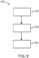
- Fig. 8 illustrates a method 100 for controlling a steering angle of a vehicle wheel, the method 100 being implemented in a vehicle steering system which comprises:
- the method 100 comprises:
- the method 100 and any embodiment thereof may suitably be carried out for a vehicle steering system (such as illustrated in Figs. 2 and 3 ) and/or a vehicle (such as illustrated in Fig. 1 ) as presented in this disclosure.
Landscapes
- Engineering & Computer Science (AREA)
- Chemical & Material Sciences (AREA)
- Combustion & Propulsion (AREA)
- Transportation (AREA)
- Mechanical Engineering (AREA)
- Physics & Mathematics (AREA)
- Mathematical Physics (AREA)
- Theoretical Computer Science (AREA)
- Steering Control In Accordance With Driving Conditions (AREA)
Priority Applications (3)
| Application Number | Priority Date | Filing Date | Title |
|---|---|---|---|
| EP21151260.3A EP4029761A1 (de) | 2021-01-13 | 2021-01-13 | Fahrzeuglenksystem und verfahren zur steuerung eines lenkwinkels eines fahrzeugrades |
| US17/557,127 US20220219752A1 (en) | 2021-01-13 | 2021-12-21 | Vehicle steering system and method for controlling a steering angle of a vehicle wheel |
| CN202111645177.3A CN114763179A (zh) | 2021-01-13 | 2021-12-29 | 车辆转向系统以及控制车辆车轮的转向角的方法 |
Applications Claiming Priority (1)
| Application Number | Priority Date | Filing Date | Title |
|---|---|---|---|
| EP21151260.3A EP4029761A1 (de) | 2021-01-13 | 2021-01-13 | Fahrzeuglenksystem und verfahren zur steuerung eines lenkwinkels eines fahrzeugrades |
Publications (1)
| Publication Number | Publication Date |
|---|---|
| EP4029761A1 true EP4029761A1 (de) | 2022-07-20 |
Family
ID=74180958
Family Applications (1)
| Application Number | Title | Priority Date | Filing Date |
|---|---|---|---|
| EP21151260.3A Pending EP4029761A1 (de) | 2021-01-13 | 2021-01-13 | Fahrzeuglenksystem und verfahren zur steuerung eines lenkwinkels eines fahrzeugrades |
Country Status (3)
| Country | Link |
|---|---|
| US (1) | US20220219752A1 (de) |
| EP (1) | EP4029761A1 (de) |
| CN (1) | CN114763179A (de) |
Cited By (1)
| Publication number | Priority date | Publication date | Assignee | Title |
|---|---|---|---|---|
| WO2023019276A1 (en) * | 2021-08-13 | 2023-02-16 | China Automotive Systems, Inc. | Electric steering assemblies for commercial vehicles |
Families Citing this family (1)
| Publication number | Priority date | Publication date | Assignee | Title |
|---|---|---|---|---|
| US11970231B2 (en) * | 2021-05-13 | 2024-04-30 | Toyota Motor Engineering & Manufacturing North America, Inc. | Causing a difference between steering angles of front wheels or rear wheels of a vehicle in a park mode |
Citations (3)
| Publication number | Priority date | Publication date | Assignee | Title |
|---|---|---|---|---|
| US20040026158A1 (en) * | 2000-03-27 | 2004-02-12 | Peter Rieth | Vehicle system and axle guide module for a vehicle steering system |
| EP2759458B1 (de) * | 2013-01-28 | 2015-04-08 | Fiat Group Automobiles S.p.A. | Elektrische Servolenkung für ein Kraftfahrzeug |
| WO2020111997A1 (en) * | 2018-11-28 | 2020-06-04 | Sentient Ip Ab | A power assisted steering system arrangement |
Family Cites Families (14)
| Publication number | Priority date | Publication date | Assignee | Title |
|---|---|---|---|---|
| CN100436227C (zh) * | 2003-10-02 | 2008-11-26 | 日产自动车株式会社 | 车辆转向装置 |
| JP2005329784A (ja) * | 2004-05-19 | 2005-12-02 | Hitachi Ltd | 電動パワーステアリング装置 |
| US7789784B2 (en) * | 2005-02-14 | 2010-09-07 | Toyota Jidosha Kabushiki Kaisha | Steering device |
| DE102006018817A1 (de) * | 2006-04-22 | 2007-10-25 | Zf Friedrichshafen Ag | Lenksystem für Kettenfahrzeuge |
| US10780918B2 (en) * | 2011-09-22 | 2020-09-22 | Mtd Products Inc | Vehicle control systems and methods and related vehicles |
| JP5948843B2 (ja) * | 2011-12-14 | 2016-07-06 | 株式会社ジェイテクト | 車両用操舵装置 |
| CA3148576A1 (en) * | 2017-02-25 | 2018-08-30 | Pride Mobility Products Corporation | Mobility vehicle |
| JP7339930B2 (ja) * | 2020-08-19 | 2023-09-06 | 本田技研工業株式会社 | 操舵装置 |
| CN114104091B (zh) * | 2020-08-28 | 2023-05-05 | 华为技术有限公司 | 独立转向机构、转向系统及控制方法 |
| WO2022051909A1 (zh) * | 2020-09-08 | 2022-03-17 | 华为技术有限公司 | 转向机构、转向系统、车辆及控制方法 |
| US11753072B2 (en) * | 2021-03-15 | 2023-09-12 | Oshkosh Corporation | Steering assembly for vehicle |
| JP2022142864A (ja) * | 2021-03-17 | 2022-10-03 | トヨタ自動車株式会社 | 車両用パワーステアリング装置 |
| US20230106423A1 (en) * | 2022-01-04 | 2023-04-06 | Jilin University | Dual-mode active rear-wheel steering device based on multi-linkage mechanism |
| JP2023141171A (ja) * | 2022-03-23 | 2023-10-05 | 株式会社Subaru | 車両の操舵装置 |
-
2021
- 2021-01-13 EP EP21151260.3A patent/EP4029761A1/de active Pending
- 2021-12-21 US US17/557,127 patent/US20220219752A1/en active Pending
- 2021-12-29 CN CN202111645177.3A patent/CN114763179A/zh active Pending
Patent Citations (3)
| Publication number | Priority date | Publication date | Assignee | Title |
|---|---|---|---|---|
| US20040026158A1 (en) * | 2000-03-27 | 2004-02-12 | Peter Rieth | Vehicle system and axle guide module for a vehicle steering system |
| EP2759458B1 (de) * | 2013-01-28 | 2015-04-08 | Fiat Group Automobiles S.p.A. | Elektrische Servolenkung für ein Kraftfahrzeug |
| WO2020111997A1 (en) * | 2018-11-28 | 2020-06-04 | Sentient Ip Ab | A power assisted steering system arrangement |
Cited By (1)
| Publication number | Priority date | Publication date | Assignee | Title |
|---|---|---|---|---|
| WO2023019276A1 (en) * | 2021-08-13 | 2023-02-16 | China Automotive Systems, Inc. | Electric steering assemblies for commercial vehicles |
Also Published As
| Publication number | Publication date |
|---|---|
| US20220219752A1 (en) | 2022-07-14 |
| CN114763179A (zh) | 2022-07-19 |
Similar Documents
| Publication | Publication Date | Title |
|---|---|---|
| US6991061B2 (en) | System for steering a vehicle, having a degraded mode in the event of failure of a wheel steering actuator | |
| US20220219752A1 (en) | Vehicle steering system and method for controlling a steering angle of a vehicle wheel | |
| US10023228B2 (en) | Steering device | |
| US8346434B2 (en) | Vehicle-body behavior control apparatus | |
| US8186477B2 (en) | Rear-wheel steering vehicle | |
| US8256780B2 (en) | Vehicle steering device | |
| JP5432990B2 (ja) | 後輪トー角制御装置および後輪トー角制御装置における電動アクチュエータの基準位置較正方法 | |
| US8960690B2 (en) | Rear wheel toe angle variable vehicle | |
| US20210387666A1 (en) | A power assisted steering system arrangement | |
| US20100332083A1 (en) | Steering system for rear wheels of vehicle | |
| US9834249B2 (en) | Vehicle with steering devices for front and rear wheels | |
| US6345218B1 (en) | Vehicle steering control system based on vehicle body side slip angle | |
| US20070029748A1 (en) | Steering system | |
| US20220250680A1 (en) | Trailer tracking control | |
| US20190351937A1 (en) | Electric power assisted steering systems for solid axle front suspension vehicles | |
| US11975780B2 (en) | Vehicle steering assembly | |
| JP7342808B2 (ja) | 車輪配設モジュール | |
| EP3299258B1 (de) | Steer-by-wire lenkung | |
| US20240043064A1 (en) | Method of controlling a steering system | |
| WO2023153973A1 (en) | A steering system, a method for providing steering feedback in such a system and a steering system feedback arrangement | |
| EP4320025A1 (de) | Steuerungsvorrichtung und verfahren zur steuerung eines etikettenachsenlenksystems | |
| CN115476914A (zh) | 转向系统 | |
| JP2021195096A (ja) | 転舵制御装置 | |
| CN117446010A (zh) | 一种车辆扭矩补偿方法、系统、车辆及存储介质 |
Legal Events
| Date | Code | Title | Description |
|---|---|---|---|
| PUAI | Public reference made under article 153(3) epc to a published international application that has entered the european phase |
Free format text: ORIGINAL CODE: 0009012 |
|
| STAA | Information on the status of an ep patent application or granted ep patent |
Free format text: STATUS: THE APPLICATION HAS BEEN PUBLISHED |
|
| AK | Designated contracting states |
Kind code of ref document: A1 Designated state(s): AL AT BE BG CH CY CZ DE DK EE ES FI FR GB GR HR HU IE IS IT LI LT LU LV MC MK MT NL NO PL PT RO RS SE SI SK SM TR |
|
| STAA | Information on the status of an ep patent application or granted ep patent |
Free format text: STATUS: REQUEST FOR EXAMINATION WAS MADE |
|
| 17P | Request for examination filed |
Effective date: 20230119 |
|
| RBV | Designated contracting states (corrected) |
Designated state(s): AL AT BE BG CH CY CZ DE DK EE ES FI FR GB GR HR HU IE IS IT LI LT LU LV MC MK MT NL NO PL PT RO RS SE SI SK SM TR |
|
| GRAP | Despatch of communication of intention to grant a patent |
Free format text: ORIGINAL CODE: EPIDOSNIGR1 |
|
| STAA | Information on the status of an ep patent application or granted ep patent |
Free format text: STATUS: GRANT OF PATENT IS INTENDED |
|
| INTG | Intention to grant announced |
Effective date: 20240213 |