EP4029760B1 - Steering column assembly for a vehicle - Google Patents
Steering column assembly for a vehicle Download PDFInfo
- Publication number
- EP4029760B1 EP4029760B1 EP22151304.7A EP22151304A EP4029760B1 EP 4029760 B1 EP4029760 B1 EP 4029760B1 EP 22151304 A EP22151304 A EP 22151304A EP 4029760 B1 EP4029760 B1 EP 4029760B1
- Authority
- EP
- European Patent Office
- Prior art keywords
- steering column
- bearing block
- column assembly
- steering
- aperture
- Prior art date
- Legal status (The legal status is an assumption and is not a legal conclusion. Google has not performed a legal analysis and makes no representation as to the accuracy of the status listed.)
- Active
Links
- 239000000463 material Substances 0.000 claims description 3
- 229920002725 thermoplastic elastomer Polymers 0.000 claims description 3
- 230000002093 peripheral effect Effects 0.000 claims 1
- 238000006073 displacement reaction Methods 0.000 description 4
- 230000000712 assembly Effects 0.000 description 3
- 238000000429 assembly Methods 0.000 description 3
- 238000012423 maintenance Methods 0.000 description 3
- 230000006978 adaptation Effects 0.000 description 1
- 238000005452 bending Methods 0.000 description 1
- 230000005540 biological transmission Effects 0.000 description 1
- 238000002485 combustion reaction Methods 0.000 description 1
- 230000000694 effects Effects 0.000 description 1
Images

Classifications
-
- B—PERFORMING OPERATIONS; TRANSPORTING
- B62—LAND VEHICLES FOR TRAVELLING OTHERWISE THAN ON RAILS
- B62D—MOTOR VEHICLES; TRAILERS
- B62D1/00—Steering controls, i.e. means for initiating a change of direction of the vehicle
- B62D1/02—Steering controls, i.e. means for initiating a change of direction of the vehicle vehicle-mounted
- B62D1/16—Steering columns
- B62D1/18—Steering columns yieldable or adjustable, e.g. tiltable
- B62D1/184—Mechanisms for locking columns at selected positions
Definitions
- the present invention relates to a steering column arrangement for a vehicle, in particular an industrial truck, and to a vehicle, in particular an industrial truck, which comprises such a steering column arrangement.
- steering column arrangements In different types of vehicles and in particular in electrically or internal combustion engine-operated industrial trucks, for example forklifts with electric or hydraulic steering, steering column arrangements have previously been used, which were complexly constructed from a plurality of welded assemblies. These steering columns can generally only be adjusted in height relative to a driver's seat or in terms of their angle of inclination relative to the vertical, in order to allow different drivers of the corresponding vehicle to individually adapt their workplace.
- steering column arrangements are, for example, from the US 2015/239 489 A1 and the JP 2012-030 785 A known.
- the need to use telescopic tubes to adjust the length of the steering column and thus the height of the steering wheel means that there is an increased need for maintenance of the corresponding arrangements.
- the steering column arrangement comprises a steering column with a steering wheel provided thereon, which has a substantially circular cross-section and at least one opening running through the entire cross-section, a bearing block for connecting the steering column to the vehicle body of the vehicle, which has two openings opposite one another, a bearing bolt which, in an assembled state of the steering column arrangement, is guided through the openings of the bearing block and through the opening of the steering column and is fixed by means of fixing means, and a clamping device which is designed and arranged to cause a clamping force through the bearing block on the steering column in a tightened state, wherein the opening of the steering column has a larger dimension in the circumferential direction thereof than the diameter of the bearing bolt in the area in which it lies in the opening of the steering column in the assembled state.
- the steering column can be rotated relative to the bearing block about its longitudinal axis according to the dimensions of the opening therethrough. achieved.
- a stem can also be provided on the upper side of the steering column, which supports the steering wheel in a manner offset from a longitudinal axis of the steering column, a displacement of the steering wheel on a circular path around said longitudinal axis can thus be achieved by such a rotation, which represents an additional degree of freedom for adjusting the position of the steering wheel.
- the present invention can also be used in embodiments in which the steering wheel is arranged concentrically with the steering column, provided that other ergonomic advantages can be achieved by the rotation thereof, for example other add-on components coupled to the steering column can be pivoted to more suitable positions.
- the structure of the steering column arrangement according to the invention is significantly simplified compared to the prior art devices described above, so that a cost reduction and reduced maintenance effort can be achieved.
- the opening in the steering column has a larger dimension in the longitudinal direction than the diameter of the bearing bolt in the area in which it rests in the opening in the steering column in the assembled state, the steering column and thus the steering wheel can also be moved along it Longitudinal axis can be achieved.
- the opening in the steering column cannot be understood as an elongated hole in the strict sense of the word, since it allows adjustment of the steering column according to two degrees of freedom, firstly along its longitudinal axis and secondly rotation around its steering axis.
- a curvature can be provided along its extension, in particular in the longitudinal direction of the steering column.
- at least two such openings can also be provided in the steering column. which would then first allow a rough adjustment of its position along its longitudinal axis or its angle around the longitudinal axis and then a finer adjustment of the corresponding degree of freedom. This makes it possible to avoid excessively large openings which could potentially compromise the mechanical strength of the steering column, while still allowing a large range of adjustment of the position of the steering wheel.
- the steering column arrangement according to the invention can comprise a pair of shell elements, which are provided between the bearing block and the steering column in the assembled state of the steering column arrangement, their internal shape essentially corresponding to the cross-sectional shape of the steering column.
- the clamping force of the clamping device then acts indirectly from the bearing block via the shell elements on the steering column.
- the internal shape of the bearing block could of course also be designed to guide the steering column directly, but this would possibly make it more difficult to assemble the arrangement according to the invention, since inserting the steering column into the bearing block in its final position would then only be possible along its longitudinal axis , while by using the shell elements, the bearing block can be designed in such a way that the assembly formed from the shell elements and the steering column as a whole can also be inserted into the bearing block from one side.
- the shell elements can then be provided with an anti-slip material, in particular on their inner side and/or on their outer side, in order to promote the transmission of the clamping force and to prevent the corresponding component from slipping, whereby in particular a thermoplastic elastomer can be used.
- a further degree of freedom for adjusting the position of the steering wheel is achieved by designing the bearing block and/or the shell elements in such a way that, when the clamping device is in a released state, rotation of the steering column about the bearing pin is possible.
- the clamping device can comprise a clamping lever, which enables an operator to exert a sufficiently high clamping force on the bearing block in order to securely fix the steering column and thus the steering wheel in the desired orientation.
- a clamping lever which enables an operator to exert a sufficiently high clamping force on the bearing block in order to securely fix the steering column and thus the steering wheel in the desired orientation.
- other clamping devices could of course also be used, for example using screw connections or similar.
- the fixing means of the bearing bolt are designed as torsion clamps that can be attached to both ends and are designed to interact with the clamping lever of the clamping device just described, the function of these two components of the arrangement according to the invention can also be combined, so that a particularly simple and compact fixation of the bearing pin and jamming of the steering column in the bearing block.
- At least one of the shell elements, the clamping lever, the bearing bolt and/or the torsion clamp can be formed as an injection-molded part, so that a considerable cost saving can be achieved compared to the above-described welded assemblies from the prior art.
- the present invention further relates to a vehicle, in particular an industrial truck, comprising a steering column arrangement according to one of the preceding claims.
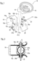
- a steering column arrangement according to the invention is first shown in an isometric exploded view and is generally designated by the reference number 10.
- the steering column arrangement 10 includes a steering column 12 with a substantially circular cross section and an opening 12a running through the entire cross section with a substantially rectangular outline.
- the opening 12a extends both along the longitudinal axis A12 of the steering column 12 and along the circumferential direction thereof.
- a stem 14 is also provided, which carries a steering wheel 16 in a design common for industrial trucks.
- the steering column arrangement 10 comprises a bearing block 18, which is intended to couple the steering column 12 to the vehicle body of the vehicle, not shown, the bearing block 18 consisting of a base plate 18a and two side surfaces 18b and extending from the base plate 18a 18c exists.
- the bearing block 18 consisting of a base plate 18a and two side surfaces 18b and extending from the base plate 18a 18c exists.
- openings 18d and 18e are provided in pairs opposite one another in the two side surfaces 18b and 18c.
- the steering column arrangement 10 comprises a pair of shell elements 20a and 20b, whose outer shape is matched to the inner shape of the two side elements 18b and 18c of the bearing block 18, while their inner shape essentially replicates the circular cross section of the steering column 12.
- a slip-resistant material for example a thermoplastic elastomer.
- a bearing pin 22 is also provided, which in the assembled state consists of Figure 2 both through the opening 12a of the steering column 12 and through the pair of openings 18d in the two side walls 18b and 18c of the bearing block 18.
- a twist clamp 24a or 24b is pushed on, which on the one hand serves to fix the bearing bolt 22 in the position shown together with the head 22a of the bearing bolt 22 or a nut 26 screwed onto it, while between the head 22a and the Clamping lever 28 provided on the torsion clamp 24a or the nut 26 and the torsion clamp 24b with the two Torsional clamps 24a and 24b can interact in such a way that by pressing the clamping lever 28 downwards, the two side walls 18a and 18c of the bearing block are pressed inwards and thus a clamping force is exerted on the steering column 12 via the two shell elements 20a and 20b, which puts it in the corresponding position Position fixed.
- the clamping force acting on the steering column 12 from the side walls 18a and 18b can be reduced to such an extent that it can be displaced relative to the bearing block 18 within a framework specified by the dimensions of the opening 12a and then re-fixed is made possible to adjust the position of the steering wheel 16.
- a rotation of the steering column 12 about its longitudinal axis A12 about the Figure 3 indicated angle ⁇ is possible because the Opening 12a of the steering column 12 has a larger dimension in the circumferential direction than the diameter of the bearing bolt 22 in the area in which it lies in the opening 12a. Due to the fact that the steering wheel 16 is not directly concentric with the circular circumference of the steering column 12, but is spaced from the central longitudinal axis A12 of the steering column, which serves as the axis of rotation, via the stem 14, this rotational movement can thus achieve a displacement of the steering wheel on a circular path around the axis A12, which represents a further degree of freedom for adjusting the position of the steering wheel 16.
- Figure 4 It is also indicated that a rotation of the steering column 12 about the axis A22 defined by the bearing bolts 22 is possible, which enables the steering wheel 14 to be tilted diagonally forward.
- the two shell elements 20a and 20b move together with the steering column 12 within the two side walls 18b and 18c of the bearing block 18, while they remain stationary relative to the bearing block 18 when the steering column 12 is displaced along its longitudinal axis A12 or when the steering column 12 rotates about this axis.
- this steering column arrangement enables the steering wheel 16 to be displaced relative to the bearing block 18 and thus also the vehicle body of the vehicle (not shown) according to three degrees of freedom, which, compared to steering column arrangements known from the prior art, significantly improves ergonomics for the driver of the corresponding vehicle can achieve.
- the fact that the shell elements 20a and 20b, the clamping lever 28, the bearing pin 22 and/or the torsion clamps 24a and 24b can be produced as injection-molded parts results in a significant cost reduction compared to those known from the prior art Steering column arrangements, which were usually manufactured as welded assemblies.
Description
Die vorliegende Erfindung betrifft eine Lenksäulen-Anordnung für ein Fahrzeug, insbesondere ein Flurförderzeug, sowie ein Fahrzeug, insbesondere ein Flurförderzeug, welches eine derartige Lenksäulen-Anordnung umfasst.The present invention relates to a steering column arrangement for a vehicle, in particular an industrial truck, and to a vehicle, in particular an industrial truck, which comprises such a steering column arrangement.
in unterschiedlichen Typen von Fahrzeugen und insbesondere in elektrisch oder verbrennungsmotorisch betriebenen Flurförderzeugen, beispielsweise Gabelstaplern mit elektrischer oder hydraulischer Lenkung, sind bisher Lenksäulen-Anordnungen eingesetzt worden, welche aufwendig aus einer Mehrzahl von Schweißbaugruppen aufgebaut waren. Hierbei lassen sich diese Lenksäulen bezüglich eines Fahrersitzes in der Regel lediglich in ihrer Höhe verstellen oder hinsichtlich ihres Neigungswinkels gegenüber der Vertikalen, um unterschiedlichen Fahrern des entsprechenden Fahrzeugs jeweils eine individuelle Anpassung ihres Arbeitsplatzes zu erlauben.In different types of vehicles and in particular in electrically or internal combustion engine-operated industrial trucks, for example forklifts with electric or hydraulic steering, steering column arrangements have previously been used, which were complexly constructed from a plurality of welded assemblies. These steering columns can generally only be adjusted in height relative to a driver's seat or in terms of their angle of inclination relative to the vertical, in order to allow different drivers of the corresponding vehicle to individually adapt their workplace.
Derartige Lenksäulen-Anordnungen aus dem Stand der Technik sind aufgrund ihres aufwendigen Aufbaus daher jedoch relativ teuer und dadurch, dass sie lediglich um eine horizontal verlaufende Achse neigbar sowie hinsichtlich ihrer Höhe verstellbar sind, auch nicht sonderlich flexibel bei der Anpassung auf individuelle Fahrer solcher Fahrzeuge. Hierbei wirkt sich insbesondere die fehlende Möglichkeit, eine Verstellung der Position des Lenkrads in Querrichtung des Fahrzeugs vorzunehmen, negativ aus, da eine solche Einstellung häufig für eine optimale anatomische Ausrichtung des Lenkrads zu der Fahrerplatzposition wünschenswert wäre.However, such steering column arrangements from the state of the art are relatively expensive due to their complex structure and, because they can only be tilted around a horizontal axis and their height is adjustable, they are not particularly flexible when it comes to adapting to individual drivers of such vehicles. The lack of the option to adjust the position of the steering wheel in the transverse direction of the vehicle has a particularly negative effect, as such an adjustment would often be desirable for an optimal anatomical alignment of the steering wheel to the driver's seat position.
Beispiele für derartige Lenksäulen-Anordnungen sind beispielsweise aus der
Des Weiteren besteht durch die Notwendigkeit des Einsatzes von Teleskoprohren zur Einstellung der Länge der Lenksäule und damit der Höhe des Lenkrads ein erhöhter Wartungsbedarf für die entsprechenden Anordnungen.Furthermore, the need to use telescopic tubes to adjust the length of the steering column and thus the height of the steering wheel means that there is an increased need for maintenance of the corresponding arrangements.
Es ist somit die Aufgabe der vorliegenden Erfindung, eine einfach aufgebaute Lenksäulen-Anordnung bereitzustellen, welche sich neben ihren verringerten Kosten und einem ebenfalls verringerten Wartungsbedarf ferner dadurch auszeichnet, dass eine verbesserte Einstellbarkeit davon vorliegt und damit eine optimale ergonomische Anpassung des Fahrerplatzes auf individuelle Fahrer solcher Fahrzeuge möglich wird.It is therefore the object of the present invention to provide a simply constructed steering column arrangement, which, in addition to its reduced costs and a likewise reduced maintenance requirement, is also characterized by the fact that there is improved adjustability thereof and thus an optimal ergonomic adaptation of the driver's position to individual drivers vehicles becomes possible.
Zu diesem Zweck umfasst die erfindungsgemäße Lenksäulen-Anordnung eine Lenksäule mit einem daran vorgesehenen Lenkrad, welche einen im Wesentlichen kreisförmigen Querschnitt und wenigstens eine durch den gesamten Querschnitt verlaufende Durchbrechung aufweist, einen Lagerbock zur Anbindung der Lenksäule an den Fahrzeugkörper des Fahrzeugs, welcher zwei einander gegenüberliegende Durchbrechungen aufweist, einen Lagerbolzen, welcher in einem montierten Zustand der Lenksäulen-Anordnung durch die Durchbrechungen des Lagerbocks und durch die Durchbrechung der Lenksäule hindurchgeführt und mittels Fixiermitteln festgesetzt ist, und eine Spannvorrichtung, welche dazu eingerichtet und angeordnet ist, in einem angezogenen Zustand eine Klemmkraft durch den Lagerbock auf die Lenksäule hervorzurufen, wobei die Durchbrechung der Lenksäule in Umfangsrichtung davon eine größere Abmessung aufweist als der Durchmesser des Lagerbolzens in dem Bereich, in welchem er in dem montierten Zustand in der Durchbrechung der Lenksäule einliegt.For this purpose, the steering column arrangement according to the invention comprises a steering column with a steering wheel provided thereon, which has a substantially circular cross-section and at least one opening running through the entire cross-section, a bearing block for connecting the steering column to the vehicle body of the vehicle, which has two openings opposite one another, a bearing bolt which, in an assembled state of the steering column arrangement, is guided through the openings of the bearing block and through the opening of the steering column and is fixed by means of fixing means, and a clamping device which is designed and arranged to cause a clamping force through the bearing block on the steering column in a tightened state, wherein the opening of the steering column has a larger dimension in the circumferential direction thereof than the diameter of the bearing bolt in the area in which it lies in the opening of the steering column in the assembled state.
Durch die Merkmale der erfindungsgemäßen Lenksäulen-Anordnung kann eine Verdrehbarkeit der Lenksäule gegenüber dem Lagerbock um ihre Längsachse gemäß der Abmessungen der Durchbrechung da hindurch erzielt werden. Da in einer Weiterbildung der Erfindung an der Oberseite der Lenksäule ferner ein Vorbau vorgesehen sein kann, welcher das Lenkrad in einer von einer Längsachse der Lenksäule versetzten Weise trägt, kann somit durch eine derartige Verdrehung eine Verlagerung des Lenkrads auf einer kreisförmigen Bahn um die genannte Längsachse herum erzielt werden, was einen zusätzlichen Freiheitsgrad für die Einstellung der Position des Lenkrads darstellt. Allerdings kann die vorliegende Erfindung auch in Ausführungsformen eingesetzt werden, in welchen das Lenkrad konzentrisch mit der Lenksäule angeordnet ist, sofern durch die Verdrehung davon andere ergonomische Vorteile erzielt werden können, beispielsweise weitere mit der Lenksäule gekoppelte Anbaukomponenten an geeignetere Positionen verschwenkt werden können.Due to the features of the steering column arrangement according to the invention, the steering column can be rotated relative to the bearing block about its longitudinal axis according to the dimensions of the opening therethrough. achieved. Since, in a further development of the invention, a stem can also be provided on the upper side of the steering column, which supports the steering wheel in a manner offset from a longitudinal axis of the steering column, a displacement of the steering wheel on a circular path around said longitudinal axis can thus be achieved by such a rotation, which represents an additional degree of freedom for adjusting the position of the steering wheel. However, the present invention can also be used in embodiments in which the steering wheel is arranged concentrically with the steering column, provided that other ergonomic advantages can be achieved by the rotation thereof, for example other add-on components coupled to the steering column can be pivoted to more suitable positions.
Ferner ist der Aufbau der erfindungsgemäßen Lenksäulen-Anordnung gegenüber den oben beschriebenen Vorrichtungen aus dem Stand der Technik deutlich vereinfacht, sodass eine Kostenreduzierung und ein verringerter Wartungsaufwand erzielt werden kann. Indem ferner in einer Weiterbildung die Durchbrechung der Lenksäule in Längsrichtung davon eine größere Abmessung aufweist als der Durchmesser des Lagerbolzens in dem Bereich, in welchem er in montiertem Zustand in der Durchbrechung der Lenksäule einliegt, kann ferner eine Verlagerbarkeit der Lenksäule und damit des Lenkrads entlang ihrer Längsachse erzielt werden.Furthermore, the structure of the steering column arrangement according to the invention is significantly simplified compared to the prior art devices described above, so that a cost reduction and reduced maintenance effort can be achieved. Furthermore, in a further development, the opening in the steering column has a larger dimension in the longitudinal direction than the diameter of the bearing bolt in the area in which it rests in the opening in the steering column in the assembled state, the steering column and thus the steering wheel can also be moved along it Longitudinal axis can be achieved.
Hierbei versteht es sich, dass die Durchbrechung der Lenksäule nicht im strengen Wortsinne als Langloch aufgefasst werden kann, da sie eine Verstellung der Lenksäule gemäß zwei Freiheitsgraden erlaubt, zum einen entlang ihrer Längsachse und zum anderen eine Rotation um ihre Lenkachse herum. Jedoch kann auf bei Langlöchern übliche Ausgestaltungen zurückgegriffen werden, beispielsweise kann eine Krümmung davon entlang seiner Erstreckung vorgesehen sein, insbesondere in Längsrichtung der Lenksäule. Des Weiteren versteht es sich, dass in einer Variante davon auch wenigstens zwei derartige Durchbrechungen in der Lenksäule vorgesehen sein könnten, welche dann zunächst einmal eine grobe Einstellung ihrer Position entlang ihrer Längsachse oder ihres Winkels um die Längsachse ermöglichen würden und anschließend eine feinere Einstellung des entsprechenden Freiheitsgrads. Hierdurch kann auf übermäßig große Durchbrechungen verzichtet werden, die unter Umständen die mechanische Festigkeit der Lenksäule beeinträchtigen könnten, während jedoch trotzdem ein großer Einstellungsbereich der Position des Lenkrads bewerkstelligt werden kann.It is understood that the opening in the steering column cannot be understood as an elongated hole in the strict sense of the word, since it allows adjustment of the steering column according to two degrees of freedom, firstly along its longitudinal axis and secondly rotation around its steering axis. However, it is possible to use designs that are usual for elongated holes, for example a curvature can be provided along its extension, in particular in the longitudinal direction of the steering column. Furthermore, it is understood that in a variant thereof at least two such openings can also be provided in the steering column. which would then first allow a rough adjustment of its position along its longitudinal axis or its angle around the longitudinal axis and then a finer adjustment of the corresponding degree of freedom. This makes it possible to avoid excessively large openings which could potentially compromise the mechanical strength of the steering column, while still allowing a large range of adjustment of the position of the steering wheel.
Weiterhin kann die erfindungsgemäße Lenksäulen-Anordnung ein Paar von Schalenelementen umfassen, welche in montiertem Zustand der Lenksäulen-Anordnung zwischen dem Lagerbock und der Lenksäule vorgesehen sind, wobei ihre Innenform im Wesentlichen der Querschnittsform der Lenksäule entspricht. In einer solchen Ausführungsform wirkt die Klemmkraft der Spannvorrichtung dann indirekt von dem Lagerbock über die Schalenelemente auf die Lenksäule. Alternativ könnte selbstverständlich auch die Innenform des Lagerbocks dementsprechend ausgebildet sein, die Lenksäule direkt zu führen, dies würde jedoch unter Umständen ein Montieren der erfindungsgemäßen Anordnung erschweren, da dann ein Einlegen der Lenksäule in den Lagerbock an ihre letztendliche Position lediglich noch entlang ihrer Längsachse möglich wäre, während durch den Einsatz der Schalenelemente der Lagerbock derart gestaltet werden kann, dass die aus den Schalenelementen und der Lenksäule gebildete Baugruppe als Ganzes auch von einer Seite her in den Lagerbock einführbar ist.Furthermore, the steering column arrangement according to the invention can comprise a pair of shell elements, which are provided between the bearing block and the steering column in the assembled state of the steering column arrangement, their internal shape essentially corresponding to the cross-sectional shape of the steering column. In such an embodiment, the clamping force of the clamping device then acts indirectly from the bearing block via the shell elements on the steering column. Alternatively, the internal shape of the bearing block could of course also be designed to guide the steering column directly, but this would possibly make it more difficult to assemble the arrangement according to the invention, since inserting the steering column into the bearing block in its final position would then only be possible along its longitudinal axis , while by using the shell elements, the bearing block can be designed in such a way that the assembly formed from the shell elements and the steering column as a whole can also be inserted into the bearing block from one side.
Hierbei können die Schalenelemente dann insbesondere an ihrer Innenseite und/oder an ihrer Außenseite mit einem rutschhemmenden Material versehen sein, um die Übertragung der Klemmkraft zu befördern und ein Abgleiten der entsprechenden Komponente zu verhindern, wobei insbesondere ein thermoplastisches Elastomer zum Einsatz kommen kann.In this case, the shell elements can then be provided with an anti-slip material, in particular on their inner side and/or on their outer side, in order to promote the transmission of the clamping force and to prevent the corresponding component from slipping, whereby in particular a thermoplastic elastomer can be used.
Ein weiterer Freiheitsgrad zur Einstellung der Position des Lenkrads wird erzielt, indem der Lagerbock und/oder die Schalenelemente derart ausgebildet sind, dass in einem gelösten Zustand der Spannvorrichtung eine Rotation der Lenksäule um den Lagerbolzen ermöglicht ist. Somit sind dann jeweilige Rotationen der Lenksäule um zwei im Wesentlichen orthogonal zueinander orientierte Raumachsen möglich, sodass im Fall des zusätzlichen Vorsehens der Möglichkeit einer Verlagerbarkeit der Lenksäule entlang ihrer Längsachse eine praktisch unbegrenzte Einstellung der Position des Lenkrads im Raum möglich ist.A further degree of freedom for adjusting the position of the steering wheel is achieved by designing the bearing block and/or the shell elements in such a way that, when the clamping device is in a released state, rotation of the steering column about the bearing pin is possible. This means that respective rotations of the steering column about two spatial axes that are essentially orthogonal to one another are possible, so that in the event of additional provision for the possibility of displaceability of the steering column along its longitudinal axis, a practically unlimited adjustment of the position of the steering wheel in space is possible.
In einer besonders einfach zu bedienenden Ausführungsform kann die Spannvorrichtung einen Klemmhebel umfassen, welcher es einem Bediener ermöglicht, eine ausreichend hohe Klemmkraft auf den Lagerbock auszuüben, um eine sichere Fixierung der Lenksäule und damit des Lenkrads in der gewünschten Ausrichtung hervorzurufen. Andererseits könnten selbstverständlich auch andere Spannvorrichtungen zum Einsatz kommen, beispielsweise unter dem Einsatz von Verschraubungen oder Ähnlichem.In a particularly easy-to-use embodiment, the clamping device can comprise a clamping lever, which enables an operator to exert a sufficiently high clamping force on the bearing block in order to securely fix the steering column and thus the steering wheel in the desired orientation. On the other hand, other clamping devices could of course also be used, for example using screw connections or similar.
Indem die Fixiermittel des Lagerbolzens als an beiden Enden davon anbringbare Verdrehspanner ausgebildet sind, welche dazu eingerichtet sind, mit dem eben beschriebenen Klemmhebel der Spannvorrichtung zusammenzuwirken, kann ferner die Funktion dieser beiden Komponenten der erfindungsgemäßen Anordnung kombiniert werden, sodass eine besonders einfache und kompakt aufgebaute Fixierung des Lagerbolzens sowie Verklemmung der Lenksäule in dem Lagerbock erzielt wird.Because the fixing means of the bearing bolt are designed as torsion clamps that can be attached to both ends and are designed to interact with the clamping lever of the clamping device just described, the function of these two components of the arrangement according to the invention can also be combined, so that a particularly simple and compact fixation of the bearing pin and jamming of the steering column in the bearing block.
Erfindungsgemäß kann ferner wenigstens eines aus den Schalenelementen, dem Klemmhebel, dem Lagerbolzen und/oder der Verdrehspanner als Spritzgussteil gebildet sein, sodass hier eine erhebliche Kostenersparnis gegenüber den oben beschriebenen Schweißbaugruppen aus dem Stand der Technik erzielt werden kann.According to the invention, at least one of the shell elements, the clamping lever, the bearing bolt and/or the torsion clamp can be formed as an injection-molded part, so that a considerable cost saving can be achieved compared to the above-described welded assemblies from the prior art.
Wie bereits weiter oben ebenfalls angedeutet, betrifft die vorliegende Erfindung weiterhin ein Fahrzeug, insbesondere ein Flurförderzeug, umfassend eine Lenksäulen-Anordnung nach einem der vorhergehenden Ansprüche.As already indicated above, the present invention further relates to a vehicle, in particular an industrial truck, comprising a steering column arrangement according to one of the preceding claims.
Weitere Merkmale und Vorteile der vorliegenden Erfindung werden aus der nachfolgenden Beschreibung einer Ausführungsform davon deutlich, wenn diese gemeinsam mit den beiliegenden Figuren betrachtet wird. Diese zeigen im Einzelnen:
- Fig. 1
- eine erfindungsgemäße Lenksäulen-Anordnung in einer isometrischen Explosionsansicht;
- Fig. 2
- die Anordnung aus
Figur 1 in einem montierten Zustand in isometrischer Ansicht; - Fig. 3
- eine Querschnittsansicht der Anordnung aus
Figur 2 im Bereich des Lagerbocks; und - Fig. 4
- eine schematische Detailansicht der Lenksäule im Bereich ihrer Durchbrechung.
- Fig. 1
- a steering column arrangement according to the invention in an isometric exploded view;
- Fig. 2
- the arrangement
Figure 1 in an assembled state in an isometric view; - Fig. 3
- a cross-sectional view of the arrangement
Figure 2 in the area of the bearing block; and - Fig. 4
- a schematic detailed view of the steering column in the area of its opening.
In
Des Weiteren umfasst die Lenksäulen-Anordnung 10 einen Lagerbock 18, welcher dazu vorgesehen ist, die Lenksäule 12 mit dem Fahrzeugkörper des nicht weiter dargestellten Fahrzeugs zu koppeln, wobei der Lagerbock 18 aus einer Grundplatte 18a und zwei sich von der Grundplatte 18a erstreckenden Seitenflächen 18b und 18c besteht. Hierbei sind in den beiden Seitenflächen 18b und 18c einander gegenüberliegend paarweise Durchbrechungen 18d und 18e vorgesehen.Furthermore, the
Weiterhin umfasst die Lenksäulen-Anordnung 10 ein Paar von Schalenelementen 20a und 20b, welche in ihrer Außenform auf die Innenform der beiden Seitenelemente 18b und 18c des Lagerbocks 18 abgestimmt sind, während ihre Innenform im Wesentlichen den kreisförmigen Querschnitt der Lenksäule 12 nachbildet. Um ein unerwünschtes Abgleiten der Schalenelemente 20a und 20b an dem Lagerbock 18 oder der Lenksäule 12 zu verhindern, können diese jeweils an ihrer Innenseite und/oder an ihrer Außenseite mit einem rutschhemmenden Material versehen sein, beispielsweise einem thermoplastischen Elastomer.Furthermore, the
Zusätzlich unter Verweis auf die
Hierbei ist an den beiden Enden des Lagerbolzens 22 in dem in
Lediglich der Vollständigkeit halber sei ferner noch auf die beiden Schrauben-Mutter-Kombinationen 30 verwiesen, welche in dem montierten Zustand aus
In der
Des Weiteren ist jedoch ebenfalls eine Rotation der Lenksäule 12 um ihre Längsachse A12 um den in
Zuletzt ist in
Somit wird durch die erfindungsgemäße Ausgestaltung dieser Lenksäulen-Anordnung eine Verlagerung des Lenkrads 16 gegenüber dem Lagerbock 18 und damit auch dem Fahrzeugkörper des nicht dargestellten Fahrzeugs gemäß dreier Freiheitsgrade ermöglicht, was im Vergleich zu aus dem Stand der Technik bekannten Lenksäulenanordnungen eine wesentlich verbesserte Ergonomie für den Fahrer des entsprechenden Fahrzeugs erzielen kann. Indem ferner die Schalenelemente 20a und 20b, der Klemmhebel 28, der Lagerbolzen 22 und/oder die Verdrehspanner 24a und 24b als Spritzgussteile hergestellt werden können, stellt sich ferner eine deutliche Kostenreduzierung gegenüber aus dem Stand der Technik bekannten Lenksäulen-Anordnungen ein, die in der Regel als Schweißbaugruppen gefertigt waren.Thus, the inventive design of this steering column arrangement enables the
Claims (9)
- Steering column assembly (10) for a vehicle, in particular an industrial truck, comprising:- a steering column (12) having a steering wheel (16) provided thereon, which column has a substantially circular cross section and at least one aperture (12a) extending through the entire cross section;- a bearing block (18) for connecting the steering column (12) to the vehicle body of the vehicle, which bearing block comprises two apertures (18d) which are opposite one another;- a bearing bolt (22) which, in a mounted state of the steering column assembly (10), is guided through the apertures (18) of the bearing block and the aperture (12a) of the steering column (12) and is fixed by fixing means (24a, 24b); and- a clamping device (24a, 24b, 26, 28) which is designed and arranged, in a tightened state, to bring about a clamping force on the steering column (12) by means of the bearing block (18);the aperture (12a) of the steering column (12) having a larger dimension in the peripheral direction thereof than the diameter of the bearing bolt (22) in the region in which it rests in the aperture (12a) of the steering column (12) in the mounted state,characterised in that the bearing block (18) and/or the shell elements (20a, 20b) are designed in such a way that a rotation of the steering column (12) about the bearing bolt (22) is made possible in a released state of the clamping device (24a, 24b, 26, 28).
- Steering column assembly (10) according to claim 1, wherein a stem (14) is furthermore provided on the upper side of the steering column (12), which stem carries the steering wheel (16) in a manner offset from a longitudinal axis (A12) of the steering column (12).
- Steering column assembly (10) according to either claim 1 or claim 2,
wherein the aperture (12a) of the steering column (12) has a larger dimension in the longitudinal direction (A12) thereof than the diameter of the bearing bolt (22) in the region in which it rests in the aperture (12a) of the steering column (12) in the mounted state. - Steering column assembly (10) according to any of the preceding claims,
further comprising a pair of shell elements (20a, 20b) which, in the mounted state of the steering column assembly (10), are provided between the bearing block (18) and the steering column (12), wherein the internal shape of said shell elements substantially corresponds to the cross-sectional shape of the steering column (12). - Steering column assembly (10) according to claim 4,
wherein the shell elements (20a, 20b) are provided on their inside and/or on their outside with an anti-slip material, for example a thermoplastic elastomer. - Steering column assembly (10) according to any of the preceding claims, wherein the clamping device (24a, 24b, 26, 28) comprises a clamping lever (28).
- Steering column assembly (10) according to claim 6,
wherein the fixing means (24a, 24b) of the bearing bolt (22) is designed as torque wrenches (24a, 24b) which can be applied to both ends of said bearing bolt and which are designed to interact with the clamping lever (28) of the clamping device. - Steering column assembly (10) according to any of the preceding claims,
wherein the shell elements (20a, 20b), the clamping lever (28), the bearing bolt (22), and/or the torque wrenches (24a, 24b) is/are formed as injection-moulded parts. - Vehicle, in particular industrial truck, comprising a steering column assembly (10) according to any of the preceding claims.
Applications Claiming Priority (1)
| Application Number | Priority Date | Filing Date | Title |
|---|---|---|---|
| DE102021100785.2A DE102021100785A1 (en) | 2021-01-15 | 2021-01-15 | STEERING COLUMN ARRANGEMENT FOR A VEHICLE |
Publications (2)
| Publication Number | Publication Date |
|---|---|
| EP4029760A1 EP4029760A1 (en) | 2022-07-20 |
| EP4029760B1 true EP4029760B1 (en) | 2024-04-03 |
Family
ID=79601592
Family Applications (1)
| Application Number | Title | Priority Date | Filing Date |
|---|---|---|---|
| EP22151304.7A Active EP4029760B1 (en) | 2021-01-15 | 2022-01-13 | Steering column assembly for a vehicle |
Country Status (3)
| Country | Link |
|---|---|
| EP (1) | EP4029760B1 (en) |
| CN (1) | CN114763174A (en) |
| DE (1) | DE102021100785A1 (en) |
Citations (2)
| Publication number | Priority date | Publication date | Assignee | Title |
|---|---|---|---|---|
| JP2003341527A (en) * | 2002-05-27 | 2003-12-03 | Nsk Ltd | Steering device for vehicle, and manufacturing method |
| DE10260523A1 (en) * | 2002-12-21 | 2004-07-01 | Volkswagen Ag | Adjustable safety steering column for automobile with upper and lower setting devices for telescopic steering shaft housing at ends of steering block |
Family Cites Families (6)
| Publication number | Priority date | Publication date | Assignee | Title |
|---|---|---|---|---|
| DE10160303B4 (en) | 2001-12-07 | 2010-04-15 | Linde Material Handling Gmbh | Steering device for a self-propelled work machine |
| JP5472216B2 (en) * | 2010-07-06 | 2014-04-16 | 日本精工株式会社 | Steering device |
| JP6192565B2 (en) * | 2014-02-21 | 2017-09-06 | 富士機工株式会社 | Steering column device |
| EP3025929B1 (en) * | 2014-11-28 | 2017-06-14 | Aktiebolaget SKF | User interface actuator for a pilot-by-wire system |
| GB201517828D0 (en) * | 2015-10-08 | 2015-11-25 | Trw Ltd And Trw Steering Systems Poland Sp Z O O | A lever for a steering column assembly |
| IT201700121893A1 (en) * | 2017-10-26 | 2019-04-26 | Ferrari Spa | "STEER BY WIRE" ROAD VEHICLE SYSTEM AND PROVIDED WITH A MECHANICAL STEERING WHEEL STROKE DEVICE " |
-
2021
- 2021-01-15 DE DE102021100785.2A patent/DE102021100785A1/en active Pending
-
2022
- 2022-01-12 CN CN202210039673.2A patent/CN114763174A/en active Pending
- 2022-01-13 EP EP22151304.7A patent/EP4029760B1/en active Active
Patent Citations (2)
| Publication number | Priority date | Publication date | Assignee | Title |
|---|---|---|---|---|
| JP2003341527A (en) * | 2002-05-27 | 2003-12-03 | Nsk Ltd | Steering device for vehicle, and manufacturing method |
| DE10260523A1 (en) * | 2002-12-21 | 2004-07-01 | Volkswagen Ag | Adjustable safety steering column for automobile with upper and lower setting devices for telescopic steering shaft housing at ends of steering block |
Also Published As
| Publication number | Publication date |
|---|---|
| EP4029760A1 (en) | 2022-07-20 |
| DE102021100785A1 (en) | 2022-07-21 |
| CN114763174A (en) | 2022-07-19 |
Similar Documents
| Publication | Publication Date | Title |
|---|---|---|
| EP1671527B1 (en) | Connecting element | |
| DE3138083A1 (en) | "ADJUSTABLE SUPPORT FOR STEERING COLUMN" | |
| EP3475146A1 (en) | Ball screw drive of an electromechanical power steering device with deflecting bodies for a ball return | |
| DE19934739B4 (en) | Steering device for a vehicle | |
| DE10013726A1 (en) | Flap hinge | |
| DE102012101388A1 (en) | Steering shaft for a motor vehicle | |
| WO2003104035A1 (en) | Height-adjustable loading base for a motor vehicle | |
| DE1555465B1 (en) | Adjustable steering column for motor vehicles | |
| EP1513717B1 (en) | Securing device for locking an adjustable connecting part | |
| DE102007048208B4 (en) | Steering column for a motor vehicle | |
| DE102012101386A1 (en) | Steering column for a motor vehicle | |
| DE102016206564A1 (en) | Actuator with a spindle drive | |
| DE1405837C3 (en) | Arrangement for attaching a counterweight to a lift truck | |
| DE10141551A1 (en) | Steering column for vehicles has safety feature with rip mechanism mounted between bearing part and lever part of clamping lever which is used to fix the steering column | |
| EP4029760B1 (en) | Steering column assembly for a vehicle | |
| EP1382509B1 (en) | Steering column | |
| EP1901953B1 (en) | Clamping device for a steering column | |
| EP1223001A2 (en) | Device for the precise positioning of a workpiece, in particular of a vehicle body part | |
| DE60303527T2 (en) | coupling arrangement | |
| DE3100701A1 (en) | Eccentric adjustment for the coupling ring of a steering rod in wheel suspensions in motor vehicles | |
| EP3911553B1 (en) | Steering column for a motor vehicle | |
| DE19748117A1 (en) | Ball-ended spindle for vehicle ball-and-socket joint | |
| DE4231497C2 (en) | Steering arrangement for motor vehicles | |
| EP3573851B1 (en) | Fork for articulation and actuator with a fork for an articulation | |
| EP3334636B1 (en) | Clamping device for an adjustable steering column for a motor vehicle |
Legal Events
| Date | Code | Title | Description |
|---|---|---|---|
| PUAI | Public reference made under article 153(3) epc to a published international application that has entered the european phase |
Free format text: ORIGINAL CODE: 0009012 |
|
| STAA | Information on the status of an ep patent application or granted ep patent |
Free format text: STATUS: THE APPLICATION HAS BEEN PUBLISHED |
|
| AK | Designated contracting states |
Kind code of ref document: A1 Designated state(s): AL AT BE BG CH CY CZ DE DK EE ES FI FR GB GR HR HU IE IS IT LI LT LU LV MC MK MT NL NO PL PT RO RS SE SI SK SM TR |
|
| STAA | Information on the status of an ep patent application or granted ep patent |
Free format text: STATUS: REQUEST FOR EXAMINATION WAS MADE |
|
| 17P | Request for examination filed |
Effective date: 20220818 |
|
| RBV | Designated contracting states (corrected) |
Designated state(s): AL AT BE BG CH CY CZ DE DK EE ES FI FR GB GR HR HU IE IS IT LI LT LU LV MC MK MT NL NO PL PT RO RS SE SI SK SM TR |
|
| P01 | Opt-out of the competence of the unified patent court (upc) registered |
Effective date: 20230628 |
|
| GRAP | Despatch of communication of intention to grant a patent |
Free format text: ORIGINAL CODE: EPIDOSNIGR1 |
|
| STAA | Information on the status of an ep patent application or granted ep patent |
Free format text: STATUS: GRANT OF PATENT IS INTENDED |
|
| INTG | Intention to grant announced |
Effective date: 20231020 |
|
| GRAS | Grant fee paid |
Free format text: ORIGINAL CODE: EPIDOSNIGR3 |
|
| GRAA | (expected) grant |
Free format text: ORIGINAL CODE: 0009210 |
|
| STAA | Information on the status of an ep patent application or granted ep patent |
Free format text: STATUS: THE PATENT HAS BEEN GRANTED |
|
| AK | Designated contracting states |
Kind code of ref document: B1 Designated state(s): AL AT BE BG CH CY CZ DE DK EE ES FI FR GB GR HR HU IE IS IT LI LT LU LV MC MK MT NL NO PL PT RO RS SE SI SK SM TR |