EP4029709A1 - Parking fuel oil air heater with two brushless electric motor combustion heads - Google Patents
Parking fuel oil air heater with two brushless electric motor combustion heads Download PDFInfo
- Publication number
- EP4029709A1 EP4029709A1 EP21735565.0A EP21735565A EP4029709A1 EP 4029709 A1 EP4029709 A1 EP 4029709A1 EP 21735565 A EP21735565 A EP 21735565A EP 4029709 A1 EP4029709 A1 EP 4029709A1
- Authority
- EP
- European Patent Office
- Prior art keywords
- combustion
- wind wheel
- fuel
- supporting
- air
- Prior art date
- Legal status (The legal status is an assumption and is not a legal conclusion. Google has not performed a legal analysis and makes no representation as to the accuracy of the status listed.)
- Granted
Links
- 238000002485 combustion reaction Methods 0.000 title claims abstract description 43
- 239000000295 fuel oil Substances 0.000 title 1
- 239000000446 fuel Substances 0.000 claims abstract description 64
- 230000009977 dual effect Effects 0.000 claims abstract description 19
- XAGFODPZIPBFFR-UHFFFAOYSA-N aluminium Chemical compound [Al] XAGFODPZIPBFFR-UHFFFAOYSA-N 0.000 claims abstract description 13
- 229910052782 aluminium Inorganic materials 0.000 claims abstract description 13
- 238000013016 damping Methods 0.000 claims description 7
- 239000007789 gas Substances 0.000 claims description 7
- 238000007789 sealing Methods 0.000 claims description 7
- QVGXLLKOCUKJST-UHFFFAOYSA-N atomic oxygen Chemical compound [O] QVGXLLKOCUKJST-UHFFFAOYSA-N 0.000 claims description 4
- 239000001301 oxygen Substances 0.000 claims description 4
- 229910052760 oxygen Inorganic materials 0.000 claims description 4
- 238000010438 heat treatment Methods 0.000 description 4
- 230000000694 effects Effects 0.000 description 2
- 238000009825 accumulation Methods 0.000 description 1
- 238000010586 diagram Methods 0.000 description 1
- 239000010763 heavy fuel oil Substances 0.000 description 1
- 230000004048 modification Effects 0.000 description 1
- 238000012986 modification Methods 0.000 description 1
Images
Classifications
-
- B—PERFORMING OPERATIONS; TRANSPORTING
- B60—VEHICLES IN GENERAL
- B60H—ARRANGEMENTS OF HEATING, COOLING, VENTILATING OR OTHER AIR-TREATING DEVICES SPECIALLY ADAPTED FOR PASSENGER OR GOODS SPACES OF VEHICLES
- B60H1/00—Heating, cooling or ventilating [HVAC] devices
- B60H1/22—Heating, cooling or ventilating [HVAC] devices the heat being derived otherwise than from the propulsion plant
- B60H1/2203—Heating, cooling or ventilating [HVAC] devices the heat being derived otherwise than from the propulsion plant the heat being derived from burners
- B60H1/2212—Heating, cooling or ventilating [HVAC] devices the heat being derived otherwise than from the propulsion plant the heat being derived from burners arrangements of burners for heating air
-
- B—PERFORMING OPERATIONS; TRANSPORTING
- B60—VEHICLES IN GENERAL
- B60H—ARRANGEMENTS OF HEATING, COOLING, VENTILATING OR OTHER AIR-TREATING DEVICES SPECIALLY ADAPTED FOR PASSENGER OR GOODS SPACES OF VEHICLES
- B60H1/00—Heating, cooling or ventilating [HVAC] devices
- B60H1/22—Heating, cooling or ventilating [HVAC] devices the heat being derived otherwise than from the propulsion plant
- B60H2001/2268—Constructional features
- B60H2001/2278—Connectors, water supply, housing, mounting brackets
-
- B—PERFORMING OPERATIONS; TRANSPORTING
- B60—VEHICLES IN GENERAL
- B60H—ARRANGEMENTS OF HEATING, COOLING, VENTILATING OR OTHER AIR-TREATING DEVICES SPECIALLY ADAPTED FOR PASSENGER OR GOODS SPACES OF VEHICLES
- B60H1/00—Heating, cooling or ventilating [HVAC] devices
- B60H1/22—Heating, cooling or ventilating [HVAC] devices the heat being derived otherwise than from the propulsion plant
- B60H2001/2268—Constructional features
- B60H2001/2281—Air supply, exhaust systems
-
- F—MECHANICAL ENGINEERING; LIGHTING; HEATING; WEAPONS; BLASTING
- F24—HEATING; RANGES; VENTILATING
- F24H—FLUID HEATERS, e.g. WATER OR AIR HEATERS, HAVING HEAT-GENERATING MEANS, e.g. HEAT PUMPS, IN GENERAL
- F24H3/00—Air heaters
- F24H3/02—Air heaters with forced circulation
- F24H3/06—Air heaters with forced circulation the air being kept separate from the heating medium, e.g. using forced circulation of air over radiators
Definitions
- This application relates to the technical field of air heaters, in particular to a dual brushless motor combustion head parking fuel air heater.
- the combustion head of the parking fuel air heater generally adopts one motor, and a shaft is protruded from each of the two ends of the motor, so as to drive the combustion-supporting wind wheel and the hot wind wheel to rotate synchronously. Too high or too low speed of the combustion-supporting wind wheel will cause the fire to be blown off in strong wind or insufficient oxygen combustion in low wind, so the rotating speed of the hot wind wheel cannot be increased at will to increase the air volume since it is limited by the rotating speed of the combustion-supporting wind wheel.
- the internal heat of the heater needs to be considered for the air volume of the hot wind wheel when the heater changes from high to low, and if the rotating speed of the hot wind wheel drops too fast, the internal heat of the heater cannot be blown out in time, which will cause heat accumulation, so the downshift time of the combustion-supporting wind wheel is longer since it is limited by the hot wind wheel.
- the combustion-supporting wind wheel supports combustion at low speed to consume residual fuel, so that the hot air wind wheel can not cool the machine at high speed and high air volume, resulting in a long shutdown delay.
- the two wind wheels restrict each other's speed, the hot air channel connected with the air heater on the market has tended to be a multibranch and multi-outlet integrated air duct, which replaces the original shorter hot air duct arrangement, and the air volume of the hot wind wheel driven by a single motor is limited by the combustion-supporting wind wheel, so that the heating requirements of the integrated air duct can no longer meet, the air volume of the outlet at the far end of the integrated air duct is weak and the heating effect is not good.
- this application provides a dual brushless motor combustion head parking fuel air heater, which can solve the above problems.
- a dual brushless motor combustion head parking fuel air heater including a housing assembly, an air inlet connected to the housing assembly and an air outlet connected to the housing assembly.
- a heat exchanger is provided at an end of the housing assembly close to the air outlet.
- a heat exchange channel is arranged between the heat exchanger and the housing assembly, and the heat exchange channel is respectively communicated with the air inlet and the air outlet.
- a hot wind wheel motor is provided at the air inlet, and the hot wind wheel motor is connected with a hot wind wheel.
- the heat exchanger is connected with an aluminum bracket, and a combustion-supporting wind wheel motor and a combustion-supporting air inlet are provided in the aluminum bracket.
- An output shaft of the combustion-supporting wind wheel motor is configured to penetrate through the aluminum bracket and connect with a combustion-supporting wind wheel, and the combustion-supporting air inlet is located at one side close to the combustion-supporting wind wheel.
- a combustion chamber assembly is provided inside the heat exchanger, the combustion chamber assembly and the combustion-supporting wind wheel are located on a same straight line, and an ignition plug assembly and a fuel inlet are provided inside the combustion chamber assembly.
- a controller is provided on an outside of the housing assembly, and the controller is respectively electrically connected with the hot wind wheel motor, the combustion-supporting wind wheel motor and the ignition plug assembly.
- a first temperature sensor is provided on an outer side wall of the heat exchanger, and the first temperature sensor is electrically connected to the controller.
- a second temperature sensor is provided at the air inlet, and the second temperature sensor is electrically connected to the controller.
- the fuel inlet is connected with a fuel volatilization net.
- a sealing damping pad is provided on an outer side wall of the housing assembly, the heat exchanger defines an exhaust gas outlet, and the combustion-supporting air inlet, the exhaust gas outlet and the fuel inlet are configured to extend to the sealing damping pad.
- controller is configured to control rotating speeds of the hot wind wheel and the combustion-supporting wind wheel respectively to reduce downshift time and shutdown delay time.
- the combustion-supporting wind wheel motor is configured to drive the combustion-supporting wind wheel to rotate when a whole machine is ignited, so that oxygen enters from the combustion-supporting air inlet and then enters the combustion chamber assembly.
- the combustion chamber assembly is configured to transport fuel to the fuel volatilization net through the fuel inlet and form atomized fuel with the combustion-supporting wind wheel.
- the ignition plug assembly is configured for ignition and configured to flameout when a preset temperature difference is detected by the first temperature sensor.
- the controller is configured to control gradual increase of fuel supply and combustion-supporting air volume.
- the heat exchanger is configured to diffuse heat into the heat exchange channel and the hot wind wheel is configured to carry out the heat.
- the controller is further configured to control reduction of the fuel volume and the combustion-supporting air volume, at the same time control increase of a power of the hot wind wheel motor, and control the hot wind wheel to carry out the heat when an actual inlet air temperature detected by the second temperature sensor is higher than a preset inlet air temperature.
- the controller is further configured to control fuel cut-off, cease-fire and alarm, control the combustion-supporting wind wheel to gradually slow down and stop, and control the hot wind wheel to increase the rotating speed when a temperature detected by the first temperature sensor is higher than a preset alarm temperature.
- controller is further configured to control cut-off of fuel passage of the fuel inlet, at the same time control the combustion-supporting wind wheel to gradually slow down and stop, control the ignition plug assembly to ignite to clean up remaining fuel, and control the hot wind wheel to increase the rotating speed to carry out heat to reduce shutdown delay when shutting down.
- This application is provided with a heat exchanger, a hot wind wheel motor, a hot wind wheel, a combustion-supporting wind wheel motor, a combustion-supporting wind wheel, a combustion chamber assembly, a first temperature sensor and a second temperature sensor, which solves the problem of long downshift time and shutdown delay time by controlling the rotating speeds of the hot wind wheel and the combustion-supporting wind wheel respectively, and meets the heating requirements of the integrated air duct, thereby the heating effect is improved.
- a dual brushless motor combustion head parking fuel air heater including a housing assembly 1, an air inlet 2 connected to the housing assembly 1 and an air outlet 3 connected to the housing assembly 1.
- a heat exchanger 4 is provided at an end of the housing assembly 1 close to the air outlet 3.
- a heat exchange channel is arranged between the heat exchanger 4 and the housing assembly 1, and the heat exchange channel is respectively communicated with the air inlet 2 and the air outlet 3.
- a hot wind wheel motor 5 is provided at the air inlet 2, and the hot wind wheel motor 5 is connected with a hot wind wheel 6.
- the heat exchanger 4 is connected with an aluminum bracket 7, and a combustion-supporting wind wheel motor 8 and a combustion-supporting air inlet 9 are provided in the aluminum bracket 7.
- An output shaft of the combustion-supporting wind wheel motor 8 is configured to penetrate through the aluminum bracket 7 and connect with a combustion-supporting wind wheel 10, and the combustion-supporting air inlet 9 is located at one side close to the combustion-supporting wind wheel 10.
- a combustion chamber assembly 11 is provided inside the heat exchanger 4, the combustion chamber assembly 11 and the combustion-supporting wind wheel 10 are located on a same straight line, and an ignition plug assembly 12 and a fuel inlet 13 are provided inside the combustion chamber assembly 11.
- a controller 15 is provided on an outside of the housing assembly 1, and the controller 15 is respectively electrically connected with the hot wind wheel motor 5, the combustion-supporting wind wheel motor 8 and the ignition plug assembly 12.
- a first temperature sensor 16 is provided on an outer side wall of the heat exchanger 4, and the first temperature sensor 16 is electrically connected to the controller 15.
- a second temperature sensor 17 is provided at the air inlet 2, and the second temperature sensor 17 is electrically connected to the controller 15.
- the fuel inlet 13 is connected with a fuel volatilization net.
- a sealing damping pad 18 is provided on an outer side wall of the housing assembly 1, the heat exchanger 4 defines an exhaust gas outlet 14, and the combustion-supporting air inlet 9, the exhaust gas outlet 14 and the fuel inlet 13 are configured to extend to the sealing damping pad 18.
- the combustion-supporting wind wheel motor 8 drives the combustion-supporting wind wheel 10 to rotate when a whole machine is ignited, so that oxygen enters from the combustion-supporting air inlet 9 and then enters the combustion chamber assembly 11.
- Fuel is transported to the fuel volatilization net through the fuel inlet 13 in the combustion chamber assembly 11 to form atomized fuel with the combustion-supporting wind wheel 10.
- the ignition plug assembly 12 ignites, and then flames out when a preset temperature difference is detected by the first temperature sensor 16.
- the controller 15 controls gradual increase of fuel supply and combustion-supporting air volume.
- the heat exchanger 4 diffuses heat into the heat exchange channel, and finally the heat is carried out by the hot wind wheel 6.
- the controller 15 controls reduction of the fuel volume and the combustion-supporting air volume, at the same time controls increase of a power of the hot wind wheel motor 5, and controls the hot wind wheel 6 to carry out the heat when an actual inlet air temperature detected by the second temperature sensor 17 is higher than a preset inlet air temperature.
- the controller 15 controls fuel cut-off, cease-fire and alarm, controls the combustion-supporting wind wheel 10 to gradually slow down and stop, and controls the hot wind wheel 6 to increase the rotating speed when a temperature detected by the first temperature sensor 16 is higher than a preset alarm temperature.
- the controller 15 controls cut-off of fuel passage of the fuel inlet 13, at the same time controls the combustion-supporting wind wheel 10 to gradually slow down and stop, controls the ignition plug assembly 12 to ignite to clean up remaining fuel, and controls the hot wind wheel 6 to increase the rotating speed to carry out heat to reduce shutdown delay when shutting down.
Abstract
Description
- This application claims the priority of
Chinese Patent Application No. 202011351660.6, filed on November 27, 2020 Chinese Patent Application No. 202022794726.0, filed on November 27, 2020 - This application relates to the technical field of air heaters, in particular to a dual brushless motor combustion head parking fuel air heater.
- At present, the combustion head of the parking fuel air heater generally adopts one motor, and a shaft is protruded from each of the two ends of the motor, so as to drive the combustion-supporting wind wheel and the hot wind wheel to rotate synchronously. Too high or too low speed of the combustion-supporting wind wheel will cause the fire to be blown off in strong wind or insufficient oxygen combustion in low wind, so the rotating speed of the hot wind wheel cannot be increased at will to increase the air volume since it is limited by the rotating speed of the combustion-supporting wind wheel. The internal heat of the heater needs to be considered for the air volume of the hot wind wheel when the heater changes from high to low, and if the rotating speed of the hot wind wheel drops too fast, the internal heat of the heater cannot be blown out in time, which will cause heat accumulation, so the downshift time of the combustion-supporting wind wheel is longer since it is limited by the hot wind wheel. When it is necessary to shut down the machine, the combustion-supporting wind wheel supports combustion at low speed to consume residual fuel, so that the hot air wind wheel can not cool the machine at high speed and high air volume, resulting in a long shutdown delay. The two wind wheels restrict each other's speed, the hot air channel connected with the air heater on the market has tended to be a multibranch and multi-outlet integrated air duct, which replaces the original shorter hot air duct arrangement, and the air volume of the hot wind wheel driven by a single motor is limited by the combustion-supporting wind wheel, so that the heating requirements of the integrated air duct can no longer meet, the air volume of the outlet at the far end of the integrated air duct is weak and the heating effect is not good.
- In view of the problems in related arts, no effective solutions have been proposed.
- In view of the above technical problems in the related art, this application provides a dual brushless motor combustion head parking fuel air heater, which can solve the above problems.
- In order to achieve the above technical purpose, the technical scheme of this application is realized as follows:
A dual brushless motor combustion head parking fuel air heater, including a housing assembly, an air inlet connected to the housing assembly and an air outlet connected to the housing assembly. A heat exchanger is provided at an end of the housing assembly close to the air outlet. A heat exchange channel is arranged between the heat exchanger and the housing assembly, and the heat exchange channel is respectively communicated with the air inlet and the air outlet. A hot wind wheel motor is provided at the air inlet, and the hot wind wheel motor is connected with a hot wind wheel. The heat exchanger is connected with an aluminum bracket, and a combustion-supporting wind wheel motor and a combustion-supporting air inlet are provided in the aluminum bracket. An output shaft of the combustion-supporting wind wheel motor is configured to penetrate through the aluminum bracket and connect with a combustion-supporting wind wheel, and the combustion-supporting air inlet is located at one side close to the combustion-supporting wind wheel. A combustion chamber assembly is provided inside the heat exchanger, the combustion chamber assembly and the combustion-supporting wind wheel are located on a same straight line, and an ignition plug assembly and a fuel inlet are provided inside the combustion chamber assembly. A controller is provided on an outside of the housing assembly, and the controller is respectively electrically connected with the hot wind wheel motor, the combustion-supporting wind wheel motor and the ignition plug assembly. - Further, a first temperature sensor is provided on an outer side wall of the heat exchanger, and the first temperature sensor is electrically connected to the controller.
- Further, a second temperature sensor is provided at the air inlet, and the second temperature sensor is electrically connected to the controller.
- Further, the fuel inlet is connected with a fuel volatilization net.
- Further, a sealing damping pad is provided on an outer side wall of the housing assembly, the heat exchanger defines an exhaust gas outlet, and the combustion-supporting air inlet, the exhaust gas outlet and the fuel inlet are configured to extend to the sealing damping pad.
- Further, the controller is configured to control rotating speeds of the hot wind wheel and the combustion-supporting wind wheel respectively to reduce downshift time and shutdown delay time.
- Further, the combustion-supporting wind wheel motor is configured to drive the combustion-supporting wind wheel to rotate when a whole machine is ignited, so that oxygen enters from the combustion-supporting air inlet and then enters the combustion chamber assembly. The combustion chamber assembly is configured to transport fuel to the fuel volatilization net through the fuel inlet and form atomized fuel with the combustion-supporting wind wheel. The ignition plug assembly is configured for ignition and configured to flameout when a preset temperature difference is detected by the first temperature sensor. The controller is configured to control gradual increase of fuel supply and combustion-supporting air volume. The heat exchanger is configured to diffuse heat into the heat exchange channel and the hot wind wheel is configured to carry out the heat. The controller is further configured to control reduction of the fuel volume and the combustion-supporting air volume, at the same time control increase of a power of the hot wind wheel motor, and control the hot wind wheel to carry out the heat when an actual inlet air temperature detected by the second temperature sensor is higher than a preset inlet air temperature. The controller is further configured to control fuel cut-off, cease-fire and alarm, control the combustion-supporting wind wheel to gradually slow down and stop, and control the hot wind wheel to increase the rotating speed when a temperature detected by the first temperature sensor is higher than a preset alarm temperature.
- Further, the controller is further configured to control cut-off of fuel passage of the fuel inlet, at the same time control the combustion-supporting wind wheel to gradually slow down and stop, control the ignition plug assembly to ignite to clean up remaining fuel, and control the hot wind wheel to increase the rotating speed to carry out heat to reduce shutdown delay when shutting down.
- This application is provided with a heat exchanger, a hot wind wheel motor, a hot wind wheel, a combustion-supporting wind wheel motor, a combustion-supporting wind wheel, a combustion chamber assembly, a first temperature sensor and a second temperature sensor, which solves the problem of long downshift time and shutdown delay time by controlling the rotating speeds of the hot wind wheel and the combustion-supporting wind wheel respectively, and meets the heating requirements of the integrated air duct, thereby the heating effect is improved.
- In order to more clearly explain the embodiments of this application or the technical solutions in the art, the drawings used in the description of the embodiments will be briefly introduced below. Obviously, the drawings in the following description are merely some embodiments of this application. For those of ordinary skill in the art, other drawings can be obtained based on these drawings without paying creative work.
-
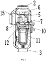
FIG. 1 is a cross-sectional view of a dual brushless motor combustion head parking fuel air heater according to an embodiment of this application. -
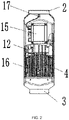
FIG. 2 is a partial cross-sectional view of the dual brushless motor combustion head parking fuel air heater according to an embodiment of this application. -
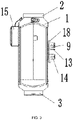
FIG. 3 is an outline structure diagram of the dual brushless motor combustion head parking fuel air heater according to an embodiment of this application. - In the drawings: 1. Housing assembly, 2. Air inlet, 3. Air outlet, 4. Heat exchanger, 5. Hot wind wheel motor, 6. Hot wind wheel, 7. Aluminum bracket, 8. Combustion-supporting wind wheel motor, 9. Combustion-supporting air inlet, 10. Combustion-supporting wind wheel, 11. Combustion chamber assembly, 12. Ignition plug assembly, 13. Fuel inlet, 14. Exhaust gas outlet, 15. Controller, 16. First temperature sensor, 17. Second temperature sensor, and 18. Sealing damping pad.
- In the following, the technical solutions in the embodiments of this application will be clearly and completely described in connection with the drawings in the embodiments of this application. Obviously, the described embodiments are only a part of the embodiments of this application, but not all of the embodiments. Based on the embodiments of this application, all other embodiments obtained by those of ordinary skill in the art shall fall within the claimed scope of this application.
- As shown in
FIGS. 1 to 3 , a dual brushless motor combustion head parking fuel air heater, including ahousing assembly 1, anair inlet 2 connected to thehousing assembly 1 and anair outlet 3 connected to thehousing assembly 1. Aheat exchanger 4 is provided at an end of thehousing assembly 1 close to theair outlet 3. A heat exchange channel is arranged between theheat exchanger 4 and thehousing assembly 1, and the heat exchange channel is respectively communicated with theair inlet 2 and theair outlet 3. A hotwind wheel motor 5 is provided at theair inlet 2, and the hotwind wheel motor 5 is connected with ahot wind wheel 6. Theheat exchanger 4 is connected with analuminum bracket 7, and a combustion-supportingwind wheel motor 8 and a combustion-supportingair inlet 9 are provided in thealuminum bracket 7. An output shaft of the combustion-supportingwind wheel motor 8 is configured to penetrate through thealuminum bracket 7 and connect with a combustion-supportingwind wheel 10, and the combustion-supportingair inlet 9 is located at one side close to the combustion-supportingwind wheel 10. Acombustion chamber assembly 11 is provided inside theheat exchanger 4, thecombustion chamber assembly 11 and the combustion-supportingwind wheel 10 are located on a same straight line, and anignition plug assembly 12 and afuel inlet 13 are provided inside thecombustion chamber assembly 11. Acontroller 15 is provided on an outside of thehousing assembly 1, and thecontroller 15 is respectively electrically connected with the hotwind wheel motor 5, the combustion-supportingwind wheel motor 8 and theignition plug assembly 12. - In a specific embodiment of this application, a
first temperature sensor 16 is provided on an outer side wall of theheat exchanger 4, and thefirst temperature sensor 16 is electrically connected to thecontroller 15. - In a specific embodiment of this application, a
second temperature sensor 17 is provided at theair inlet 2, and thesecond temperature sensor 17 is electrically connected to thecontroller 15. - In a specific embodiment of this application, the
fuel inlet 13 is connected with a fuel volatilization net. - In a specific embodiment of this application, a sealing damping
pad 18 is provided on an outer side wall of thehousing assembly 1, theheat exchanger 4 defines anexhaust gas outlet 14, and the combustion-supportingair inlet 9, theexhaust gas outlet 14 and thefuel inlet 13 are configured to extend to the sealing dampingpad 18. - In order to facilitate the understanding of the above-mentioned technical solutions of this application, the above-mentioned technical solutions of this application are described in detail below through specific usage modes.
- In specific use, according to the dual brushless motor combustion head parking fuel air heater of this application, the combustion-supporting
wind wheel motor 8 drives the combustion-supportingwind wheel 10 to rotate when a whole machine is ignited, so that oxygen enters from the combustion-supportingair inlet 9 and then enters thecombustion chamber assembly 11. Fuel is transported to the fuel volatilization net through thefuel inlet 13 in thecombustion chamber assembly 11 to form atomized fuel with the combustion-supportingwind wheel 10. At the same time, theignition plug assembly 12 ignites, and then flames out when a preset temperature difference is detected by thefirst temperature sensor 16. Thecontroller 15 controls gradual increase of fuel supply and combustion-supporting air volume. Theheat exchanger 4 diffuses heat into the heat exchange channel, and finally the heat is carried out by thehot wind wheel 6. Thecontroller 15 controls reduction of the fuel volume and the combustion-supporting air volume, at the same time controls increase of a power of the hotwind wheel motor 5, and controls thehot wind wheel 6 to carry out the heat when an actual inlet air temperature detected by thesecond temperature sensor 17 is higher than a preset inlet air temperature. Thecontroller 15 controls fuel cut-off, cease-fire and alarm, controls the combustion-supportingwind wheel 10 to gradually slow down and stop, and controls thehot wind wheel 6 to increase the rotating speed when a temperature detected by thefirst temperature sensor 16 is higher than a preset alarm temperature. Thecontroller 15 controls cut-off of fuel passage of thefuel inlet 13, at the same time controls the combustion-supportingwind wheel 10 to gradually slow down and stop, controls theignition plug assembly 12 to ignite to clean up remaining fuel, and controls thehot wind wheel 6 to increase the rotating speed to carry out heat to reduce shutdown delay when shutting down. - The above are only preferred embodiments of this application and are not used to limit this application. Any modification, equivalent replacement, improvement, etc. made within the spirit and principle of this application shall be included in the scope of this application.
Claims (8)
- A dual brushless motor combustion head parking fuel air heater, comprising a housing assembly (1), an air inlet (2) connected to the housing assembly (1) and an air outlet (3) connected to the housing assembly (1), wherein a heat exchanger (4) is provided at an end of the housing assembly (1) close to the air outlet (3), a heat exchange channel is arranged between the heat exchanger (4) and the housing assembly (1), the heat exchange channel is respectively communicated with the air inlet (2) and the air outlet (3), a hot wind wheel motor (5) is provided at the air inlet (2), the hot wind wheel motor (5) is connected with a hot wind wheel (6), the heat exchanger (4) is connected with an aluminum bracket (7), a combustion-supporting wind wheel motor (8) and a combustion-supporting air inlet (9) are provided in the aluminum bracket (7), an output shaft of the combustion-supporting wind wheel motor (8) is configured to penetrate through the aluminum bracket (7) and connect with a combustion-supporting wind wheel (10), the combustion-supporting air inlet (9) is located at one side close to the combustion-supporting wind wheel (10), a combustion chamber assembly (11) is provided inside the heat exchanger (4), the combustion chamber assembly (11) and the combustion-supporting wind wheel (10) are located on a same straight line, an ignition plug assembly (12) and a fuel inlet (13) are provided inside the combustion chamber assembly (11), a controller (15) is provided on an outside of the housing assembly (1), and the controller (15) is respectively electrically connected with the hot wind wheel motor (5), the combustion-supporting wind wheel motor (8) and the ignition plug assembly (12).
- The dual brushless motor combustion head parking fuel air heater of claim 1, wherein a first temperature sensor (16) is provided on an outer side wall of the heat exchanger (4), and the first temperature sensor (16) is electrically connected to the controller (15).
- The dual brushless motor combustion head parking fuel air heater of claim 1, wherein a second temperature sensor (17) is provided at the air inlet (2), and the second temperature sensor (17) is electrically connected to the controller (15).
- The dual brushless motor combustion head parking fuel air heater of claim 1, wherein the fuel inlet (13) is connected with a fuel volatilization net.
- The dual brushless motor combustion head parking fuel air heater of claim 1, wherein a sealing damping pad (18) is provided on an outer side wall of the housing assembly (1), the heat exchanger (4) defines an exhaust gas outlet (14), and the combustion-supporting air inlet (9), the exhaust gas outlet (14) and the fuel inlet (13) are configured to extend to the sealing damping pad (18).
- The dual brushless motor combustion head parking fuel air heater of claim 1, wherein the controller is configured to control rotating speeds of the hot wind wheel (6) and the combustion-supporting wind wheel (10) respectively to reduce downshift time and shutdown delay time.
- The dual brushless motor combustion head parking fuel air heater of claim 4, wherein the combustion-supporting wind wheel motor (8) is configured to drive the combustion-supporting wind wheel (10) to rotate when a whole machine is ignited, so that oxygen enters from the combustion-supporting air inlet (9) and then enters the combustion chamber assembly (11), the combustion chamber assembly (11) is configured to transport fuel to the fuel volatilization net through the fuel inlet (13) and form atomized fuel with the combustion-supporting wind wheel (10), the ignition plug assembly (12) is configured for ignition and configured to flameout when a preset temperature difference is detected by the first temperature sensor (16), the controller (15) is configured to control gradual increase of fuel supply and combustion-supporting air volume, the heat exchanger (4) is configured to diffuse heat into the heat exchange channel and the hot wind wheel (6) is configured to carry out the heat, the controller (15) is further configured to control reduction of the fuel volume and the combustion-supporting air volume, at the same time control increase of a power of the hot wind wheel motor (5), and control the hot wind wheel (6) to carry out the heat when an actual inlet air temperature detected by the second temperature sensor (17) is higher than a preset inlet air temperature, and the controller (15) is further configured to control fuel cut-off, cease-fire and alarm, control the combustion-supporting wind wheel (10) to gradually slow down and stop, and control the hot wind wheel (6) to increase the rotating speed when a temperature detected by the first temperature sensor (16) is higher than a preset alarm temperature.
- The dual brushless motor combustion head parking fuel air heater of claim 7, wherein the controller (15) is further configured to control cut-off of fuel passage of the fuel inlet (13), at the same time control the combustion-supporting wind wheel (10) to gradually slow down and stop, control the ignition plug assembly (12) to ignite to clean up remaining fuel, and control the hot wind wheel (6) to increase the rotating speed to carry out heat to reduce shutdown delay when shutting down.
Applications Claiming Priority (3)
| Application Number | Priority Date | Filing Date | Title |
|---|---|---|---|
| CN202011351660.6A CN112389164A (en) | 2020-11-27 | 2020-11-27 | Parking fuel air heater with double brushless motor combustion heads |
| CN202022794726.0U CN213892111U (en) | 2020-11-27 | 2020-11-27 | Parking fuel air heater with double brushless motor combustion heads |
| PCT/CN2021/100474 WO2022110772A1 (en) | 2020-11-27 | 2021-06-17 | Parking fuel oil air heater with two brushless electric motor combustion heads |
Publications (4)
| Publication Number | Publication Date |
|---|---|
| EP4029709A1 true EP4029709A1 (en) | 2022-07-20 |
| EP4029709A4 EP4029709A4 (en) | 2022-12-14 |
| EP4029709B1 EP4029709B1 (en) | 2024-01-03 |
| EP4029709C0 EP4029709C0 (en) | 2024-01-03 |
Family
ID=81603521
Family Applications (1)
| Application Number | Title | Priority Date | Filing Date |
|---|---|---|---|
| EP21735565.0A Active EP4029709B1 (en) | 2020-11-27 | 2021-06-17 | Parking fuel oil air heater with two brushless electric motor combustion heads |
Country Status (2)
| Country | Link |
|---|---|
| EP (1) | EP4029709B1 (en) |
| WO (1) | WO2022110772A1 (en) |
Families Citing this family (1)
| Publication number | Priority date | Publication date | Assignee | Title |
|---|---|---|---|---|
| CN115059567B (en) * | 2022-08-18 | 2024-01-16 | 哈尔滨尚迪天科技发展有限公司 | Parking fuel heater device based on bluetooth control |
Family Cites Families (15)
| Publication number | Priority date | Publication date | Assignee | Title |
|---|---|---|---|---|
| DE1130572B (en) * | 1951-10-31 | 1962-05-30 | Eberspaecher J | Safety device on air heaters fired with liquid fuel, especially for heating small spaces, e.g. B. in motor vehicles |
| US2779398A (en) * | 1953-06-05 | 1957-01-29 | Hupp Corp | Forced draft liquid fuel burner of the retort type, and heating apparatus incorporating the same |
| DE19652970C2 (en) * | 1996-12-19 | 1999-12-16 | Eberspaecher J Gmbh & Co | Air heater operated with liquid fuel, in particular air heater for motor vehicles |
| DE10002217B4 (en) * | 2000-01-20 | 2005-05-25 | J. Eberspächer GmbH & Co. KG | Method for determining the temperature of a vehicle interior |
| DE10063922C1 (en) * | 2000-12-20 | 2002-07-18 | Webasto Thermosysteme Gmbh | Heater, for vehicle, includes protective device with heat carrier mass flow meter to protect immediately against overheating |
| CN201851254U (en) * | 2010-10-19 | 2011-06-01 | 河北南风汽车设备集团有限公司 | Centrifugal air fuel heater |
| KR101209932B1 (en) * | 2010-10-29 | 2012-12-10 | 기아자동차주식회사 | A combustion type gas heater for vehicles |
| DE102014210005A1 (en) * | 2014-05-26 | 2015-11-26 | Eberspächer Climate Control Systems GmbH & Co. KG | Air heater, in particular for vehicles |
| CN206092222U (en) * | 2016-10-18 | 2017-04-12 | 陈刚 | Variable heating capacity fuel oil heater |
| CN206678737U (en) * | 2017-05-05 | 2017-11-28 | 吉林省德沃尔机电有限公司 | The vehicle-mounted fuel heater of intelligent frequency-conversion dual control |
| CN106985634B (en) * | 2017-05-05 | 2023-09-05 | 吉林省德沃尔机电有限公司 | Intelligent variable-frequency double-control vehicle-mounted fuel heater and control method thereof |
| CN207010453U (en) * | 2017-05-05 | 2018-02-13 | 吉林省德沃尔机电有限公司 | A kind of same axle position dual-output motor device |
| DE102017125783B4 (en) * | 2017-11-06 | 2019-09-05 | Eberspächer Climate Control Systems GmbH & Co. KG | vehicle heater |
| DK180206B1 (en) * | 2018-06-05 | 2020-08-17 | Entiffic Aps | Portable heating system |
| CN112389164A (en) * | 2020-11-27 | 2021-02-23 | 京威汽车设备有限公司 | Parking fuel air heater with double brushless motor combustion heads |
-
2021
- 2021-06-17 EP EP21735565.0A patent/EP4029709B1/en active Active
- 2021-06-17 WO PCT/CN2021/100474 patent/WO2022110772A1/en unknown
Also Published As
| Publication number | Publication date |
|---|---|
| EP4029709B1 (en) | 2024-01-03 |
| WO2022110772A1 (en) | 2022-06-02 |
| EP4029709C0 (en) | 2024-01-03 |
| EP4029709A4 (en) | 2022-12-14 |
Similar Documents
| Publication | Publication Date | Title |
|---|---|---|
| CN102538174B (en) | Low-noise gas instantaneous water heater | |
| CN2842210Y (en) | High-efficiency heat-exchange full-premixing burning system | |
| EP4029709A1 (en) | Parking fuel oil air heater with two brushless electric motor combustion heads | |
| CN201851254U (en) | Centrifugal air fuel heater | |
| CN201000168Y (en) | Environmental protection constant temp gas water heater | |
| CN201851258U (en) | Centrifugal liquid fuel oil heater | |
| CN206092222U (en) | Variable heating capacity fuel oil heater | |
| CN112389164A (en) | Parking fuel air heater with double brushless motor combustion heads | |
| US4138986A (en) | High efficiency furnace with low polluting emissions | |
| CN213892111U (en) | Parking fuel air heater with double brushless motor combustion heads | |
| CN210568427U (en) | Self-suction automatic self-adjusting air mixing auxiliary device | |
| CN207835366U (en) | A kind of warm wind thermo-electric generation all-in-one machine | |
| CN209165381U (en) | A kind of combustion chamber box structure | |
| CN202303445U (en) | Intelligent fuel gas equipment control system | |
| CN202532690U (en) | Low-noise gas rapid water heater | |
| CN207881197U (en) | Gas heater | |
| JP3686486B2 (en) | Original mixed gas combustion equipment | |
| CN202040808U (en) | Helical flame burner | |
| CN109026492A (en) | A kind of cold start-up of engineering machinery and heating system | |
| CN217520053U (en) | Novel gas wall-mounted furnace | |
| CN218062442U (en) | Low-power liquid fuel heater | |
| CN215336295U (en) | Air quantity adjusting device of combustor | |
| CN203518215U (en) | Oil-fired fan heater | |
| CN112428786A (en) | New energy automobile room heater | |
| CN110966765A (en) | Control method of supercharged gas water heater and gas water heater |
Legal Events
| Date | Code | Title | Description |
|---|---|---|---|
| STAA | Information on the status of an ep patent application or granted ep patent |
Free format text: STATUS: UNKNOWN |
|
| STAA | Information on the status of an ep patent application or granted ep patent |
Free format text: STATUS: THE INTERNATIONAL PUBLICATION HAS BEEN MADE |
|
| PUAI | Public reference made under article 153(3) epc to a published international application that has entered the european phase |
Free format text: ORIGINAL CODE: 0009012 |
|
| STAA | Information on the status of an ep patent application or granted ep patent |
Free format text: STATUS: REQUEST FOR EXAMINATION WAS MADE |
|
| 17P | Request for examination filed |
Effective date: 20210708 |
|
| AK | Designated contracting states |
Kind code of ref document: A1 Designated state(s): AL AT BE BG CH CY CZ DE DK EE ES FI FR GB GR HR HU IE IS IT LI LT LU LV MC MK MT NL NO PL PT RO RS SE SI SK SM TR |
|
| A4 | Supplementary search report drawn up and despatched |
Effective date: 20221111 |
|
| RIC1 | Information provided on ipc code assigned before grant |
Ipc: F24H 3/06 20220101ALI20221107BHEP Ipc: F02N 19/02 20100101ALI20221107BHEP Ipc: B60H 1/22 20060101AFI20221107BHEP |
|
| STAA | Information on the status of an ep patent application or granted ep patent |
Free format text: STATUS: EXAMINATION IS IN PROGRESS |
|
| 17Q | First examination report despatched |
Effective date: 20230525 |
|
| GRAP | Despatch of communication of intention to grant a patent |
Free format text: ORIGINAL CODE: EPIDOSNIGR1 |
|
| STAA | Information on the status of an ep patent application or granted ep patent |
Free format text: STATUS: GRANT OF PATENT IS INTENDED |
|
| DAV | Request for validation of the european patent (deleted) | ||
| DAX | Request for extension of the european patent (deleted) | ||
| INTG | Intention to grant announced |
Effective date: 20231002 |
|
| GRAS | Grant fee paid |
Free format text: ORIGINAL CODE: EPIDOSNIGR3 |
|
| GRAA | (expected) grant |
Free format text: ORIGINAL CODE: 0009210 |
|
| STAA | Information on the status of an ep patent application or granted ep patent |
Free format text: STATUS: THE PATENT HAS BEEN GRANTED |
|
| AK | Designated contracting states |
Kind code of ref document: B1 Designated state(s): AL AT BE BG CH CY CZ DE DK EE ES FI FR GB GR HR HU IE IS IT LI LT LU LV MC MK MT NL NO PL PT RO RS SE SI SK SM TR |
|
| REG | Reference to a national code |
Ref country code: GB Ref legal event code: FG4D |
|
| REG | Reference to a national code |
Ref country code: DE Ref legal event code: R096 Ref document number: 602021008378 Country of ref document: DE |
|
| REG | Reference to a national code |
Ref country code: CH Ref legal event code: EP |
|
| REG | Reference to a national code |
Ref country code: IE Ref legal event code: FG4D |
|
| U01 | Request for unitary effect filed |
Effective date: 20240105 |
|
| U07 | Unitary effect registered |
Designated state(s): AT BE BG DE DK EE FI FR IT LT LU LV MT NL PT SE SI Effective date: 20240116 |