EP4029678A1 - Autoklavsystem, blasenanordnung und zugehöriges verfahren zur herstellung eines teils - Google Patents
Autoklavsystem, blasenanordnung und zugehöriges verfahren zur herstellung eines teils Download PDFInfo
- Publication number
- EP4029678A1 EP4029678A1 EP21217350.4A EP21217350A EP4029678A1 EP 4029678 A1 EP4029678 A1 EP 4029678A1 EP 21217350 A EP21217350 A EP 21217350A EP 4029678 A1 EP4029678 A1 EP 4029678A1
- Authority
- EP
- European Patent Office
- Prior art keywords
- bladder
- interior
- end portion
- pressure
- fluid flow
- Prior art date
- Legal status (The legal status is an assumption and is not a legal conclusion. Google has not performed a legal analysis and makes no representation as to the accuracy of the status listed.)
- Pending
Links
Images


Classifications
-
- B—PERFORMING OPERATIONS; TRANSPORTING
- B29—WORKING OF PLASTICS; WORKING OF SUBSTANCES IN A PLASTIC STATE IN GENERAL
- B29C—SHAPING OR JOINING OF PLASTICS; SHAPING OF MATERIAL IN A PLASTIC STATE, NOT OTHERWISE PROVIDED FOR; AFTER-TREATMENT OF THE SHAPED PRODUCTS, e.g. REPAIRING
- B29C70/00—Shaping composites, i.e. plastics material comprising reinforcements, fillers or preformed parts, e.g. inserts
- B29C70/04—Shaping composites, i.e. plastics material comprising reinforcements, fillers or preformed parts, e.g. inserts comprising reinforcements only, e.g. self-reinforcing plastics
- B29C70/28—Shaping operations therefor
- B29C70/40—Shaping or impregnating by compression not applied
- B29C70/42—Shaping or impregnating by compression not applied for producing articles of definite length, i.e. discrete articles
- B29C70/44—Shaping or impregnating by compression not applied for producing articles of definite length, i.e. discrete articles using isostatic pressure, e.g. pressure difference-moulding, vacuum bag-moulding, autoclave-moulding or expanding rubber-moulding
- B29C70/446—Moulding structures having an axis of symmetry or at least one channel, e.g. tubular structures, frames
-
- B—PERFORMING OPERATIONS; TRANSPORTING
- B29—WORKING OF PLASTICS; WORKING OF SUBSTANCES IN A PLASTIC STATE IN GENERAL
- B29C—SHAPING OR JOINING OF PLASTICS; SHAPING OF MATERIAL IN A PLASTIC STATE, NOT OTHERWISE PROVIDED FOR; AFTER-TREATMENT OF THE SHAPED PRODUCTS, e.g. REPAIRING
- B29C70/00—Shaping composites, i.e. plastics material comprising reinforcements, fillers or preformed parts, e.g. inserts
- B29C70/04—Shaping composites, i.e. plastics material comprising reinforcements, fillers or preformed parts, e.g. inserts comprising reinforcements only, e.g. self-reinforcing plastics
- B29C70/28—Shaping operations therefor
- B29C70/40—Shaping or impregnating by compression not applied
- B29C70/42—Shaping or impregnating by compression not applied for producing articles of definite length, i.e. discrete articles
- B29C70/44—Shaping or impregnating by compression not applied for producing articles of definite length, i.e. discrete articles using isostatic pressure, e.g. pressure difference-moulding, vacuum bag-moulding, autoclave-moulding or expanding rubber-moulding
-
- B—PERFORMING OPERATIONS; TRANSPORTING
- B29—WORKING OF PLASTICS; WORKING OF SUBSTANCES IN A PLASTIC STATE IN GENERAL
- B29C—SHAPING OR JOINING OF PLASTICS; SHAPING OF MATERIAL IN A PLASTIC STATE, NOT OTHERWISE PROVIDED FOR; AFTER-TREATMENT OF THE SHAPED PRODUCTS, e.g. REPAIRING
- B29C33/00—Moulds or cores; Details thereof or accessories therefor
- B29C33/44—Moulds or cores; Details thereof or accessories therefor with means for, or specially constructed to facilitate, the removal of articles, e.g. of undercut articles
- B29C33/48—Moulds or cores; Details thereof or accessories therefor with means for, or specially constructed to facilitate, the removal of articles, e.g. of undercut articles with means for collapsing or disassembling
- B29C33/50—Moulds or cores; Details thereof or accessories therefor with means for, or specially constructed to facilitate, the removal of articles, e.g. of undercut articles with means for collapsing or disassembling elastic or flexible
- B29C33/505—Moulds or cores; Details thereof or accessories therefor with means for, or specially constructed to facilitate, the removal of articles, e.g. of undercut articles with means for collapsing or disassembling elastic or flexible cores or mandrels, e.g. inflatable
-
- B—PERFORMING OPERATIONS; TRANSPORTING
- B29—WORKING OF PLASTICS; WORKING OF SUBSTANCES IN A PLASTIC STATE IN GENERAL
- B29C—SHAPING OR JOINING OF PLASTICS; SHAPING OF MATERIAL IN A PLASTIC STATE, NOT OTHERWISE PROVIDED FOR; AFTER-TREATMENT OF THE SHAPED PRODUCTS, e.g. REPAIRING
- B29C35/00—Heating, cooling or curing, e.g. crosslinking or vulcanising; Apparatus therefor
- B29C35/02—Heating or curing, e.g. crosslinking or vulcanizing during moulding, e.g. in a mould
- B29C35/0227—Heating or curing, e.g. crosslinking or vulcanizing during moulding, e.g. in a mould using pressure vessels, e.g. autoclaves, vulcanising pans
-
- B—PERFORMING OPERATIONS; TRANSPORTING
- B29—WORKING OF PLASTICS; WORKING OF SUBSTANCES IN A PLASTIC STATE IN GENERAL
- B29C—SHAPING OR JOINING OF PLASTICS; SHAPING OF MATERIAL IN A PLASTIC STATE, NOT OTHERWISE PROVIDED FOR; AFTER-TREATMENT OF THE SHAPED PRODUCTS, e.g. REPAIRING
- B29C70/00—Shaping composites, i.e. plastics material comprising reinforcements, fillers or preformed parts, e.g. inserts
- B29C70/04—Shaping composites, i.e. plastics material comprising reinforcements, fillers or preformed parts, e.g. inserts comprising reinforcements only, e.g. self-reinforcing plastics
- B29C70/28—Shaping operations therefor
- B29C70/54—Component parts, details or accessories; Auxiliary operations, e.g. feeding or storage of prepregs or SMC after impregnation or during ageing
-
- B—PERFORMING OPERATIONS; TRANSPORTING
- B29—WORKING OF PLASTICS; WORKING OF SUBSTANCES IN A PLASTIC STATE IN GENERAL
- B29D—PRODUCING PARTICULAR ARTICLES FROM PLASTICS OR FROM SUBSTANCES IN A PLASTIC STATE
- B29D99/00—Subject matter not provided for in other groups of this subclass
- B29D99/001—Producing wall or panel-like structures, e.g. for hulls, fuselages, or buildings
- B29D99/0014—Producing wall or panel-like structures, e.g. for hulls, fuselages, or buildings provided with ridges or ribs, e.g. joined ribs
-
- B—PERFORMING OPERATIONS; TRANSPORTING
- B29—WORKING OF PLASTICS; WORKING OF SUBSTANCES IN A PLASTIC STATE IN GENERAL
- B29C—SHAPING OR JOINING OF PLASTICS; SHAPING OF MATERIAL IN A PLASTIC STATE, NOT OTHERWISE PROVIDED FOR; AFTER-TREATMENT OF THE SHAPED PRODUCTS, e.g. REPAIRING
- B29C43/00—Compression moulding, i.e. applying external pressure to flow the moulding material; Apparatus therefor
- B29C43/32—Component parts, details or accessories; Auxiliary operations
- B29C43/36—Moulds for making articles of definite length, i.e. discrete articles
- B29C43/3642—Bags, bleeder sheets or cauls for isostatic pressing
- B29C2043/3649—Inflatable bladders using gas or fluid and related details
-
- B—PERFORMING OPERATIONS; TRANSPORTING
- B29—WORKING OF PLASTICS; WORKING OF SUBSTANCES IN A PLASTIC STATE IN GENERAL
- B29K—INDEXING SCHEME ASSOCIATED WITH SUBCLASSES B29B, B29C OR B29D, RELATING TO MOULDING MATERIALS OR TO MATERIALS FOR MOULDS, REINFORCEMENTS, FILLERS OR PREFORMED PARTS, e.g. INSERTS
- B29K2063/00—Use of EP, i.e. epoxy resins or derivatives thereof, as moulding material
-
- B—PERFORMING OPERATIONS; TRANSPORTING
- B29—WORKING OF PLASTICS; WORKING OF SUBSTANCES IN A PLASTIC STATE IN GENERAL
- B29K—INDEXING SCHEME ASSOCIATED WITH SUBCLASSES B29B, B29C OR B29D, RELATING TO MOULDING MATERIALS OR TO MATERIALS FOR MOULDS, REINFORCEMENTS, FILLERS OR PREFORMED PARTS, e.g. INSERTS
- B29K2307/00—Use of elements other than metals as reinforcement
- B29K2307/04—Carbon
-
- B—PERFORMING OPERATIONS; TRANSPORTING
- B29—WORKING OF PLASTICS; WORKING OF SUBSTANCES IN A PLASTIC STATE IN GENERAL
- B29K—INDEXING SCHEME ASSOCIATED WITH SUBCLASSES B29B, B29C OR B29D, RELATING TO MOULDING MATERIALS OR TO MATERIALS FOR MOULDS, REINFORCEMENTS, FILLERS OR PREFORMED PARTS, e.g. INSERTS
- B29K2309/00—Use of inorganic materials not provided for in groups B29K2303/00 - B29K2307/00, as reinforcement
- B29K2309/08—Glass
-
- B—PERFORMING OPERATIONS; TRANSPORTING
- B29—WORKING OF PLASTICS; WORKING OF SUBSTANCES IN A PLASTIC STATE IN GENERAL
- B29L—INDEXING SCHEME ASSOCIATED WITH SUBCLASS B29C, RELATING TO PARTICULAR ARTICLES
- B29L2031/00—Other particular articles
- B29L2031/30—Vehicles, e.g. ships or aircraft, or body parts thereof
- B29L2031/3076—Aircrafts
Definitions
- This disclosure relates generally to forming composite parts, and more particularly to forming composite parts using an autoclave and a flexible bladder.
- Autoclaves provide the heat and pressure necessary to cure composite parts made of curable materials, such as fiber-reinforced polymer materials including catalyzing resins (e.g., epoxies or polyesters).
- curable materials such as fiber-reinforced polymer materials including catalyzing resins (e.g., epoxies or polyesters).
- catalyzing resins e.g., epoxies or polyesters.
- heating some portions of the part, such as internally situated portions, using an autoclave can be difficult due to one or more factors, such as the mass of the part, variable thickness of the part, or variable thickness of the tooling used to form the part. These factors can cause uneven heating of the part, which can lead to lagging temperature gradients in the part, uneven curing of the part, and prolonged cure cycle times. Accordingly, more uniformly and quickly distributing heat to the part during a curing operation in an autoclave is desired.
- the subject matter of the present application provides examples of an autoclave system, a bladder assembly, and a method of forming parts that overcome the above-discussed shortcomings of prior art techniques. Accordingly, the subject matter of the present application has been developed in response to the present state of the art, and in particular, in response to shortcomings of conventional autoclave systems and methods of curing parts.
- a bladder assembly for forming a part made of a fiber-reinforced polymeric material.
- the bladder assembly comprises a bladder comprising an interior having a hollow interior channel within the interior of the bladder.
- the bladder assembly also comprises an intake port fluidically coupled with the interior of the bladder and an exhaust port fluidically coupled with the interior of the bladder.
- the bladder assembly further comprises a pressure control device fluidically coupled with the exhaust port and configured to control a pressure drop across the interior of the bladder from the intake port to the exhaust port.
- the bladder comprises a first end portion and a second end portion.
- the first end portion and the second end portion define opposite ends of the hollow interior channel.
- the bladder assembly further comprises an intake plug fixed to the first end portion of the bladder.
- the intake port passes through the intake plug.
- the bladder assembly further comprises an exhaust plug fixed to the second end portion of the bladder.
- the exhaust port passes through the exhaust plug.
- the intake port is fluidically coupled with the hollow interior channel of the interior of the bladder.
- the exhaust port is fluidically coupled with the hollow interior channel of the interior of the bladder.
- the bladder comprises at least an outer layer and an inner layer.
- the inner layer defines the hollow interior channel.
- the interior of the bladder has a fluid flow conduit interposed between the outer layer and the inner layer and extending from the first end portion of the bladder to the second end portion of the bladder.
- the intake port is fluidically coupled with the fluid flow conduit.
- the exhaust port is fluidically coupled with the fluid flow conduit.
- the interior of the bladder has a plurality of fluid flow conduits, spaced apart from each other.
- the intake port is fluidically coupled with the plurality of fluid flow conduits.
- the exhaust port is fluidically coupled with the plurality of fluid flow conduits.
- the bladder comprises a first end portion and a second end portion.
- the first end portion and the second end portion define opposite ends of the hollow interior channel.
- the bladder assembly further comprises an intake plug fixed to the first end portion of the bladder. The second end portion is closed.
- the intake port passes through the intake plug.
- the exhaust port passes through the intake plug.
- the bladder assembly further comprises a tube passing through the hollow interior channel from the first end portion of the bladder toward the second end portion of the bladder.
- the tube is fluidically coupled with the intake port at the first end portion of the bladder and open to the hollow interior channel proximate the second end portion of the bladder.
- the bladder comprises at least an outer layer and an inner layer.
- the inner layer defines the hollow interior channel.
- the interior of the bladder has a fluid flow conduit interposed between the outer layer and the inner layer and extending from the first end portion of the bladder to the second end portion of the bladder.
- the interior of the bladder has a second fluid flow conduit interposed between the outer layer and the inner layer and extending from the second end portion of the bladder to the first end portion of the bladder.
- the fluid flow conduit and the second fluid flow conduit are fluidically coupled at the second end portion of the bladder.
- the intake port is fluidically coupled with the fluid flow conduit.
- the exhaust port is fluidically coupled with the second fluid flow conduit.
- the fluid flow conduit extends along a first side of the bladder.
- the second fluid flow conduit extends along a second side of the bladder.
- the first side is opposite the second side.
- the interior of the bladder has a plurality of fluid flow conduits, spaced apart from each other.
- the interior of the bladder has a plurality of second fluid flow conduits, spaced apart from each other.
- Each one of the plurality of fluid flow conduits is fluidically coupled to a corresponding one of the plurality of second fluid flow conduits at the second end portion of the bladder.
- the intake port is fluidically coupled with the plurality of fluid flow conduits.
- the exhaust port is fluidically coupled with the plurality of second fluid flow conduits.
- the pressure control device is configured to passively control the pressure drop across the interior of the bladder.
- the pressure control device is configured to actively control the pressure drop across the interior of the bladder.
- the bladder assembly further comprises a pressure sensor fluidically coupled with the exhaust port between the exhaust port and the pressure control device.
- the pressure control device is operably coupled with the pressure sensor.
- the pressure control device is actuatable in response to feedback from the pressure sensor.
- the pressure control device is further configured to limit the pressure drop across the interior to less than or equal to a pressure-drop percentage threshold.
- example 15 of the present disclosure characterizes example 15 of the present disclosure, wherein example 15 also includes the subject matter according to example 14, above.
- the system comprises an autoclave vessel defining an interior cavity and containing a fluid.
- the system also comprises a bladder assembly at least partially in the interior cavity of the autoclave vessel.
- the bladder assembly comprises a bladder comprising an interior through which the fluid is flowable and having a hollow interior channel within the interior of the bladder, an intake port fluidically coupled with the interior of the bladder and open to the interior cavity of the autoclave vessel, an exhaust port fluidically coupled with the interior of the bladder and open to an exterior outside the interior cavity of the autoclave vessel, and a pressure control device fluidically coupled with the exhaust port and configured to control a pressure drop across the interior of the bladder from the intake port to the exhaust port by regulating a flow of the fluid from the interior of the bladder to the exterior.
- example 17 of the present disclosure characterizes example 17 of the present disclosure, wherein example 17 also includes the subject matter according to example 16, above.
- the system further comprises a controller operably coupled with the pressure control device.
- the controller is configured to compare the second pressure to the first pressure to provide a comparison between the second pressure and the first pressure.
- the controller is also configured to control actuation of the pressure control device in response to the comparison between the second pressure and the first pressure.
- example 19 of the present disclosure characterizes example 19 of the present disclosure, wherein example 19 also includes the subject matter according to any one of examples 16-18, above.
- the system further comprises a first tool and a second tool between which the bladder is interposed.
- the first tool has a multi-part construction and comprises a first portion and a second portion. The first portion is adjoined to the second portion along a seam.
- the bladder is located at the seam such that the bladder is interposed between the seam and the second tool.
- a method of forming a part made of fiber-reinforced polymeric material comprises positioning a bladder, comprising an interior having a hollow interior channel, within an interior space of the part, and positioning the part and the bladder within an interior cavity of an autoclave vessel.
- the method also comprise, while in the interior cavity of the autoclave vessel, shaping the interior space of the part with the bladder.
- the method further comprises, while shaping the interior space of the part with the bladder, creating a pressure drop across the interior of the bladder, with a pressure control device fluidically coupled with the interior of the bladder and an exterior outside the autoclave vessel to induce flow of a fluid, contained within the autoclave vessel through the interior of the bladder and from the interior of the bladder to the exterior outside the autoclave vessel.
- example 22 of the present disclosure, wherein example 22 also includes the subject matter according to example 21, above.
- example 23 also includes the subject matter according to example 21, above.
- example 24 of the present disclosure characterizes example 24 of the present disclosure, wherein example 24 also includes the subject matter according to example 23, above.
- example 25 of the present disclosure, wherein example 25 also includes the subject matter according to any one of examples 21-24, above.
- the method further comprises comparing the first pressure of the fluid within the autoclave vessel to the second pressure of the fluid within the interior of the bladder to provide a comparison between the first pressure and the second pressure.
- the method also comprises controlling actuation of the pressure control device, to control the pressure drop across the interior of the bladder, in response to the comparison between the first pressure and the second pressure.
- a bladder and bladder assembly that, when used in conjunction with an autoclave, promote uniform heating and curing of parts made of fiber-reinforced polymeric material.
- the bladder assembly of the present disclosure enables the flow of heated fluid through the bladder, which helps to reduce lagging temperature gradients in parts being cured. A reduction in lagging temperature gradients in parts helps improve cure cycle times. Additionally, enabling the flow of heated fluid through the bladder promotes an accelerated cure in thicker portions of variable-thickness parts.
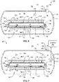
- a tooling assembly 102 for forming a part 190 includes a first tool 120 and a second tool 122.
- the first tool 120 and the second tool 122 are configured to secure a part 190, to be made, between the first tool 120 and the second tool 122.
- the first tool 120 is shaped to define a desired shape of one exterior side of the part 190 and the second tool 122 is shaped to define a desired shape of an opposite side of the part 190.
- the first tool 120 and the second tool 122 are made from a stiff, heat-resistant, and thermally conductive material, such as a metal (e.g., Invar) or composite material.
- the part 190 includes at least two portions that are coupled together to form the part 190. Moreover, the part 190 further includes an interior space 129 that defines an interior surface of the part 190. The interior space 129 is defined between the at least two portions of the part 190.
- the tooling assembly 102 also includes a bladder 126 positioned within the interior space 129 of the part 190 while the part 190 is formed.
- the bladder 126 is shaped to define a desired shape of the interior surface of the part 190. Accordingly, the bladder 126 can have any of various cross-sectional shapes. In the illustrated example, the bladder 126 has a trapezoidal-type cross-sectional shape. However, in other examples, the bladder 126 has another cross-sectional shape, such as square, triangular, circular, ovular, polygonal, and the like.
- the bladder 126 includes an interior 127, which includes a hollow interior channel 128 that extends a length of the bladder 126 or into the page in Figure 1A .
- a wall defining the bladder 126 has a constant thickness, such that the hollow interior channel 128 has a cross-sectional shape corresponding with the cross-sectional shape of the bladder 126.
- the bladder 126 is made of an elastomeric material (e.g. a material exhibiting elastic or rubber-like properties). Accordingly, the bladder 126 is more flexible than the first tool 120 and the second tool 122. The elastic and flexible nature of the bladder 126 allows the bladder 126 to expand when pressurized and contract with the pressure is removed, which helps to cure the part 190. Additionally, the elastic and flexible nature of the bladder 126 enables the bladder 126 to be removed from within the interior space 129 after the part 190 is cured.
- the elastomeric material of the bladder 126 has a hardness of between 50 Shore D and 80 Shore D on the durometer scale.
- the bladder 126 can also be reinforced with fibers, such as fiberglass.
- the part 190 can be any of various parts, for use with any of various stationary or mobile structures, in the illustrated example, the part 190 is a stringer-skin assembly 125 of an aircraft. More specifically, in the illustrated example, the at least two portions of the part 190 include a stringer 130 and a skin 192. The skin 192 forms part of the fuselage of the aircraft. The stringer 130 is coupled to an interior side of the skin 192 and helps strengthen the skin 192. In the illustrated example, the stringer 130 is a hat stringer (e.g., a rounded hat stringer) that includes a hat portion 131 and opposing flange portions 133 extending from the hat portion 131.
- a hat stringer e.g., a rounded hat stringer
- the flange portions 133 are affixed directly to the skin 192 such that the interior space 129 of the part 190 is defined as the hollow space between the hat portion 131 of the stringer 130 and the skin 192.
- the stringer 130 and the skin 192 extend lengthwise into the page with the skin 192 also extending circumferentially about an axis parallel to the longitudinal direction of the stringer 130 and the skin 192.
- the part 190 is made of fiber-reinforced polymeric material in some examples.
- the fibers of the fiber-reinforced polymeric material can be continuous fibers made of carbon.
- the fibers of the fiber-reinforced polymeric material can be made of a material other than carbon, such as glass, and can be continuous or non-continuous.
- the polymeric material of the fiber-reinforced polymeric material is an epoxy or resin, which in some implementations, is a thermoset or thermoplastic polymeric material (e.g., epoxy or resin).
- Each one of the at least two portions of the part 190 e.g., the stringer 130 and the skin 192
- the at least two portions of the part 190 are joined together via a bonding together of the polymeric materials of the two portions.
- the bonding process includes intermixing the polymeric materials of the at least two portions when in a flowable state and then hardening the polymeric materials to complete the bond.
- the polymeric materials are thermoset polymeric materials
- the part 190 can be laid up with the polymeric materials in an uncured state and then heated at or above a cure temperature of the polymeric materials to cure (e.g., harden) together the polymeric materials. Prior to curing the part 190, the polymeric materials are in a pliable, malleable, or deformable state.
- the first tool 120 is a mandrel or inside mold line tool and the second tool 122 is a caul sheet.
- the mandrel can be a one-piece or seamless mandrel (e.g., seamless at the stringer 130) as shown in Figure 1A (e.g., having a one-piece construction) or a multi-part mandrel with a seam 121 (e.g., having a multi-part construction), between two adjoined portions 120A-120B of the mandrel, at the stringer 130 as shown in Figure 1B .
- the bladder 126 is located at the seam 121 between the two adjoined portions 120A-120B of the mandrel.
- the bladder 126 extends widthwise from one portion 120A of the mandrel, across the seam 121 between the adjoined portions 120A-120B, to the other portion 120B of the mandrel. Put another way, the bladder 126 is interposed between the seam 121 and the second tool 122.
- a caul sheet is relatively thin compared to the mandrel.
- heat is transferred to the part 190 through the first tool 120, the second tool 122, and the bladder 126. Because the caul sheet is thin, heat transfer through the second tool 122 may be efficient enough to heat a portion of the part 190 relatively quickly. However, because the mandrel is thicker than the caul sheet, heat transfer through the first tool 120 may be less efficient, thus slowing the heating of other portions of the part 190 and thus slowing the cure process of the part 190 or creating lagging temperature gradients in the part 190. Alternatively, the part 190 may have a variable thickness that tends to slow the cure process in such thicker portions of the part 190.
- the mandrel can include heat transfer restrictions in some examples that further slow the transfer of heat through the first tool 120 to the part 190.
- the first tool 120 is a mandrel with a localized thickness increase, such as due to the added robustness of the mandrel at the seam of two adjoining parts of the mandrel.
- the first tool 120 of Figure 1B has a thickness t2 proximate the stringer 130 that is greater than a thickness t1 of the first tool 120 of Figure 1A at a location proximate the stringer 130.
- the thickness t2 being greater than the thickness t1 , increases the thermal mass of the first tool 120 of Figure 1B proximate the stringer 130 compared to the first tool 120 of Figure 1A .
- the increased thermal mass requires more time to reach curing temperatures compared to surrounding portions of the first tool 120. Accordingly, the increased thermal mass of the first tool 120 of Figure 1B has a tendency to cause lagging temperature gradients in the part 190, which may result in increased cure cycle times.
- the bladder 126 is part of bladder assembly 124, and the bladder assembly 124 enables the flow of heated fluid through the bladder 126, which helps to reduce lagging temperature gradients in the part 190.
- the system 100 includes an autoclave 110 having an autoclave vessel 112. Accordingly, the system 100 is considered an autoclave system.
- the autoclave vessel 112 defines an interior cavity 150, which is configured to contain the tooling assembly 102 and the part 190 being cured.
- the interior cavity 150 also contains a fluid 152, which can be a gas.
- the fluid 152 is an inert gas. More specifically, according to one example, the fluid 152 is a nitrogen gas. The inert nature of the fluid 152 helps prevent unintended reactions, such as combustion events, within the autoclave vessel 112.
- the fluid 152 is a gas other than an inert gas, such as air, which in some situations would help to retain heat in the autoclave vessel 112.
- the fluid 152 is initially supplied to the autoclave vessel 112 from a fluid source (not shown) and can be replenished while the part 190 is cured.
- the autoclave vessel 112 is hermetically sealable such that the fluid 152 in the interior cavity 150 can be pressurized relative to an exterior 186 of the autoclave vessel 112 outside the interior cavity 150.
- the autoclave 110 additionally includes a heater that is operable to heat the fluid 152 contained within the autoclave vessel 112 to temperature at least at a cure temperature of the polymeric materials of the part 190 being formed. More specifically, the fluid 152 within the autoclave vessel 112 is heated by at least one heater to an operational temperature conducive to curing the part 190. The operational temperature of the fluid 152 is dependent on the curing temperature of the part 190.
- the operational temperature of the fluid 152 in the autoclave vessel 112 is at least 350 degrees Fahrenheit, in certain implementations, and at least 400 degrees Fahrenheit, in some implementations. In yet other implementations, the operational temperature of the fluid 152 in the autoclave vessel 112 is as low as 180 degrees and as high as at least 600 degrees Fahrenheit.
- the fluid 152 can be circulated through the interior cavity 150 and around the tooling assembly 102 and the part 190 by a circulator (not shown). Circulation of the fluid 152 around the tooling assembly 102 and the part 190 helps to accelerate the transfer of heat from the fluid 152 to the tooling assembly 102 via convection by improving the efficiency of the heat transfer process.
- the fluid 152 within the autoclave vessel 112 is pressurized to an operational pressure P1 above atmospheric pressure P3.
- the fluid 152 is pressurized to an operation pressure P1 of at least 90 pounds-per-square-inch (psi). Pressurizing the fluid 152 within the autoclave vessel 112 promotes the transfer of heat to the part 190 and improves the rate at which the part 190 cures. Additionally, pressurizing the fluid 152 in the autoclave vessel 112 helps to compress the part 190, which promotes a reduction in the voids or air pockets within the laminated features of the part 190.
- Pressurization of the fluid 152 can be provided by a pressurized fluid source that introduces pressurized gas into the autoclave vessel 112 prior to curing the part 190.
- additional pressure is applied to the part 190 during the curing process by isolating the part 190, relative to the interior cavity 150 of the autoclave vessel 112, within a hermetically sealed container and pulling pressure from the hermetically sealed container to create vacuum conditions within the hermetically sealed container.
- the autoclave 110 facilitates curing of the uncured polymer of the fiber-reinforced polymer material of the part 190 by heating the uncured polymer up to at least the curing temperature of the polymer.
- heating the uncured polymer in this manner results in the hardening of the polymer by cross-linking polymer chains of the polymer. Once hardened via the curing process, the chemical transformation of the polymer is irreversible.
- the uncured polymer is uniformly heated to ensure the chemical composition and strength of the cured fiber-reinforced polymer material is consistent throughout the part 190.
- the system 100 further includes a bladder assembly 124, which, when used in conjunction with the autoclave 110, helps facilitate faster and uniform heating of the uncured fiber-reinforced polymer material of the part 190 by utilizing the bladder 126 to distribute heat to the part 190.
- the bladder assembly 124 includes the bladder 126.
- the fluid 152 within the interior cavity 150 of the autoclave vessel 112 is circulated through the interior 127 of the bladder 126, which helps to distribute heat to less accessible surfaces, such as internal surfaces, of the part 190, which may not be heated as quickly as more accessible surfaces, such as external surfaces.
- the bladder assembly 124 is configured to help flow heated and pressurized fluid through the bladder 126 and thus to the internal surfaces of the part 190 to promote faster and more uniform heating of the part 190.
- the bladder assembly 124 further includes an intake port 134, an exhaust port 138, and a pressure control device 146.
- the intake port 134 is fluidically coupled with the interior 127 of the bladder 126.
- the exhaust port 138 is fluidically coupled with the interior 127 of the bladder 126.
- the intake port 134 and the exhaust port 138 include a fluid conduit open to the interior 127 of the bladder 126.
- the intake port 134 and the exhaust port 138 are open to the interior 127 of the bladder 126 by passing through a wall of the bladder 126.
- the bladder assembly 124 is positioned at least partially in the interior cavity 150 of the autoclave vessel 112 when curing of the part 190 is performed. In some examples, a substantial portion or an entirety of the bladder assembly 124 is positioned in the interior cavity 150 of the autoclave vessel 112. In one example, an entirety of the bladder assembly 124, with the exception of all or a portion of the pressure control device 146, is positioned within the interior cavity 150.
- the intake port 134 is open to and thus fluidically coupled with the interior cavity 150 of the autoclave vessel 112. Accordingly, the fluid 152 in the interior cavity 150 is free or allowed to enter the interior 127 of the bladder 126 through the intake port 134. Moreover, the fluid 152, when in the interior 127 of the bladder 126, is free or allowed to exit the interior 127 of the bladder 126 through the exhaust port 138.
- the pressure control device 146 is fluidically coupled with the exhaust port 138. Moreover, the pressure control device 146 is configured to control or limit a pressure drop across the interior 127 of the bladder 126. The pressure drop induces a portion of the fluid 152 in the interior cavity 150 to flow, as indicated by arrows 154, into the interior 127 of the bladder 126 through the intake port 134, flow through the interior 127 of the bladder 126, and flow out of the interior 127 of the bladder 126. Accordingly, the pressure control device 146 can be considered and defined as a flow control device that is configured to control or regulate the flow of the fluid 152 through the interior 127 of the bladder 126 and from the interior 127 to the exterior 186.
- the bladder 126 includes a first end portion 140 and a second end portion 142.
- the first end portion 140 and the second end portion 142 define opposite ends of the interior 127, including the hollow interior channel 128, of the bladder 126.
- the bladder 126, including the hollow interior channel 128, extends lengthwise from the first end portion 140 to the second end portion 142.
- the intake port 134 passes through a wall of the bladder 126 at the first end portion 140. Accordingly, the bladder 126 includes an intake opening or aperture at the first end portion 140 that at least partially defines the intake port 134.
- the bladder assembly 124 further includes an intake plug 132.
- the intake plug 132 is fixed to the first end portion 140 of the bladder 126.
- the intake plug 132 includes an intake conduit, fluidically open to the interior cavity 150 of the autoclave vessel 112 and to the intake opening in the wall of the bladder 126 that at least partially defines the intake port 134.
- the intake port 134 passes through and is defined by the intake opening in the wall of the bladder 126 and the intake conduit formed in the intake plug 132.
- the intake plug 132 includes one or more fittings configured to fixedly attach to the first end portion 140 of the bladder 126.
- the intake plug 132 has a one-piece monolithic and seamless construction in some examples and a multi-piece construction in other examples. Moreover, the intake plug 132 can be permanently fixedly attached to the bladder 126 or be configured to selectively releasably attach to the bladder 126.
- the bladder assembly 124 also includes an exhaust plug 136 that is fixed to the second end portion 142 of the bladder 126.
- the exhaust port 138 passes through a wall of the bladder 126 at the second end portion 142.
- the bladder 126 includes an exhaust opening or aperture at the second end portion 142 that at least partially defines the exhaust port 138.
- the exhaust plug 136 includes an exhaust conduit, fluidically open to the exhaust opening in the wall of the bladder 126, that at least partially defines the exhaust port 138, and to the pressure control device 146.
- the exhaust conduit in the exhaust plug 136 is not open to the interior cavity 150 of the autoclave vessel 112, but instead opens to the pressure control device 146.
- the exhaust port 138 passes through and is defined by the exhaust opening in the wall of the bladder 126 and the exhaust conduit formed in the exhaust plug 136.
- the exhaust plug 136 includes one or more fittings configured to fixedly attach to the second end portion 142 of the bladder 126.
- the exhaust plug 136 has a one-piece monolithic and seamless construction in some examples and a multi-piece construction in other examples.
- the exhaust plug 136 can be permanently fixedly attached to the bladder 126 or be configured to selectively releasably attach to the bladder 126.
- the bladder assembly 124 includes an exhaust tube 144 that fluidically couples the exhaust port 138 to the pressure control device 146.
- the pressure control device 146 is fluidically open, whether directly or indirectly, to an exterior 186 outside the interior cavity 150 of the autoclave vessel 112. Accordingly, the fluid 152 exiting the interior 127 of the bladder 126 through the exhaust port 138 is expelled into the exterior 186 (e.g., atmosphere), as indicated by a directional arrow 154, via the exhaust tube 144 and the pressure control device 146 .
- the pressure control device 146 is located within the interior cavity 150 of the autoclave vessel 112 and is open to the exterior 186 via an extension tube (not shown) coupled to the wall of the autoclave vessel 112. According to other examples, as shown, the pressure control device 146 is coupled to the wall of the autoclave vessel 112. In yet alternative examples, the pressure control device 146 is located in the exterior 186 outside the interior cavity 150 and the exhaust tube 144 passes through the wall of the autoclave vessel 112.
- the pressure control device 146 being open to the exterior 186 at the atmospheric pressure P3 and in fluidic communication with the fluid 152 at the operational pressure PI, via the bladder 126, is configured to control the flow of fluid 152 from the interior cavity 150 and the bladder 126 in a manner that results in a drop of the pressure P2 of the fluid 152 in the bladder 126 to below the operation pressure P1 and above the atmospheric pressure P3.
- the drop in pressure from P1 to P2 and from P2 to P3 facilitates the flow of the fluid 152 through the interior 127 of the bladder 126.
- the pressure control device 146 limits the pressure drop from P1 to P2 (i.e., the pressure drop across the interior 127 of the bladder 126) to greater than zero, but less than or equal to a pressure-drop percentage threshold.
- the pressure-drop percentage threshold is 5%. According to other examples, the pressure-drop percentage threshold is between 2% and 4%.
- the pressure control device 146 is a passive device configured to passively control the pressure drop across the interior 127 of the bladder 126.
- the pressure control device 146 can be a passive pressure control device 147, such as a passive flow control valve or orifice.
- the passive flow control valve enables a constant flow rate through the valve independently of pressure changes at the inlet of the valve.
- the orifice which can be a fixed-diameter orifice, provides a constant pressure drop across the orifice.
- the passive pressure control device 147 can be designed to provide a fixed pressure drop across the interior 127 of the bladder 126.
- the pressure control device 146 is an active device configured to actively control the pressure drop across the interior 127 of the bladder 126.
- the pressure control device 146 can be an active pressure control device 149, such as a controllable or adjustable valve or orifice.
- the active pressure control device 149 enables a variable or adjustable flow rate through the device in response to pressure changes at the inlet of the device. Accordingly, the active pressure control device 149 can be controlled to provide a changing pressure drop or a fixed pressure drop across the interior 127 of the bladder 126.
- the bladder assembly 124 additionally includes a pressure sensor 174 that is fluidically coupled with the exhaust port 138 between the exhaust port 138 and the pressure control device 146.
- the pressure sensor 174 is configured to sense or detect the pressure P2 of the fluid 152 exiting the exhaust port 138 before the fluid 152 passes through the pressure control device 146.
- active control of the pressure drop using the active pressure control device 149 can be dependent on (e.g., actuatable in response to) feedback from the pressure sensor 174.
- the system 100 further includes a controller 160 in certain examples.
- the controller 160 is operably coupled with the pressure sensor 174 and the active pressure control device 149.
- the controller 160 is configured to receive feedback from the pressure sensor 174, such as in the form of electronic signals (e.g., pressure readings) indicative of the pressure P2 of the fluid 152 sensed by the pressure sensor 174, and command or control actuation of the active pressure control device 149 to adjust the flow rate through the device in response to the feedback from the pressure sensor 174. More specifically, in some implementations, the controller 160 compares the pressure readings from the pressure sensor 174 to a predetermined pressure-drop range and controls the active pressure control device 149 to achieve a pressure drop from the pressure P1 to the pressure P2 that falls within the predetermined pressure-drop range.
- the comparison performed by the controller 160 includes receiving data regarding the operational pressure P1 within the interior cavity 150 of the autoclave vessel 112 and determining a difference between the operational pressure P1 and the pressure P2 (as sensed by the pressure sensor 174), which is equal to the actual pressure drop across the interior 127 of the bladder 126.
- the data regarding the operational pressure P1 can be obtained from a pressure sensor in pressure sensing communication with the interior cavity 150.
- the controller 160 commands the active pressure control device 149 to make flow throughput adjustments to ensure the difference between the operational pressure P1 and the pressure P2 stays within the predetermined pressure-drop range.
- the controller 160 further utilizes the atmospheric pressure P3 to determine the degree of throughput adjustments necessary to achieve a desired pressure drop across the interior 127 of the bladder 126.
- the fluid 152 flows through the hollow interior channel 128 of the interior 127 of the bladder 126 from the first end portion 140 to the second end portion 142.
- the bladder assembly 124 includes both the intake plug 132 at the first end portion 140 and an exhaust plug 136 at the second end portion 142.
- the bladder assembly 124 does not include the exhaust plug 136 and the fluid 152 flows through the interior 127 of the bladder 126 in a first direction from the first end portion 140 to the second end portion 142 and is then redirected to flow in a second direction, opposite the first direction, from the second end portion 142 to the first end portion 140.
- the exhaust port 138 passes through an exhaust conduit formed in the intake plug 132.
- the intake plug 132 includes both an intake conduit, which forms a portion of the intake port 134, and a fluidically separate exhaust conduit, which forms a portion of the exhaust port 138.
- the second end portion 142 of the bladder 126 is closed.
- the bladder assembly 124 of Figures 4, 5 , 9 , and 10 having one plug (i.e., the intake plug 132) simplifies the construction of the bladder assembly 124. Moreover, because securing fittings or connections, such as the intake plug 132, to the bladder 126 can be difficult in certain situations, reducing the number of fittings in the bladder assembly 124 can be advantageous. Additionally, a bladder assembly 124 with only one plug on one end portion of the bladder 126 makes removal of the bladder 126 from the part 190 following curing easier than a bladder assembly 124 with two plugs on corresponding opposite end portions of the bladder 126.
- the bladder assembly 124 further includes a tube 180 that facilitates the dual directionality of the flow of the fluid 152.
- the tube 180 is hollow and passes through the hollow interior channel 128 from the first end portion 140 of the bladder 126 toward the second end portion 142 of the bladder 126.
- the tube 180 is fluidically coupled with the intake port 134 at the first end portion 140 of the bladder 126. Additionally, the tube 180 terminates before a closed end of the second end portion 142 of the bladder 126. Therefore, the tube 180 is open to the hollow interior channel 128 proximate the second end portion 142 of the bladder 126.
- the tube 180 has a cross-sectional area smaller than the cross-sectional area of the hollow interior channel 128.
- the tube 180 passes through a central portion of (e.g., is concentric with) the hollow interior channel 128. Accordingly, in these examples, the hollow interior channel 128 circumscribes (e.g., circumferentially surrounds) the tube 180.
- the pressure drop across the interior 127 of the bladder 126 between the intake port 134 and the exhaust port 138 induces flow of the fluid 152 from the interior cavity 150 of the autoclave vessel 112 into the intake port 134.
- the fluid 152 flows through the tube 180 away from the first end portion 140 of the bladder 126 toward the second end portion 142 of the bladder 126.
- the fluid 152 then exits the tube 180 into the hollow interior channel 128 proximate the second end portion 142 and, due to the closed end of the bladder 126 at the second end portion 142, reverses direction back toward the first end portion 140 through the hollow interior channel 128 on the outside of the tube 180.
- the fluid 152 When back at the first end portion 140, the fluid 152 exits the hollow interior channel 128 through the exhaust port 138 and ultimately exits the autoclave vessel 112. As the fluid 152 flows from the second end portion 142 toward the first end portion 140, heat from the fluid 152 is transferred to the bladder 126, which is subsequently transferred to the part 190 for curing the part 190.
- the control of the pressure drop across the interior 127 of the bladder 126 and the flow of the fluid 152 through the interior 127 of the bladder 126 can be performed passively, as shown in Figure 4 , or actively, as shown in Figure 5 . As shown, the features for passively and actively controlling the pressure drop and flow of the fluid 152 can be similar to or the same as those shown in and described in associated with Figures 2 and 3 , respectively.
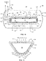
- the bladder 126 includes one or more interior walls that divides the hollow interior channel 128 into multiple separate sub-channels.
- the bladder 126 of Figures 13A and 13B includes an interior wall 193 that divides the hollow interior channel 128 into an outflow sub-channel 194 and an inflow sub-channel 196.
- the outflow sub-channel 194 is fluidically coupled with the intake port 134 and the inflow sub-channel 196 is fluidically coupled with the exhaust port 138.
- the fluid 152 flows away from the intake port 134, into the page in Figures 13A and 13B (as indicated by an 'X'), and the fluid 152 flows back, in an opposite direction, toward the exhaust port 138, out of the page in Figures 13A and 13B (as indicated by an dot).
- the interior wall 193 terminates before a closed end of the bladder 126 and the closed end of the bladder 126 redirects the flow of the fluid 152 from the outflow sub-channel 194 to the inflow sub-channel 196.
- the interior wall 193 is a vertical interior wall and the outflow sub-channel 194 and the inflow sub-channel 196 are on opposite sides of the bladder 126.
- the interior wall 193 is a horizontal interior wall and the outflow sub-channel 194 and the inflow sub-channel 196 are on bottom and top portions of the bladder 126, respectively.
- the outflow sub-channel 194 and the inflow sub-channel 196 are on bottom and top portions of the bladder 126, respectively.
- multiple interior walls can be employed to create more than two sub-channels.
- the bladder 126 includes multiple layers that form the wall of the bladder 126.
- the bladder 126 includes an outer layer 170 and an inner layer 172.
- the outer layer 170 defines an exterior surface of the bladder 126 and the inner layer 172 defines an interior surface of the bladder 126.
- the inner layer 172 defines the hollow interior channel 128 of the interior 127 of the bladder 126.
- the outer layer 170 and the inner layer 172 are made from the same material in certain examples. Alternatively, in other examples, the outer layer 170 and the inner layer 172 are made from different materials.
- the outer layer 170 and the inner layer 172 are separately formed and coupled together (e.g., bonded, adhered, fastened, etc.) to form the bladder 126.
- the bladder 126 can include more than two layers in some examples.
- the bladder 126 of Figures 6-8 includes at least one fluid flow conduit 176 interposed between the outer layer 170 and the inner layer 172.
- the fluid flow conduit 176 may be defined between a groove formed in the outer layer 170 and the opposing surface of the inner layer 172 (as shown), a groove formed in the inner layer 172 and the opposing surface of the outer layer 170, or grooves formed in both the inner layer 172 and the outer layer 170. Additionally, the fluid flow conduit 176 can be located at any of various locations within the bladder 126, such as a bottom portion 182 of the bladder 126 (as shown), a top portion 184 of the bladder 126, or one of two side portions of the bladder 126.
- the fluid flow conduit 176 is located at a location of the bladder 126 corresponding with locations on the part 190 that can benefit from the additional heat flowing through the bladder 126.
- the fluid flow conduit 176 forms part of the interior 127 of the bladder 126.
- the interior 127 of the bladder 126 can include the hollow interior channel 128 and a separate one or more fluid flow conduits 176.
- the fluid flow conduit 176 extends from the first end portion 140 of the bladder 126 to the second end portion 142 of the bladder 126.
- the fluid flow conduit 176 is fluidically coupled with the intake port 134, which is partially formed through the intake plug 132 fixed to the first end portion 140, and at the second end portion 142, the fluid flow conduit 176 is fluidically coupled with the exhaust port 138, which is partially formed through the exhaust plug 136 fixed to the second end portion 142.
- At least one of the intake plug 132 or the exhaust plug 136 includes a vent 198 that passes through the corresponding one or both of the intake plug 132 and the exhaust plug 136 and passes through the wall of the bladder 126.
- the vent 198 enables the hollow interior channel 128 to be pressurized to the operational pressure P1 of the fluid 152 in the interior cavity 150.
- the pressure drop across the interior 127 of the bladder 126 between the intake port 134 and the exhaust port 138 induces flow of the fluid 152 from the interior cavity 150 of the autoclave vessel 112 into the intake port 134.
- the fluid 152 flows through the fluid flow conduit 176 away from the first end portion 140 of the bladder 126 toward the second end portion 142 of the bladder 126.
- the fluid 152 then exits the fluid flow conduit 176 into the exhaust port 138 and ultimately exits the autoclave vessel 112.
- heat from the fluid 152 is transferred to the bladder 126, which is subsequently transferred to the part 190 for curing the part 190.
- the control of the pressure drop across the interior 127 of the bladder 126 (which in this example is a pressure drop across the fluid flow conduit 176), and the flow of the fluid 152 through the interior 127 of the bladder 126 can be performed passively, as shown in Figure 6 , or actively, as shown in Figure 7 .
- the features for passively and actively controlling the pressure drop and flow of the fluid 152 can be similar to or the same as those shown in and described in associated with Figures 2 and 3 , respectively.
- the fluid flow conduit 176 can be larger than as shown.
- the bladder 126 includes a plurality of fluid flow conduits 176 between the outer layer 170 and the inner layer 172 and fluidically coupled with the intake port 134 and the exhaust port 138.
- the fluid flow conduits 176 are shown to be concentrated on the bottom portion 182 of the bladder 126, in other examples, the fluid flow conduits 176 can be concentrated on additional or alternative portions of the bladder 126 (e.g., to transfer heat to targeted portions of the part 190) or the fluid flow conduits 176 can be evenly distributed around the bladder 126 (e.g., to promote an even distribution of heat to the part 190).
- the bladder 126 of Figures 9-11 includes at least one fluid flow conduit 176 interposed between the outer layer 170 and the inner layer 172.
- the fluid flow conduit 176 of Figures 9-11 is not fluidically coupled with an exhaust port 138 in an exhaust plug 136, but rather is fluidically coupled with a second fluid flow conduit 178 that is fluidically coupled with an exhaust port 138 in the intake plug 132.
- the fluid flow conduit 176 is considered an inflow conduit and the second fluid flow conduit 178 is considered an outflow conduit.
- the fluid flow conduit 176 and the second fluid flow conduit 178 together form a continuous fluid flow conduit that extends from the first end portion 140 of the bladder 126 to the second end portion 142 of the bladder 126, wraps around the closed end of the bladder 126 at the second end portion 142, and extends from the second end portion 142 back to the first end portion 140.
- the fluid flow conduit 176 and the second fluid flow conduit 178 can be located at any of various opposing locations within the bladder 126.
- the fluid flow conduit 176 extends along a first side of the bladder 126
- the second fluid flow conduit 178 extends along a second side 184 of the bladder 126.
- the first side of the bladder is the bottom portion 182 and the second side of the bladder is top portion 184.
- the fluid flow conduit 176 can be located in the bottom portion 182 of the bladder 126 and the second fluid flow conduit 178 can be located in the top portion 184 of the bladder 126 (as shown).
- these locations can be reversed or the locations can be different, such as opposing side portions.
- the fluid flow conduit 176 and the second fluid flow conduit 178 are located at locations of the bladder 126 corresponding with locations on the part 190 that can benefit from the additional heat flowing through the bladder 126.
- the fluid flow conduit 176 and the second fluid flow conduit 178 form part of the interior 127 of the bladder 126.
- the interior 127 of the bladder 126 can include the hollow interior channel 128 and a separate one or more fluid flow conduits 176 and second fluid flow conduits 178.
- the pressure drop across the interior 127 of the bladder 126 between the intake port 134 and the exhaust port 138 induces flow of the fluid 152 from the interior cavity 150 of the autoclave vessel 112 into the intake port 134.
- the fluid 152 flows through the fluid flow conduit 176 away from the first end portion 140 of the bladder 126 toward the second end portion 142 of the bladder 126.
- the fluid 152 then changes direction and enters the second fluid flow conduit 178.
- the fluid 152 flows along the second fluid flow conduit 178 away from the second end portion 142 of the bladder 126 toward the first end portion 140. From the second end portion 142, the fluid 152 flows into the exhaust port 138 and then ultimately exits the autoclave vessel 112.
- the fluid flow conduit 176 and the second fluid flow conduit 178 can be larger than as shown.
- the bladder 126 includes a plurality of fluid flow conduits 176, spaced apart from each other, and second fluid flow conduits 178, spaced apart from each other, between the outer layer 170 and the inner layer 172 and fluidically coupled with the intake port 134 and the exhaust port 138.
- the fluid flow conduits 176 and the second fluid flow conduits 178 are shown to be concentrated on the bottom portion 182 and the top portion 184 of the bladder 126, respectively, in other examples, the fluid flow conduits 176 and the second fluid flow conduits 178 can be concentrated on additional or alternative portions of the bladder 126 (e.g., to transfer heat to targeted portions of the part 190) or the fluid flow conduits 176 and the second fluid flow conduits 178 can be evenly distributed around the bladder 126 (e.g., to promote an even distribution of heat to the part 190).
- the method 200 includes (block 202) positioning the bladder 126 within the interior space 129 of the part 190 and (block 204) positioning the part 190 and the bladder 126 within the interior cavity 150 of the autoclave vessel 112.
- the method 200 also includes (block 206), while in the interior cavity 150 of the autoclave vessel 112, shaping the interior space 129 of the part 190 with the bladder 126.
- the method further includes (block 208), while shaping the interior space 129 of the part 190 with the bladder 126, creating a pressure drop across the interior 127 of the bladder 126, with the pressure control device 146 fluidically coupled with the interior 127 of the bladder 126 and the exterior 186 outside the autoclave vessel 112, to induce flow of the fluid 152, contained within the autoclave vessel 112, through the interior 127 of the bladder 126 and from the interior 127 of the bladder 126 to the exterior 186 outside the autoclave vessel 112.
- the fluid 152 flows into the interior 127 of the bladder 126 from the first end portion 140 of the bladder 126 and flows out of the interior 127 of the bladder 126 to the exterior 186 outside the autoclave vessel 112 from the second end portion 142 of the bladder 126.
- the fluid 152 flows into the interior 127 of the bladder 126 from the first end portion 140 of the bladder 126 and flows out of the interior 127 of the bladder 126 to the exterior 186 outside the autoclave vessel 112 from the first end portion 140 of the bladder 126.
- the fluid 152 can flow through the interior 127 of the bladder 126 in a first direction from the first end portion 140 of the bladder 126 to the second end portion 142 of the bladder 126 and in a second direction, opposite the first direction, from the second end portion 142 of the bladder 126 to the first end portion 140 of the bladder 126.
- the fluid 152 flows through the interior 127 of the bladder 126 between an inner layer 172 of the bladder 126 and an outer layer of the bladder 170.
- the method 200 further includes comparing the first pressure P1 of the fluid 152 within the autoclave vessel 112 to the second pressure P2 of the fluid 152 within the interior 127 of the bladder 126 to provide a comparison between the first pressure P1 and the second pressure P2.
- the method 200 can also include controlling actuation of the pressure control device 146, to control the pressure drop across the interior 127 of the bladder 126, in response to the comparison between the first pressure P1 and the second pressure P2.
- the method 200 can involve using the disclosed bladder assembly 124 to create the pressure drop across the interior 127 of the bladder 126 to induce flow of the fluid 152, contained within the autoclave vessel 112, through the interior 127 of the bladder 126 and from the interior 127 of the bladder 126 to the exterior 186 outside the autoclave vessel 112.
- the method 200 can involve using the bladder assembly 124 illustrated in any of Figures 2, 3 , 4, 5 , 6, 7 , 9 , or 10 to create the pressure drop to induce the flow of fluid 152.
- the bladder 126 of method 200 can be the bladder 126 illustrated in any of Figures 1A-11 , 13A, and 13B .
- instances in this specification where one element is "coupled" to another element can include direct and indirect coupling.
- Direct coupling can be defined as one element coupled to and in some contact with another element.
- Indirect coupling can be defined as coupling between two elements not in direct contact with each other, but having one or more additional elements between the coupled elements.
- securing one element to another element can include direct securing and indirect securing.
- adjacent does not necessarily denote contact. For example, one element can be adjacent another element without being in contact with that element.
- the phrase "at least one of', when used with a list of items, means different combinations of one or more of the listed items may be used and only one of the items in the list may be needed.
- the item may be a particular object, thing, or category.
- "at least one of' means any combination of items or number of items may be used from the list, but not all of the items in the list may be required.
- "at least one of item A, item B, and item C" may mean item A; item A and item B; item B; item A, item B, and item C; or item B and item C.
- "at least one of item A, item B, and item C” may mean, for example, without limitation, two of item A, one of item B, and ten of item C; four of item B and seven of item C; or some other suitable combination.
- first, second, etc. are used herein merely as labels, and are not intended to impose ordinal, positional, or hierarchical requirements on the items to which these terms refer. Moreover, reference to, e.g., a “second” item does not require or preclude the existence of, e.g., a "first” or lower-numbered item, and/or, e.g., a "third" or higher-numbered item.
- a system, apparatus, structure, article, element, component, or hardware “configured to” perform a specified function is indeed capable of performing the specified function without any alteration, rather than merely having potential to perform the specified function after further modification.
- the system, apparatus, structure, article, element, component, or hardware “configured to” perform a specified function is specifically selected, created, implemented, utilized, programmed, and/or designed for the purpose of performing the specified function.
- "configured to” denotes existing characteristics of a system, apparatus, structure, article, element, component, or hardware which enable the system, apparatus, structure, article, element, component, or hardware to perform the specified function without further modification.
- a system, apparatus, structure, article, element, component, or hardware described as being “configured to” perform a particular function may additionally or alternatively be described as being “adapted to” and/or as being “operative to” perform that function.
- the schematic flow chart diagrams included herein are generally set forth as logical flow chart diagrams. As such, the depicted order and labeled steps are indicative of one example of the presented method. Other steps and methods may be conceived that are equivalent in function, logic, or effect to one or more steps, or portions thereof, of the illustrated method. Additionally, the format and symbols employed are provided to explain the logical steps of the method and are understood not to limit the scope of the method. Although various arrow types and line types may be employed in the flow chart diagrams, they are understood not to limit the scope of the corresponding method. Indeed, some arrows or other connectors may be used to indicate only the logical flow of the method. For instance, an arrow may indicate a waiting or monitoring period of unspecified duration between enumerated steps of the depicted method. Additionally, the order in which a particular method occurs may or may not strictly adhere to the order of the corresponding steps shown.
Landscapes
- Engineering & Computer Science (AREA)
- Mechanical Engineering (AREA)
- Chemical & Material Sciences (AREA)
- Composite Materials (AREA)
- Structural Engineering (AREA)
- Civil Engineering (AREA)
- Architecture (AREA)
- Physics & Mathematics (AREA)
- Health & Medical Sciences (AREA)
- Oral & Maxillofacial Surgery (AREA)
- Thermal Sciences (AREA)
- Casting Or Compression Moulding Of Plastics Or The Like (AREA)
- Moulding By Coating Moulds (AREA)
Applications Claiming Priority (1)
| Application Number | Priority Date | Filing Date | Title |
|---|---|---|---|
| US202163133667P | 2021-01-04 | 2021-01-04 |
Publications (1)
| Publication Number | Publication Date |
|---|---|
| EP4029678A1 true EP4029678A1 (de) | 2022-07-20 |
Family
ID=79021695
Family Applications (1)
| Application Number | Title | Priority Date | Filing Date |
|---|---|---|---|
| EP21217350.4A Pending EP4029678A1 (de) | 2021-01-04 | 2021-12-23 | Autoklavsystem, blasenanordnung und zugehöriges verfahren zur herstellung eines teils |
Country Status (3)
| Country | Link |
|---|---|
| US (1) | US20220212425A1 (de) |
| EP (1) | EP4029678A1 (de) |
| CN (1) | CN114714643A (de) |
Citations (3)
| Publication number | Priority date | Publication date | Assignee | Title |
|---|---|---|---|---|
| DE3226220A1 (de) * | 1982-07-14 | 1984-01-26 | Julius Cronenberg Ohg, 5760 Arnsberg | Form und verfahren zur herstellung konischer maste aus glasfaserverstaerktem kunststoff |
| EP2497623A1 (de) * | 2009-11-06 | 2012-09-12 | Kawasaki Jukogyo Kabushiki Kaisha | Vorrichtung zur herstellung einer verbundmaterialstruktur |
| US20120312848A1 (en) * | 2011-05-20 | 2012-12-13 | Jac Products, Inc. | Advanced Composite Vehicle Article Carrier Component And Method Of Making Same |
Family Cites Families (6)
| Publication number | Priority date | Publication date | Assignee | Title |
|---|---|---|---|---|
| IT1223923B (it) * | 1988-11-22 | 1990-09-29 | Ferrari Engineering Spa | Procedimento per la costruzione di elementi monolitici cavi in materiale composito in particolare in fibra di carbonio |
| US5266249A (en) * | 1992-01-02 | 1993-11-30 | Fusion Composites, Inc. | Method of forming a fiber reinforced plastic structure |
| US20090243160A1 (en) * | 2006-02-13 | 2009-10-01 | Douglas Chiang | Bicycle Cranks Composed of Composite Material and Metal Parts and Method for Making the Same |
| US9375865B2 (en) * | 2011-12-27 | 2016-06-28 | Spirit Aerosystems, Inc. | Autoclave health monitoring and control system |
| US10507601B2 (en) * | 2016-05-17 | 2019-12-17 | Rubbercraft Corporation Of California, Ltd. | Tri-layer bladder and related systems and methods for fabricating composite structures |
| US10710319B2 (en) * | 2017-08-02 | 2020-07-14 | The Boeing Company | Controlling application of forces to different portions of object surface using bladder |
-
2021
- 2021-12-20 US US17/556,688 patent/US20220212425A1/en active Pending
- 2021-12-23 EP EP21217350.4A patent/EP4029678A1/de active Pending
-
2022
- 2022-01-04 CN CN202210003142.8A patent/CN114714643A/zh active Pending
Patent Citations (3)
| Publication number | Priority date | Publication date | Assignee | Title |
|---|---|---|---|---|
| DE3226220A1 (de) * | 1982-07-14 | 1984-01-26 | Julius Cronenberg Ohg, 5760 Arnsberg | Form und verfahren zur herstellung konischer maste aus glasfaserverstaerktem kunststoff |
| EP2497623A1 (de) * | 2009-11-06 | 2012-09-12 | Kawasaki Jukogyo Kabushiki Kaisha | Vorrichtung zur herstellung einer verbundmaterialstruktur |
| US20120312848A1 (en) * | 2011-05-20 | 2012-12-13 | Jac Products, Inc. | Advanced Composite Vehicle Article Carrier Component And Method Of Making Same |
Also Published As
| Publication number | Publication date |
|---|---|
| CN114714643A (zh) | 2022-07-08 |
| US20220212425A1 (en) | 2022-07-07 |
Similar Documents
| Publication | Publication Date | Title |
|---|---|---|
| US8906489B2 (en) | Method for producing a fibre composite component for aviation and spaceflight | |
| US7530530B2 (en) | Assembly for securing a stringer to a substrate | |
| US8057721B2 (en) | Resin infusion mold tool system and vacuum assisted resin transfer molding with subsequent pressure bleed | |
| US8372327B2 (en) | Method for resin transfer molding composite parts | |
| EP2190650B1 (de) | Herstellungsverfahren einer hohlen verbundstruktur | |
| US8337740B2 (en) | Reinforced internal composite structures | |
| US9126376B2 (en) | Method and a device for the manufacture of a fibre-reinforced thermoplastic composite module | |
| EP3088152B1 (de) | Verfahren zur herstellung von verbundteilen und form | |
| CN106851861B (zh) | 实现优化的固化结构的高级多栅热源及其制造方法 | |
| KR20080066941A (ko) | 벌크 수지 주입 시스템 장치 및 방법 | |
| JP2009542493A (ja) | 航空機または宇宙船に用いられる複合繊維部品を製造する方法及び成形コア材並びにこれらより得られる複合繊維部品 | |
| WO2008089334A2 (en) | Method and apparatus for molding composite articles | |
| CN111231367A (zh) | 一种曲面复合材料制件的成型方法 | |
| US10807280B2 (en) | Method of extracting a tooling mandrel from a composite laminate cavity | |
| EP4029678A1 (de) | Autoklavsystem, blasenanordnung und zugehöriges verfahren zur herstellung eines teils | |
| EP1767335A2 (de) | Vorrichtung und Methode zum Verschweißen von Polymerverbund-Bauteilen | |
| EP2842728B1 (de) | Verfahren und System zur Herstellung eines Plattenelements für ein Flugwerk | |
| JP2016144923A (ja) | サンドイッチ成形体およびその成形方法ならびに成形装置 | |
| AU2014236058B2 (en) | Molding apparatus, molded articles, and methods of molding | |
| JP6915379B2 (ja) | 複合材料の成形方法および成形装置 | |
| NL2028115B1 (en) | In-line autoclave adapted to preform geometry | |
| CA3058032A1 (en) | A tool for manufacturing a composite component | |
| NL2028113B1 (en) | In-line autoclave adapted to preform geometry | |
| EP4000898B1 (de) | Verfahren und system zum abdichten eines autoklaven | |
| US11338479B2 (en) | Autoclave, autoclave system, and method for curing a part |
Legal Events
| Date | Code | Title | Description |
|---|---|---|---|
| PUAI | Public reference made under article 153(3) epc to a published international application that has entered the european phase |
Free format text: ORIGINAL CODE: 0009012 |
|
| STAA | Information on the status of an ep patent application or granted ep patent |
Free format text: STATUS: THE APPLICATION HAS BEEN PUBLISHED |
|
| AK | Designated contracting states |
Kind code of ref document: A1 Designated state(s): AL AT BE BG CH CY CZ DE DK EE ES FI FR GB GR HR HU IE IS IT LI LT LU LV MC MK MT NL NO PL PT RO RS SE SI SK SM TR |
|
| STAA | Information on the status of an ep patent application or granted ep patent |
Free format text: STATUS: REQUEST FOR EXAMINATION WAS MADE |
|
| 17P | Request for examination filed |
Effective date: 20230120 |
|
| RBV | Designated contracting states (corrected) |
Designated state(s): AL AT BE BG CH CY CZ DE DK EE ES FI FR GB GR HR HU IE IS IT LI LT LU LV MC MK MT NL NO PL PT RO RS SE SI SK SM TR |
|
| RAP3 | Party data changed (applicant data changed or rights of an application transferred) |
Owner name: THE BOEING COMPANY |