EP4029614A1 - Coating method, coating bar head, and coating device - Google Patents
Coating method, coating bar head, and coating device Download PDFInfo
- Publication number
- EP4029614A1 EP4029614A1 EP19941774.2A EP19941774A EP4029614A1 EP 4029614 A1 EP4029614 A1 EP 4029614A1 EP 19941774 A EP19941774 A EP 19941774A EP 4029614 A1 EP4029614 A1 EP 4029614A1
- Authority
- EP
- European Patent Office
- Prior art keywords
- coating
- bar head
- substrate
- curve
- meniscus
- Prior art date
- Legal status (The legal status is an assumption and is not a legal conclusion. Google has not performed a legal analysis and makes no representation as to the accuracy of the status listed.)
- Pending
Links
- 238000000576 coating method Methods 0.000 title claims abstract description 254
- 239000011248 coating agent Substances 0.000 title claims abstract description 228
- 239000000758 substrate Substances 0.000 claims abstract description 75
- 239000007788 liquid Substances 0.000 claims abstract description 51
- 230000005499 meniscus Effects 0.000 claims abstract description 32
- 238000005452 bending Methods 0.000 claims abstract description 28
- 238000005406 washing Methods 0.000 claims description 4
- 230000032258 transport Effects 0.000 claims 4
- 239000010408 film Substances 0.000 description 33
- 238000010586 diagram Methods 0.000 description 7
- 230000000694 effects Effects 0.000 description 5
- 239000000463 material Substances 0.000 description 4
- 230000000052 comparative effect Effects 0.000 description 3
- 229920000139 polyethylene terephthalate Polymers 0.000 description 3
- 239000004065 semiconductor Substances 0.000 description 3
- -1 2-ethylhexyl Chemical group 0.000 description 2
- IJGRMHOSHXDMSA-UHFFFAOYSA-N Atomic nitrogen Chemical compound N#N IJGRMHOSHXDMSA-UHFFFAOYSA-N 0.000 description 2
- 230000015572 biosynthetic process Effects 0.000 description 2
- 238000001035 drying Methods 0.000 description 2
- 230000005484 gravity Effects 0.000 description 2
- 230000000704 physical effect Effects 0.000 description 2
- 230000002265 prevention Effects 0.000 description 2
- 239000002904 solvent Substances 0.000 description 2
- 239000010409 thin film Substances 0.000 description 2
- 229920002799 BoPET Polymers 0.000 description 1
- AZSFNTBGCTUQFX-UHFFFAOYSA-N C12=C3C(C4=C5C=6C7=C8C9=C(C%10=6)C6=C%11C=%12C%13=C%14C%11=C9C9=C8C8=C%11C%15=C%16C=%17C(C=%18C%19=C4C7=C8C%15=%18)=C4C7=C8C%15=C%18C%20=C(C=%178)C%16=C8C%11=C9C%14=C8C%20=C%13C%18=C8C9=%12)=C%19C4=C2C7=C2C%15=C8C=4C2=C1C12C3=C5C%10=C3C6=C9C=4C32C1(CCCC(=O)OC)C1=CC=CC=C1 Chemical compound C12=C3C(C4=C5C=6C7=C8C9=C(C%10=6)C6=C%11C=%12C%13=C%14C%11=C9C9=C8C8=C%11C%15=C%16C=%17C(C=%18C%19=C4C7=C8C%15=%18)=C4C7=C8C%15=C%18C%20=C(C=%178)C%16=C8C%11=C9C%14=C8C%20=C%13C%18=C8C9=%12)=C%19C4=C2C7=C2C%15=C8C=4C2=C1C12C3=C5C%10=C3C6=C9C=4C32C1(CCCC(=O)OC)C1=CC=CC=C1 AZSFNTBGCTUQFX-UHFFFAOYSA-N 0.000 description 1
- 238000000862 absorption spectrum Methods 0.000 description 1
- 125000005605 benzo group Chemical group 0.000 description 1
- 125000002915 carbonyl group Chemical group [*:2]C([*:1])=O 0.000 description 1
- MVPPADPHJFYWMZ-UHFFFAOYSA-N chlorobenzene Chemical compound ClC1=CC=CC=C1 MVPPADPHJFYWMZ-UHFFFAOYSA-N 0.000 description 1
- 239000012535 impurity Substances 0.000 description 1
- AMGQUBHHOARCQH-UHFFFAOYSA-N indium;oxotin Chemical compound [In].[Sn]=O AMGQUBHHOARCQH-UHFFFAOYSA-N 0.000 description 1
- 238000012423 maintenance Methods 0.000 description 1
- 238000004519 manufacturing process Methods 0.000 description 1
- 238000000034 method Methods 0.000 description 1
- 238000012986 modification Methods 0.000 description 1
- 230000004048 modification Effects 0.000 description 1
- 229910052757 nitrogen Inorganic materials 0.000 description 1
- 239000007787 solid Substances 0.000 description 1
- 239000007921 spray Substances 0.000 description 1
- 230000000087 stabilizing effect Effects 0.000 description 1
- 229910001220 stainless steel Inorganic materials 0.000 description 1
- 239000010935 stainless steel Substances 0.000 description 1
- 238000006467 substitution reaction Methods 0.000 description 1
- XLYOFNOQVPJJNP-UHFFFAOYSA-N water Substances O XLYOFNOQVPJJNP-UHFFFAOYSA-N 0.000 description 1
Images


Classifications
-
- B—PERFORMING OPERATIONS; TRANSPORTING
- B05—SPRAYING OR ATOMISING IN GENERAL; APPLYING FLUENT MATERIALS TO SURFACES, IN GENERAL
- B05D—PROCESSES FOR APPLYING FLUENT MATERIALS TO SURFACES, IN GENERAL
- B05D1/00—Processes for applying liquids or other fluent materials
- B05D1/28—Processes for applying liquids or other fluent materials performed by transfer from the surfaces of elements carrying the liquid or other fluent material, e.g. brushes, pads, rollers
-
- B—PERFORMING OPERATIONS; TRANSPORTING
- B05—SPRAYING OR ATOMISING IN GENERAL; APPLYING FLUENT MATERIALS TO SURFACES, IN GENERAL
- B05C—APPARATUS FOR APPLYING FLUENT MATERIALS TO SURFACES, IN GENERAL
- B05C1/00—Apparatus in which liquid or other fluent material is applied to the surface of the work by contact with a member carrying the liquid or other fluent material, e.g. a porous member loaded with a liquid to be applied as a coating
- B05C1/04—Apparatus in which liquid or other fluent material is applied to the surface of the work by contact with a member carrying the liquid or other fluent material, e.g. a porous member loaded with a liquid to be applied as a coating for applying liquid or other fluent material to work of indefinite length
-
- B—PERFORMING OPERATIONS; TRANSPORTING
- B05—SPRAYING OR ATOMISING IN GENERAL; APPLYING FLUENT MATERIALS TO SURFACES, IN GENERAL
- B05C—APPARATUS FOR APPLYING FLUENT MATERIALS TO SURFACES, IN GENERAL
- B05C11/00—Component parts, details or accessories not specifically provided for in groups B05C1/00 - B05C9/00
- B05C11/02—Apparatus for spreading or distributing liquids or other fluent materials already applied to a surface ; Controlling means therefor; Control of the thickness of a coating by spreading or distributing liquids or other fluent materials already applied to the coated surface
- B05C11/023—Apparatus for spreading or distributing liquids or other fluent materials already applied to a surface
-
- B—PERFORMING OPERATIONS; TRANSPORTING
- B05—SPRAYING OR ATOMISING IN GENERAL; APPLYING FLUENT MATERIALS TO SURFACES, IN GENERAL
- B05C—APPARATUS FOR APPLYING FLUENT MATERIALS TO SURFACES, IN GENERAL
- B05C5/00—Apparatus in which liquid or other fluent material is projected, poured or allowed to flow on to the surface of the work
- B05C5/02—Apparatus in which liquid or other fluent material is projected, poured or allowed to flow on to the surface of the work the liquid or other fluent material being discharged through an outlet orifice by pressure, e.g. from an outlet device in contact or almost in contact, with the work
-
- B—PERFORMING OPERATIONS; TRANSPORTING
- B05—SPRAYING OR ATOMISING IN GENERAL; APPLYING FLUENT MATERIALS TO SURFACES, IN GENERAL
- B05D—PROCESSES FOR APPLYING FLUENT MATERIALS TO SURFACES, IN GENERAL
- B05D1/00—Processes for applying liquids or other fluent materials
- B05D1/40—Distributing applied liquids or other fluent materials by members moving relatively to surface
- B05D1/42—Distributing applied liquids or other fluent materials by members moving relatively to surface by non-rotary members
-
- H—ELECTRICITY
- H10—SEMICONDUCTOR DEVICES; ELECTRIC SOLID-STATE DEVICES NOT OTHERWISE PROVIDED FOR
- H10K—ORGANIC ELECTRIC SOLID-STATE DEVICES
- H10K71/00—Manufacture or treatment specially adapted for the organic devices covered by this subclass
- H10K71/10—Deposition of organic active material
- H10K71/12—Deposition of organic active material using liquid deposition, e.g. spin coating
-
- B—PERFORMING OPERATIONS; TRANSPORTING
- B05—SPRAYING OR ATOMISING IN GENERAL; APPLYING FLUENT MATERIALS TO SURFACES, IN GENERAL
- B05C—APPARATUS FOR APPLYING FLUENT MATERIALS TO SURFACES, IN GENERAL
- B05C5/00—Apparatus in which liquid or other fluent material is projected, poured or allowed to flow on to the surface of the work
- B05C5/02—Apparatus in which liquid or other fluent material is projected, poured or allowed to flow on to the surface of the work the liquid or other fluent material being discharged through an outlet orifice by pressure, e.g. from an outlet device in contact or almost in contact, with the work
- B05C5/0245—Apparatus in which liquid or other fluent material is projected, poured or allowed to flow on to the surface of the work the liquid or other fluent material being discharged through an outlet orifice by pressure, e.g. from an outlet device in contact or almost in contact, with the work for applying liquid or other fluent material to a moving work of indefinite length, e.g. to a moving web
-
- H—ELECTRICITY
- H10—SEMICONDUCTOR DEVICES; ELECTRIC SOLID-STATE DEVICES NOT OTHERWISE PROVIDED FOR
- H10K—ORGANIC ELECTRIC SOLID-STATE DEVICES
- H10K30/00—Organic devices sensitive to infrared radiation, light, electromagnetic radiation of shorter wavelength or corpuscular radiation
- H10K30/30—Organic devices sensitive to infrared radiation, light, electromagnetic radiation of shorter wavelength or corpuscular radiation comprising bulk heterojunctions, e.g. interpenetrating networks of donor and acceptor material domains
-
- H—ELECTRICITY
- H10—SEMICONDUCTOR DEVICES; ELECTRIC SOLID-STATE DEVICES NOT OTHERWISE PROVIDED FOR
- H10K—ORGANIC ELECTRIC SOLID-STATE DEVICES
- H10K30/00—Organic devices sensitive to infrared radiation, light, electromagnetic radiation of shorter wavelength or corpuscular radiation
- H10K30/50—Photovoltaic [PV] devices
-
- Y—GENERAL TAGGING OF NEW TECHNOLOGICAL DEVELOPMENTS; GENERAL TAGGING OF CROSS-SECTIONAL TECHNOLOGIES SPANNING OVER SEVERAL SECTIONS OF THE IPC; TECHNICAL SUBJECTS COVERED BY FORMER USPC CROSS-REFERENCE ART COLLECTIONS [XRACs] AND DIGESTS
- Y02—TECHNOLOGIES OR APPLICATIONS FOR MITIGATION OR ADAPTATION AGAINST CLIMATE CHANGE
- Y02E—REDUCTION OF GREENHOUSE GAS [GHG] EMISSIONS, RELATED TO ENERGY GENERATION, TRANSMISSION OR DISTRIBUTION
- Y02E10/00—Energy generation through renewable energy sources
- Y02E10/50—Photovoltaic [PV] energy
- Y02E10/549—Organic PV cells
-
- Y—GENERAL TAGGING OF NEW TECHNOLOGICAL DEVELOPMENTS; GENERAL TAGGING OF CROSS-SECTIONAL TECHNOLOGIES SPANNING OVER SEVERAL SECTIONS OF THE IPC; TECHNICAL SUBJECTS COVERED BY FORMER USPC CROSS-REFERENCE ART COLLECTIONS [XRACs] AND DIGESTS
- Y02—TECHNOLOGIES OR APPLICATIONS FOR MITIGATION OR ADAPTATION AGAINST CLIMATE CHANGE
- Y02P—CLIMATE CHANGE MITIGATION TECHNOLOGIES IN THE PRODUCTION OR PROCESSING OF GOODS
- Y02P70/00—Climate change mitigation technologies in the production process for final industrial or consumer products
- Y02P70/50—Manufacturing or production processes characterised by the final manufactured product
Definitions
- Embodiments of the present invention relates to a coating method, a coating bar head and a coating apparatus.
- Organic thin-film solar cells and organic-inorganic hybrid solar cells using organic semiconductors are expected as low-cost solar cells, since inexpensive coating methods can be used for the formation of active layers.
- it is required to uniformly coat coating materials for forming organic active layers and other layers.
- Each layer has a film thickness of from about several nanometers to several hundred nanometers, and it is required to form such an extremely thin layer over a large area, with a high uniformity.
- meniscus coating is known as one of roll to roll (R2R) coating methods which are capable of coating a very thin layer over large area, at low cost.
- Patent document 1 Japanese Patent No. 5981594
- the embodiment of the present invention provides a coating method which enables coating in which changes in coating film thickness is less likely to occur, even when performing meniscus coating at a high speed, and a coating bar head and a coating apparatus which can realize the coating method.
- the coating bar head according to an embodiment of the present invention is a coating bar head for meniscus coating
- FIG. 1 is a schematic diagram (cross-sectional view) illustrating a coating method according to an embodiment of the present invention.
- a coating liquid 3 is supplied between a curved surface 1a of a coating bar head 1, which surface is opposed to a substrate 2, and the substrate 2 which is moving, to continuously form a coating film 6 on a substrate surface 2a.
- the substrate 2 is moving upward from below in the vertical direction, and the curved surface of the coating bar head is disposed so as to be opposed to the substrate surface 2a.
- the coating liquid 3 is supplied from a coating liquid supply nozzle 5 onto the curved surface of the coating bar head, and a meniscus 4 is formed between the curved surface of the coating bar head and the substrate, due to the surface tension of the coating liquid.
- the coating bar head has a specific shape.
- FIG. 2 shows a perspective view of the coating bar head used in the embodiment;
- FIG. 3 shows a cross-sectional view in the direction perpendicular to the longitudinal direction of the coating bar head; and
- FIG. 4 shows a diagram illustrating the state in which the coating liquid 6 is introduced between the coating bar head 1 and the substrate 2, which is planar, to form the meniscus 4.
- the surface 1a of the coating bar head, opposed to the substrate is a cylindrical surface protruding outward.
- the cylindrical surface has ridge lines 8 and 9 at the ends of the cylindrical surface in parallel with the longitudinal direction thereof.
- the shape of the coating bar head can be characterized by the shape of a cross section in the direction perpendicular to the longitudinal direction thereof.
- the cross section has a shape including, on the periphery thereof:
- the portion of the coating bar head 1 which corresponds to the surface 1a opposed to the substrate 2 is a curve 7.
- the curve 7 has a shape which is convex outward.
- the curve 7 has bending points 8a and 9a corresponding to the ridge lines 8 and 9, respectively, at both ends thereof.
- the curve 7 is typically a single circular arc.
- the curve 7 is a circular arc having a curvature radius of r 1 .
- the bending points 8a and 8b have bending angles ⁇ 8 and ⁇ 9 , respectively; and the length of the curve between the bending points 8a and 8b is length d.
- the coating bar head 1 and the substrate 2 are disposed at a minimum gap Go; the coating liquid layer to be formed between the coating bar head 1 and the substrate 2 has a maximum thickness G; and the coating liquid layer has a width b.
- the present inventors have investigated the relationships between these parameters and the coating film thickness in specific detail, and examined the relationships between the minimum gap Go or the curvature radius r 1 , and the coating film thickness upon changes in meniscus liquid amount L.
- the present inventors have found out, when the surface 1a of the coating bar head is a cylindrical surface (developable surface) protruding outward, namely, when the portion corresponding to the cylindrical surface, in the cross section of the coating bar head, is a curve convex outward, that changes in the coating film thickness are small in cases where the minimum gap Go changes.
- the gap between the coating bar head and the substrate is prone to change due to vibration and the like, but such an influence can be reduced by the use of a coating bar head having a specific shape.
- a coating bar head in the form of a cylinder, namely, by providing the bending points 8a and 8b on both ends of the curve 7 in the cross section, the position of the meniscus is stabilized by the pinning effect, as a result of which changes in the coating film thickness are reduced. Since a cylindrical bar is used in a conventional meniscus coating method, the size of the coating apparatus used needs to be increased in the case of using a cylindrical bar having a high curvature. Further, the shape and the position of a nozzle for introducing a coating liquid are restricted, for example, resulting in a poor operability. When the cylindrical surface of the coating bar head has ridge lines at both ends thereof, the size of the bar head can be reduced, and the operability is improved.
- the coating film thickness increases when the thickness G and the width b of the coating liquid layer present between the coating bar head 1 and the substrate 2 are increased. Accordingly, when the thickness G and the width b are stable during coating, the resulting coating film has a uniform thickness. However, since the amount of the coating liquid supplied from a nozzle during coating is constant in general, changes in the thickness G or the minimum gap Go leads to changes in the width b, and the coating film thickness is more likely to be nonuniform. In order to minimize the influence of such changes, it is effective to adjust the curvature radius r1.
- the curvature radius ri is from 10 to 100 mm, and preferably from 20 to 80 mm, in order to stabilize the thickness G, the minimum gap Go or the width b, and to form a uniform coating film.
- the curve 7 need not be a single circular arc, and may include a portion having a different curvature radius. In such a case, it is preferred that the curve 7 have an average curvature radius within the above described range. In such a case, the average curvature radius is referred to as the curvature radius, for convenience.
- the minimum gap Go between the coating bar head and the substrate is preferably from 80 to 600 ⁇ m, more preferably from 100 to 500 ⁇ m, and particularly preferably from 150 to 400 ⁇ m.
- the minimum gap can be controlled using an actuator, a gap ring or the like.
- the angles ⁇ 8 and ⁇ 9 at the bending points are preferably from 90 to 150°, and more preferably from 100 to 130°.
- the angles ⁇ 8 and ⁇ 9 are smaller than the above described range, it becomes difficult for the coating liquid to return to the cylindrical surface 1a upon overflowing across the ridge lines.
- the angles ⁇ 8 and ⁇ 9 are larger than the above described range, the effect of stabilizing the position of the coating liquid layer (pinning effect) tends to decrease.
- the bending points 8a and 8b need not be “points”, and may each be, for example, a chamfered or filleted corner. In cases where each bending point is a filleted corner, and when the filleted portion has a large curvature radius, the pinning effect and the like are reduced; accordingly, the curvature radius at each bending point is preferably 1 mm or less.
- the angles ⁇ 8 and ⁇ 9 are different from each other, and the cross section of the bar head is asymmetrical with respect to the axis extending in the direction perpendicular to the coating surface.
- the cross section of the bar head may be symmetrical.
- the length d of the curve between the bending points is preferably from 5 to 30 mm, and more preferably from 7 to 25 mm.
- the resulting meniscus is more likely to be unstable.
- the resulting coating film tends to have too large a thickness, and liquid supply tends to be difficult due to an increased size of the bar head.
- the surface of the coating bar head may be a mirror surface, or may be a cloudy surface with unevenness.
- the cloudy surface tends to have a better wettability with the coating liquid.
- the surface of the coating bar head may be a combination of a plurality of surfaces having different wettabilities. For example, it is preferred that the surface 1a onto which the coating liquid is supplied have a good wettability, and the side surfaces, which are in contact with the surface 1a with the ridge lines 8 and 9 as boundaries, have a poor wettability, because the pinning effect can be increased.
- the coating bar head may include a dividing groove arranged in the transverse direction thereof. This enables the formation of coating films in the form of strips.
- the moving direction of the substrate is not particularly limited. However, it is preferred that the coating is performed while transporting the substrate upward from below. As shown in FIG. 1 , for example, gravity is applied to the meniscus portion by moving the substrate upward from below in the vertical direction, and thus a uniform film can be more easily formed even when coated at a high speed.
- the moving direction can be adjusted depending on the configuration of the apparatus and the physical properties of the coating liquid to be used, and is usually within the range of ⁇ 30° with respect to the vertical direction.
- FIG. 1 shows an example in which the substrate has a plate-like shape
- the substrate may be curved so as to protrude toward the side of the coating bar head.
- the substrate can be made to curve such that the substrate surface protrudes toward the side of the coating bar head, at the portion where the meniscus is formed.
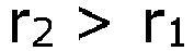
- r 0 1 / 1 / r 1 + 1 / r 2 is preferably from 20 to 80 mm, and more preferably from 40 to 60 mm. Further, it is preferred that r 2 > r 1 or r 2 ⁇ 200 mm is satisfied.
- the curved portion of the substrate has a larger curvature radius r 2 , a lower stress is applied to the substrate, resulting in a lower strain.
- the curved portion preferably has an extremely large curvature radius r 2 .
- FIG. 5 is a schematic diagram of a coating apparatus 10.
- the coating apparatus 10 includes: the coating bar head 1; rollers 11 as substrate transport members that transport the substrate 2; a nozzle 5 as a coating liquid supply member that supplies the coating liquid 3 to the coating bar head 1; and a pump 14 that supplies the coating liquid 3 from a tank 13 to the nozzle 5 through a tube 12.
- a large coating width namely, when the coating bar head has a large length in the longitudinal direction
- each nozzle be each individually detachable, and the distances between the nozzles can be changed, in order to facilitate maintenance, and to obtain a uniform film depending on the physical properties of the coating liquid.
- each nozzle may be provided as one slit.
- the interior of the slit be provided with a liquid reservoir, an uneven structure, a flow channel or the like for achieving liquid supply in a uniform manner.
- the substrate transport members are preferably those that transport the substrate upward from below, and the coating liquid supply member is preferably one that supplies the coating liquid from the upper portion of the coating bar head. This makes gravity to be applied to the meniscus portion, and enables coating at a higher speed. Further, the dripping of the coating liquid can be reduced by supplying the coating liquid from the upper portion of the coating bar head.
- the coating apparatus 10 can further include a member that measures and controls the distance (G or Go) between the coating bar head and the substrate. This member enables to further improve the uniformity of the coating film thickness.
- the coating apparatus 10 can further include a washing member that washes the coating bar head. This allows for washing the coating bar head on a regular basis, and eliminating impurities coming in from an atmosphere and solids precipitated from the coating liquid.
- the washing member may be, for example, a member that sprays or injects a solvent such as water, or a member that applies an ultrasonic wave.
- the coating apparatus 10 can further include a member that collects an excessive coating liquid during coating. This member facilitates the prevention of the backward flow of the coating liquid and the loss of an expensive coating liquid, as well as the prevention of the release of the solvent and the like into the environment.
- Example 1 the step of coating a coating material was carried out as follows, using the coating apparatus 10 shown in FIG. 5 .
- a coating bar head made of SUS 303 and having a length in the coating width direction of 100 mm is prepared, in which, in the cross section of the coating bar head shown in FIG. 3 , the curvature radius r 1 is 40 mm, the angles ⁇ 8 and ⁇ 9 at the bending points are 120° and 90°, respectively, and the length of the curve between the bending points is 25 mm.
- the coating liquid supply member includes five nozzles, whereby the coating liquid is supplied between the coating bar head and the substrate.
- the coating liquid is supplied to the nozzles from one tank through five tubes, by applying a nitrogen pressure to the tank.
- the respective nozzles are provided at intervals of 20 mm.
- Each nozzle is a needle made of stainless steel.
- the object to be coated is a substrate composed of a PET film roll provided with indium tin oxide (ITO) on the side of the surface to be coated.
- ITO indium tin oxide
- the coating bar head is disposed, using an actuator, such that the minimum gap distance between the coating bar head and the PET substrate is 150 ⁇ m.
- a quantity of 40 ⁇ L of the coating liquid is supplied from each nozzle to the coating bar head, to form a meniscus column.
- the coating liquid is coated on the PET substrate to obtain a coating film.
- the moving speed of the PET substrate is controlled constant at 83 mm/s.
- the coating liquid is continuously supplied from the nozzles, and coated to a length of 20 m.
- the film thickness after drying, of the mid-portion of the coating film in a length of 18 m, was measured from the absorption spectrum of the film, and the coating film thickness in a wet state was determined. As a result, the coating film thickness is 10.5 ⁇ 0.1 ⁇ m.
- the coating is carried out in the same manner as in Example 1, except for using a coating bar head made of SUS 303 and having a curvature radius of 10 mm.
- the resulting coating film has a thickness of 11.2 ⁇ 0.3 ⁇ m.
- the coating is carried out in the same manner as in Example 1, except for using a coating bar head made of SUS 303 and having a curvature radius of 100 mm.
- the resulting coating film has a thickness of 9.5 ⁇ 0.3 ⁇ m.
- the coating is carried out in the same manner as in Example 1, except that the minimum gap distance Go is adjusted to 550 ⁇ m, and that 600 ⁇ L of the coating liquid is supplied from each nozzle, to form a meniscus column.
- the resulting coating film has a thickness of 25.0 ⁇ 0.3 ⁇ m.
- the coating is carried out in the same manner as in Example 1, except that a roller having a curvature radius of 200 mm is disposed so as to be opposed to the coating bar head, so that the substrate is made to curve so as to protrude toward the bar head, and that a coating bar head made of SUS 303 and having a curvature radius of 80 mm is used.
- the curvature radius r 0 generated by the above arrangement is 57 mm.
- the resulting coating film has a thickness of 10.0 ⁇ m, and a nonuniformity of less than 0.1 ⁇ m.
- the coating is carried out in the same manner as in Example 1, except for using a coating bar head made of SUS 303 and having a level bottom surface.
- the resulting coating film has a thickness of 12.0 ⁇ 1.0 ⁇ m.
- the coating is carried out in the same manner as in Example 1, except for using a coating bar head made of SUS 303 and having a curvature radius of 8 mm.
- the resulting coating film has a thickness of 13.0 ⁇ 0.7 ⁇ m.
- the coating is carried out in the same manner as in Example 1, except for using a coating bar head made of SUS 303 and having a curvature radius of 110 mm.
- the resulting coating film has a thickness of 9.2 ⁇ 0.6 ⁇ m.
Landscapes
- Engineering & Computer Science (AREA)
- Manufacturing & Machinery (AREA)
- Coating Apparatus (AREA)
- Application Of Or Painting With Fluid Materials (AREA)
Abstract
Description
- Embodiments of the present invention relates to a coating method, a coating bar head and a coating apparatus.
- Organic thin-film solar cells and organic-inorganic hybrid solar cells using organic semiconductors are expected as low-cost solar cells, since inexpensive coating methods can be used for the formation of active layers. In order to achieve the production of organic thin-film solar cells and organic-inorganic hybrid solar cells at low cost, it is required to uniformly coat coating materials for forming organic active layers and other layers. Each layer has a film thickness of from about several nanometers to several hundred nanometers, and it is required to form such an extremely thin layer over a large area, with a high uniformity. For example, meniscus coating is known as one of roll to roll (R2R) coating methods which are capable of coating a very thin layer over large area, at low cost. However, in a conventional meniscus coating method, changes in the coating thickness are more likely to occur, since the distance between a substrate and a coating bar head is more likely to change when coating is performed at a high speed. In cases where a uniform coating thickness is required, as in the case of a common solar cell module, changes in the coating thickness are required to be small. Therefore, an improved meniscus coating method is needed, which allows for obtaining a uniform coating thickness even when coated at a high speed.
- [Patent document 1]
Japanese Patent No. 5981594 - The embodiment of the present invention provides a coating method which enables coating in which changes in coating film thickness is less likely to occur, even when performing meniscus coating at a high speed, and a coating bar head and a coating apparatus which can realize the coating method..
- The coating method according to an embodiment of the present invention is a coating method including:
- supplying a coating liquid between a coating bar head and a substrate to form a meniscus; and
- moving the substrate to form a coating film on the surface of the substrate;
- wherein a cross section of the coating bar head in the direction perpendicular to the longitudinal direction thereof has, on the periphery thereof:
- (a) a curve which is convex outward and which corresponds to a cylindrical surface of the bar head opposed to the substrate; and
- (b) two bending points which are located at both ends of the curve and which correspond to the ends of the cylindrical surface in parallel with the longitudinal direction thereof; and
- wherein the curve in the cross section has a curvature radius of from 10 to 100 mm.
- The coating bar head according to an embodiment of the present invention is a coating bar head for meniscus coating,
- wherein, in the meniscus coating, a coating liquid is supplied between a coating bar head and a substrate to form a meniscus, and the substrate is moved,
- wherein a cross section of the coating bar head in the direction perpendicular to the longitudinal direction thereof has, on the periphery thereof:
- (a) a curve which is convex outward and which corresponds to a cylindrical surface of the bar head opposed to the substrate; and
- (b) two bending points which are located at both ends of the curve and which correspond to the ends of the cylindrical surface in parallel with the longitudinal direction thereof;
- wherein the curve in the cross section has a curvature radius of from 10 to 100 mm.
- The coating apparatus according to an embodiment of the present invention is a coating apparatus including:
- a coating bar head;
- a substrate transport member; and
- a coating liquid supply member;
- wherein these members are disposed such that a meniscus is formed between the bar head and a substrate which is transported by the substrate transport member, when a coating liquid is supplied therebetween;
- wherein a cross section of the coating bar head in the direction perpendicular to the longitudinal direction thereof has, on the periphery thereof:
- (a) a curve which is convex outward and which corresponds to a cylindrical surface of the bar head opposed to the substrate; and
- (b) two bending points which are located at both ends of the curve and which correspond to the ends of the cylindrical surface in parallel with the longitudinal direction thereof;
- wherein the curve in the cross section has a curvature radius of from 10 to 100 mm.
-
-
FIG. 1 is a schematic diagram illustrating a coating method according to an embodiment of the present invention. -
FIG. 2 is a perspective view of a coating bar head embodiment according to an embodiment of the present invention. -
FIG. 3 is a diagram illustrating a cross-sectional shape of the coating bar head. -
FIG. 4 is a cross-sectional view illustrating the relationship among the coating bar head, a planar substrate, and a meniscus formed therebetween. -
FIG. 5 is a schematic diagram illustrating a coating apparatus according to an embodiment of the present invention. - Embodiments will now be explained with reference to the accompanying drawings.
- Configurations common to the embodiments are designated with the same reference numerals, and redundant description will be omitted. Further, respective figures are schematic diagrams for illustrating the embodiments and facilitating the understanding thereof, and the shapes, dimensions, ratios and the like thereof may be different from those of the actual apparatus. The designs of these can be modified as appropriate, in consideration of the following description and known techniques.
-
FIG. 1 is a schematic diagram (cross-sectional view) illustrating a coating method according to an embodiment of the present invention. In the coating method, acoating liquid 3 is supplied between acurved surface 1a of acoating bar head 1, which surface is opposed to asubstrate 2, and thesubstrate 2 which is moving, to continuously form acoating film 6 on asubstrate surface 2a. In the embodiment shown inFIG. 1 , thesubstrate 2 is moving upward from below in the vertical direction, and the curved surface of the coating bar head is disposed so as to be opposed to thesubstrate surface 2a. Then thecoating liquid 3 is supplied from a coatingliquid supply nozzle 5 onto the curved surface of the coating bar head, and ameniscus 4 is formed between the curved surface of the coating bar head and the substrate, due to the surface tension of the coating liquid. - In the present embodiment, the coating bar head has a specific shape.
FIG. 2 shows a perspective view of the coating bar head used in the embodiment;FIG. 3 shows a cross-sectional view in the direction perpendicular to the longitudinal direction of the coating bar head; andFIG. 4 shows a diagram illustrating the state in which thecoating liquid 6 is introduced between thecoating bar head 1 and thesubstrate 2, which is planar, to form themeniscus 4. As shown inFIG. 2 , thesurface 1a of the coating bar head, opposed to the substrate, is a cylindrical surface protruding outward. The cylindrical surface hasridge lines - The shape of the coating bar head can be characterized by the shape of a cross section in the direction perpendicular to the longitudinal direction thereof. The cross section has a shape including, on the periphery thereof:
- (a) a curve which is convex outward and which corresponds to a cylindrical surface of the bar head opposed to the substrate; and
- (b) two bending points which are located at both ends of the curve and which correspond to the ends of the cylindrical surface in parallel with the longitudinal direction thereof. Further, the curve in the cross section has a curvature radius of from 10 to 100 mm.
- The portion of the
coating bar head 1 which corresponds to thesurface 1a opposed to thesubstrate 2 is acurve 7. Thecurve 7 has a shape which is convex outward. Thecurve 7 has bendingpoints ridge lines curve 7 is typically a single circular arc. InFIG. 3 , thecurve 7 is a circular arc having a curvature radius of r1. - The bending points 8a and 8b have bending angles θ8 and θ9, respectively; and the length of the curve between the bending
points 8a and 8b is length d. - The
coating bar head 1 and thesubstrate 2 are disposed at a minimum gap Go; the coating liquid layer to be formed between thecoating bar head 1 and thesubstrate 2 has a maximum thickness G; and the coating liquid layer has a width b. - The present inventors have investigated the relationships between these parameters and the coating film thickness in specific detail, and examined the relationships between the minimum gap Go or the curvature radius r1, and the coating film thickness upon changes in meniscus liquid amount L. As a result, the present inventors have found out, when the
surface 1a of the coating bar head is a cylindrical surface (developable surface) protruding outward, namely, when the portion corresponding to the cylindrical surface, in the cross section of the coating bar head, is a curve convex outward, that changes in the coating film thickness are small in cases where the minimum gap Go changes. When an R2R high-speed coating is performed by meniscus coating, the gap between the coating bar head and the substrate is prone to change due to vibration and the like, but such an influence can be reduced by the use of a coating bar head having a specific shape. - Further, by providing the
ridge lines surface 1a opposed to the substrate, instead of forming a coating bar head in the form of a cylinder, namely, by providing the bending points 8a and 8b on both ends of thecurve 7 in the cross section, the position of the meniscus is stabilized by the pinning effect, as a result of which changes in the coating film thickness are reduced. Since a cylindrical bar is used in a conventional meniscus coating method, the size of the coating apparatus used needs to be increased in the case of using a cylindrical bar having a high curvature. Further, the shape and the position of a nozzle for introducing a coating liquid are restricted, for example, resulting in a poor operability. When the cylindrical surface of the coating bar head has ridge lines at both ends thereof, the size of the bar head can be reduced, and the operability is improved. - The respective parameters will now be described in specific detail.
- The coating film thickness increases when the thickness G and the width b of the coating liquid layer present between the
coating bar head 1 and thesubstrate 2 are increased. Accordingly, when the thickness G and the width b are stable during coating, the resulting coating film has a uniform thickness. However, since the amount of the coating liquid supplied from a nozzle during coating is constant in general, changes in the thickness G or the minimum gap Go leads to changes in the width b, and the coating film thickness is more likely to be nonuniform. In order to minimize the influence of such changes, it is effective to adjust the curvature radius r1. In the present embodiment, the curvature radius ri is from 10 to 100 mm, and preferably from 20 to 80 mm, in order to stabilize the thickness G, the minimum gap Go or the width b, and to form a uniform coating film. Thecurve 7 need not be a single circular arc, and may include a portion having a different curvature radius. In such a case, it is preferred that thecurve 7 have an average curvature radius within the above described range. In such a case, the average curvature radius is referred to as the curvature radius, for convenience. - The minimum gap Go between the coating bar head and the substrate is preferably from 80 to 600 µm, more preferably from 100 to 500 µm, and particularly preferably from 150 to 400 µm. When the minimum gap is smaller than the above described range, streaky unevenness is more likely to occur. When the minimum gap is larger than the above described range, the coating film tends to have too large a thickness, and to have an uneven thickness due to uneven drying. The minimum gap can be controlled using an actuator, a gap ring or the like.
- The angles θ8 and θ9 at the bending points are preferably from 90 to 150°, and more preferably from 100 to 130°. When the angles θ8 and θ9 are smaller than the above described range, it becomes difficult for the coating liquid to return to the
cylindrical surface 1a upon overflowing across the ridge lines. When the angles θ8 and θ9 are larger than the above described range, the effect of stabilizing the position of the coating liquid layer (pinning effect) tends to decrease. It is noted here that the bending points 8a and 8b need not be "points", and may each be, for example, a chamfered or filleted corner. In cases where each bending point is a filleted corner, and when the filleted portion has a large curvature radius, the pinning effect and the like are reduced; accordingly, the curvature radius at each bending point is preferably 1 mm or less. - Further, in the coating bar head shown in
FIG. 3 , the angles θ8 and θ9 are different from each other, and the cross section of the bar head is asymmetrical with respect to the axis extending in the direction perpendicular to the coating surface. However, the cross section of the bar head may be symmetrical. - The length d of the curve between the bending points is preferably from 5 to 30 mm, and more preferably from 7 to 25 mm. When the length d is shorter than the above described range, the resulting meniscus is more likely to be unstable. When the length d is longer than the above described range, the resulting coating film tends to have too large a thickness, and liquid supply tends to be difficult due to an increased size of the bar head.
- The surface of the coating bar head may be a mirror surface, or may be a cloudy surface with unevenness. The cloudy surface tends to have a better wettability with the coating liquid. Further, the surface of the coating bar head may be a combination of a plurality of surfaces having different wettabilities. For example, it is preferred that the
surface 1a onto which the coating liquid is supplied have a good wettability, and the side surfaces, which are in contact with thesurface 1a with theridge lines - Further, the coating bar head may include a dividing groove arranged in the transverse direction thereof. This enables the formation of coating films in the form of strips.
- The moving direction of the substrate is not particularly limited. However, it is preferred that the coating is performed while transporting the substrate upward from below. As shown in
FIG. 1 , for example, gravity is applied to the meniscus portion by moving the substrate upward from below in the vertical direction, and thus a uniform film can be more easily formed even when coated at a high speed. However, the moving direction can be adjusted depending on the configuration of the apparatus and the physical properties of the coating liquid to be used, and is usually within the range of ±30° with respect to the vertical direction. - Although
FIG. 1 shows an example in which the substrate has a plate-like shape, the substrate may be curved so as to protrude toward the side of the coating bar head. In other words, by providing a roller or the like on the side of the substrate opposite to the coating bar head, the substrate can be made to curve such that the substrate surface protrudes toward the side of the coating bar head, at the portion where the meniscus is formed. - In this case, when the curvature radius of the curve of the coating bar head is defined as r1, and the curvature radius of the curved portion of the substrate is defined as r2, r0 represented by the following formula:


- When the curved portion of the substrate has a larger curvature radius r2, a lower stress is applied to the substrate, resulting in a lower strain. When the substrate includes a fragile film, the curved portion preferably has an extremely large curvature radius r2.
-
FIG. 5 is a schematic diagram of acoating apparatus 10. Thecoating apparatus 10 includes: thecoating bar head 1;rollers 11 as substrate transport members that transport thesubstrate 2; anozzle 5 as a coating liquid supply member that supplies thecoating liquid 3 to thecoating bar head 1; and apump 14 that supplies thecoating liquid 3 from atank 13 to thenozzle 5 through atube 12. In cases where the coating is performed over a large coating width, namely, when the coating bar head has a large length in the longitudinal direction, it is desirable to provide a plurality of nozzles arranged in parallel in the longitudinal direction of the coating bar head. It is preferred that the nozzles be each individually detachable, and the distances between the nozzles can be changed, in order to facilitate maintenance, and to obtain a uniform film depending on the physical properties of the coating liquid. Alternatively, each nozzle may be provided as one slit. In this case, it is preferred that the interior of the slit be provided with a liquid reservoir, an uneven structure, a flow channel or the like for achieving liquid supply in a uniform manner. - The substrate transport members are preferably those that transport the substrate upward from below, and the coating liquid supply member is preferably one that supplies the coating liquid from the upper portion of the coating bar head. This makes gravity to be applied to the meniscus portion, and enables coating at a higher speed. Further, the dripping of the coating liquid can be reduced by supplying the coating liquid from the upper portion of the coating bar head.
- The
coating apparatus 10 can further include a member that measures and controls the distance (G or Go) between the coating bar head and the substrate. This member enables to further improve the uniformity of the coating film thickness. - The
coating apparatus 10 can further include a washing member that washes the coating bar head. This allows for washing the coating bar head on a regular basis, and eliminating impurities coming in from an atmosphere and solids precipitated from the coating liquid. Specifically, the washing member may be, for example, a member that sprays or injects a solvent such as water, or a member that applies an ultrasonic wave. - The
coating apparatus 10 can further include a member that collects an excessive coating liquid during coating. This member facilitates the prevention of the backward flow of the coating liquid and the loss of an expensive coating liquid, as well as the prevention of the release of the solvent and the like into the environment. - In Example 1, the step of coating a coating material was carried out as follows, using the
coating apparatus 10 shown inFIG. 5 . First, a coating bar head made of SUS 303 and having a length in the coating width direction of 100 mm is prepared, in which, in the cross section of the coating bar head shown inFIG. 3 , the curvature radius r1 is 40 mm, the angles θ8 and θ9 at the bending points are 120° and 90°, respectively, and the length of the curve between the bending points is 25 mm. - To 1 mL of monochlorobenzene, 8 mg of PTB7 ([poly{4,8-bis[(2-ethylhexyl)oxy]benzo[1,2-b:4,5-b']dithiophen e-2,6-diyl-1t-alt-3-fluoro-2-[(2-ethylhexyl)carbonyl]thieno[3,4-b]thiophene-4,6-diyl}]/ p-type semiconductor), and 12 mg of PC70BM ([6,6]phenyl-C71-butyric acid methyl ester/ n-type semiconductor) are dispersed, to prepare a coating liquid, which is a material for forming an organic active layer of a solar cell. The coating liquid supply member includes five nozzles, whereby the coating liquid is supplied between the coating bar head and the substrate. The coating liquid is supplied to the nozzles from one tank through five tubes, by applying a nitrogen pressure to the tank. The respective nozzles are provided at intervals of 20 mm. Each nozzle is a needle made of stainless steel. The object to be coated is a substrate composed of a PET film roll provided with indium tin oxide (ITO) on the side of the surface to be coated. The coating bar head is disposed, using an actuator, such that the minimum gap distance between the coating bar head and the PET substrate is 150 µm. A quantity of 40 µL of the coating liquid is supplied from each nozzle to the coating bar head, to form a meniscus column. While adjusting the angles of the nozzles and the gap distance, the coating liquid is coated on the PET substrate to obtain a coating film. The moving speed of the PET substrate is controlled constant at 83 mm/s. The coating liquid is continuously supplied from the nozzles, and coated to a length of 20 m. The film thickness after drying, of the mid-portion of the coating film in a length of 18 m, was measured from the absorption spectrum of the film, and the coating film thickness in a wet state was determined. As a result, the coating film thickness is 10.5 ± 0.1 µm.
- The coating is carried out in the same manner as in Example 1, except for using a coating bar head made of SUS 303 and having a curvature radius of 10 mm. The resulting coating film has a thickness of 11.2 ± 0.3 µm.
- The coating is carried out in the same manner as in Example 1, except for using a coating bar head made of SUS 303 and having a curvature radius of 100 mm. The resulting coating film has a thickness of 9.5 ± 0.3 µm.
- The coating is carried out in the same manner as in Example 1, except that the minimum gap distance Go is adjusted to 550 µm, and that 600 µL of the coating liquid is supplied from each nozzle, to form a meniscus column. The resulting coating film has a thickness of 25.0 ± 0.3 µm.
- The coating is carried out in the same manner as in Example 1, except that a roller having a curvature radius of 200 mm is disposed so as to be opposed to the coating bar head, so that the substrate is made to curve so as to protrude toward the bar head, and that a coating bar head made of SUS 303 and having a curvature radius of 80 mm is used. The curvature radius r0 generated by the above arrangement is 57 mm. The resulting coating film has a thickness of 10.0 µm, and a nonuniformity of less than 0.1 µm.
- The coating is carried out in the same manner as in Example 1, except for using a coating bar head made of SUS 303 and having a level bottom surface. The resulting coating film has a thickness of 12.0 ± 1.0 µm.
- The coating is carried out in the same manner as in Example 1, except for using a coating bar head made of SUS 303 and having a curvature radius of 8 mm. The resulting coating film has a thickness of 13.0 ± 0.7 µm.
- The coating is carried out in the same manner as in Example 1, except for using a coating bar head made of SUS 303 and having a curvature radius of 110 mm. The resulting coating film has a thickness of 9.2 ± 0.6 µm.
- While several embodiments of the present invention have been described, these embodiments have been presented by way of example only, and are not intended to limit the scope of the inventions. These novel embodiments can be implemented in a variety of other forms, and various omissions, substitutions and changes can be made without departing from the spirit of the inventions. These embodiments and modifications thereof are included in the scope and spirit of the invention, and are included in the invention described in the claims and their equivalents.
-
- 1
- coating bar head
- 2
- substrate
- 3
- coating material
- 4
- meniscus
- 5
- nozzle
- 6
- coating film
- 7
- curve
- 8
- bending point
- 9
- bending point
- 10
- coating apparatus
- 11
- roller
- 12
- tube
- 13
- tank
- 14
- pump
Claims (20)
- A coating method comprising:supplying a coating liquid between a coating bar head and a substrate to form a meniscus; andmoving said substrate to form a coating film on a surface of said substrate;wherein a cross section of said coating bar head in the direction perpendicular to the longitudinal direction thereof has, on the periphery thereof:(a) a curve which is convex outward and which corresponds to a cylindrical surface of said bar head opposed to said substrate; and(b) two bending points which are located at both ends of the curve and which correspond to the ends of said cylindrical surface in parallel with the longitudinal direction thereof;
andwherein the curve in the cross section has a curvature radius of from 10 to 100 mm. - The coating method according to claim 1, wherein the curve is a circular arc.
- The coating method according to claim 1 or 2, wherein the minimum interval between said coating bar head and said substrate is from 80 to 600 µm.
- The coating method according to any one of claims 1 to 3, wherein at least one of the two bending points has a bending angle of from 90 to 150°.
- The coating method according to any one of claims 1 to 4, wherein the curve between the two bending points has a length of from 5 to 30 mm.
- The coating method according to any one of claims 1 to 5,wherein said substrate is curved so as to protrude toward said coating bar head, at the portion thereof where the meniscus is formed; andwherein, when the curvature radius of the curve in the cross section of said coating bar head is defined as r1, and the curvature radius of the curved portion of said substrate is defined as r2, r0 represented by the following formula:

- The coating method according to claim 6, wherein


- The coating method according to any one of claims 1 to 7, wherein said coating bar head is fixed horizontally, and said substrate is transported upward from below.
- The coating method according to claim 8, wherein said coating liquid is supplied from the upper portion of said coating bar head.
- A coating bar head for meniscus coating,wherein, in the meniscus coating, a coating liquid is supplied between a coating bar head and a substrate to form a meniscus, and said substrate is moved,wherein a cross section of said coating bar head in the direction perpendicular to the longitudinal direction thereof has, on the periphery thereof:(a) a curve which is convex outward and which corresponds to a cylindrical surface of said bar head opposed to said substrate; and(b) two bending points which are located at both ends of the curve and which correspond to the ends of said cylindrical surface in parallel with the longitudinal direction thereof;
andwherein the curve in the cross section has a curvature radius of from 10 to 100 mm. - The coating bar head according to claim 10, wherein at least one of the two bending points has a bending angle of from 90 to 150°.
- The coating bar head d according to claim 10 or 11, wherein the curve between the two bending points has a length of from 5 to 30 mm.
- A coating apparatus comprising:a coating bar head;a substrate transport member; anda coating liquid supply member;wherein these members are disposed such that a meniscus is formed between said bar head and a substrate which is transported by said substrate transport member, when a coating liquid is supplied therebetween;wherein a cross section of said coating bar head in the direction perpendicular to the longitudinal direction thereof has, on the periphery thereof:(a) a curve which is convex outward and which corresponds to a cylindrical surface of said bar head opposed to said substrate; and(b) two bending points which are located at both ends of the curve and which correspond to the ends of said cylindrical surface in parallel with the longitudinal direction thereof;
andwherein the curve in the cross section has a curvature radius of from 10 to 100 mm. - The coating apparatus according to claim 13,wherein said substrate is curved so as to protrude toward said coating bar head, at the portion thereof where the meniscus is formed; andwherein, when the curvature radius of the curve in the cross section of said coating bar head is defined as r1, and the curvature radius of the curved portion of said substrate is defined as r2, r0 represented by the following formula:

- The coating apparatus according to claim 14, wherein


- The coating apparatus according to any one of claims 13 to 15, wherein said coating bar head is fixed horizontally, and said substrate transport member transports said substrate upward from below.
- The coating apparatus according to claim 16, wherein a coating liquid supply nozzle is disposed at the upper portion of said coating bar head.
- The coating apparatus according to any one of claims 13 to 17, further comprising a means that measures and controls the distance between said coating bar head and said substrate.
- The coating apparatus according to any one of claims 13 to 16, further comprising a washing member that washes said coating bar head.
- The coating apparatus according to any one of claims 13 to 19, further comprising a member that collects an excessive coating liquid during coating.
Applications Claiming Priority (1)
| Application Number | Priority Date | Filing Date | Title |
|---|---|---|---|
| PCT/JP2019/035560 WO2021048924A1 (en) | 2019-09-10 | 2019-09-10 | Coating method, coating bar head, and coating device |
Publications (2)
| Publication Number | Publication Date |
|---|---|
| EP4029614A1 true EP4029614A1 (en) | 2022-07-20 |
| EP4029614A4 EP4029614A4 (en) | 2023-06-14 |
Family
ID=74866292
Family Applications (1)
| Application Number | Title | Priority Date | Filing Date |
|---|---|---|---|
| EP19941774.2A Pending EP4029614A4 (en) | 2019-09-10 | 2019-09-10 | COATING PROCESS, COATING ROD HEAD AND COATING DEVICE |
Country Status (5)
| Country | Link |
|---|---|
| US (1) | US11623238B2 (en) |
| EP (1) | EP4029614A4 (en) |
| JP (1) | JP7093891B2 (en) |
| CN (1) | CN112789120B (en) |
| WO (1) | WO2021048924A1 (en) |
Families Citing this family (3)
| Publication number | Priority date | Publication date | Assignee | Title |
|---|---|---|---|---|
| EP4302882A4 (en) * | 2021-03-04 | 2025-01-29 | Kabushiki Kaisha Toshiba | Coating apparatus and coating method |
| EP4184601B1 (en) * | 2021-11-18 | 2024-07-17 | IMEC vzw | A method and an apparatus for applying thin film material onto a substrate |
| JP7714830B2 (en) * | 2023-03-08 | 2025-07-29 | 株式会社東芝 | Coating device and coating method |
Family Cites Families (22)
| Publication number | Priority date | Publication date | Assignee | Title |
|---|---|---|---|---|
| US3496012A (en) * | 1967-02-13 | 1970-02-17 | Mead Corp | Coating apparatus and method |
| JPS58205561A (en) * | 1982-05-25 | 1983-11-30 | Fuji Photo Film Co Ltd | Method and device for coating |
| JPS6089827A (en) * | 1983-10-22 | 1985-05-20 | Konishiroku Photo Ind Co Ltd | Method and apparatus of flat coating film |
| JPH0640990B2 (en) * | 1985-11-15 | 1994-06-01 | 富士写真フイルム株式会社 | Application method |
| DE68906416T2 (en) * | 1988-02-17 | 1993-09-09 | Konishiroku Photo Ind | COATING APPARATUS. |
| US5097792A (en) * | 1989-03-20 | 1992-03-24 | Konica Corporation | Coating apparatus |
| JP2684486B2 (en) | 1992-02-13 | 1997-12-03 | 富士写真フイルム株式会社 | Coating device |
| JP2684487B2 (en) * | 1992-02-28 | 1997-12-03 | 富士写真フイルム株式会社 | Coating method of magnetic recording medium |
| CA2133266A1 (en) * | 1993-10-29 | 1995-04-30 | Hans-Jurgen Meissner | Slot coating die configuration |
| US20020121239A1 (en) * | 1996-04-10 | 2002-09-05 | Tonazzi Juan C. Lopez | Devices and methods for applying liquid coatings to substrates |
| US5718429A (en) * | 1997-02-06 | 1998-02-17 | Keller, Jr.; Claude Emery | Method of combining a casino game with a game of skill |
| JP2000229262A (en) | 1999-02-09 | 2000-08-22 | Fuji Photo Film Co Ltd | Coating method |
| JP2000279860A (en) * | 1999-03-29 | 2000-10-10 | Sony Corp | Coating method and coating device |
| EP1870169B1 (en) | 2005-04-12 | 2013-01-16 | Toray Industries, Inc. | Coater of electric insulating sheet and method for producing electric insulating sheet with coated film |
| JP5176284B2 (en) | 2005-04-12 | 2013-04-03 | 東レ株式会社 | Electrical insulating sheet coating apparatus and method for producing coated insulating sheet |
| TWI288030B (en) * | 2005-12-30 | 2007-10-11 | Ind Tech Res Inst | Method for improving the homogeneity of coating layers |
| JP2008136884A (en) | 2006-11-29 | 2008-06-19 | Fujifilm Corp | Bar coating apparatus and method |
| JP2013202455A (en) * | 2012-03-27 | 2013-10-07 | Lintec Corp | Coating method |
| JP5981589B1 (en) * | 2015-02-26 | 2016-08-31 | 株式会社東芝 | Coating method and coating apparatus |
| JP6239548B2 (en) * | 2015-03-18 | 2017-11-29 | 株式会社東芝 | Coating apparatus and coating method |
| JP5897749B1 (en) * | 2015-03-18 | 2016-03-30 | 株式会社東芝 | Coating method and coating apparatus |
| JP5981594B1 (en) | 2015-03-24 | 2016-08-31 | 株式会社東芝 | Coating method and coating apparatus |
-
2019
- 2019-09-10 EP EP19941774.2A patent/EP4029614A4/en active Pending
- 2019-09-10 WO PCT/JP2019/035560 patent/WO2021048924A1/en not_active Ceased
- 2019-09-10 CN CN201980056521.XA patent/CN112789120B/en active Active
- 2019-09-10 JP JP2021510477A patent/JP7093891B2/en active Active
-
2021
- 2021-02-26 US US17/186,789 patent/US11623238B2/en active Active
Also Published As
| Publication number | Publication date |
|---|---|
| US11623238B2 (en) | 2023-04-11 |
| JP7093891B2 (en) | 2022-06-30 |
| CN112789120A (en) | 2021-05-11 |
| US20210178420A1 (en) | 2021-06-17 |
| CN112789120B (en) | 2023-07-28 |
| EP4029614A4 (en) | 2023-06-14 |
| WO2021048924A1 (en) | 2021-03-18 |
| JPWO2021048924A1 (en) | 2021-10-14 |
Similar Documents
| Publication | Publication Date | Title |
|---|---|---|
| US11623238B2 (en) | Coating method, coating bar head and coating apparatus | |
| US20210408378A1 (en) | Coating process and coating apparatus usable for device formation | |
| US20240399406A1 (en) | Coating device, meniscus head, and coating method | |
| US8534222B2 (en) | Delivery unit, coating apparatus, and coating method | |
| US12233432B2 (en) | Coating apparatus and coating method | |
| JP6683820B2 (en) | Membrane manufacturing method | |
| US20250187034A1 (en) | Coating head, coating device, and coating method | |
| JP2011054386A (en) | Method for manufacturing organic el display | |
| WO2024185086A1 (en) | Coating apparatus and coating method | |
| US8733271B2 (en) | Method and apparatus for continuous coating | |
| CN104511396A (en) | Coating apparatus | |
| CN105457836A (en) | Application apparatus and application method | |
| US20250178021A1 (en) | Coating device and coating method | |
| KR20070007921A (en) | Support guide | |
| JP2004141698A (en) | Method of forming resist pattern, method of manufacturing solar cell using the same, and resist pattern forming apparatus | |
| KR101416978B1 (en) | Apparatus for align and system for in-line deposition | |
| CN109309158A (en) | Preparation method of patterned organic film layer, preparation method of array substrate | |
| JP2007275818A (en) | Bar coating method and apparatus | |
| KR102511233B1 (en) | Thin film disposition apparatus | |
| JP3383093B2 (en) | Applicator for coating liquid on substrate | |
| JP2007296503A (en) | Die, die system coating apparatus and coating method |
Legal Events
| Date | Code | Title | Description |
|---|---|---|---|
| STAA | Information on the status of an ep patent application or granted ep patent |
Free format text: STATUS: UNKNOWN |
|
| STAA | Information on the status of an ep patent application or granted ep patent |
Free format text: STATUS: THE INTERNATIONAL PUBLICATION HAS BEEN MADE |
|
| PUAI | Public reference made under article 153(3) epc to a published international application that has entered the european phase |
Free format text: ORIGINAL CODE: 0009012 |
|
| STAA | Information on the status of an ep patent application or granted ep patent |
Free format text: STATUS: REQUEST FOR EXAMINATION WAS MADE |
|
| 17P | Request for examination filed |
Effective date: 20210224 |
|
| AK | Designated contracting states |
Kind code of ref document: A1 Designated state(s): AL AT BE BG CH CY CZ DE DK EE ES FI FR GB GR HR HU IE IS IT LI LT LU LV MC MK MT NL NO PL PT RO RS SE SI SK SM TR |
|
| DAV | Request for validation of the european patent (deleted) | ||
| DAX | Request for extension of the european patent (deleted) | ||
| REG | Reference to a national code |
Ref country code: DE Ref legal event code: R079 Free format text: PREVIOUS MAIN CLASS: B05D0001260000 Ipc: B05D0001280000 |
|
| A4 | Supplementary search report drawn up and despatched |
Effective date: 20230516 |
|
| RIC1 | Information provided on ipc code assigned before grant |
Ipc: B05C 11/02 20060101ALN20230511BHEP Ipc: H10K 30/30 20230101ALN20230511BHEP Ipc: B05C 5/02 20060101ALN20230511BHEP Ipc: H10K 71/12 20230101ALI20230511BHEP Ipc: B05C 1/04 20060101ALI20230511BHEP Ipc: B05D 1/42 20060101ALI20230511BHEP Ipc: B05D 1/28 20060101AFI20230511BHEP |