EP4029610A1 - Continuous centrifugal dehydrating apparatus - Google Patents
Continuous centrifugal dehydrating apparatus Download PDFInfo
- Publication number
- EP4029610A1 EP4029610A1 EP21876744.0A EP21876744A EP4029610A1 EP 4029610 A1 EP4029610 A1 EP 4029610A1 EP 21876744 A EP21876744 A EP 21876744A EP 4029610 A1 EP4029610 A1 EP 4029610A1
- Authority
- EP
- European Patent Office
- Prior art keywords
- basket
- gas
- slurry
- external case
- dewatering device
- Prior art date
- Legal status (The legal status is an assumption and is not a legal conclusion. Google has not performed a legal analysis and makes no representation as to the accuracy of the status listed.)
- Granted
Links
Images


Classifications
-
- B—PERFORMING OPERATIONS; TRANSPORTING
- B04—CENTRIFUGAL APPARATUS OR MACHINES FOR CARRYING-OUT PHYSICAL OR CHEMICAL PROCESSES
- B04B—CENTRIFUGES
- B04B1/00—Centrifuges with rotary bowls provided with solid jackets for separating predominantly liquid mixtures with or without solid particles
- B04B1/20—Centrifuges with rotary bowls provided with solid jackets for separating predominantly liquid mixtures with or without solid particles discharging solid particles from the bowl by a conveying screw coaxial with the bowl axis and rotating relatively to the bowl
-
- B—PERFORMING OPERATIONS; TRANSPORTING
- B04—CENTRIFUGAL APPARATUS OR MACHINES FOR CARRYING-OUT PHYSICAL OR CHEMICAL PROCESSES
- B04B—CENTRIFUGES
- B04B3/00—Centrifuges with rotary bowls in which solid particles or bodies become separated by centrifugal force and simultaneous sifting or filtering
- B04B3/02—Centrifuges with rotary bowls in which solid particles or bodies become separated by centrifugal force and simultaneous sifting or filtering discharging solid particles from the bowl by means coaxial with the bowl axis and moving to and fro, i.e. push-type centrifuges
-
- B—PERFORMING OPERATIONS; TRANSPORTING
- B04—CENTRIFUGAL APPARATUS OR MACHINES FOR CARRYING-OUT PHYSICAL OR CHEMICAL PROCESSES
- B04B—CENTRIFUGES
- B04B1/00—Centrifuges with rotary bowls provided with solid jackets for separating predominantly liquid mixtures with or without solid particles
- B04B1/10—Centrifuges with rotary bowls provided with solid jackets for separating predominantly liquid mixtures with or without solid particles with discharging outlets in the plane of the maximum diameter of the bowl
- B04B1/12—Centrifuges with rotary bowls provided with solid jackets for separating predominantly liquid mixtures with or without solid particles with discharging outlets in the plane of the maximum diameter of the bowl with continuous discharge
-
- B—PERFORMING OPERATIONS; TRANSPORTING
- B04—CENTRIFUGAL APPARATUS OR MACHINES FOR CARRYING-OUT PHYSICAL OR CHEMICAL PROCESSES
- B04B—CENTRIFUGES
- B04B11/00—Feeding, charging, or discharging bowls
- B04B11/04—Periodical feeding or discharging; Control arrangements therefor
-
- B—PERFORMING OPERATIONS; TRANSPORTING
- B04—CENTRIFUGAL APPARATUS OR MACHINES FOR CARRYING-OUT PHYSICAL OR CHEMICAL PROCESSES
- B04B—CENTRIFUGES
- B04B15/00—Other accessories for centrifuges
- B04B15/08—Other accessories for centrifuges for ventilating or producing a vacuum in the centrifuge
-
- B—PERFORMING OPERATIONS; TRANSPORTING
- B04—CENTRIFUGAL APPARATUS OR MACHINES FOR CARRYING-OUT PHYSICAL OR CHEMICAL PROCESSES
- B04B—CENTRIFUGES
- B04B15/00—Other accessories for centrifuges
- B04B15/12—Other accessories for centrifuges for drying or washing the separated solid particles
-
- B—PERFORMING OPERATIONS; TRANSPORTING
- B04—CENTRIFUGAL APPARATUS OR MACHINES FOR CARRYING-OUT PHYSICAL OR CHEMICAL PROCESSES
- B04B—CENTRIFUGES
- B04B7/00—Elements of centrifuges
- B04B7/08—Rotary bowls
- B04B7/12—Inserts, e.g. armouring plates
- B04B7/16—Sieves or filters
-
- B—PERFORMING OPERATIONS; TRANSPORTING
- B04—CENTRIFUGAL APPARATUS OR MACHINES FOR CARRYING-OUT PHYSICAL OR CHEMICAL PROCESSES
- B04B—CENTRIFUGES
- B04B9/00—Drives specially designed for centrifuges; Arrangement or disposition of transmission gearing; Suspending or balancing rotary bowls
- B04B9/10—Control of the drive; Speed regulating
-
- F—MECHANICAL ENGINEERING; LIGHTING; HEATING; WEAPONS; BLASTING
- F26—DRYING
- F26B—DRYING SOLID MATERIALS OR OBJECTS BY REMOVING LIQUID THEREFROM
- F26B17/00—Machines or apparatus for drying materials in loose, plastic, or fluidised form, e.g. granules, staple fibres, with progressive movement
- F26B17/10—Machines or apparatus for drying materials in loose, plastic, or fluidised form, e.g. granules, staple fibres, with progressive movement with movement performed by fluid currents, e.g. issuing from a nozzle, e.g. pneumatic, flash, vortex or entrainment dryers
-
- F—MECHANICAL ENGINEERING; LIGHTING; HEATING; WEAPONS; BLASTING
- F26—DRYING
- F26B—DRYING SOLID MATERIALS OR OBJECTS BY REMOVING LIQUID THEREFROM
- F26B21/00—Arrangements for supplying or controlling air or other gases for drying solid materials or objects
- F26B21/40—Arrangements for supplying or controlling air or other gases for drying solid materials or objects using gases other than air
-
- F—MECHANICAL ENGINEERING; LIGHTING; HEATING; WEAPONS; BLASTING
- F26—DRYING
- F26B—DRYING SOLID MATERIALS OR OBJECTS BY REMOVING LIQUID THEREFROM
- F26B25/00—Details of general application not covered by group F26B21/00 or F26B23/00
- F26B25/008—Seals, locks, e.g. gas barriers or air curtains, for drying enclosures
-
- F—MECHANICAL ENGINEERING; LIGHTING; HEATING; WEAPONS; BLASTING
- F26—DRYING
- F26B—DRYING SOLID MATERIALS OR OBJECTS BY REMOVING LIQUID THEREFROM
- F26B5/00—Drying solid materials or objects by processes not involving the application of heat
- F26B5/08—Drying solid materials or objects by processes not involving the application of heat by centrifugal treatment
-
- F—MECHANICAL ENGINEERING; LIGHTING; HEATING; WEAPONS; BLASTING
- F26—DRYING
- F26B—DRYING SOLID MATERIALS OR OBJECTS BY REMOVING LIQUID THEREFROM
- F26B2200/00—Drying processes and machines for solid materials characterised by the specific requirements of the drying goods
- F26B2200/18—Sludges, e.g. sewage, waste, industrial processes, cooling towers
Definitions
- the present invention relates to a continuous centrifugal dewatering device (or a continuous centrifugal spin dryer), and more particularly, to a continuous centrifugal dewatering device having improved dewatering efficiency of a polymer slurry.
- a process of producing polymers includes polymerization, agglomeration, dewatering, and drying processes, and a polymer slurry produced through the polymerization and agglomeration processes contains a large amount of moisture.
- a hot air drying method is generally used, which, however, incurs high energy cost, and thus, removing moisture of the polymer slurry as much as possible to lower a moisture content thereof during the dewatering process prior to performing the drying process is the key to improving economical efficiency of the processes.
- a slurry cake having a low moisture content by removing a portion of moisture from the polymer slurry during the dewatering process may undergo a drying process so as to be obtained as a powdery polymer solid having a moisture content of less than 1%.
- a centrifugal dewatering device During the dewatering process, it is common to go through a centrifugal dewatering device to primarily remove moisture, and among the centrifugal dewatering devices, a pusher-type continuous centrifugal dewatering device capable of performing a continuous process is used to increase productivity.
- the continuous centrifugal dewatering device of the related art simply dewaters using only centrifugal force, the dewatering efficiency is not excellent to lead to a problem that high energy cost is consumed during the drying process.
- the dewatering efficiency is not excellent to lead to a problem that high energy cost is consumed during the drying process.
- moisture contained in the pores increases to lower the dewatering efficiency.
- An object of the present invention is to provide a continuous centrifugal dewatering device capable of improving dewatering efficiency of a slurry by using pressure and a blowing effect of a gas, as well as centrifugal force, by supplying the gas together with the slurry.
- a continuous centrifugal dewatering device includes: an external case having an internal space; a feed supply pipe to which a slurry as a mixture of a solid and a liquid is supplied; a basket provided inside the external case, configured to receive a first gas and the slurry provided thereto and rotate to apply centrifugal force to the slurry; a plurality of holes formed in the basket and configured to discharge a liquid filtered from the slurry to the outside of the basket; a pusher plate provided inside the basket and configured to discharge a slurry cake attached to an inner circumferential surface of the basket to the outside of the external case; a non-contact seal configured to prevent the first gas from flowing into a space between the external case and the basket; and a gas inlet to which a second gas, which flows in a reverse direction with respect to a flow direction of the first gas flowing to the space between the external case and the basket, is supplied.
- a gas is supplied together with a slurry to improve the dewatering efficiency of the slurry by not only centrifugal force but also pressure and a blowing effect of the gas.
- slurry may refer to a mixture of solid and liquid or a suspension in which fine solid particles are suspended in a liquid
- a "polymer slurry” may refer to a mixture of a solvent used in a polymerization and a solid such as a polymer generated by a polymerization or a suspension in which the solids are suspended in the solvent.
- slurry cake may refer to a solid after dewatering and filtration of the slurry.
- a continuous centrifugal dewatering device includes: an external case 100 having an internal space; a feed supply pipe 200 to which a slurry as a mixture of a solid and a liquid is supplied; a basket 300 provided inside the external case 100, configured to receive a first gas and the slurry provided thereto and rotate to apply centrifugal force to the slurry; a plurality of holes 310 formed in the basket 300 and configured to discharge a liquid filtered from the slurry to the outside of the basket 300; a pusher plate 400 provided inside the basket 300 and configured to discharge a slurry cake 10 attached to an inner circumferential surface of the basket 300 by centrifugal force to the outside of the external case 100; a non-contact seal 500 configured to prevent the first gas from flowing into a space between the external case 100 and the basket 300; and a gas inlet 600 to which a second gas, which flows in a reverse direction with respect to a flow direction of the first gas
- a process of producing a polymer includes polymerization, agglomeration, dewatering and drying processes, and a polymer slurry produced through the polymerization and agglomeration processes contains a large amount of moisture.
- a hot air drying method is generally used, which, however, incurs high energy cost, and thus, removing moisture of the polymer slurry as much as possible to lower a moisture content thereof during the dewatering process prior to performing the drying process is the key to improving economical efficiency of the processes.
- a slurry cake having a low moisture content by removing a portion of moisture from the polymer slurry during the dewatering process may undergo a drying process so as to be obtained as a powdery polymer solid having a moisture content of less than 1%.
- a centrifugal dewatering device During the dewatering process, it is common to go through a centrifugal dewatering device to primarily remove moisture, and among the centrifugal dewatering devices, a pusher-type continuous centrifugal dewatering device capable of performing a continuous process is used to increase productivity.
- the continuous centrifugal dewatering device of the related art simply dewaters using only centrifugal force, the dewatering efficiency is not excellent to lead to a problem that high energy cost is consumed during the drying process.
- the dewatering efficiency is not excellent to lead to a problem that high energy cost is consumed during the drying process.
- moisture contained in the pores increases to lower the dewatering efficiency.
- the present invention provides a continuous centrifugal dewatering device capable of improving dewatering performance of a slurry by supplying the slurry together with a gas. That is, by using the continuous centrifugal dewatering device according to the present invention during a dewatering process, it is possible to obtain a slurry having a moisture content as low as possible, thereby reducing energy consumed in a subsequent drying process.
- the continuous centrifugal dewatering device may be a continuous centrifugal dewatering device in which a slurry containing a solid and a liquid and a first gas are supplied together to improve dewatering efficiency of the slurry using pressure and blowing effect of the first gas, as well as centrifugal force.
- the continuous centrifugal dewatering device may be a device for applying centrifugal force to the slurry to separate a liquid contained in the slurry by a difference in specific gravity and generate and discharge the slurry cake 10 without the liquid.
- a first gas may be additionally supplied to provide an additional dewatering effect to the slurry by pressure and blowing effect of the gas.
- the continuous centrifugal dewatering device may include an external case 100 having an internal space.
- the external case 100 may include a liquid outlet 110 through which a liquid filtered from the slurry is discharged, a slurry cake outlet 120 through which the slurry cake 10 is discharged, and a gas outlet 130 through which the first gas is discharged.
- the continuous centrifugal dewatering device may include a feed supply pipe 200 to which a slurry of a mixture of solid and water is supplied.
- the feed supply pipe 200 may extend into the inside of the basket 300 to be described later to supply the slurry into the inside of the basket 300.
- the slurry may be formed by mixing a solid and a liquid, and as a specific example, the slurry may be a polymer slurry produced by a polymerization.
- the continuous centrifugal dewatering device may include the basket 300 provided inside the external case 100, receiving the first gas and the slurry supplied thereto, and rotating to apply centrifugal force to the slurry.
- the basket 300 may have a cylindrical shape.
- the basket 300 may apply centrifugal force to the slurry, while rotating, the slurry is attached to an inner circumferential surface of the basket 300 by centrifugal force and a liquid is filtered from the slurry through the plurality of holes 310 to be described later, and the filtered liquid may be discharged to the outside of the basket 300.
- the basket 300 may include a rotation driving unit 320 for performing a rotational motion of the basket 300.
- the rotation driving unit 320 may include a power unit (not shown) and a power transmission unit (not shown), but the rotation driving unit is not limited thereto and may include any unit capable of performing a rotational motion of the basket 300.
- the continuous centrifugal dewatering device may include the plurality of holes 310 formed in the basket 300 and discharging the liquid filtered from the slurry to the outside of the basket 300.
- a plurality of holes 310 may be formed along a circumference of the basket 300.
- the plurality may refer to one or more. That is, the plurality of holes 310 may refer to one or more holes.
- the plurality of holes 310 may include holes having a diameter through which the liquid filtered from the slurry passes and the slurry cake 10 attached to the inner circumferential surface of the basket 300 does not pass. Accordingly, the slurry cake 10 may not be discharged through the plurality of holes 310 and only the liquid may be discharged.
- the liquid may be filtered from the slurry through the plurality of holes 310 included in the basket 300, and the filtered liquid may be discharged to the outside of the basket 300, that is, a space between the basket 300 and the external case 100.
- the continuous centrifugal dewatering device may include the pusher plate 400 provided inside the basket 300 and discharging the slurry cake 10 attached to the inner circumferential surface of the basket 300 to the outside of the external case 100.
- the continuous centrifugal dewatering device may filter the liquid from the slurry by centrifugal force to form the slurry cake 10 in which the liquid is filtered out.
- centrifugal force may be applied to the slurry by a rotational motion of the basket 300, and accordingly, the slurry may be attached to the inner circumferential surface of the basket 300 by a force distributed in a direction of the inner circumferential surface of the basket 300, and, at the same time, the liquid included in the slurry may be discharged through the plurality of holes 310 included in the basket 300.
- the slurry cake 10 without a liquid may be attached to the inner circumferential surface of the basket 300 without being discharged to the outside of the basket 300.
- a reciprocating motion of the pusher plate 400 may be performed to discharge the slurry cake 10 attached to the inner circumferential surface of the basket 300 to the outside of the external case 100, that is, to the outside of the continuous centrifugal dewatering device.
- the liquid included in the slurry supplied through the feed supply pipe 200 may be filtered out, i.e., separated, by centrifugal force due to the rotational motion of the basket 300, and thus, the slurry cake 10 attached to and formed on the inner circumferential surface of the basket 300 may be discharged to the outside of the continuous centrifugal dewatering device by the reciprocating motion of the pusher plate 400.
- the liquid may be discharged to the outside of the external case 100, i.e., to the outside of the continuous centrifugal dewatering device through the liquid outlet 110 included in the external case 100.
- the slurry cake 10 may be discharged to the outside of the external case 100, i.e., to the outside of the continuous centrifugal dewatering device, through the slurry cake outlet 120 included in the external case 100 by the reciprocating motion of the pusher plate 400.
- the pusher plate 400 may perform a continuous reciprocating motion, and thus the slurry cake 10 may be continuously discharged.
- the pusher plate 400 may include a pusher system 410 for reciprocating the pusher plate 400.
- the pusher system 410 may include a power unit (not shown) and a power transmission unit (not shown), but is not limited thereto, and may include any unit capable of performing a reciprocating motion of the pusher plate 400.
- the continuous centrifugal dewatering device may further include a dispersing plate 210 provided inside the basket 300 and dispersing the slurry supplied from the feed supply pipe 200 in the basket 300.
- the dispersing plate 210 may serve to uniformly disperse the slurry supplied from the feed supply pipe 200 in the inside of the basket 300, while being reflected by the dispersing plate 210. As such, since the slurry is uniformly dispersed inside the basket 300, the slurry to which centrifugal force is applied may be attached to the inner circumferential surface of the basket 300 with a uniform thickness, thereby maximally improving dewatering performance.
- the dispersing plate 210 may further include a support 220 connected to the feed supply pipe 200 to support the dispersing plate 210. That is, the dispersing plate 210 may be fixed to the inside of the basket 300 by the support 220 connected to the feed supply pipe 200.
- the continuous centrifugal dewatering device may additionally supply a first gas to the inside of the basket 300.
- the continuous centrifugal dewatering device may further include a gas supply pipe 700 for supplying the first gas to the inside of the basket 300.
- the first gas may be mixed with the slurry to form a mixed feed so as to be supplied to the feed supply pipe 200 or may be independently supplied through the gas supply pipe 700.
- the first gas may be mixed with the slurry supplied to the feed supply pipe 200 by the rotational motion of the basket 300.
- the gas supply pipe 700 may extend into the inside of the basket 300 to supply the first gas to the inside of the basket 300, and the first gas supplied to the inside of the basket 300 may be discharged to the outside through the plurality of holes 310 included in the basket 300 or through the gas outlet 130 included in the external case 100 after passing through the space between the external case 100 and the basket 300.
- the gas supply pipe 700 may include a plurality of pores formed in a longitudinal direction.
- the first gas may be uniformly supplied to the inside of the basket 300 through the plurality of pores, and thus, the first gas may be uniformly mixed with the slurry.
- the dewatering efficiency of the slurry may be improved by using the pressure and blowing effect of the first gas as well as centrifugal force.
- the dewatering effect by blowing may be added to the slurry cake 10 in the process in which the first gas passes through the slurry cake 10 attached to the inner circumferential surface of the basket 300 by centrifugal force and is discharged through the plurality of holes 310 of the basket 300.
- the continuous centrifugal dewatering device may include the non-contact seal 500 preventing the first gas from flowing into the space between the external case 100 and the basket 300.
- the first gas supplied into the basket 300 may pass through the space between the external case 100 and the basket 300 in addition to the plurality of holes 310 included in the basket 300, and then be discharged to the outside through the gas outlet 130 included in the external case 100.
- the non-contact seal 500 is provided in the space between the external case 100 and the basket 300 to prevent the first gas from flowing into the space between the external case 100 and the basket 300, thereby increasing a flow rate of the first gas passing through the slurry cake 10. Accordingly, there is an effect of improving the dewatering effect acting on the slurry cake 10.
- the non-contact seal 500 may be attached to the external case 100 and spaced apart from the basket 300 or may be attached to the basket 300 and spaced apart from the external case 100. As such, when a space 1 exists between the non-contact seal 500 and the basket 300, frictional contact between the non-contact seal 500 and the basket 300 due to the rotational motion of the basket 300 may be reduced to prevent a deterioration of durability, thereby improving long-term operation characteristics of the continuous centrifugal dewatering device.
- FIG. 3 showing a cross-sectional view in an A-B direction of the continuous centrifugal dewatering device according to the present invention shown in FIG. 1 , since the space 1 exists between the non-contact seal 500 and the basket 300, frictional contact between the non-contact seal 500 and the basket 300 due to the rotational motion of the basket 300 may be prevented.
- FIG. 4 shows an embodiment in which the non-contact seal 500 is attached to the external case 100.
- the non-contact seal 500 may be attached to the external case 100 or the basket 300 by coupling using a bolt 510 or the like.
- a portion of the external case 100 may be divided, the non-contact seal 500 may be inserted into the portion of the divided external case 100, and the divided external case 100 may be coupled using the bolt 510 or the like, thereby fixing the non-contact seal 500, but an attaching method of the non-contact seal 500 is not limited thereto.
- the non-contact seal 500 may be provided, for example, in a labyrinth shape and may be formed of white metal, brass pins, nickel pins, or the like. As shown in FIG. 4 , the non-contact seal 500 may have a sharp shape in a direction adjacent to a contact portion, so that even if the non-contact seal 500 comes into contact with a component of the continuous centrifugal dewatering device, only the contact portion of the non-contact seal 500 may melt to prevent damage of the external case 100 or the basket 300 that may come into contact with the non-contact seal 500 due to frictional contact.
- the continuous centrifugal dewatering device may include the gas inlet 600 through which a second gas, which flows in a reverse direction with respect to a flow direction of the first gas flowing to the space between the external case 100 and the basket 300, is supplied.
- a flow path of the first gas may be changed into the inside of the basket 300 by supplying the second gas flowing in the reverse direction with respect to the flow direction of the first gas.
- the gas inlet 600 may be provided in the form of one or more pores formed along the circumference of the basket 300, but is not limited thereto.
- a flow rate at which the first gas flows into the space between the external case 100 and the basket 300 may be reduced by 80% or more, 90% or more, or 95% or more, compared to the case where the second gas is not supplied.
- the second gas supplied through the gas inlet 600 may pass through the slurry cake 10 attached to the inner circumferential surface of the basket 300 and be discharged through the plurality of holes 310 included in the basket 300.
- a dewatering effect by blowing may be added to the slurry cake 10. That is, by further imparting the dewatering effect based on blowing to the slurry cake 10 with the second gas as well as the first gas described above, there is an effect of further lowering the moisture content of the slurry cake 10.
- the second gas discharged through the plurality of holes 310 included in the basket 300 may be discharged to the outside through the gas outlet 130 included in the external case 100.
- the first gas and the second gas may be the same or different from each other, and may independently be air in the atmosphere or an inert gas.
- the first gas and the second gas may be the same or different from each other and may independently include one or more inert gases selected from the group consisting of nitrogen, neon, helium, and argon.
- inert gases selected from the group consisting of nitrogen, neon, helium, and argon.
- the first gas and the second gas may each include an inert gas, thereby preventing an additional side reaction of the polymer.
- the gas is used for dewatering of the slurry, and a gas having moisture content of 20% or less, 10% or less, or 5% or less may be used.
- the first gas and the second gas discharged to the outside of the external case 100 may be re-introduced into the inside of the basket 300. That is, the first gas and the second gas discharged to the outside of the basket 300 may be discharged to the outside of the external case 100 through the gas outlet 130, and then re-introduced into the inside of the basket 300.
- the first gas and the second gas may be re-introduced through the feed supply pipe 200 or the gas supply pipe 700.
- a pipe connecting the gas outlet 130 and the feed supply pipe 200 may be further provided, and in a case in which the first gas and the second gas are re-introduced through the gas supply pipe 700, a pipe connecting the gas outlet 130 and the gas supply pipe 700 may be further provided.
- the liquid discharged through the liquid outlet 110 and the slurry cake 10 discharged through the slurry cake outlet 120 may have a downward flow inside the basket 300 due to a difference in density with the first gas, and the first gas or the second gas discharged through the gas outlet 130 may have an upward flow inside the basket 300 due to a difference in density between the liquid and the slurry cake 10.
- the liquid outlet 110 and the slurry cake outlet 120 may be included at a lower portion of the external case 100, and the gas outlet 130 may be included at an upper portion of the external case 100.
- the "upper portion” may refer to a portion corresponding to a height of 50% or higher, 70% or higher, or 80% or higher from a total height of the external case 100
- the “lower portion” may refer to a portion corresponding to a height less than 50%, less than 30%, or less than 10% from the total height of the external case 100.
- the continuous centrifugal dewatering device includes the non-contact seal 500 and the gas inlet 600 for preventing the first gas from flowing into the space between the external case 100 and the basket 300 while the first gas is supplied, the dewatering performance of the slurry may be further improved, compared to the continuous centrifugal dewatering device of the related art.
- a dewatering rate of moisture contained in the pores of polymer particles with developed pores may be increased to obtain the slurry cake 10 having a moisture content less than 10%, less than 6%, or less than 3% from the polymer slurry. Accordingly, energy consumed during a subsequent drying process may be reduced.
- the continuous centrifugal dewatering device according to the present invention is illustrated and shown in the description and drawings, but the descriptions and drawings show only the essential components for understanding the present invention, and a process and device not described or illustrated other than the process and device shown in the descriptions and drawings may be appropriately applied and used to implement the continuous centrifugal dewatering device according to the present invention.
Landscapes
- Engineering & Computer Science (AREA)
- Mechanical Engineering (AREA)
- General Engineering & Computer Science (AREA)
- Health & Medical Sciences (AREA)
- Life Sciences & Earth Sciences (AREA)
- Molecular Biology (AREA)
- Centrifugal Separators (AREA)
Abstract
Description
- The present application claims priority to
Korean Patent Application No. 10-2020-0128011, filed on October 5, 2020 - The present invention relates to a continuous centrifugal dewatering device (or a continuous centrifugal spin dryer), and more particularly, to a continuous centrifugal dewatering device having improved dewatering efficiency of a polymer slurry.
- In general, a process of producing polymers includes polymerization, agglomeration, dewatering, and drying processes, and a polymer slurry produced through the polymerization and agglomeration processes contains a large amount of moisture.
- During the drying process, a hot air drying method is generally used, which, however, incurs high energy cost, and thus, removing moisture of the polymer slurry as much as possible to lower a moisture content thereof during the dewatering process prior to performing the drying process is the key to improving economical efficiency of the processes.
- As described above, a slurry cake having a low moisture content by removing a portion of moisture from the polymer slurry during the dewatering process may undergo a drying process so as to be obtained as a powdery polymer solid having a moisture content of less than 1%.
- During the dewatering process, it is common to go through a centrifugal dewatering device to primarily remove moisture, and among the centrifugal dewatering devices, a pusher-type continuous centrifugal dewatering device capable of performing a continuous process is used to increase productivity.
- However, since the continuous centrifugal dewatering device of the related art simply dewaters using only centrifugal force, the dewatering efficiency is not excellent to lead to a problem that high energy cost is consumed during the drying process. In addition, when pores are developed inside polymer particles in the polymer slurry, moisture contained in the pores increases to lower the dewatering efficiency.
- Therefore, there is a need to develop a continuous centrifugal dewatering device capable of solving the above problems.
- An object of the present invention is to provide a continuous centrifugal dewatering device capable of improving dewatering efficiency of a slurry by using pressure and a blowing effect of a gas, as well as centrifugal force, by supplying the gas together with the slurry.
- In one general aspect, a continuous centrifugal dewatering device includes: an external case having an internal space; a feed supply pipe to which a slurry as a mixture of a solid and a liquid is supplied; a basket provided inside the external case, configured to receive a first gas and the slurry provided thereto and rotate to apply centrifugal force to the slurry; a plurality of holes formed in the basket and configured to discharge a liquid filtered from the slurry to the outside of the basket; a pusher plate provided inside the basket and configured to discharge a slurry cake attached to an inner circumferential surface of the basket to the outside of the external case; a non-contact seal configured to prevent the first gas from flowing into a space between the external case and the basket; and a gas inlet to which a second gas, which flows in a reverse direction with respect to a flow direction of the first gas flowing to the space between the external case and the basket, is supplied.
- In the continuous centrifugal dewatering device according to the present invention, a gas is supplied together with a slurry to improve the dewatering efficiency of the slurry by not only centrifugal force but also pressure and a blowing effect of the gas.
- That is, by using the continuous centrifugal dewatering device according to the present invention during a dewatering process, it is possible to obtain a slurry having a moisture content as low as possible, thereby reducing energy consumed in a subsequent drying process.
-
-
FIG. 1 is a longitudinal cross-sectional view of a continuous centrifugal dewatering device according to an embodiment of the present invention. -
FIG. 2 is a longitudinal cross-sectional view of a continuous centrifugal dewatering device further including a gas supply pipe according to an embodiment of the present invention. -
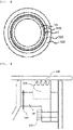
FIG. 3 is a cross-sectional view of a continuous centrifugal dewatering device according to an embodiment of the present invention. -
FIG. 4 is an enlarged view showing a coupling relationship between a non-contact seal and an external case according to an embodiment of the present invention. - Terms and words used in the present specification and claims are not to be construed as a general or dictionary meaning but are to be construed as meaning and concepts meeting the technical ideas of the present invention based on a principle that the inventors may appropriately define the concepts of terms in order to describe their own inventions in the best mode.
- In the present invention, the term "slurry" may refer to a mixture of solid and liquid or a suspension in which fine solid particles are suspended in a liquid, and a "polymer slurry" may refer to a mixture of a solvent used in a polymerization and a solid such as a polymer generated by a polymerization or a suspension in which the solids are suspended in the solvent.
- In the present invention, the term "slurry cake" may refer to a solid after dewatering and filtration of the slurry.
- Hereinafter, the present invention will be described in more detail with reference to the following drawings in order to help understand the present invention.
- According to the present invention, a continuous centrifugal dewatering device is provided. The continuous centrifugal dewatering device includes: an
external case 100 having an internal space; afeed supply pipe 200 to which a slurry as a mixture of a solid and a liquid is supplied; abasket 300 provided inside theexternal case 100, configured to receive a first gas and the slurry provided thereto and rotate to apply centrifugal force to the slurry; a plurality ofholes 310 formed in thebasket 300 and configured to discharge a liquid filtered from the slurry to the outside of thebasket 300; apusher plate 400 provided inside thebasket 300 and configured to discharge aslurry cake 10 attached to an inner circumferential surface of thebasket 300 by centrifugal force to the outside of theexternal case 100; anon-contact seal 500 configured to prevent the first gas from flowing into a space between theexternal case 100 and thebasket 300; and a gas inlet 600 to which a second gas, which flows in a reverse direction with respect to a flow direction of the first gas flowing to the space between theexternal case 100 and thebasket 300, is supplied. - In general, a process of producing a polymer includes polymerization, agglomeration, dewatering and drying processes, and a polymer slurry produced through the polymerization and agglomeration processes contains a large amount of moisture.
- During the drying process, a hot air drying method is generally used, which, however, incurs high energy cost, and thus, removing moisture of the polymer slurry as much as possible to lower a moisture content thereof during the dewatering process prior to performing the drying process is the key to improving economical efficiency of the processes.
- As described above, a slurry cake having a low moisture content by removing a portion of moisture from the polymer slurry during the dewatering process may undergo a drying process so as to be obtained as a powdery polymer solid having a moisture content of less than 1%.
- During the dewatering process, it is common to go through a centrifugal dewatering device to primarily remove moisture, and among the centrifugal dewatering devices, a pusher-type continuous centrifugal dewatering device capable of performing a continuous process is used to increase productivity.
- However, since the continuous centrifugal dewatering device of the related art simply dewaters using only centrifugal force, the dewatering efficiency is not excellent to lead to a problem that high energy cost is consumed during the drying process. In addition, when pores are developed inside polymer particles in the polymer slurry, moisture contained in the pores increases to lower the dewatering efficiency.
- Therefore, the present invention provides a continuous centrifugal dewatering device capable of improving dewatering performance of a slurry by supplying the slurry together with a gas. That is, by using the continuous centrifugal dewatering device according to the present invention during a dewatering process, it is possible to obtain a slurry having a moisture content as low as possible, thereby reducing energy consumed in a subsequent drying process.
- According to an embodiment of the present invention, the continuous centrifugal dewatering device according to the present invention may be a continuous centrifugal dewatering device in which a slurry containing a solid and a liquid and a first gas are supplied together to improve dewatering efficiency of the slurry using pressure and blowing effect of the first gas, as well as centrifugal force.
- As a specific example, the continuous centrifugal dewatering device may be a device for applying centrifugal force to the slurry to separate a liquid contained in the slurry by a difference in specific gravity and generate and discharge the
slurry cake 10 without the liquid. As a more specific example, in addition to the slurry, a first gas may be additionally supplied to provide an additional dewatering effect to the slurry by pressure and blowing effect of the gas. - According to an embodiment of the present invention, the continuous centrifugal dewatering device according to the present invention may include an
external case 100 having an internal space. - The
external case 100 may include aliquid outlet 110 through which a liquid filtered from the slurry is discharged, aslurry cake outlet 120 through which theslurry cake 10 is discharged, and agas outlet 130 through which the first gas is discharged. - According to an embodiment of the present invention, the continuous centrifugal dewatering device according to the present invention may include a
feed supply pipe 200 to which a slurry of a mixture of solid and water is supplied. - The
feed supply pipe 200 may extend into the inside of thebasket 300 to be described later to supply the slurry into the inside of thebasket 300. As described above, the slurry may be formed by mixing a solid and a liquid, and as a specific example, the slurry may be a polymer slurry produced by a polymerization. - According to an embodiment of the present invention, the continuous centrifugal dewatering device according to the present invention may include the
basket 300 provided inside theexternal case 100, receiving the first gas and the slurry supplied thereto, and rotating to apply centrifugal force to the slurry. - For example, the
basket 300 may have a cylindrical shape. As a more specific example, thebasket 300 may apply centrifugal force to the slurry, while rotating, the slurry is attached to an inner circumferential surface of thebasket 300 by centrifugal force and a liquid is filtered from the slurry through the plurality ofholes 310 to be described later, and the filtered liquid may be discharged to the outside of thebasket 300. - The
basket 300 may include arotation driving unit 320 for performing a rotational motion of thebasket 300. For example, therotation driving unit 320 may include a power unit (not shown) and a power transmission unit (not shown), but the rotation driving unit is not limited thereto and may include any unit capable of performing a rotational motion of thebasket 300. - According to an embodiment of the present invention, the continuous centrifugal dewatering device according to the present invention may include the plurality of
holes 310 formed in thebasket 300 and discharging the liquid filtered from the slurry to the outside of thebasket 300. - For example, when the
basket 300 has a cylindrical shape, a plurality ofholes 310 may be formed along a circumference of thebasket 300. In this case, the plurality may refer to one or more. That is, the plurality ofholes 310 may refer to one or more holes. - The plurality of
holes 310 may include holes having a diameter through which the liquid filtered from the slurry passes and theslurry cake 10 attached to the inner circumferential surface of thebasket 300 does not pass. Accordingly, theslurry cake 10 may not be discharged through the plurality ofholes 310 and only the liquid may be discharged. - As described above, the liquid may be filtered from the slurry through the plurality of
holes 310 included in thebasket 300, and the filtered liquid may be discharged to the outside of thebasket 300, that is, a space between thebasket 300 and theexternal case 100. - According to an embodiment of the present invention, the continuous centrifugal dewatering device according to the present invention may include the
pusher plate 400 provided inside thebasket 300 and discharging theslurry cake 10 attached to the inner circumferential surface of thebasket 300 to the outside of theexternal case 100. - The continuous centrifugal dewatering device may filter the liquid from the slurry by centrifugal force to form the
slurry cake 10 in which the liquid is filtered out. As a specific example, centrifugal force may be applied to the slurry by a rotational motion of thebasket 300, and accordingly, the slurry may be attached to the inner circumferential surface of thebasket 300 by a force distributed in a direction of the inner circumferential surface of thebasket 300, and, at the same time, the liquid included in the slurry may be discharged through the plurality ofholes 310 included in thebasket 300. Here, theslurry cake 10 without a liquid may be attached to the inner circumferential surface of thebasket 300 without being discharged to the outside of thebasket 300. - In this manner, a reciprocating motion of the
pusher plate 400 may be performed to discharge theslurry cake 10 attached to the inner circumferential surface of thebasket 300 to the outside of theexternal case 100, that is, to the outside of the continuous centrifugal dewatering device. - For example, the liquid included in the slurry supplied through the
feed supply pipe 200 may be filtered out, i.e., separated, by centrifugal force due to the rotational motion of thebasket 300, and thus, theslurry cake 10 attached to and formed on the inner circumferential surface of thebasket 300 may be discharged to the outside of the continuous centrifugal dewatering device by the reciprocating motion of thepusher plate 400. - Here, after the liquid is discharged to the space between the
basket 300 and theexternal case 100, the liquid may be discharged to the outside of theexternal case 100, i.e., to the outside of the continuous centrifugal dewatering device through theliquid outlet 110 included in theexternal case 100. - In addition, the
slurry cake 10 may be discharged to the outside of theexternal case 100, i.e., to the outside of the continuous centrifugal dewatering device, through theslurry cake outlet 120 included in theexternal case 100 by the reciprocating motion of thepusher plate 400. Thepusher plate 400 may perform a continuous reciprocating motion, and thus theslurry cake 10 may be continuously discharged. - The
pusher plate 400 may include apusher system 410 for reciprocating thepusher plate 400. For example, thepusher system 410 may include a power unit (not shown) and a power transmission unit (not shown), but is not limited thereto, and may include any unit capable of performing a reciprocating motion of thepusher plate 400. - According to an embodiment of the present invention, the continuous centrifugal dewatering device according to the present invention may further include a dispersing
plate 210 provided inside thebasket 300 and dispersing the slurry supplied from thefeed supply pipe 200 in thebasket 300. - The dispersing
plate 210 may serve to uniformly disperse the slurry supplied from thefeed supply pipe 200 in the inside of thebasket 300, while being reflected by the dispersingplate 210. As such, since the slurry is uniformly dispersed inside thebasket 300, the slurry to which centrifugal force is applied may be attached to the inner circumferential surface of thebasket 300 with a uniform thickness, thereby maximally improving dewatering performance. - The dispersing
plate 210 may further include asupport 220 connected to thefeed supply pipe 200 to support the dispersingplate 210. That is, the dispersingplate 210 may be fixed to the inside of thebasket 300 by thesupport 220 connected to thefeed supply pipe 200. - According to an embodiment of the present invention, the continuous centrifugal dewatering device according to the present invention may additionally supply a first gas to the inside of the
basket 300. - In addition, the continuous centrifugal dewatering device according to the present invention may further include a
gas supply pipe 700 for supplying the first gas to the inside of thebasket 300. - Accordingly, the first gas may be mixed with the slurry to form a mixed feed so as to be supplied to the
feed supply pipe 200 or may be independently supplied through thegas supply pipe 700. Here, even if the first gas is independently supplied through thegas supply pipe 700, the first gas may be mixed with the slurry supplied to thefeed supply pipe 200 by the rotational motion of thebasket 300. - The
gas supply pipe 700 may extend into the inside of thebasket 300 to supply the first gas to the inside of thebasket 300, and the first gas supplied to the inside of thebasket 300 may be discharged to the outside through the plurality ofholes 310 included in thebasket 300 or through thegas outlet 130 included in theexternal case 100 after passing through the space between theexternal case 100 and thebasket 300. - As a specific example, the
gas supply pipe 700 may include a plurality of pores formed in a longitudinal direction. In this case, the first gas may be uniformly supplied to the inside of thebasket 300 through the plurality of pores, and thus, the first gas may be uniformly mixed with the slurry. - As such, when the first gas is additionally supplied in addition to the slurry supplied to the inside of the
basket 300, the dewatering efficiency of the slurry may be improved by using the pressure and blowing effect of the first gas as well as centrifugal force. - Specifically, when the first gas is supplied to the inside of the
basket 300, pressure of the first gas may act on the slurry dispersed in the inner circumferential direction of thebasket 300 by centrifugal force to further improve the operation of filtering the liquid from the slurry. In addition, the dewatering effect by blowing may be added to theslurry cake 10 in the process in which the first gas passes through theslurry cake 10 attached to the inner circumferential surface of thebasket 300 by centrifugal force and is discharged through the plurality ofholes 310 of thebasket 300. - According to an embodiment of the present invention, the continuous centrifugal dewatering device according to the present invention may include the
non-contact seal 500 preventing the first gas from flowing into the space between theexternal case 100 and thebasket 300. - As described above, the first gas supplied into the
basket 300 may pass through the space between theexternal case 100 and thebasket 300 in addition to the plurality ofholes 310 included in thebasket 300, and then be discharged to the outside through thegas outlet 130 included in theexternal case 100. In this case, a problem arises in that the dewatering effect may be reduced due to the blowing that occurs in the process in which the first gas passes through theslurry cake 10 attached to the inner circumferential surface of thebasket 300 and is discharged through the plurality ofholes 310 of thebasket 300. - In order to solve this problem, in the present invention, the
non-contact seal 500 is provided in the space between theexternal case 100 and thebasket 300 to prevent the first gas from flowing into the space between theexternal case 100 and thebasket 300, thereby increasing a flow rate of the first gas passing through theslurry cake 10. Accordingly, there is an effect of improving the dewatering effect acting on theslurry cake 10. - The
non-contact seal 500 may be attached to theexternal case 100 and spaced apart from thebasket 300 or may be attached to thebasket 300 and spaced apart from theexternal case 100. As such, when aspace 1 exists between thenon-contact seal 500 and thebasket 300, frictional contact between thenon-contact seal 500 and thebasket 300 due to the rotational motion of thebasket 300 may be reduced to prevent a deterioration of durability, thereby improving long-term operation characteristics of the continuous centrifugal dewatering device. In addition, when a space exists between thenon-contact seal 500 and theexternal case 100, frictional contact between thenon-contact seal 500 and theexternal case 100 due to the rotational motion of thebasket 300 may be reduced to prevent a deterioration of durability, thereby improving long-term operation characteristics of the continuous centrifugal dewatering device. - For example, referring to
FIG. 3 showing a cross-sectional view in an A-B direction of the continuous centrifugal dewatering device according to the present invention shown inFIG. 1 , since thespace 1 exists between thenon-contact seal 500 and thebasket 300, frictional contact between thenon-contact seal 500 and thebasket 300 due to the rotational motion of thebasket 300 may be prevented. - In addition,
FIG. 4 shows an embodiment in which thenon-contact seal 500 is attached to theexternal case 100. - Referring to
FIG. 4 , thenon-contact seal 500 may be attached to theexternal case 100 or thebasket 300 by coupling using abolt 510 or the like. In a specific example, a portion of theexternal case 100 may be divided, thenon-contact seal 500 may be inserted into the portion of the dividedexternal case 100, and the dividedexternal case 100 may be coupled using thebolt 510 or the like, thereby fixing thenon-contact seal 500, but an attaching method of thenon-contact seal 500 is not limited thereto. - The
non-contact seal 500 may be provided, for example, in a labyrinth shape and may be formed of white metal, brass pins, nickel pins, or the like. As shown inFIG. 4 , thenon-contact seal 500 may have a sharp shape in a direction adjacent to a contact portion, so that even if thenon-contact seal 500 comes into contact with a component of the continuous centrifugal dewatering device, only the contact portion of thenon-contact seal 500 may melt to prevent damage of theexternal case 100 or thebasket 300 that may come into contact with thenon-contact seal 500 due to frictional contact. - According to an embodiment of the present invention, the continuous centrifugal dewatering device according to the present invention may include the
gas inlet 600 through which a second gas, which flows in a reverse direction with respect to a flow direction of the first gas flowing to the space between theexternal case 100 and thebasket 300, is supplied. - Even if the
non-contact seal 500 is provided in the space between theexternal case 100 and thebasket 300, the space exists to be separated from thebasket 300 or theexternal case 100 as described above. Therefore, in order to prevent the first gas from flowing into the space, a flow path of the first gas may be changed into the inside of thebasket 300 by supplying the second gas flowing in the reverse direction with respect to the flow direction of the first gas. - For example, when the
basket 300 has a cylindrical shape, thegas inlet 600 may be provided in the form of one or more pores formed along the circumference of thebasket 300, but is not limited thereto. - In this manner, when the second gas is supplied through the
gas inlet 600, a flow rate at which the first gas flows into the space between theexternal case 100 and thebasket 300 may be reduced by 80% or more, 90% or more, or 95% or more, compared to the case where the second gas is not supplied. - The second gas supplied through the
gas inlet 600 may pass through theslurry cake 10 attached to the inner circumferential surface of thebasket 300 and be discharged through the plurality ofholes 310 included in thebasket 300. In this process, a dewatering effect by blowing may be added to theslurry cake 10. That is, by further imparting the dewatering effect based on blowing to theslurry cake 10 with the second gas as well as the first gas described above, there is an effect of further lowering the moisture content of theslurry cake 10. - The second gas discharged through the plurality of
holes 310 included in thebasket 300 may be discharged to the outside through thegas outlet 130 included in theexternal case 100. - According to an embodiment of the present invention, the first gas and the second gas may be the same or different from each other, and may independently be air in the atmosphere or an inert gas.
- As a specific example, the first gas and the second gas may be the same or different from each other and may independently include one or more inert gases selected from the group consisting of nitrogen, neon, helium, and argon. As such, when the first gas and the second gas each include an inert gas, explosion or fire due to contact with oxygen may be prevented.
- As a more specific example, when the slurry is a polymer slurry, the first gas and the second gas may each include an inert gas, thereby preventing an additional side reaction of the polymer.
- In addition, the gas is used for dewatering of the slurry, and a gas having moisture content of 20% or less, 10% or less, or 5% or less may be used.
- According to an embodiment of the present invention, the first gas and the second gas discharged to the outside of the
external case 100 may be re-introduced into the inside of thebasket 300. That is, the first gas and the second gas discharged to the outside of thebasket 300 may be discharged to the outside of theexternal case 100 through thegas outlet 130, and then re-introduced into the inside of thebasket 300. - Here, the first gas and the second gas may be re-introduced through the
feed supply pipe 200 or thegas supply pipe 700. In order for the first gas and the second gas to be re-introduced through thefeed supply pipe 200, a pipe connecting thegas outlet 130 and thefeed supply pipe 200 may be further provided, and in a case in which the first gas and the second gas are re-introduced through thegas supply pipe 700, a pipe connecting thegas outlet 130 and thegas supply pipe 700 may be further provided. - According to an embodiment of the present invention, the liquid discharged through the
liquid outlet 110 and theslurry cake 10 discharged through theslurry cake outlet 120 may have a downward flow inside thebasket 300 due to a difference in density with the first gas, and the first gas or the second gas discharged through thegas outlet 130 may have an upward flow inside thebasket 300 due to a difference in density between the liquid and theslurry cake 10. - Accordingly, the
liquid outlet 110 and theslurry cake outlet 120 may be included at a lower portion of theexternal case 100, and thegas outlet 130 may be included at an upper portion of theexternal case 100. Here, the "upper portion" may refer to a portion corresponding to a height of 50% or higher, 70% or higher, or 80% or higher from a total height of theexternal case 100, and the "lower portion" may refer to a portion corresponding to a height less than 50%, less than 30%, or less than 10% from the total height of theexternal case 100. - According to an embodiment of the present invention, since the continuous centrifugal dewatering device according to the present invention includes the
non-contact seal 500 and thegas inlet 600 for preventing the first gas from flowing into the space between theexternal case 100 and thebasket 300 while the first gas is supplied, the dewatering performance of the slurry may be further improved, compared to the continuous centrifugal dewatering device of the related art. - In particular, when the slurry is a polymer slurry, a dewatering rate of moisture contained in the pores of polymer particles with developed pores may be increased to obtain the
slurry cake 10 having a moisture content less than 10%, less than 6%, or less than 3% from the polymer slurry. Accordingly, energy consumed during a subsequent drying process may be reduced. - As described above, the continuous centrifugal dewatering device according to the present invention is illustrated and shown in the description and drawings, but the descriptions and drawings show only the essential components for understanding the present invention, and a process and device not described or illustrated other than the process and device shown in the descriptions and drawings may be appropriately applied and used to implement the continuous centrifugal dewatering device according to the present invention.
Claims (10)
a gas supply pipe configured to supply the first gas into the basket.
a dispersing plate provided inside the basket and configured to disperse the slurry supplied from the feed supply pipe to an inside of the basket.
Applications Claiming Priority (2)
| Application Number | Priority Date | Filing Date | Title |
|---|---|---|---|
| KR1020200128011A KR102646571B1 (en) | 2020-10-05 | 2020-10-05 | Continuous centrifugal dehydrator |
| PCT/KR2021/011078 WO2022075582A1 (en) | 2020-10-05 | 2021-08-20 | Continuous centrifugal dehydrating apparatus |
Publications (3)
| Publication Number | Publication Date |
|---|---|
| EP4029610A1 true EP4029610A1 (en) | 2022-07-20 |
| EP4029610A4 EP4029610A4 (en) | 2023-01-18 |
| EP4029610B1 EP4029610B1 (en) | 2025-07-02 |
Family
ID=81126593
Family Applications (1)
| Application Number | Title | Priority Date | Filing Date |
|---|---|---|---|
| EP21876744.0A Active EP4029610B1 (en) | 2020-10-05 | 2021-08-20 | Continuous centrifugal dehydrating apparatus |
Country Status (6)
| Country | Link |
|---|---|
| US (1) | US12623234B2 (en) |
| EP (1) | EP4029610B1 (en) |
| JP (1) | JP7395233B2 (en) |
| KR (1) | KR102646571B1 (en) |
| CN (1) | CN114599453B (en) |
| WO (1) | WO2022075582A1 (en) |
Families Citing this family (1)
| Publication number | Priority date | Publication date | Assignee | Title |
|---|---|---|---|---|
| KR102504657B1 (en) * | 2019-11-18 | 2023-02-27 | 주식회사 엘지화학 | Pressurizing centrifugal dehydrator |
Family Cites Families (32)
| Publication number | Priority date | Publication date | Assignee | Title |
|---|---|---|---|---|
| CH205982A (en) | 1938-12-02 | 1939-07-15 | Ter Meer Gustav Ing Dr | Pusher centrifuge. |
| FR2334420A1 (en) | 1975-12-12 | 1977-07-08 | Dietrich & Cie De | AXIAL THRUST SPINNER |
| JPS5443670U (en) | 1977-09-01 | 1979-03-26 | ||
| DE2909716A1 (en) | 1979-03-13 | 1980-09-18 | Krauss Maffei Ag | DRAWER CENTRIFUGE |
| CH653573A5 (en) | 1981-06-25 | 1986-01-15 | Escher Wyss Ag | DRAWER CENTRIFUGE. |
| DE4010748A1 (en) | 1989-04-13 | 1990-10-25 | Stahl Werner | METHOD FOR OPERATING AN EXTENSION CENTRIFUGE |
| US5401423A (en) | 1991-11-27 | 1995-03-28 | Baker Hughes Incorporated | Feed accelerator system including accelerator disc |
| US5397471A (en) | 1993-08-30 | 1995-03-14 | Tema Systems, Inc. | Self-cleaning scroll and screen centrifuge |
| JPH08192077A (en) | 1995-01-12 | 1996-07-30 | Mitsui Petrochem Ind Ltd | centrifuge |
| JP3313286B2 (en) | 1996-01-17 | 2002-08-12 | 株式会社松本機械製作所 | Centrifugal filtration method and device |
| DE19646038C2 (en) | 1996-11-08 | 1998-08-06 | Heinkel Ind Zentrifugen | Inverting filter centrifuge |
| DE19648511C1 (en) | 1996-11-22 | 1998-04-16 | Heinkel Ind Zentrifugen | Inverted filter centrifuge for separation of solid material-fluid mixture |
| US6159360A (en) * | 1996-11-22 | 2000-12-12 | Heinkel Industriezentrifugen Gmbh & Co. | Invertible filter centrifuge including a solids drier |
| JPH1123152A (en) | 1997-07-04 | 1999-01-26 | Toshiba Corp | Centrifugal thin film dryer and sludge treatment method using the same |
| US6109452A (en) | 1998-06-04 | 2000-08-29 | Baker Hughes Incorporated | Centrifuge with partial wear resistant basket |
| KR20000024471A (en) | 2000-02-12 | 2000-05-06 | 이상호 | Centryfugal separator with reversing filter cloths |
| ES2608852T3 (en) | 2003-04-16 | 2017-04-17 | Ferrum Ag | Multi-phase thrust centrifuge |
| ATE397496T1 (en) * | 2003-04-16 | 2008-06-15 | Ferrum Ag | PUSH CENTRIFUGE WITH ROTATING FUNNEL FOR ACCELERATION OF THE MIXTURE |
| EP1468743A1 (en) | 2003-04-16 | 2004-10-20 | Ferrum AG | Pusher centrifuge |
| KR20060089881A (en) | 2005-02-03 | 2006-08-10 | 주식회사 루펜비아이에프 | Food waste dehydration device |
| JP4824962B2 (en) | 2005-07-25 | 2011-11-30 | 越後製菓株式会社 | Centrifugal dehydrator |
| DE102006009200A1 (en) | 2006-02-22 | 2007-08-30 | Fima Maschinenbau Gmbh | Centrifuge operation in e.g. chemical-, pharmaceutical or food manufacture, comprises drying of cake with local radial influx of drying gas, whilst maintaining rotary speed avoiding cake collapse |
| JP5211082B2 (en) * | 2010-01-15 | 2013-06-12 | 株式会社神鋼環境ソリューション | Filtration drying method |
| JP5475919B1 (en) | 2013-11-01 | 2014-04-16 | 巴工業株式会社 | Sealed decanter centrifuge |
| JP6217416B2 (en) | 2014-01-31 | 2017-10-25 | 株式会社Ihi | Solid-liquid separator |
| JP2015144989A (en) * | 2014-02-03 | 2015-08-13 | 株式会社松本機械製作所 | centrifuge |
| CN203862419U (en) | 2014-05-28 | 2014-10-08 | 中国矿业大学 | Centrifugal filtration dehydration device for fine-grain materials |
| EP3023160B1 (en) | 2014-11-21 | 2020-02-19 | Alfa Laval Corporate AB | A centrifugal separator |
| PL3263222T3 (en) | 2016-06-27 | 2021-01-11 | Alfa Laval Corporate Ab | Centrifugal separator having a ventilation system |
| KR101738388B1 (en) * | 2016-11-15 | 2017-05-29 | (주)동일캔바스엔지니어링 | Centrifugal dehydrator with air nozzle |
| CN107158761A (en) | 2017-06-22 | 2017-09-15 | 合肥通用机械研究院 | A kind of centrifugal dehumidifier for separating gypsum |
| JP6673947B2 (en) * | 2018-01-17 | 2020-04-01 | 月島機械株式会社 | Extrusion type centrifuge and method of operating the same |
-
2020
- 2020-10-05 KR KR1020200128011A patent/KR102646571B1/en active Active
-
2021
- 2021-08-20 US US17/770,417 patent/US12623234B2/en active Active
- 2021-08-20 CN CN202180006131.9A patent/CN114599453B/en active Active
- 2021-08-20 JP JP2022525435A patent/JP7395233B2/en active Active
- 2021-08-20 WO PCT/KR2021/011078 patent/WO2022075582A1/en not_active Ceased
- 2021-08-20 EP EP21876744.0A patent/EP4029610B1/en active Active
Also Published As
| Publication number | Publication date |
|---|---|
| WO2022075582A1 (en) | 2022-04-14 |
| US20220388014A1 (en) | 2022-12-08 |
| EP4029610A4 (en) | 2023-01-18 |
| KR20220045367A (en) | 2022-04-12 |
| CN114599453A (en) | 2022-06-07 |
| US12623234B2 (en) | 2026-05-12 |
| KR102646571B1 (en) | 2024-03-11 |
| JP2023501241A (en) | 2023-01-18 |
| JP7395233B2 (en) | 2023-12-11 |
| CN114599453B (en) | 2024-10-25 |
| EP4029610B1 (en) | 2025-07-02 |
Similar Documents
| Publication | Publication Date | Title |
|---|---|---|
| US5833865A (en) | Sedimentation type solid-liquid separator | |
| EP4029610B1 (en) | Continuous centrifugal dehydrating apparatus | |
| CN109759245B (en) | Centrifugal separation equipment | |
| CN101018601A (en) | Apparatus and method for solid-liquid contact | |
| JP4761216B2 (en) | Two-stage coagulation mixing tank | |
| CN109622946B (en) | Universal suspension granulation method for preparing sintered metal-graphite composite material | |
| EP0629424A1 (en) | Sedimentation type solid-liquid separator | |
| RU2083723C1 (en) | Method of production of graphite bisulfate and reactor for its embodiment | |
| CN203316270U (en) | Centrifugal dehydration device | |
| CN104707541B (en) | The segmented cyclone reaction kettle of homogeneous reaction | |
| CN210386212U (en) | Flat plate loading and unloading centrifuge | |
| JPS59132926A (en) | Separation mechanism of stirring medium | |
| CN212440134U (en) | Multistage continuous countercurrent washing and leaching equipment | |
| CN213912367U (en) | Dispersion disk of micro powder centrifugal spray drying equipment | |
| CN210022510U (en) | High-speed centrifuge for separating various substances by using multi-filter-hole technology | |
| CN109721679B (en) | Preparation method of polyacrylonitrile resin with loose particle structure for carbon fibers | |
| CN218058784U (en) | High efficiency sludge treatment equipment | |
| CN219023443U (en) | Automatic high Wen Guye separator of ejection of compact | |
| CN223697403U (en) | Stirring device for ceramic coating production for small household appliances | |
| CN220802347U (en) | Thallus protein mash separating device and thallus protein production line | |
| CN223175850U (en) | Funnel is used in water paint production convenient to connect | |
| CN217550364U (en) | Dedicated high-efficient filter equipment of tungsten ore production | |
| CN120422351A (en) | Electronic component manufacturing apparatus and electronic component manufacturing method | |
| FI125394B (en) | Process for feeding granular suspended matter in liquid | |
| CN119186302A (en) | Stirring structure, reactor and solid-phase polypeptide synthesis device |
Legal Events
| Date | Code | Title | Description |
|---|---|---|---|
| STAA | Information on the status of an ep patent application or granted ep patent |
Free format text: STATUS: UNKNOWN |
|
| STAA | Information on the status of an ep patent application or granted ep patent |
Free format text: STATUS: THE INTERNATIONAL PUBLICATION HAS BEEN MADE |
|
| PUAI | Public reference made under article 153(3) epc to a published international application that has entered the european phase |
Free format text: ORIGINAL CODE: 0009012 |
|
| STAA | Information on the status of an ep patent application or granted ep patent |
Free format text: STATUS: REQUEST FOR EXAMINATION WAS MADE |
|
| 17P | Request for examination filed |
Effective date: 20220414 |
|
| AK | Designated contracting states |
Kind code of ref document: A1 Designated state(s): AL AT BE BG CH CY CZ DE DK EE ES FI FR GB GR HR HU IE IS IT LI LT LU LV MC MK MT NL NO PL PT RO RS SE SI SK SM TR |
|
| A4 | Supplementary search report drawn up and despatched |
Effective date: 20221220 |
|
| RIC1 | Information provided on ipc code assigned before grant |
Ipc: F26B 5/08 20060101ALI20221214BHEP Ipc: F26B 25/00 20060101ALI20221214BHEP Ipc: F26B 21/14 20060101ALI20221214BHEP Ipc: F26B 17/10 20060101ALI20221214BHEP Ipc: B04B 3/02 20060101ALI20221214BHEP Ipc: B04B 15/12 20060101ALI20221214BHEP Ipc: B04B 15/08 20060101ALI20221214BHEP Ipc: B04B 9/10 20060101ALI20221214BHEP Ipc: B04B 7/16 20060101ALI20221214BHEP Ipc: B04B 1/12 20060101ALI20221214BHEP Ipc: B04B 1/20 20060101AFI20221214BHEP |
|
| DAV | Request for validation of the european patent (deleted) | ||
| DAX | Request for extension of the european patent (deleted) | ||
| GRAP | Despatch of communication of intention to grant a patent |
Free format text: ORIGINAL CODE: EPIDOSNIGR1 |
|
| STAA | Information on the status of an ep patent application or granted ep patent |
Free format text: STATUS: GRANT OF PATENT IS INTENDED |
|
| GRAS | Grant fee paid |
Free format text: ORIGINAL CODE: EPIDOSNIGR3 |
|
| GRAA | (expected) grant |
Free format text: ORIGINAL CODE: 0009210 |
|
| STAA | Information on the status of an ep patent application or granted ep patent |
Free format text: STATUS: THE PATENT HAS BEEN GRANTED |
|
| INTG | Intention to grant announced |
Effective date: 20250507 |
|
| AK | Designated contracting states |
Kind code of ref document: B1 Designated state(s): AL AT BE BG CH CY CZ DE DK EE ES FI FR GB GR HR HU IE IS IT LI LT LU LV MC MK MT NL NO PL PT RO RS SE SI SK SM TR |
|
| REG | Reference to a national code |
Ref country code: GB Ref legal event code: FG4D |
|
| REG | Reference to a national code |
Ref country code: CH Ref legal event code: EP |
|
| REG | Reference to a national code |
Ref country code: DE Ref legal event code: R096 Ref document number: 602021033565 Country of ref document: DE |
|
| REG | Reference to a national code |
Ref country code: IE Ref legal event code: FG4D |
|
| PGFP | Annual fee paid to national office [announced via postgrant information from national office to epo] |
Ref country code: DE Payment date: 20250908 Year of fee payment: 5 |
|
| PGFP | Annual fee paid to national office [announced via postgrant information from national office to epo] |
Ref country code: GB Payment date: 20250909 Year of fee payment: 5 |
|
| PGFP | Annual fee paid to national office [announced via postgrant information from national office to epo] |
Ref country code: FR Payment date: 20250909 Year of fee payment: 5 Ref country code: AT Payment date: 20251020 Year of fee payment: 5 |
|
| REG | Reference to a national code |
Ref country code: NL Ref legal event code: MP Effective date: 20250702 |
|
| PG25 | Lapsed in a contracting state [announced via postgrant information from national office to epo] |
Ref country code: PT Free format text: LAPSE BECAUSE OF FAILURE TO SUBMIT A TRANSLATION OF THE DESCRIPTION OR TO PAY THE FEE WITHIN THE PRESCRIBED TIME-LIMIT Effective date: 20251103 |
|
| PG25 | Lapsed in a contracting state [announced via postgrant information from national office to epo] |
Ref country code: NL Free format text: LAPSE BECAUSE OF FAILURE TO SUBMIT A TRANSLATION OF THE DESCRIPTION OR TO PAY THE FEE WITHIN THE PRESCRIBED TIME-LIMIT Effective date: 20250702 |
|
| REG | Reference to a national code |
Ref country code: AT Ref legal event code: MK05 Ref document number: 1808672 Country of ref document: AT Kind code of ref document: T Effective date: 20250702 |
|
| PG25 | Lapsed in a contracting state [announced via postgrant information from national office to epo] |
Ref country code: IS Free format text: LAPSE BECAUSE OF FAILURE TO SUBMIT A TRANSLATION OF THE DESCRIPTION OR TO PAY THE FEE WITHIN THE PRESCRIBED TIME-LIMIT Effective date: 20251102 |
|
| PG25 | Lapsed in a contracting state [announced via postgrant information from national office to epo] |
Ref country code: NO Free format text: LAPSE BECAUSE OF FAILURE TO SUBMIT A TRANSLATION OF THE DESCRIPTION OR TO PAY THE FEE WITHIN THE PRESCRIBED TIME-LIMIT Effective date: 20251002 |
|
| REG | Reference to a national code |
Ref country code: LT Ref legal event code: MG9D |
|
| PG25 | Lapsed in a contracting state [announced via postgrant information from national office to epo] |
Ref country code: AT Free format text: LAPSE BECAUSE OF FAILURE TO SUBMIT A TRANSLATION OF THE DESCRIPTION OR TO PAY THE FEE WITHIN THE PRESCRIBED TIME-LIMIT Effective date: 20250702 |
|
| PG25 | Lapsed in a contracting state [announced via postgrant information from national office to epo] |
Ref country code: FI Free format text: LAPSE BECAUSE OF FAILURE TO SUBMIT A TRANSLATION OF THE DESCRIPTION OR TO PAY THE FEE WITHIN THE PRESCRIBED TIME-LIMIT Effective date: 20250702 |
|
| PG25 | Lapsed in a contracting state [announced via postgrant information from national office to epo] |
Ref country code: HR Free format text: LAPSE BECAUSE OF FAILURE TO SUBMIT A TRANSLATION OF THE DESCRIPTION OR TO PAY THE FEE WITHIN THE PRESCRIBED TIME-LIMIT Effective date: 20250702 |
|
| PG25 | Lapsed in a contracting state [announced via postgrant information from national office to epo] |
Ref country code: GR Free format text: LAPSE BECAUSE OF FAILURE TO SUBMIT A TRANSLATION OF THE DESCRIPTION OR TO PAY THE FEE WITHIN THE PRESCRIBED TIME-LIMIT Effective date: 20251003 |
|
| PG25 | Lapsed in a contracting state [announced via postgrant information from national office to epo] |
Ref country code: CZ Free format text: LAPSE BECAUSE OF FAILURE TO SUBMIT A TRANSLATION OF THE DESCRIPTION OR TO PAY THE FEE WITHIN THE PRESCRIBED TIME-LIMIT Effective date: 20250702 Ref country code: SE Free format text: LAPSE BECAUSE OF FAILURE TO SUBMIT A TRANSLATION OF THE DESCRIPTION OR TO PAY THE FEE WITHIN THE PRESCRIBED TIME-LIMIT Effective date: 20250702 |
|
| PG25 | Lapsed in a contracting state [announced via postgrant information from national office to epo] |
Ref country code: LV Free format text: LAPSE BECAUSE OF FAILURE TO SUBMIT A TRANSLATION OF THE DESCRIPTION OR TO PAY THE FEE WITHIN THE PRESCRIBED TIME-LIMIT Effective date: 20250702 |
|
| PG25 | Lapsed in a contracting state [announced via postgrant information from national office to epo] |
Ref country code: PL Free format text: LAPSE BECAUSE OF FAILURE TO SUBMIT A TRANSLATION OF THE DESCRIPTION OR TO PAY THE FEE WITHIN THE PRESCRIBED TIME-LIMIT Effective date: 20250702 Ref country code: BG Free format text: LAPSE BECAUSE OF FAILURE TO SUBMIT A TRANSLATION OF THE DESCRIPTION OR TO PAY THE FEE WITHIN THE PRESCRIBED TIME-LIMIT Effective date: 20250702 |
|
| PG25 | Lapsed in a contracting state [announced via postgrant information from national office to epo] |
Ref country code: RS Free format text: LAPSE BECAUSE OF FAILURE TO SUBMIT A TRANSLATION OF THE DESCRIPTION OR TO PAY THE FEE WITHIN THE PRESCRIBED TIME-LIMIT Effective date: 20251002 |
|
| PG25 | Lapsed in a contracting state [announced via postgrant information from national office to epo] |
Ref country code: ES Free format text: LAPSE BECAUSE OF FAILURE TO SUBMIT A TRANSLATION OF THE DESCRIPTION OR TO PAY THE FEE WITHIN THE PRESCRIBED TIME-LIMIT Effective date: 20250702 |
|
| PG25 | Lapsed in a contracting state [announced via postgrant information from national office to epo] |
Ref country code: RO Free format text: LAPSE BECAUSE OF FAILURE TO SUBMIT A TRANSLATION OF THE DESCRIPTION OR TO PAY THE FEE WITHIN THE PRESCRIBED TIME-LIMIT Effective date: 20250702 |
|
| REG | Reference to a national code |
Ref country code: CH Ref legal event code: H13 Free format text: ST27 STATUS EVENT CODE: U-0-0-H10-H13 (AS PROVIDED BY THE NATIONAL OFFICE) Effective date: 20260324 |
|
| PG25 | Lapsed in a contracting state [announced via postgrant information from national office to epo] |
Ref country code: SM Free format text: LAPSE BECAUSE OF FAILURE TO SUBMIT A TRANSLATION OF THE DESCRIPTION OR TO PAY THE FEE WITHIN THE PRESCRIBED TIME-LIMIT Effective date: 20250702 |
|
| PG25 | Lapsed in a contracting state [announced via postgrant information from national office to epo] |
Ref country code: DK Free format text: LAPSE BECAUSE OF FAILURE TO SUBMIT A TRANSLATION OF THE DESCRIPTION OR TO PAY THE FEE WITHIN THE PRESCRIBED TIME-LIMIT Effective date: 20250702 |
|
| PG25 | Lapsed in a contracting state [announced via postgrant information from national office to epo] |
Ref country code: LU Free format text: LAPSE BECAUSE OF NON-PAYMENT OF DUE FEES Effective date: 20250820 Ref country code: IT Free format text: LAPSE BECAUSE OF FAILURE TO SUBMIT A TRANSLATION OF THE DESCRIPTION OR TO PAY THE FEE WITHIN THE PRESCRIBED TIME-LIMIT Effective date: 20250702 |
|
| PG25 | Lapsed in a contracting state [announced via postgrant information from national office to epo] |
Ref country code: CH Free format text: LAPSE BECAUSE OF NON-PAYMENT OF DUE FEES Effective date: 20250831 |
|
| PG25 | Lapsed in a contracting state [announced via postgrant information from national office to epo] |
Ref country code: SK Free format text: LAPSE BECAUSE OF FAILURE TO SUBMIT A TRANSLATION OF THE DESCRIPTION OR TO PAY THE FEE WITHIN THE PRESCRIBED TIME-LIMIT Effective date: 20250702 Ref country code: EE Free format text: LAPSE BECAUSE OF FAILURE TO SUBMIT A TRANSLATION OF THE DESCRIPTION OR TO PAY THE FEE WITHIN THE PRESCRIBED TIME-LIMIT Effective date: 20250702 |
|
| PLBE | No opposition filed within time limit |
Free format text: ORIGINAL CODE: 0009261 |
|
| STAA | Information on the status of an ep patent application or granted ep patent |
Free format text: STATUS: NO OPPOSITION FILED WITHIN TIME LIMIT |