EP4029409B1 - Adjustment device for a headrest - Google Patents
Adjustment device for a headrest Download PDFInfo
- Publication number
- EP4029409B1 EP4029409B1 EP21206340.8A EP21206340A EP4029409B1 EP 4029409 B1 EP4029409 B1 EP 4029409B1 EP 21206340 A EP21206340 A EP 21206340A EP 4029409 B1 EP4029409 B1 EP 4029409B1
- Authority
- EP
- European Patent Office
- Prior art keywords
- headrest
- headrest holder
- adjustment device
- holder
- rotation
- Prior art date
- Legal status (The legal status is an assumption and is not a legal conclusion. Google has not performed a legal analysis and makes no representation as to the accuracy of the status listed.)
- Active
Links
Images


Classifications
-
- A—HUMAN NECESSITIES
- A47—FURNITURE; DOMESTIC ARTICLES OR APPLIANCES; COFFEE MILLS; SPICE MILLS; SUCTION CLEANERS IN GENERAL
- A47C—CHAIRS; SOFAS; BEDS
- A47C7/00—Parts, details, or accessories of chairs or stools
- A47C7/36—Supports for the head or the back
- A47C7/38—Supports for the head or the back for the head, e.g. detachable
Definitions
- the invention relates to an adjustment device for a headrest, in particular for the headrest of a piece of seating or reclining furniture.
- DE 20 2016 102 413 U1 discloses an automatic holding system for a headrest, which system has a first pivoting component that is pivotably held on a fastening plate.
- the headrest is pushed onto the first pivoting component by means of a plug-on component and can be detached therefrom for cleaning purposes, for example.
- the pivoting takes place by actuating a linear drive component, the drive rod of which is connected in an articulated manner to the first pivoting component via a connecting portion and a coupling element.
- the linear drive component is held pivotably on the fastening plate in order to be able to carry out a compensating movement during the inclination adjustment of the headrest.
- the pivoting movement of the drive component requires additional space.
- this solution is relatively complex due to a large number of articulation points and the inclination of the headrest can only be adjusted in a very limited angular range.
- US 5 640 730 A discloses an adjustable articulated bed with a tiltable head rest section utilizing a pair of angled lifting levers having a pivot axis which coincides with the pivot axis of the back support section.
- the angled head ends of the levers are operatively connected to the head rest section with a sliding-pin-and-slot arrangement.
- a pin at the head end acts through a longitudinal slot formed in a bracket formed downward from the head rest section to pivot/lift that section to an upwardly-angled position (about 45°) relative to the horizontal back support section.
- the pin slides in the longitudinal slot as the head rest section is lifted.
- Continued pivoting of the lifting levers by the bed motor causes a tab on its top surface to engage and lift the back support section (and together therewith the upwardly-angled head rest section) about the pivot axis to an inclined angle of generally sixty degrees.
- DE 29 32 344 A1 relates to a device for the adjustment of a headrest designed for a dental patient chair.
- the linear drive unit has a drive element which is linearly adjustable along a stationary spatial axis and which is connected in an articulated manner to a headrest holder via a coupling element.
- the drive unit which is also stationary during the inclination adjustment, less installation space is required in the region of the drive unit.
- the significantly reduced number of pivot points also allows more cost-effective production.
- the pivoting range of the headrest is also relatively limited in this solution.
- the invention is therefore based on the object of specifying a compact adjustment device for a headrest which has a larger adjustment range for its inclination.
- the adjustment device also has a stop element which comes into contact with the coupling element or the first headrest holder in an intermediate position of the drive element and a further rotation of the coupling element relative to the first headrest holder is blocked between the intermediate position and the end position.
- the stop element allows the pivoting of the headrest beyond the dead center, which significantly increases the pivoting angle.
- a pivoting angle of the first headrest holder between the initial position and the end position of 140° +/- 20°, preferably 140° +/- 10°, most preferably 140° +/- 5°, can be realized.
- the first headrest holder can assume a pivoting angle of 90° +/- 20°, preferably 90° +/- 10°, most preferably 90° +/- 5°, between the initial position and the intermediate position.
- the pivoting angle of the first headrest holder between the intermediate position and the end position can be 50° +/- 20°, preferably 50° +/- 10°, most preferably 50° +/- 5°.
- the stationary alignment of the drive unit, even during the pivoting process, and the small number of components and articulation points required for the pivoting movement allow a compact and also inexpensive to manufacture adjustment device.
- the term "stationary" is to be understood as a rigid fastening to a component, in particular to a backrest of a piece of seating or reclining furniture, such as a sofa, an armchair, or a bed on which the headrest is pivotably held.
- the stop element is arranged on the first headrest holder and is in contact with the coupling element between the intermediate position and the end position of the drive element.
- the stationary spatial axis for the drive element can be implemented, for example, in that a guide for the linearly adjustable drive element is arranged on the first mounting plate.
- the drive unit is arranged in a stationary manner relative to the first mounting plate.
- a first extension element is articulated at an end of the first headrest holder remote from the first axis of rotation, which extension element can be pivoted between a retracted and an extended position relative to the first headrest holder.
- the first extension element can be coupled to the first headrest holder via at least one first pivot mechanism, the first pivot mechanism preferably being designed in the manner of a parallelogram guide.
- a first coupling arm can be provided for the adjustment of the first extension element, one end of which is connected to the first pivot mechanism and the other end of which is directly or indirectly articulated to the first mounting plate.
- the extension element offers the possibility of extending the headrest further in the position of use, while it can be folded down to save space in the idle position.
- the headrest is expediently held on both sides, for which a second headrest holder is provided which is pivotable on a second mounting plate about a second axis of rotation, the first headrest holder and the second headrest holder also being arranged at a distance from one another in such a way that the first and second axes of rotation are aligned.
- the first headrest holder and the second headrest holder can be connected to one another, in particular via the headrest, in order to ensure synchronous adjustment. In this case, however, it is sufficient if the drive unit is only connected to the first headrest holder via the first coupling element. If the optional first extension element is present, a second extension element will also be articulated on the second headrest holder at an end remote from the second axis of rotation. In this embodiment, the first extension element and the second extension element are connected to one another for synchronous adjustment, in particular via the headrest.
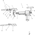
- the adjustment device for a headrest shown in Fig. 1 has a first headrest holder 1 for holding the headrest and a stationary first mounting plate 2 on which the first headrest holder 1 is held such that it can pivot about a first axis of rotation 3. Furthermore, a drive unit 4 is provided which has a linearly adjustable drive element 5. A guide 6 for the linearly adjustable drive element 5 is fastened to the first mounting plate 2 by means of screws 7. The end 8 of the drive unit 4 which is remote from the linearly adjustable drive element 5 is fixed on a holder 9, in which it is pushed onto a pin 10 and locked with a locking ring 11. The holder 9 is also arranged in a stationary manner and could, for example, also be formed by extending the first mounting plate 2.
- connection between the linearly adjustable drive element 5 and the first headrest holder 1 is formed by a coupling element 12 which has a pin 13 at one end, with which it is articulated to the drive element 5 and fixed by means of a locking ring 14.
- the other end of the coupling element 12 is articulated to the first headrest holder 1 at an articulation point 15.
- the first mounting plate 2 and the holder 9 are fastened to a component 16, which is, for example, the backrest of a piece of seating or reclining furniture.
- the drive unit 1 held on the holder 9 and on the guide 6 is thus arranged in a stationary manner with respect to the component 16, so that the adjustment of the linearly adjustable drive element 5 of the drive unit 1 takes place along a stationary spatial axis 17 between an initial position ( Fig. 2 ) and an end position ( Fig. 4 ).
- a headrest 18 is fastened to the first headrest holder 1 and is adjustable from a rearwardly folded position according to Fig. 2 via an intermediate position ( Fig. 3 ) to a forwardly inclined position according to Fig. 4 , whereby of course every other intermediate position can also be assumed.
- the first headrest holder 1 rotates with the headrest 18 around the articulation point 15 and in this way changes the inclination of the headrest 18.
- the headrest 18 is folded back in Fig. 2 and aligned approximately horizontally.
- the coupling element is freely movable in the region of the pin 13 and the articulation point 15.
- the headrest 18 is pivoted upwards through an angle ⁇ of approximately 90° and is thus oriented approximately vertically.
- the pin 13 and the articulation point 15 lie on the stationary spatial axis 17, in the direction of which the drive element 5 is adjustable.
- the coupling element comes into contact with a stop element 19 arranged on the first headrest holder 1, the stop element 19 being arranged in such a way that it blocks a rotation of the coupling element 12 relative to the first headrest holder 1 upon further adjustment of the headrest 18 into the end position shown in Fig. 4 .
- the headrest 18 or the first headrest holder 1 can be tilted forward by a further angle ⁇ of approximately 50°, so that a total pivoting angle ( ⁇ + ⁇ ) of approximately 140° results.
- the adjustment device furthermore has a second headrest holder 20 which is pivotable on a second mounting plate 21 about a second axis of rotation 22, the first headrest holder and the second headrest holder also being arranged at a distance from one another, in particular on the backrest of the seating or reclining furniture, in such a way that the first axis of rotation 3 and the second axis of rotation 22 are aligned.
- the first headrest holder 1 and the second headrest holder 20 these are connected to one another via the headrest 18 (not shown).
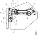
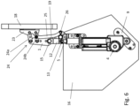
- Fig. 5 to 7 show a second embodiment of the adjustment device according to the invention for a headrest, which differs from the first embodiment only in that a first extension element 23 is articulated to the first headrest holder 1 at an end remote from the first axis of rotation 3, the first extension element 23 between a retracted position ( Fig. 5 ) and an extended position ( Fig. 7 ) being pivotable relative to the first headrest holder 1.
- the first extension element 23 is held on the first headrest holder 1 via a first pivot mechanism 24, the first pivot mechanism 24 being designed in the illustrated embodiment with two lever arms 24a, 24b in the manner of a parallelogram guide.
- the two lever arms 24a, 24b which are aligned parallel to one another, are articulated at one end to the first headrest holder and articulated to the extension element 23 at the other end.
- a first coupling arm 25 is provided, one end of which is articulated to the first pivot mechanism 24, in this case to the lever arm 24b thereof, and the other end to an articulation point 26 provided on the first mounting plate 2.
- Fig. 5 again shows the position of the headrest 18 folded backwards
- Fig. 6 shows the intermediate position
- Fig. 7 shows the forwardly inclined end position of the headrest 18.
- the rotational movement of the first headrest holder 1 via the coupling element 12 and the linearly adjustable drive element 5 corresponds to that of the first embodiment.
- the coupling of the first pivot mechanism 24 to the first coupling arm 25 causes the first extension element 23 to pivot relative to the first headrest holder 1 in the sense of an extension of the first headrest holder 1 by the amount a ( Fig. 7 ).
- the headrest 18 reaches a somewhat greater distance from the seat surface in the forwardly inclined position, while it is arranged relatively compactly in the folded-back position and does not protrude excessively backwards beyond the backrest (component 16).
- a second extension element (not shown) is articulated to the second headrest holder 20 ( Fig. 1 ) at an end remote from the second axis of rotation 22, the first extension element 23 and the second extension element being connected to one another, in particular via the headrest 18 for synchronous adjustment.
Landscapes
- Chair Legs, Seat Parts, And Backrests (AREA)
Applications Claiming Priority (1)
| Application Number | Priority Date | Filing Date | Title |
|---|---|---|---|
| DE202021100215.8U DE202021100215U1 (de) | 2021-01-18 | 2021-01-18 | Verstellvorrichtung für eine Kopfstütze |
Publications (2)
| Publication Number | Publication Date |
|---|---|
| EP4029409A1 EP4029409A1 (en) | 2022-07-20 |
| EP4029409B1 true EP4029409B1 (en) | 2023-11-01 |
Family
ID=74686425
Family Applications (1)
| Application Number | Title | Priority Date | Filing Date |
|---|---|---|---|
| EP21206340.8A Active EP4029409B1 (en) | 2021-01-18 | 2021-11-04 | Adjustment device for a headrest |
Country Status (5)
| Country | Link |
|---|---|
| EP (1) | EP4029409B1 (pl) |
| CN (1) | CN216932458U (pl) |
| DE (1) | DE202021100215U1 (pl) |
| ES (1) | ES2963167T3 (pl) |
| PL (1) | PL4029409T3 (pl) |
Families Citing this family (1)
| Publication number | Priority date | Publication date | Assignee | Title |
|---|---|---|---|---|
| DE202023103692U1 (de) * | 2023-07-04 | 2023-07-18 | Ciar S.P.A. | Verstellvorrichtung für eine Kopfstütze |
Family Cites Families (6)
| Publication number | Priority date | Publication date | Assignee | Title |
|---|---|---|---|---|
| DE2932344A1 (de) | 1979-08-09 | 1981-02-26 | Ritter Ag | Vorrichtung zur verstellung einer kopfstuetze |
| US5640730A (en) * | 1995-05-11 | 1997-06-24 | Maxwell Products, Inc. | Adjustable articulated bed with tiltable head portion |
| DE102014100303A1 (de) * | 2014-01-13 | 2015-07-16 | Ferdinand Lusch Gmbh & Co. Kg | Sitzmöbel mit motorisch verschwenkbarem Kopfteil |
| US9282827B1 (en) * | 2015-01-30 | 2016-03-15 | Dongguan Weihong Hardware And Plastic Products Co., Ltd. | Lifting stand for adjusting headrest |
| DE102015119326A1 (de) * | 2015-11-10 | 2017-05-11 | Ferdinand Lusch Gmbh & Co. Kg | Sitzmöbel mit einem separaten und schwenkbaren Kopfteil |
| CN105534136B (zh) | 2016-01-25 | 2018-09-11 | 东莞市伟宏五金塑胶制品有限公司 | 自动升降头枕架 |
-
2021
- 2021-01-18 DE DE202021100215.8U patent/DE202021100215U1/de active Active
- 2021-11-04 PL PL21206340.8T patent/PL4029409T3/pl unknown
- 2021-11-04 EP EP21206340.8A patent/EP4029409B1/en active Active
- 2021-11-04 ES ES21206340T patent/ES2963167T3/es active Active
- 2021-12-09 CN CN202123085999.9U patent/CN216932458U/zh active Active
Also Published As
| Publication number | Publication date |
|---|---|
| CN216932458U (zh) | 2022-07-12 |
| DE202021100215U1 (de) | 2021-02-04 |
| ES2963167T3 (es) | 2024-03-25 |
| EP4029409A1 (en) | 2022-07-20 |
| PL4029409T3 (pl) | 2024-02-05 |
Similar Documents
| Publication | Publication Date | Title |
|---|---|---|
| US10897995B2 (en) | Pivot-over-arm reclining mechanism for a seating unit and modular seating unit connection system | |
| US5071189A (en) | Chair with adjustment feature | |
| CA3138503C (en) | Zero-wall clearance linkage mechanism with power seat drive | |
| EP3171734B1 (en) | Zero-wall clearance linkage mechanism with power seat drive | |
| CN105455480B (zh) | 头枕倾斜机构 | |
| US9962004B2 (en) | Profile ottoman linkage | |
| US8172315B2 (en) | Device for a reclining chair | |
| US8851563B2 (en) | Furniture fitting system | |
| WO2001060211B1 (en) | Adjustable chair | |
| WO2008112130A2 (en) | Zero clearance recliner mechanism | |
| US6692075B2 (en) | Chair having a synchronously adjustable seat and backrest | |
| US20080012414A1 (en) | Armchair | |
| CN110710816A (zh) | 用于头枕的调节装置 | |
| US20050140183A1 (en) | Reclining chair with foot and leg rest | |
| EP4029409B1 (en) | Adjustment device for a headrest | |
| EP3949808B1 (en) | Seating and reclining furniture | |
| US6672668B1 (en) | Examination chair | |
| US5464269A (en) | Upholstered furniture and movable headrest | |
| EP4487733B1 (en) | Adjustment device for a headrest | |
| DK146373B (da) | Indstillingsmekanisme til haevning og saenkning af en laenestol til at sidde og/eller ligge i | |
| WO1995025452A1 (en) | A chair with a reclinable backrest | |
| US7152927B1 (en) | Ratcheted headrest for a recliner chair | |
| CN114532782B (zh) | 具有站立辅助装置的座椅家具 | |
| NO20221354A1 (en) | Recliner chair | |
| CN118042961A (zh) | 具有单电机离墙功能和共同运行的靠背传动装置的座椅 |
Legal Events
| Date | Code | Title | Description |
|---|---|---|---|
| PUAI | Public reference made under article 153(3) epc to a published international application that has entered the european phase |
Free format text: ORIGINAL CODE: 0009012 |
|
| STAA | Information on the status of an ep patent application or granted ep patent |
Free format text: STATUS: REQUEST FOR EXAMINATION WAS MADE |
|
| 17P | Request for examination filed |
Effective date: 20220429 |
|
| AK | Designated contracting states |
Kind code of ref document: A1 Designated state(s): AL AT BE BG CH CY CZ DE DK EE ES FI FR GB GR HR HU IE IS IT LI LT LU LV MC MK MT NL NO PL PT RO RS SE SI SK SM TR |
|
| GRAP | Despatch of communication of intention to grant a patent |
Free format text: ORIGINAL CODE: EPIDOSNIGR1 |
|
| STAA | Information on the status of an ep patent application or granted ep patent |
Free format text: STATUS: GRANT OF PATENT IS INTENDED |
|
| INTG | Intention to grant announced |
Effective date: 20230823 |
|
| GRAS | Grant fee paid |
Free format text: ORIGINAL CODE: EPIDOSNIGR3 |
|
| GRAA | (expected) grant |
Free format text: ORIGINAL CODE: 0009210 |
|
| STAA | Information on the status of an ep patent application or granted ep patent |
Free format text: STATUS: THE PATENT HAS BEEN GRANTED |
|
| AK | Designated contracting states |
Kind code of ref document: B1 Designated state(s): AL AT BE BG CH CY CZ DE DK EE ES FI FR GB GR HR HU IE IS IT LI LT LU LV MC MK MT NL NO PL PT RO RS SE SI SK SM TR |
|
| REG | Reference to a national code |
Ref country code: GB Ref legal event code: FG4D |
|
| REG | Reference to a national code |
Ref country code: CH Ref legal event code: EP |
|
| REG | Reference to a national code |
Ref country code: IE Ref legal event code: FG4D |
|
| REG | Reference to a national code |
Ref country code: DE Ref legal event code: R096 Ref document number: 602021006399 Country of ref document: DE |
|
| REG | Reference to a national code |
Ref country code: LT Ref legal event code: MG9D |
|
| REG | Reference to a national code |
Ref country code: NL Ref legal event code: MP Effective date: 20231101 |
|
| REG | Reference to a national code |
Ref country code: ES Ref legal event code: FG2A Ref document number: 2963167 Country of ref document: ES Kind code of ref document: T3 Effective date: 20240325 |
|
| PG25 | Lapsed in a contracting state [announced via postgrant information from national office to epo] |
Ref country code: GR Free format text: LAPSE BECAUSE OF FAILURE TO SUBMIT A TRANSLATION OF THE DESCRIPTION OR TO PAY THE FEE WITHIN THE PRESCRIBED TIME-LIMIT Effective date: 20240202 |
|
| PG25 | Lapsed in a contracting state [announced via postgrant information from national office to epo] |
Ref country code: IS Free format text: LAPSE BECAUSE OF FAILURE TO SUBMIT A TRANSLATION OF THE DESCRIPTION OR TO PAY THE FEE WITHIN THE PRESCRIBED TIME-LIMIT Effective date: 20240301 |
|
| PG25 | Lapsed in a contracting state [announced via postgrant information from national office to epo] |
Ref country code: LT Free format text: LAPSE BECAUSE OF FAILURE TO SUBMIT A TRANSLATION OF THE DESCRIPTION OR TO PAY THE FEE WITHIN THE PRESCRIBED TIME-LIMIT Effective date: 20231101 |
|
| REG | Reference to a national code |
Ref country code: AT Ref legal event code: MK05 Ref document number: 1626199 Country of ref document: AT Kind code of ref document: T Effective date: 20231101 |
|
| PG25 | Lapsed in a contracting state [announced via postgrant information from national office to epo] |
Ref country code: NL Free format text: LAPSE BECAUSE OF FAILURE TO SUBMIT A TRANSLATION OF THE DESCRIPTION OR TO PAY THE FEE WITHIN THE PRESCRIBED TIME-LIMIT Effective date: 20231101 |
|
| PG25 | Lapsed in a contracting state [announced via postgrant information from national office to epo] |
Ref country code: AT Free format text: LAPSE BECAUSE OF FAILURE TO SUBMIT A TRANSLATION OF THE DESCRIPTION OR TO PAY THE FEE WITHIN THE PRESCRIBED TIME-LIMIT Effective date: 20231101 |
|
| PG25 | Lapsed in a contracting state [announced via postgrant information from national office to epo] |
Ref country code: NL Free format text: LAPSE BECAUSE OF FAILURE TO SUBMIT A TRANSLATION OF THE DESCRIPTION OR TO PAY THE FEE WITHIN THE PRESCRIBED TIME-LIMIT Effective date: 20231101 Ref country code: LT Free format text: LAPSE BECAUSE OF FAILURE TO SUBMIT A TRANSLATION OF THE DESCRIPTION OR TO PAY THE FEE WITHIN THE PRESCRIBED TIME-LIMIT Effective date: 20231101 Ref country code: IS Free format text: LAPSE BECAUSE OF FAILURE TO SUBMIT A TRANSLATION OF THE DESCRIPTION OR TO PAY THE FEE WITHIN THE PRESCRIBED TIME-LIMIT Effective date: 20240301 Ref country code: GR Free format text: LAPSE BECAUSE OF FAILURE TO SUBMIT A TRANSLATION OF THE DESCRIPTION OR TO PAY THE FEE WITHIN THE PRESCRIBED TIME-LIMIT Effective date: 20240202 Ref country code: BG Free format text: LAPSE BECAUSE OF FAILURE TO SUBMIT A TRANSLATION OF THE DESCRIPTION OR TO PAY THE FEE WITHIN THE PRESCRIBED TIME-LIMIT Effective date: 20240201 Ref country code: AT Free format text: LAPSE BECAUSE OF FAILURE TO SUBMIT A TRANSLATION OF THE DESCRIPTION OR TO PAY THE FEE WITHIN THE PRESCRIBED TIME-LIMIT Effective date: 20231101 Ref country code: PT Free format text: LAPSE BECAUSE OF FAILURE TO SUBMIT A TRANSLATION OF THE DESCRIPTION OR TO PAY THE FEE WITHIN THE PRESCRIBED TIME-LIMIT Effective date: 20240301 |
|
| PG25 | Lapsed in a contracting state [announced via postgrant information from national office to epo] |
Ref country code: SE Free format text: LAPSE BECAUSE OF FAILURE TO SUBMIT A TRANSLATION OF THE DESCRIPTION OR TO PAY THE FEE WITHIN THE PRESCRIBED TIME-LIMIT Effective date: 20231101 Ref country code: RS Free format text: LAPSE BECAUSE OF FAILURE TO SUBMIT A TRANSLATION OF THE DESCRIPTION OR TO PAY THE FEE WITHIN THE PRESCRIBED TIME-LIMIT Effective date: 20231101 Ref country code: NO Free format text: LAPSE BECAUSE OF FAILURE TO SUBMIT A TRANSLATION OF THE DESCRIPTION OR TO PAY THE FEE WITHIN THE PRESCRIBED TIME-LIMIT Effective date: 20240201 Ref country code: LV Free format text: LAPSE BECAUSE OF FAILURE TO SUBMIT A TRANSLATION OF THE DESCRIPTION OR TO PAY THE FEE WITHIN THE PRESCRIBED TIME-LIMIT Effective date: 20231101 Ref country code: HR Free format text: LAPSE BECAUSE OF FAILURE TO SUBMIT A TRANSLATION OF THE DESCRIPTION OR TO PAY THE FEE WITHIN THE PRESCRIBED TIME-LIMIT Effective date: 20231101 |
|
| PG25 | Lapsed in a contracting state [announced via postgrant information from national office to epo] |
Ref country code: DK Free format text: LAPSE BECAUSE OF FAILURE TO SUBMIT A TRANSLATION OF THE DESCRIPTION OR TO PAY THE FEE WITHIN THE PRESCRIBED TIME-LIMIT Effective date: 20231101 |
|
| PG25 | Lapsed in a contracting state [announced via postgrant information from national office to epo] |
Ref country code: LU Free format text: LAPSE BECAUSE OF NON-PAYMENT OF DUE FEES Effective date: 20231104 |
|
| PG25 | Lapsed in a contracting state [announced via postgrant information from national office to epo] |
Ref country code: CZ Free format text: LAPSE BECAUSE OF FAILURE TO SUBMIT A TRANSLATION OF THE DESCRIPTION OR TO PAY THE FEE WITHIN THE PRESCRIBED TIME-LIMIT Effective date: 20231101 |
|
| PG25 | Lapsed in a contracting state [announced via postgrant information from national office to epo] |
Ref country code: SK Free format text: LAPSE BECAUSE OF FAILURE TO SUBMIT A TRANSLATION OF THE DESCRIPTION OR TO PAY THE FEE WITHIN THE PRESCRIBED TIME-LIMIT Effective date: 20231101 |
|
| PG25 | Lapsed in a contracting state [announced via postgrant information from national office to epo] |
Ref country code: SM Free format text: LAPSE BECAUSE OF FAILURE TO SUBMIT A TRANSLATION OF THE DESCRIPTION OR TO PAY THE FEE WITHIN THE PRESCRIBED TIME-LIMIT Effective date: 20231101 Ref country code: SK Free format text: LAPSE BECAUSE OF FAILURE TO SUBMIT A TRANSLATION OF THE DESCRIPTION OR TO PAY THE FEE WITHIN THE PRESCRIBED TIME-LIMIT Effective date: 20231101 Ref country code: EE Free format text: LAPSE BECAUSE OF FAILURE TO SUBMIT A TRANSLATION OF THE DESCRIPTION OR TO PAY THE FEE WITHIN THE PRESCRIBED TIME-LIMIT Effective date: 20231101 Ref country code: DK Free format text: LAPSE BECAUSE OF FAILURE TO SUBMIT A TRANSLATION OF THE DESCRIPTION OR TO PAY THE FEE WITHIN THE PRESCRIBED TIME-LIMIT Effective date: 20231101 Ref country code: CZ Free format text: LAPSE BECAUSE OF FAILURE TO SUBMIT A TRANSLATION OF THE DESCRIPTION OR TO PAY THE FEE WITHIN THE PRESCRIBED TIME-LIMIT Effective date: 20231101 Ref country code: LU Free format text: LAPSE BECAUSE OF NON-PAYMENT OF DUE FEES Effective date: 20231104 |
|
| REG | Reference to a national code |
Ref country code: BE Ref legal event code: MM Effective date: 20231130 |
|
| REG | Reference to a national code |
Ref country code: DE Ref legal event code: R097 Ref document number: 602021006399 Country of ref document: DE |
|
| PG25 | Lapsed in a contracting state [announced via postgrant information from national office to epo] |
Ref country code: MC Free format text: LAPSE BECAUSE OF FAILURE TO SUBMIT A TRANSLATION OF THE DESCRIPTION OR TO PAY THE FEE WITHIN THE PRESCRIBED TIME-LIMIT Effective date: 20231101 |
|
| PG25 | Lapsed in a contracting state [announced via postgrant information from national office to epo] |
Ref country code: MC Free format text: LAPSE BECAUSE OF FAILURE TO SUBMIT A TRANSLATION OF THE DESCRIPTION OR TO PAY THE FEE WITHIN THE PRESCRIBED TIME-LIMIT Effective date: 20231101 |
|
| PLBE | No opposition filed within time limit |
Free format text: ORIGINAL CODE: 0009261 |
|
| STAA | Information on the status of an ep patent application or granted ep patent |
Free format text: STATUS: NO OPPOSITION FILED WITHIN TIME LIMIT |
|
| REG | Reference to a national code |
Ref country code: IE Ref legal event code: MM4A |
|
| 26N | No opposition filed |
Effective date: 20240802 |
|
| PG25 | Lapsed in a contracting state [announced via postgrant information from national office to epo] |
Ref country code: IE Free format text: LAPSE BECAUSE OF NON-PAYMENT OF DUE FEES Effective date: 20231104 |
|
| PG25 | Lapsed in a contracting state [announced via postgrant information from national office to epo] |
Ref country code: BE Free format text: LAPSE BECAUSE OF NON-PAYMENT OF DUE FEES Effective date: 20231130 |
|
| PG25 | Lapsed in a contracting state [announced via postgrant information from national office to epo] |
Ref country code: SI Free format text: LAPSE BECAUSE OF FAILURE TO SUBMIT A TRANSLATION OF THE DESCRIPTION OR TO PAY THE FEE WITHIN THE PRESCRIBED TIME-LIMIT Effective date: 20231101 |
|
| PG25 | Lapsed in a contracting state [announced via postgrant information from national office to epo] |
Ref country code: SI Free format text: LAPSE BECAUSE OF FAILURE TO SUBMIT A TRANSLATION OF THE DESCRIPTION OR TO PAY THE FEE WITHIN THE PRESCRIBED TIME-LIMIT Effective date: 20231101 Ref country code: IE Free format text: LAPSE BECAUSE OF NON-PAYMENT OF DUE FEES Effective date: 20231104 Ref country code: BE Free format text: LAPSE BECAUSE OF NON-PAYMENT OF DUE FEES Effective date: 20231130 |
|
| PG25 | Lapsed in a contracting state [announced via postgrant information from national office to epo] |
Ref country code: RO Free format text: LAPSE BECAUSE OF FAILURE TO SUBMIT A TRANSLATION OF THE DESCRIPTION OR TO PAY THE FEE WITHIN THE PRESCRIBED TIME-LIMIT Effective date: 20231101 |
|
| REG | Reference to a national code |
Ref country code: CH Ref legal event code: PL |
|
| PG25 | Lapsed in a contracting state [announced via postgrant information from national office to epo] |
Ref country code: FI Free format text: LAPSE BECAUSE OF FAILURE TO SUBMIT A TRANSLATION OF THE DESCRIPTION OR TO PAY THE FEE WITHIN THE PRESCRIBED TIME-LIMIT Effective date: 20231101 |
|
| REG | Reference to a national code |
Ref country code: CH Ref legal event code: PL |
|
| PG25 | Lapsed in a contracting state [announced via postgrant information from national office to epo] |
Ref country code: CH Free format text: LAPSE BECAUSE OF NON-PAYMENT OF DUE FEES Effective date: 20241130 |
|
| PG25 | Lapsed in a contracting state [announced via postgrant information from national office to epo] |
Ref country code: CY Free format text: LAPSE BECAUSE OF FAILURE TO SUBMIT A TRANSLATION OF THE DESCRIPTION OR TO PAY THE FEE WITHIN THE PRESCRIBED TIME-LIMIT; INVALID AB INITIO Effective date: 20211104 |
|
| PG25 | Lapsed in a contracting state [announced via postgrant information from national office to epo] |
Ref country code: TR Free format text: LAPSE BECAUSE OF FAILURE TO SUBMIT A TRANSLATION OF THE DESCRIPTION OR TO PAY THE FEE WITHIN THE PRESCRIBED TIME-LIMIT Effective date: 20231101 |
|
| PGFP | Annual fee paid to national office [announced via postgrant information from national office to epo] |
Ref country code: DE Payment date: 20251103 Year of fee payment: 5 |
|
| PGFP | Annual fee paid to national office [announced via postgrant information from national office to epo] |
Ref country code: IT Payment date: 20251119 Year of fee payment: 5 |
|
| PGFP | Annual fee paid to national office [announced via postgrant information from national office to epo] |
Ref country code: FR Payment date: 20251126 Year of fee payment: 5 |
|
| PGFP | Annual fee paid to national office [announced via postgrant information from national office to epo] |
Ref country code: PL Payment date: 20251022 Year of fee payment: 5 |
|
| PGFP | Annual fee paid to national office [announced via postgrant information from national office to epo] |
Ref country code: ES Payment date: 20251229 Year of fee payment: 5 |
|
| PG25 | Lapsed in a contracting state [announced via postgrant information from national office to epo] |
Ref country code: HU Free format text: LAPSE BECAUSE OF FAILURE TO SUBMIT A TRANSLATION OF THE DESCRIPTION OR TO PAY THE FEE WITHIN THE PRESCRIBED TIME-LIMIT; INVALID AB INITIO Effective date: 20211104 |