EP4029400A1 - Ear piercing gun - Google Patents
Ear piercing gun Download PDFInfo
- Publication number
- EP4029400A1 EP4029400A1 EP20926330.0A EP20926330A EP4029400A1 EP 4029400 A1 EP4029400 A1 EP 4029400A1 EP 20926330 A EP20926330 A EP 20926330A EP 4029400 A1 EP4029400 A1 EP 4029400A1
- Authority
- EP
- European Patent Office
- Prior art keywords
- disposed
- gun
- stud
- rear portion
- ear piercing
- Prior art date
- Legal status (The legal status is an assumption and is not a legal conclusion. Google has not performed a legal analysis and makes no representation as to the accuracy of the status listed.)
- Pending
Links
- 238000010304 firing Methods 0.000 claims abstract description 130
- 210000000624 ear auricle Anatomy 0.000 claims abstract description 25
- 239000000837 restrainer Substances 0.000 claims abstract description 15
- 230000000903 blocking effect Effects 0.000 claims description 22
- 238000000034 method Methods 0.000 abstract description 14
- 230000008569 process Effects 0.000 abstract description 14
- 238000010586 diagram Methods 0.000 description 13
- 210000003811 finger Anatomy 0.000 description 7
- 230000009471 action Effects 0.000 description 6
- 210000003813 thumb Anatomy 0.000 description 6
- 210000003128 head Anatomy 0.000 description 5
- 230000001960 triggered effect Effects 0.000 description 4
- 238000003754 machining Methods 0.000 description 3
- 230000007246 mechanism Effects 0.000 description 3
- 210000005069 ears Anatomy 0.000 description 2
- 238000004519 manufacturing process Methods 0.000 description 2
- 230000005489 elastic deformation Effects 0.000 description 1
- 239000000463 material Substances 0.000 description 1
- 238000012986 modification Methods 0.000 description 1
- 230000004048 modification Effects 0.000 description 1
- 238000004806 packaging method and process Methods 0.000 description 1
- 238000006467 substitution reaction Methods 0.000 description 1
Images


Classifications
-
- A—HUMAN NECESSITIES
- A44—HABERDASHERY; JEWELLERY
- A44C—PERSONAL ADORNMENTS, e.g. JEWELLERY; COINS
- A44C7/00—Ear-rings; Devices for piercing the ear-lobes
- A44C7/001—Devices for piercing the ear-lobes
Definitions
- the present application relates to the technical field of auxiliary ornament mounting devices, in particular to a gun-shaped ear piercing instrument.
- Spring-driven gun-shaped ear piercing instruments with similar components such as a piercer body, a stud mounting portion and a stud base mounting portion, have been around for a long time.
- the stud mounting portion and the stud base mounting portion are firstly brought closer to the earlobe, and then a trigger releases a pre-compressed spring, so that the spring drives the stud mounting portion to move forward, and a tip of a stud is pierced into a stud base after piercing through the earlobe.
- the stud mounting portion and the stud base mounting portion are separated from each other and detached from the body of the gun-shaped ear piercing instrument at the same time, leaving the stud and the stud base on the earlobe. In this way, the entire ear piercing process is completed.
- two piercers In order to avoid the pain caused by piercing the ears twice respectively, two piercers generally needs to aim at the earlobes on both sides for positioning, and then triggers are pulled to release firing springs at the same time, so that the ear piercing operation on both sides can be carried out at the same time, ensuring that customers will get pain only once, reducing customer's discomfort and improving customer experience.
- the stud base mounting portion is driven to get close to the stud mounting portion by pulling the trigger (the stud mounting portion keeps still while the stud base mounting portion moves closer), and the firing spring is released by triggering when the stud base mounting portion further moves to a certain position.
- the trigger the stud mounting portion keeps still while the stud base mounting portion moves closer
- the firing spring is released by triggering when the stud base mounting portion further moves to a certain position.
- the stud base mounting portion is driven to get close to the stud mounting portion by pulling the trigger (the stud mounting portion keeps still while the stud base mounting portion moves closer), and then the firing spring is unlocked by the thumb.
- the requirement of keeping the first gun-shaped ear piercing instrument still after this piercer aims at the earlobe can be met to avoid false triggering.
- triggering by the thumb will cause a large hand motion, which easily makes the position of the first gun-shaped ear piercing instrument held by hand deviate from a piercing position, and thus results in an offset piercing position on the ear.
- the technical problem to be solved in the present application is to provide a gun-shaped ear piercing instrument, which can reduce the finger motion amplitude of operators in the process of ear piercing and improve the accuracy and efficiency of ear piercing.
- a gun-shaped ear piercing instrument comprising a front portion and a rear portion, which are sleeved together and can move relatively; a track, having a front slot for mounting a stud base mounting portion disposed on one end thereof away from the rear portion, as well as a fixing portion for mounting a stud mounting portion disposed thereon in a sliding manner, is disposed on the front portion; a firing device corresponding to the fixing portion is disposed on the rear portion; and the front portion comprises a grip having an unlocking trigger disposed on a front side thereof, an elastic reset device as well as an aiming stroke restrainer are disposed between the front portion and the rear portion, the aiming stroke restrainer is configured to restrain the firing device so as to help the firing device to move to an aiming position when firing device is in an aiming stroke, and the unlocking trigger is configured to trigger the firing device to enter an piercing stroke for piercing the earlobe.
- a spring locking piece which is disposed on a firing path of the firing device for locking the firing device, is disposed in the rear portion, and the unlocking trigger is in drive connection with spring locking piece to drive the spring locking piece to unlock the firing device.
- the spring locking piece is disposed on the rear portion, a torsion spring for returning the spring locking piece is disposed between the spring locking piece and the rear portion, and the spring locking piece comprises a locking end configured to lock the firing device and a triggering end configured to unlock together with the unlocking trigger.
- a hollow tube is disposed on the top of the rear portion, the firing device comprises a firing pin and a firing spring, which are mounted in the hollow tube, and both ends of the firing spring are elastically propped against the firing pin and the firing spring respectively; and a strip-shaped notch is disposed below the hollow tube, and the locking end of the spring locking piece extends into the notch to lock the firing device together with the firing pin.
- a ring groove is disposed on the firing pin, and the locking end of the spring locking piece is snapped into the ring groove when the spring locking piece is locked, and is detached from the ring groove when the spring locking piece is unlocked.
- the firing pin comprises a major-diameter section disposed at a front end thereof, as well as a minor-diameter section disposed at a rear end thereof and coming out from the hollow tube, the ring groove is disposed at the major-diameter section, one end of the firing spring is propped against one end of the major-diameter section connected to the minor-diameter section, while the other end thereof is propped against an end wall of the hollow tube.
- a mounting groove having the unlocking trigger disposed therein, is disposed on a front side of the grip of the front portion, a first end of the unlocking trigger is hinged to the front portion and connected to the front portion through a torsion spring, while a second end thereof is blocked on an inner wall of the front portion; a trigger boss is disposed on the top of the unlocking trigger, and a side catch is disposed on at least one side of the unlocking trigger; and a straight slot is disposed on a lower side of the rear portion, the trigger boss is at least partially disposed in the straight slot, and the side catch is blocked outside the straight slot.
- a blocking piece protruding towards the unlocking trigger is further disposed on the lower side of the rear portion, the spring locking piece is disposed at a rear side of the blocking piece; before the front portion and the rear portion are completely closed, the trigger boss of the unlocking trigger is located at the blocking piece, and the unlocking trigger is pressed against the inner wall of the front portion by the blocking piece; after the front portion and the rear portion are completely closed, the trigger boss of the unlocking trigger is staggered from the blocking piece and is fitted to the triggering end of the spring locking piece; the unlocking trigger can be pulled, and the trigger boss of the unlocking trigger can drive the triggering end of the spring locking piece to move, so that the locking end of the spring locking piece is moved away from a locked position to unlock the firing device.
- the rear portion is sleeved in the front portion
- the aiming stroke restrainer comprises stop pins disposed on the front portion, and stop grooves disposed on the rear portion; the stop pins are disposed on an upper portion and a lower portion of a fitting portion of the front portion and the rear portion respectively, and the stop grooves are disposed at corresponding positions of the rear portion, and the stroke of the stop pin in the stop groove is the aiming stroke.
- the fixing portion and the rear portion are disposed separately, the stop pin is disposed on the front portion, the stop groove in which the stop pin can slide is disposed on the rear portion, and a fixing portion return spring, with one end hooked to the stop pin and the other end connected to the fixing portion, is connected between the fixing portion and the front portion.
- the front portion is further provided with a stopper which is stopped between the fixing portion and an end of the hollow tube, so that a clearance is formed between the fixing portion and the hollow tube while the fixing portion return spring generates a pretensioning force before the front portion and the rear portion are closed.
- the gun-shaped ear piercing instrument further comprises the stud mounting portion having an elastic track, a stud holder and a stud, the elastic track is tubular and comprises a radial slit extending in the movement direction of the stud.
- the fixing portion is disposed at the end of the hollow tube and forms an integrated structure with the hollow tube.
- the gun-shaped ear piercing instrument further comprises the stud mounting portion having two elastic tracks, a stud which can slide in the elastic track is disposed in each track, and the stud mounting portion is of a centrosymmetric structure.
- the elastic track is of a tubular structure having a cylindrical inner cavity as well as at least two straight slots axially extending, and at least one straight slot runs through a tube wall of the tubular structure.
- the two straight slots of the tubular structure are located at both ends of the same diameter of the tubular structure respectively, and run through tube wall of the tubular structure.
- the two straight slots of the tubular structure are located at both ends of the same diameter of the tubular structure respectively, where one straight slot runs through the tube wall of the tubular structure, and the other straight slot, having a slot depth less than a wall thickness of the tubular structure, is located on an outer wall or an inner wall of the tubular structure.
- the gun-shaped ear piercing instrument comprises a front portion and a rear portion, which are sleeved together and can move relatively; a track, having a front slot for mounting a stud base mounting portion disposed on one end thereof away from the rear portion, as well as a fixing portion for mounting a stud mounting portion disposed thereon in a sliding manner, is disposed on the front portion; a firing device corresponding to the fixing portion is disposed on the rear portion; and the front portion comprises a grip having an unlocking trigger disposed on a front side thereof, an elastic reset device as well as an aiming stroke restrainer are disposed between the front portion and the rear portion, the aiming stroke restrainer is configured to restrain the firing device so as to help the firing device to move to an aiming position when firing device is in an aiming stroke, and the unlocking trigger is configured to trigger the firing device to enter an piercing stroke for piercing the earlobe.
- the front portion and the rear portion of the gun-shaped ear piercing instrument are reset by the elastic reset device, and the aiming stroke is confined by the aiming stroke restrainer, so that the gun-shaped ear piercing instrument can stably be stopped at the aiming position after entering the aiming stroke to meet the requirement of keeping a first ear piercing instrument that aims at the earlobe still, and the firing device is triggered by the separate unlocking trigger to enter the piercing stroke to make a stud pierce through the earlobe. Since the unlocking trigger is located at a front side of the grip of the front portion, the unlocking trigger when pulled may be held and triggered by fingers except the thumb.
- Slight hand motion may effectively avoid the problem that the first ear piercing instrument deviates from a piercing position in the process of triggering with the thumb, and ensure that two gun-shaped ear piercing instruments operate at the same time to make the piercing positions more accurate and hardly deviate from the piercing position, thus improving the convenience and accuracy of ear piercing operations.
- a gun-shaped ear piercing instrument including a front portion 1 and a rear portion 2, which are sleeved together and can move relatively.
- a firing device corresponding to the fixing portion 11 is disposed on the rear portion 2.
- the front portion 1 includes a grip having an unlocking trigger 6 disposed on a front side thereof, an elastic reset device as well as an aiming stroke restrainer are disposed between the front portion 1 and the rear portion 2, the aiming stroke restrainer is configured to restrain the firing device so as to help the firing device to move to an aiming position when firing device is in an aiming stroke, and the unlocking trigger 6 is configured to trigger the firing device to enter an piercing stroke for piercing the earlobe.
- the front portion 1 and the rear portion 2 of the gun-shaped ear piercing instrument are reset by the elastic reset device, and the aiming stroke is confined by the aiming stroke restrainer, so that the gun-shaped ear piercing instrument can stably be stopped at the aiming position after entering the aiming stroke to meet the requirement of keeping a first ear piercing instrument that aims at the earlobe still, and the firing device is triggered by the separate unlocking trigger 6 to enter the piercing stroke to make a stud 10a pierce through the earlobe. Since the unlocking trigger 6 is located at a front side of the grip of the front portion 1, the unlocking trigger 6 when pulled may be held and triggered by other fingers except the thumb.
- Slight hand motion may effectively avoid the problem that the first ear piercing instrument deviates from a piercing position in the process of triggering with the thumb, and ensure that two gun-shaped ear piercing instruments operate at the same time to make the piercing position more accurate and hardly deviate from the piercing position, thus improving the convenience and accuracy of ear piercing operations.
- the gun-shaped ear piercing instrument according to the present application is of a gun-shaped structure, in which the stud base mounting portion 9 and the stud mounting portion 10 are mounted on a gun barrel of the front portion 1, thus piercing the ears easily.
- the grip according to the present application is formed on a gun handle, where the grip consists of two portions, namely a grip of the front portion 1 and a grip of the rear portion 2 which are sleeved together to form a complete grip. Since the unlocking trigger 6, with its position similar to that of a trigger of a gun, is disposed on the grip of the front portion 1, the unlocking trigger 6 when pulled may be operated directly by the index finger in the same way as the gun, so that the unlocking trigger may be pulled more smoothly and ergonomically. Moreover, the motion of the index finger is only to pull the trigger slightly, so the motion is relatively slight, which can keep the overall stability and balance of the gun-shaped ear piercing instrument and thus effectively ensure the accuracy and reliability of the ear piercing operation
- the elastic reset device is disposed between the front portion 1 and the rear portion 2 to ensure that the two portions may be kept away from a predetermined position without external force, so that the firing device on the rear portion 2 is kept away from a position where the stud 10a is located before the operation of the gun-shaped ear piercing instrument starts, which facilitates operations such as mounting the stud 10a, and can reserve the movable space required for a next aiming stroke at the same time.
- the elastic reset device includes a handle return spring 8 with one end connected to the front portion 1 and the other end connected to the rear portion 2, so that the front portion 1 and the rear portion 2 are connected together to form a complete gun-shaped structure.
- a spring sleeve in which the handle return spring 8 is sleeved and fixed, is disposed on the rear portion 2, and a spring link, to which the handle return spring 8 is connected, is disposed on the front portion 1.
- the front portion 1 and the rear portion 2 can be directly held to close when needed. After overcoming the elastic action of the handle spring 8, the front portion 1 and the rear portion 2 are closed, with an overlapped portion thereof enlarging and the overall width of a holding portion reducing.
- the handle return spring 8 has an elastic force to expand outward, so when the external force disappears, the handle return spring 8 can spring the front portion 1 and the rear portion 2 apart, making the two restore the initial state.
- the track 7 is fixedly disposed on the front portion 1.
- the track 7 may be designed and machined separately from and then fixedly connected to the front portion 1, or may be directly molded on the front portion 1.
- the front slot 7a is disposed at one end of the track 7, and the fixing portion 11 is disposed at the other end.
- the fixing portion 11 is disposed on the track 7 in a sliding manner, so as to adjust its relative position with the front slot 7a. Because of the relative movement thereof, the fixing portion 11 and the front slot 7a can be configured to respectively mount the stud base mounting portion 9 and the stud mounting portion 10 which are separated.
- the separated structure is less costly to design and manufacture, but requires higher machining accuracy to ensure that the stud base mounting portion 9 and the stud mounting portion 10 are in place at the same time.
- the above mounting structure of the front slot 7a and the fixing portion 11 also applies to the cassette in which the stud base mounting portion 9 and the stud mounting portion 10 are integrated.
- the unlocking trigger 6 is disposed on the front portion 1, the spring locking piece 5 is disposed on the rear portion 2, the spring locking piece 5 needs to keep the firing device locked all the time before the firing device reaches the aiming position, and the unlocking trigger 6 needs to drive the spring locking piece 5 to unlock the firing device locked by the spring locking piece 5 after the firing device reaches the aiming position to ensure that the firing device can fire the stud 10a, so the driving relation between the unlocking trigger 6 and the spring locking piece 5 may be set in such way that the unlocking trigger 6 cannot drive the spring locking piece 5 if the unlocking trigger 6 and the spring locking piece 5 do not reach a driving position before the firing device reaches the aiming position.
- the driving relation may also be set in such way that a drive structure may be formed between the unlocking trigger 6 and the spring locking piece 5 before the firing device reaches the aiming position, but the unlocking trigger 6 is limited by other structures and thus cannot drive the spring locking piece 5. Only when the firing device reaches the aiming position will the unlocking trigger 6 be released by limiting structures. Only in this case, the unlocking trigger 6 can drive the spring locking piece 5.
- Such structure can effectively avoid the unlocking trigger 6 from falsely triggering the spring locking piece 5, and improve the operation safety, reliability and accuracy of the gun-shaped ear piercing instrument.
- the spring locking piece 5 may be rotatably disposed on the rear portion 2, a torsion spring 5a for returning the spring locking piece 5 is disposed between the spring locking piece 5 and the rear portion 2, and the spring locking piece 5 includes a locking end 5c configured to lock the firing device and a triggering end 5b configured to unlock together with the unlocking trigger 6.
- the spring locking piece 5 is similar to a lever structure, with a center section thereof mounted on the rear portion 2 through the torsion spring 5a, and the torque of the torsion spring 5a provides a locking force for locking the firing device.
- One end of the spring locking piece 5 forms a stop end that may be clamped on the firing path of the firing device to lock the firing device, while the other end thereof may form a driving relation with the unlocking trigger 6 after the firing device reaches the aiming position, and the firing device is unlocked under the drive of the unlocking trigger 6.
- a hollow tube 2a is disposed on the top of the rear portion 2, the firing device includes a firing pin 3 and a firing spring 4, which are mounted in the hollow tube 2a, and both ends of the firing spring 4 are elastically propped against the firing pin 3 and the firing spring 4 respectively.
- a strip-shaped notch 2b, below which the spring locking piece 5 is disposed, is disposed below the hollow tube 2a, and the locking end 5c of the spring locking piece 5 extends into the notch 2b to lock the firing device together with the firing pin 3.
- a ring groove 3b is disposed on the firing pin 3, and the locking end 5c of the spring locking piece 5 is snapped into the ring groove 3b when the spring locking piece 5 is locked, and is detached from the ring groove 3b when the spring locking piece 5 is unlocked.
- the ring groove 3b may also be a recess, provided that the locking end 5c of the spring locking piece 5 can be snapped into the recess to stop the firing pin 3.
- the firing pin 3 includes a major-diameter section disposed at a front end thereof, as well as a minor-diameter section disposed at a rear end thereof and coming out from the hollow tube 2a, the ring groove 3b is disposed at the major-diameter section, one end of the firing spring 4 is propped against one end of the major-diameter section connected to the minor-diameter section, while the other end thereof is propped against an end wall of the hollow tube 2a.
- the firing pin 3 is of a structure in which the major-diameter section and the minor-diameter section are fitted to each other, which may form a stop step by different diameters of the major-diameter section and the minor-diameter section, so that one end of the firing spring 4 may be stopped on the stop step while the other end thereof may be stopped on the end wall of the hollow tube 2a.
- a hole, through which the minor-diameter section partially comes out of the hollow tube 2a, is formed on the end wall of the hollow tube 2a, so that the firing pin 3 may be operated easily by the minor-diameter section.
- the firing pin 3 After firing, the firing pin 3 can be returned to its original position by operating the minor-diameter section, and the spring locking piece 5 can be snapped into the ring groove 3b of the firing pin 3 again, thus locking the firing pin 3 for the next piercing operation.
- a tail hook 3a suitable for holding is disposed on a tail of the firing pin 3 coming out of the hollow tube 2a.
- an eye splice may also be mounted on the tail hook 3a, so that the tail hook 3a can be pulled back more easily.
- the spring locking piece 5 is snapped into the ring groove 3b on the firing pin 3 to tighten the firing spring 4, so that the firing pin 3 is in a state to be fired.
- the stud mounting portion 10 is inserted into the fixing portion slot 11a of the fixing portion 11, and the firing pin 3 is just aimed at the stud 10a in an elastic track 10d.
- a mounting groove, having the unlocking trigger 6 disposed therein, is disposed on a front side of the grip of the front portion 1, a first end of the unlocking trigger 6 is hinged to the front portion 1 and connected to the front portion 1 through a torsion spring 6a, while a second end thereof is blocked on an inner wall of the front portion 1.
- a trigger boss 6c is disposed on the top of the unlocking trigger 6, and a side catch 6b is disposed on at least one side of the unlocking trigger 6; and a straight slot 2h is disposed on a lower side of the rear portion 2, the trigger boss 6c is at least partially disposed in the straight slot 2h, and the side catch 6b is blocked outside the straight slot 2h.
- the mounting groove is located at the front side of the grip, and its position is similar to that of a trigger of a pistol, allowing a more pistol-like structure and easier manual operations.
- the first end of the unlocking trigger 6 is hinged to the front portion 1, while the second end thereof is in a cantilever position and pressed against the inner wall of the front portion 1 under the elastic action of the torsion spring 6a. Therefore, before being operated by hand, the unlocking trigger 6 will not trigger the spring locking piece 5 under the elastic action of the torsion spring 6a to release the spring locking piece 5.
- the first end of the unlocking trigger 6 is hinged, and is provided with an arc-shaped structure at an end, which can provide a larger space for the unlocking trigger 6 to rotate without interference with the front portion 1, and thus more effectively ensure that the unlocking trigger 6 has enough release ability and larger moving range to release the spring locking piece 5 effectively.
- a hook is disposed at an end of the second end of the unlocking trigger 6, and an overhead hook is further disposed at a position where a wall of the mounting groove of the front portion 1 is fitted to the second end of the unlocking trigger 6.
- the hook of the unlocking trigger 6 is hooked to the overhead hook under the action of the torsion spring 6a, thus effectively preventing the second end of the unlocking trigger 6 from falling out of the mounting groove, and improving the stability and reliability of the mounting structure of the unlocking trigger 6 in the front portion 1.
- the side catch 6b is disposed on the side of the trigger boss 6c.
- the side catch 6b are disposed on both sides of the trigger boss 6c respectively, which can ensure that the wall of the straight slot 2h uniformly blocks the trigger boss 6c.
- the trigger boss 6c is provided to ensure that the unlocking trigger 6 only partially enters the straight slot 2h, and a raised structure of the trigger boss 6c forms a driving relation with the spring locking piece 5 more easily, so as to trigger and release the spring locking piece 5.
- a blocking piece 2f protruding towards the unlocking trigger 6 is further disposed on the lower side of the rear portion 2, the spring locking piece 5 is disposed at a rear side of the blocking piece 2f.
- the trigger boss 6c of the unlocking trigger 6 is located at the blocking piece 2f, and the unlocking trigger 6 is pressed against the inner wall of the front portion 1 by the blocking piece 2f.
- the trigger boss 6c of the unlocking trigger 6 is staggered from the blocking piece 2f, the side catch 6b passes over the protruded blocking piece 2f and is fitted to the triggering end 5b of the spring locking piece 5.
- the unlocking trigger 6 can fully rotate to a proper position, and the trigger boss 6c of the unlocking trigger 6 can drive the triggering end 5b of the spring locking piece 5 to move and in turn drive the spring locking piece 5 to rotate, so that the locking end 5c of the spring locking piece 5 is moved away from a locked position to unlock the firing device and release the firing spring 4, so as to complete the firing process.
- the blocking piece 2f is shorter than the aiming stroke in length, so that the trigger boss 6c of the unlocking trigger 6 can completely stagger from the blocking piece 2f and reaches a position where the spring locking piece 5 is located after the aiming stroke is finished, so as to unlock the spring locking piece 5 in time and effectively.
- the rear portion 2 is sleeved in the front portion 1, and the aiming stroke restrainer includes stop pins disposed on the front portion 1, and stop grooves disposed on the rear portion 2.
- the stop pins are disposed on an upper portion and a lower portion of a fitting portion of the front portion 1 and the rear portion 2 respectively, and the stop grooves are disposed at corresponding positions of the rear portion 2, and the stroke of the stop pin in the stop groove is the aiming stroke.
- the front portion 1 includes a front piece 1a and a rear piece 1b, which are spliced to form the front portion 1.
- the stop pins 1d and 1e are disposed on the front portion 1, and the stop grooves 2d and 2e are disposed on the rear portion 2, where the stop pin 1d can slide in the stop groove 2d, the stop pin 1e can slide in the stop groove 2e, and the stop groove 2d is parallel to the stop groove 2e.
- the structure in which the two sets of stop pins and stop grooves are fitted to each other can effectively guide the movement of the rear portion 2 relative to the front portion 1, thus ensuring the accuracy of the movement direction of the rear portion 2 and the accuracy of the ear piercing operation.
- the stroke of the stop pin in the stop groove is the aiming stroke, which can effectively confine the length and end point of the aiming stroke, and ensure the accuracy of the aiming position, ensure that the firing device stops in time after reaching the aiming position, to meet the requirement of keeping a first ear piercing instrument that aims at the earlobe still.
- the fixing portion 11 and the rear portion 2 are disposed separately, the stop pin 1c is disposed on the front portion 1, the stop groove 2c in which the stop pin 1c can slide is disposed on the rear portion 2, and a fixing portion return spring 11b, with one end hooked to the stop pin 1c and the other end connected to the fixing portion 11, is connected between the fixing portion 11 and the front portion 1.
- the fixing portion return spring 11b can pull the fixing portion 11 back, allowing the fixing portion 11 to return to its original position.
- the front portion 1 is further provided with a stopper 1f which is stopped between the fixing portion 11 and an end of the hollow tube 2a, so that a clearance 12 is formed between the fixing portion 11 and an end face 2g of the hollow tube while the fixing portion return spring 11b generates a pretensioning force before the front portion 1 and the rear portion 2 are closed.
- the clearance 12 between the fixing portion 11 and the end face 2g of the hollow tube makes a blister box 13, which serves as a material for packaging the stud base mounting portion 9 and the stud mounting portion 10, go down into place, so that the stud base mounting portion 9 and the stud mounting portion 10 can be snapped into the front slot 7a and the fixing portion slot 11a simultaneously.
- the gun-shaped ear piercing instrument further includes the stud mounting portion 10 having a elastic track 10d, a stud holder 10b and a stud 10a, the tubular elastic track 10d is tubular and includes a radial slit 10f extending in the movement direction of the stud 10a.
- the slit 10f allows the elastic track 10d to have a certain elastic force to properly clamp the stud holder 10b mounted in the elastic track 10d, so that the stud holder may be stably fixed without moving back and forth, and may also move under the action of the firing pin 3 with little friction.
- the stud holder 10b includes two clamping pieces 10b1 and 10b2, which, when closed, can clamp a stud head 10g in the middle to only expose a stud tip 10c.
- the whole piercing process of the gun-shaped ear piercing instrument includes three strokes, namely a first stroke (idle stroke) where the front portion 1 and the rear portion 2 of the gun-shaped ear piercing instrument are closed to eliminate the clearance 12, a second stroke (aiming stroke) where the stud mounting portion 10 and the stud base mounting portion 9 are closed to each other, and a third stroke (piercing stroke) where the spring and the firing pin 3 drive the stud 10a to move forward.
- the unlocking trigger 6 rotates to trigger the spring locking piece 5 to move down to release the firing spring 4, so that the firing pin 3 drive the stud holder 10b in the elastic track 10d and the stud 10a wrapped therein to move in the elastic track 10d, and the stud 10a is inserted into a stud base 9a after piercing through the earlobe.
- This stroke is the third stroke (piercing stroke) driven by the spring and the firing pin 3.
- the stud 10a takes three strokes from approaching to piercing the earlobe.
- the stud base mounting portion 9 is designed as a mechanism in which the stud base 9a will be detached from the stud base mounting portion 9 when the stud 10a is inserted into the stud base 9a
- the stud base 10 is also designed as a mechanism in which the stud 10a will be detached from the stud holder 10b once the stud holder 10b is detached from the elastic track 10d (the stud holder 10b is formed by closing the two clamping pieces 10b1 and 10b2 together, and will be automatically separated once detached from the elastic track 10d), so when the stud 10a is inserted into the stud base 9a after piercing through the earlobe, the stud base 9a and the stud 10a will be detached from the stud base mounting portion 9 and the elastic track 10d at the same time and both left on the earlobe. In this way, the entire ear piercing process is completed.
- a fixing portion 11 is disposed at an end of a hollow tube 2a and forms an integrated structure with the hollow tube 2a.
- a stud base mounting portion 9 and a stud mounting portion 10 are taken out of a blister box 13 and put into the gun-shaped ear piercing instrument respectively, so there is no clearance 12 between the fixing portion 11 and a firing pin 3, and the fixing portion 11 is connected to an end face 2g of the hollow tube.
- the fixing portion 11 is fixed on the rear portion 2, a fixing portion return spring 11b is also omitted, which simplifies the structure of the gun-shaped ear piercing instrument, and reduces the structural complexity and the machining cost.
- the gun-shaped ear piercing instrument further includes a stud mounting portion 10 having two elastic tracks 10d, a stud 10a which can slide in the elastic track 10d is disposed in each track, and the stud mounting portion 10 is of a centrosymmetric structure.
- the fixing portion 11 is provided at a front end of the hollow tube 2a of the rear portion 2.
- Each elastic track 10d is of a tubular structure having at least one slit 10f running through, and the stud 10a is directly mounted in the elastic track 10d.
- Two stud bases 9a are mounted on the stud base mounting portion 9, and two elastic tracks 10d each having a stud 10a mounted respectively therein are mounted on the stud mounting portion 10.
- the stud base mounting portion 9 and the stud base mounting portion 10 may be mounted on the gun-shaped ear piercing instrument to complete a second ear piercing operation. In this way, the cost is further reduced.
- Each elastic track 10d is of a tubular structure having a cylindrical inner cavity as well as at least two straight slots axially extending, and at least one straight slot runs through a tube wall of the tubular structure.
- the stud head 10g of the stud 10a is cylindrical. With the cylindrical stud head 10g, the stud 10a can be directly mounted in the elastic track 10d without the stud holder 10b, and the stud tip 10c keeps moving forward stably when the stud 10a moves in the elastic track 10d, thus reducing the cost of the stud 10a.
- the two straight slots of the tubular structure are located at both ends of the same diameter of the tubular structure respectively, and run through tube wall of the tubular structure.
- the two straight slots of the tubular structure are located at both ends of the same diameter of the tubular structure respectively, where one straight slot runs through the tube wall of the tubular structure, and the other straight slot, having a slot depth less than a wall thickness of the tubular structure, is located on an outer wall or an inner wall of the tubular structure, thus forming a flute 10h at a position which is a hinge point of elastic deformation of an elastic tube.
- the stud head 10g varying in diameter in a certain range can be stably mounted in the elastic track 10d, and can move back and forth while keeping the stud tip 10c of the stud 10a from swinging, thereby reducing the machining accuracy of the stud 10a and the production cost and improving the yield.
- the lower portion of the gun-shaped structure is held by hand, and the handle return spring 8 is pressed by closing the hand, so that the rear portion 2 moves toward the front portion 1, and the fixing portion 11 and the firing pin 3 move forward for an aiming stroke accordingly, so that the stud tip 10c of the stud 10a on the stud mounting portion 10 is close to the earlobe and keeps still. This is the process of aiming, positioning and keeping still before ear piercing.
- the unlocking trigger 6 rotates to trigger the spring locking piece 5 to move downward to release the firing spring 4, so that the firing pin 3 drives the stud 10a in the elastic track 10d to move forward to insert into the stud base 9a after piercing through the earlobe.
- the side catches 6b preventing false triggering are disposed on side faces of the unlocking trigger 6, and the protruded blocking pieces 2f are disposed on the rear portion 2.
- the side catch 6b will be blocked by the protruded blocking piece 2f on the rear portion 2 to limit the rotation of the unlocking trigger 6, thereby avoiding false triggering of the spring locking piece 5. Only when the front portion 1 and the rear portion 2 are completely closed will the side catch 6b pass over the protruded blocking piece 2f. In this case, the unlocking trigger 6 can fully rotate to a proper position to drive the spring locking piece 5 to rotate and release the firing spring 4, so as to complete the firing process.
- the stud base mounting portion 9 is designed as a mechanism in which the stud base 9a will be detached from the stud base mounting portion 9 when the stud 10a is pierced into the stud 9a, so when the stud 10a is pierced into the stud base 9a after piercing through the earlobe, the stud base 9a and the stud 10a will be detached from the stud base mounting portion 9 and the stud mounting portion 10 at the same time and both left on earlobe. In this way, the entire ear piercing process is completed.
Abstract
Description
- The present application claims the priority from the
Chinese Patent Application No. 202010183292.2, filed to the CNIPA on March 16, 2020 - The present application relates to the technical field of auxiliary ornament mounting devices, in particular to a gun-shaped ear piercing instrument.
- Spring-driven gun-shaped ear piercing instruments, with similar components such as a piercer body, a stud mounting portion and a stud base mounting portion, have been around for a long time. In a process of ear piercing, the stud mounting portion and the stud base mounting portion are firstly brought closer to the earlobe, and then a trigger releases a pre-compressed spring, so that the spring drives the stud mounting portion to move forward, and a tip of a stud is pierced into a stud base after piercing through the earlobe. Then the stud mounting portion and the stud base mounting portion are separated from each other and detached from the body of the gun-shaped ear piercing instrument at the same time, leaving the stud and the stud base on the earlobe. In this way, the entire ear piercing process is completed.
- At present, in the process of ear piercing, in order to avoid the pain caused by piercing the ears twice respectively, two piercers generally needs to aim at the earlobes on both sides for positioning, and then triggers are pulled to release firing springs at the same time, so that the ear piercing operation on both sides can be carried out at the same time, ensuring that customers will get pain only once, reducing customer's discomfort and improving customer experience.
- In existing gun-shaped ear piercing instruments, the stud base mounting portion is driven to get close to the stud mounting portion by pulling the trigger (the stud mounting portion keeps still while the stud base mounting portion moves closer), and the firing spring is released by triggering when the stud base mounting portion further moves to a certain position. Such structure is not conducive to keeping the first gun-shaped ear piercing instrument still after this piercer aims at the earlobe, and false triggering occurs easily.
- In order to solve this problem, in the prior art, the stud base mounting portion is driven to get close to the stud mounting portion by pulling the trigger (the stud mounting portion keeps still while the stud base mounting portion moves closer), and then the firing spring is unlocked by the thumb. With this design, the requirement of keeping the first gun-shaped ear piercing instrument still after this piercer aims at the earlobe can be met to avoid false triggering. However, triggering by the thumb will cause a large hand motion, which easily makes the position of the first gun-shaped ear piercing instrument held by hand deviate from a piercing position, and thus results in an offset piercing position on the ear.
- Therefore, the technical problem to be solved in the present application is to provide a gun-shaped ear piercing instrument, which can reduce the finger motion amplitude of operators in the process of ear piercing and improve the accuracy and efficiency of ear piercing.
- In order to solve the above problems, a gun-shaped ear piercing instrument is provided according to the present application, comprising a front portion and a rear portion, which are sleeved together and can move relatively; a track, having a front slot for mounting a stud base mounting portion disposed on one end thereof away from the rear portion, as well as a fixing portion for mounting a stud mounting portion disposed thereon in a sliding manner, is disposed on the front portion; a firing device corresponding to the fixing portion is disposed on the rear portion; and the front portion comprises a grip having an unlocking trigger disposed on a front side thereof, an elastic reset device as well as an aiming stroke restrainer are disposed between the front portion and the rear portion, the aiming stroke restrainer is configured to restrain the firing device so as to help the firing device to move to an aiming position when firing device is in an aiming stroke, and the unlocking trigger is configured to trigger the firing device to enter an piercing stroke for piercing the earlobe.
- Optionally, a spring locking piece, which is disposed on a firing path of the firing device for locking the firing device, is disposed in the rear portion, and the unlocking trigger is in drive connection with spring locking piece to drive the spring locking piece to unlock the firing device.
- Optionally, the spring locking piece is disposed on the rear portion, a torsion spring for returning the spring locking piece is disposed between the spring locking piece and the rear portion, and the spring locking piece comprises a locking end configured to lock the firing device and a triggering end configured to unlock together with the unlocking trigger.
- Optionally, a hollow tube is disposed on the top of the rear portion, the firing device comprises a firing pin and a firing spring, which are mounted in the hollow tube, and both ends of the firing spring are elastically propped against the firing pin and the firing spring respectively; and a strip-shaped notch is disposed below the hollow tube, and the locking end of the spring locking piece extends into the notch to lock the firing device together with the firing pin.
- Optionally, a ring groove is disposed on the firing pin, and the locking end of the spring locking piece is snapped into the ring groove when the spring locking piece is locked, and is detached from the ring groove when the spring locking piece is unlocked.
- Optionally, the firing pin comprises a major-diameter section disposed at a front end thereof, as well as a minor-diameter section disposed at a rear end thereof and coming out from the hollow tube, the ring groove is disposed at the major-diameter section, one end of the firing spring is propped against one end of the major-diameter section connected to the minor-diameter section, while the other end thereof is propped against an end wall of the hollow tube.
- Optionally, a mounting groove, having the unlocking trigger disposed therein, is disposed on a front side of the grip of the front portion, a first end of the unlocking trigger is hinged to the front portion and connected to the front portion through a torsion spring, while a second end thereof is blocked on an inner wall of the front portion; a trigger boss is disposed on the top of the unlocking trigger, and a side catch is disposed on at least one side of the unlocking trigger; and a straight slot is disposed on a lower side of the rear portion, the trigger boss is at least partially disposed in the straight slot, and the side catch is blocked outside the straight slot.
- Optionally, a blocking piece protruding towards the unlocking trigger is further disposed on the lower side of the rear portion, the spring locking piece is disposed at a rear side of the blocking piece; before the front portion and the rear portion are completely closed, the trigger boss of the unlocking trigger is located at the blocking piece, and the unlocking trigger is pressed against the inner wall of the front portion by the blocking piece; after the front portion and the rear portion are completely closed, the trigger boss of the unlocking trigger is staggered from the blocking piece and is fitted to the triggering end of the spring locking piece; the unlocking trigger can be pulled, and the trigger boss of the unlocking trigger can drive the triggering end of the spring locking piece to move, so that the locking end of the spring locking piece is moved away from a locked position to unlock the firing device.
- Optionally, the rear portion is sleeved in the front portion, and the aiming stroke restrainer comprises stop pins disposed on the front portion, and stop grooves disposed on the rear portion; the stop pins are disposed on an upper portion and a lower portion of a fitting portion of the front portion and the rear portion respectively, and the stop grooves are disposed at corresponding positions of the rear portion, and the stroke of the stop pin in the stop groove is the aiming stroke.
- Optionally, the fixing portion and the rear portion are disposed separately, the stop pin is disposed on the front portion, the stop groove in which the stop pin can slide is disposed on the rear portion, and a fixing portion return spring, with one end hooked to the stop pin and the other end connected to the fixing portion, is connected between the fixing portion and the front portion.
- Optionally, the front portion is further provided with a stopper which is stopped between the fixing portion and an end of the hollow tube, so that a clearance is formed between the fixing portion and the hollow tube while the fixing portion return spring generates a pretensioning force before the front portion and the rear portion are closed.
- Optionally, the gun-shaped ear piercing instrument further comprises the stud mounting portion having an elastic track, a stud holder and a stud, the elastic track is tubular and comprises a radial slit extending in the movement direction of the stud.
- Optionally, the fixing portion is disposed at the end of the hollow tube and forms an integrated structure with the hollow tube.
- Optionally, the gun-shaped ear piercing instrument further comprises the stud mounting portion having two elastic tracks, a stud which can slide in the elastic track is disposed in each track, and the stud mounting portion is of a centrosymmetric structure.
- Optionally, the elastic track is of a tubular structure having a cylindrical inner cavity as well as at least two straight slots axially extending, and at least one straight slot runs through a tube wall of the tubular structure.
- Optionally, the two straight slots of the tubular structure are located at both ends of the same diameter of the tubular structure respectively, and run through tube wall of the tubular structure.
- Optionally, the two straight slots of the tubular structure are located at both ends of the same diameter of the tubular structure respectively, where one straight slot runs through the tube wall of the tubular structure, and the other straight slot, having a slot depth less than a wall thickness of the tubular structure, is located on an outer wall or an inner wall of the tubular structure.
The gun-shaped ear piercing instrument provided according to the present application comprises a front portion and a rear portion, which are sleeved together and can move relatively; a track, having a front slot for mounting a stud base mounting portion disposed on one end thereof away from the rear portion, as well as a fixing portion for mounting a stud mounting portion disposed thereon in a sliding manner, is disposed on the front portion; a firing device corresponding to the fixing portion is disposed on the rear portion; and the front portion comprises a grip having an unlocking trigger disposed on a front side thereof, an elastic reset device as well as an aiming stroke restrainer are disposed between the front portion and the rear portion, the aiming stroke restrainer is configured to restrain the firing device so as to help the firing device to move to an aiming position when firing device is in an aiming stroke, and the unlocking trigger is configured to trigger the firing device to enter an piercing stroke for piercing the earlobe. The front portion and the rear portion of the gun-shaped ear piercing instrument are reset by the elastic reset device, and the aiming stroke is confined by the aiming stroke restrainer, so that the gun-shaped ear piercing instrument can stably be stopped at the aiming position after entering the aiming stroke to meet the requirement of keeping a first ear piercing instrument that aims at the earlobe still, and the firing device is triggered by the separate unlocking trigger to enter the piercing stroke to make a stud pierce through the earlobe. Since the unlocking trigger is located at a front side of the grip of the front portion, the unlocking trigger when pulled may be held and triggered by fingers except the thumb. Slight hand motion may effectively avoid the problem that the first ear piercing instrument deviates from a piercing position in the process of triggering with the thumb, and ensure that two gun-shaped ear piercing instruments operate at the same time to make the piercing positions more accurate and hardly deviate from the piercing position, thus improving the convenience and accuracy of ear piercing operations. -
-
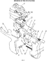
FIG. 1 is an exploded structural view of a gun-shaped ear piercing instrument according to a first embodiment of the present application; -
FIG. 2 is a perspective structural view of the gun-shaped ear piercing instrument according to the first embodiment of the present application; -
FIG. 3 is a sectional structural view of the gun-shaped ear piercing instrument according to the first embodiment of the present application; -
FIG. 4 is a state diagram in which studs and stud bases of the gun-shaped ear piercing instrument are mounted according to the first embodiment of the present application; -
FIG. 5 is a state diagram of the gun-shaped ear piercing instrument after finishing an idle stroke according to the first embodiment of the present application; -
FIG. 6 is a state diagram of the gun-shaped ear piercing instrument after finishing an aiming stroke according to the first embodiment of the present application; -
FIG. 7 is a state diagram of the gun-shaped ear piercing instrument after finishing a piercing stroke according to the first embodiment of the present application; -
FIG. 8 is a schematic diagram of a reset state of the gun-shaped ear piercing instrument according to the first embodiment of the present application; -
FIG. 9 is a schematic diagram of a spring locking piece and an unlocking trigger of the gun-shaped ear piercing instrument according to the first embodiment of the present application; -
FIG. 10 is an exploded structural view of a stud mounting portion of the gun-shaped ear piercing instrument according to the first embodiment of the present application; -
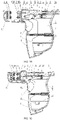
FIG. 11 is an exploded structural view of a gun-shaped ear piercing instrument according to a second embodiment of the present application; -
FIG. 12 is a perspective structural view of the gun-shaped ear piercing instrument according to the second embodiment of the present application; -
FIG. 13 is a sectional structural view of the gun-shaped ear piercing instrument according to the second embodiment of the present application; -
FIG. 14 is a state diagram in which a stud and a stud base of the gun-shaped ear piercing instrument are mounted according to the second embodiment of the present application; -
FIG. 15 is a state diagram of the gun-shaped ear piercing instrument after finishing an aiming stroke according to the second embodiment of the present application; -
FIG. 16 is a state diagram of the gun-shaped ear piercing instrument after finishing a piercing stroke according to the second embodiment of the present application; -
FIG. 17 is a schematic diagram of a reset state of the gun-shaped ear piercing instrument according to the second embodiment of the present application; -
FIG. 18 is a structural diagram of a first type of stud mounting portion of the gun-shaped ear piercing instrument according to the second embodiment of the present application; -
FIG. 19 is a structural diagram of a second type of stud mounting portion of the gun-shaped ear piercing instrument according to the second embodiment of the present application; and -
FIG. 20 is a structural diagram of a third type of stud mounting portion of the gun-shaped ear piercing instrument according to the second embodiment of the present application.
in which:
1: Front portion; 1a: Front piece; 1b: Back piece; 1c: Stop pin; 1d: Stop pin; 1e: Stop pin; 1f: Stopper; 2: Rear portion; 2a: Hollow tube; 2b: Notch; 2c: Stop groove; 2d: Stop groove; 2e: Stop groove; 2f: Blocking piece; 2g: End face of hollow tube; 2h: Straight slot; 3: Firing pin; 3a: Tail hook; 3b: Ring groove; 4: Firing spring; 5: Spring locking piece; 5a: Torsion spring; 5b: Triggering end; 5c: Locking end; 6: Unlocking trigger; 6a: Torsion spring; 6b: Side baffle; 6c: Trigger boss; 7: Track; 7a: Front slot; 8: Handle return spring; 9: Stud base mounting portion; 9a: Stud base; 10: Stud mounting portion; 10a: Stud; 10b: Stud holder; 10b1: Clamping piece; 10b2: Clamping piece; 10c: Stud tip; 10d: elastic track; 10e: Insert; 10f: Slit; 10g: Stud head; 10h: Flute; 11: fixing portion; 11a: fixing portion slot; 11b: Fixing portion return spring; 12: Clearance; and 13: Blister box. - As shown in
FIGS. 1 to 20 , according to an embodiment of the present application, a gun-shaped ear piercing instrument is provided, including afront portion 1 and arear portion 2, which are sleeved together and can move relatively. Atrack 7, having afront slot 7a for mounting a studbase mounting portion 9 disposed on one end thereof away from therear portion 2, as well as afixing portion 11 for mounting astud mounting portion 10 disposed thereon in a sliding manner, is disposed on thefront portion 1. A firing device corresponding to thefixing portion 11 is disposed on therear portion 2. Thefront portion 1 includes a grip having anunlocking trigger 6 disposed on a front side thereof, an elastic reset device as well as an aiming stroke restrainer are disposed between thefront portion 1 and therear portion 2, the aiming stroke restrainer is configured to restrain the firing device so as to help the firing device to move to an aiming position when firing device is in an aiming stroke, and theunlocking trigger 6 is configured to trigger the firing device to enter an piercing stroke for piercing the earlobe. - The
front portion 1 and therear portion 2 of the gun-shaped ear piercing instrument are reset by the elastic reset device, and the aiming stroke is confined by the aiming stroke restrainer, so that the gun-shaped ear piercing instrument can stably be stopped at the aiming position after entering the aiming stroke to meet the requirement of keeping a first ear piercing instrument that aims at the earlobe still, and the firing device is triggered by the separate unlockingtrigger 6 to enter the piercing stroke to make astud 10a pierce through the earlobe. Since the unlockingtrigger 6 is located at a front side of the grip of thefront portion 1, the unlockingtrigger 6 when pulled may be held and triggered by other fingers except the thumb. Slight hand motion may effectively avoid the problem that the first ear piercing instrument deviates from a piercing position in the process of triggering with the thumb, and ensure that two gun-shaped ear piercing instruments operate at the same time to make the piercing position more accurate and hardly deviate from the piercing position, thus improving the convenience and accuracy of ear piercing operations. - The gun-shaped ear piercing instrument according to the present application is of a gun-shaped structure, in which the stud
base mounting portion 9 and thestud mounting portion 10 are mounted on a gun barrel of thefront portion 1, thus piercing the ears easily. The grip according to the present application is formed on a gun handle, where the grip consists of two portions, namely a grip of thefront portion 1 and a grip of therear portion 2 which are sleeved together to form a complete grip. Since the unlockingtrigger 6, with its position similar to that of a trigger of a gun, is disposed on the grip of thefront portion 1, the unlockingtrigger 6 when pulled may be operated directly by the index finger in the same way as the gun, so that the unlocking trigger may be pulled more smoothly and ergonomically. Moreover, the motion of the index finger is only to pull the trigger slightly, so the motion is relatively slight, which can keep the overall stability and balance of the gun-shaped ear piercing instrument and thus effectively ensure the accuracy and reliability of the ear piercing operation. - The elastic reset device is disposed between the
front portion 1 and therear portion 2 to ensure that the two portions may be kept away from a predetermined position without external force, so that the firing device on therear portion 2 is kept away from a position where thestud 10a is located before the operation of the gun-shaped ear piercing instrument starts, which facilitates operations such as mounting thestud 10a, and can reserve the movable space required for a next aiming stroke at the same time. - In the present application, the elastic reset device includes a
handle return spring 8 with one end connected to thefront portion 1 and the other end connected to therear portion 2, so that thefront portion 1 and therear portion 2 are connected together to form a complete gun-shaped structure. A spring sleeve, in which thehandle return spring 8 is sleeved and fixed, is disposed on therear portion 2, and a spring link, to which thehandle return spring 8 is connected, is disposed on thefront portion 1. When thehandle spring 8 is in a naturally extended state, thefront portion 1 and therear portion 2 are sleeved together and partially overlap, so that thefront portion 1 and therear portion 2 can be integrated without falling out of a sleeve. Thefront portion 1 and therear portion 2 can be directly held to close when needed. After overcoming the elastic action of thehandle spring 8, thefront portion 1 and therear portion 2 are closed, with an overlapped portion thereof enlarging and the overall width of a holding portion reducing. In this case, thehandle return spring 8 has an elastic force to expand outward, so when the external force disappears, thehandle return spring 8 can spring thefront portion 1 and therear portion 2 apart, making the two restore the initial state. - The
track 7 is fixedly disposed on thefront portion 1. Thetrack 7 may be designed and machined separately from and then fixedly connected to thefront portion 1, or may be directly molded on thefront portion 1. Thefront slot 7a is disposed at one end of thetrack 7, and the fixingportion 11 is disposed at the other end. A fixingportion slot 11a, on which thestud mounting portion 10 is fixedly disposed, is disposed on the fixingportion 11. The fixingportion 11 is disposed on thetrack 7 in a sliding manner, so as to adjust its relative position with thefront slot 7a. Because of the relative movement thereof, the fixingportion 11 and thefront slot 7a can be configured to respectively mount the studbase mounting portion 9 and thestud mounting portion 10 which are separated. Compared with a cassette design in which the studbase mounting portion 9 and thestud mounting portion 10 are integrated, the separated structure is less costly to design and manufacture, but requires higher machining accuracy to ensure that the studbase mounting portion 9 and thestud mounting portion 10 are in place at the same time. The above mounting structure of thefront slot 7a and the fixingportion 11 also applies to the cassette in which the studbase mounting portion 9 and thestud mounting portion 10 are integrated. - A
spring locking piece 5, which is disposed on a firing path of the firing device for locking the firing device, is disposed in therear portion 2, and the unlockingtrigger 6 is in drive connection withspring locking piece 5 to drive thespring locking piece 5 to unlock the firing device. The unlockingtrigger 6 is disposed on thefront portion 1, thespring locking piece 5 is disposed on therear portion 2, thespring locking piece 5 needs to keep the firing device locked all the time before the firing device reaches the aiming position, and the unlockingtrigger 6 needs to drive thespring locking piece 5 to unlock the firing device locked by thespring locking piece 5 after the firing device reaches the aiming position to ensure that the firing device can fire thestud 10a, so the driving relation between the unlockingtrigger 6 and thespring locking piece 5 may be set in such way that the unlockingtrigger 6 cannot drive thespring locking piece 5 if the unlockingtrigger 6 and thespring locking piece 5 do not reach a driving position before the firing device reaches the aiming position. The driving relation may also be set in such way that a drive structure may be formed between the unlockingtrigger 6 and thespring locking piece 5 before the firing device reaches the aiming position, but the unlockingtrigger 6 is limited by other structures and thus cannot drive thespring locking piece 5. Only when the firing device reaches the aiming position will the unlockingtrigger 6 be released by limiting structures. Only in this case, the unlockingtrigger 6 can drive thespring locking piece 5. Such structure can effectively avoid the unlockingtrigger 6 from falsely triggering thespring locking piece 5, and improve the operation safety, reliability and accuracy of the gun-shaped ear piercing instrument. - In the present application, the
spring locking piece 5 may be rotatably disposed on therear portion 2, atorsion spring 5a for returning thespring locking piece 5 is disposed between thespring locking piece 5 and therear portion 2, and thespring locking piece 5 includes a locking end 5c configured to lock the firing device and a triggeringend 5b configured to unlock together with the unlockingtrigger 6. Thespring locking piece 5 is similar to a lever structure, with a center section thereof mounted on therear portion 2 through thetorsion spring 5a, and the torque of thetorsion spring 5a provides a locking force for locking the firing device. One end of thespring locking piece 5 forms a stop end that may be clamped on the firing path of the firing device to lock the firing device, while the other end thereof may form a driving relation with the unlockingtrigger 6 after the firing device reaches the aiming position, and the firing device is unlocked under the drive of the unlockingtrigger 6. - A
hollow tube 2a is disposed on the top of therear portion 2, the firing device includes afiring pin 3 and afiring spring 4, which are mounted in thehollow tube 2a, and both ends of thefiring spring 4 are elastically propped against thefiring pin 3 and thefiring spring 4 respectively. A strip-shapednotch 2b, below which thespring locking piece 5 is disposed, is disposed below thehollow tube 2a, and the locking end 5c of thespring locking piece 5 extends into thenotch 2b to lock the firing device together with thefiring pin 3. - A
ring groove 3b is disposed on thefiring pin 3, and the locking end 5c of thespring locking piece 5 is snapped into thering groove 3b when thespring locking piece 5 is locked, and is detached from thering groove 3b when thespring locking piece 5 is unlocked. Thering groove 3b may also be a recess, provided that the locking end 5c of thespring locking piece 5 can be snapped into the recess to stop thefiring pin 3. - The
firing pin 3 includes a major-diameter section disposed at a front end thereof, as well as a minor-diameter section disposed at a rear end thereof and coming out from thehollow tube 2a, thering groove 3b is disposed at the major-diameter section, one end of thefiring spring 4 is propped against one end of the major-diameter section connected to the minor-diameter section, while the other end thereof is propped against an end wall of thehollow tube 2a. Thefiring pin 3 is of a structure in which the major-diameter section and the minor-diameter section are fitted to each other, which may form a stop step by different diameters of the major-diameter section and the minor-diameter section, so that one end of thefiring spring 4 may be stopped on the stop step while the other end thereof may be stopped on the end wall of thehollow tube 2a. A hole, through which the minor-diameter section partially comes out of thehollow tube 2a, is formed on the end wall of thehollow tube 2a, so that thefiring pin 3 may be operated easily by the minor-diameter section. After firing, thefiring pin 3 can be returned to its original position by operating the minor-diameter section, and thespring locking piece 5 can be snapped into thering groove 3b of thefiring pin 3 again, thus locking thefiring pin 3 for the next piercing operation. - A
tail hook 3a suitable for holding is disposed on a tail of thefiring pin 3 coming out of thehollow tube 2a. In practice, an eye splice may also be mounted on thetail hook 3a, so that thetail hook 3a can be pulled back more easily. When thetail hook 3a is pulled back and thefiring pin 3 moves back to press thefiring spring 4 to a certain position, thespring locking piece 5 is snapped into thering groove 3b on thefiring pin 3 to tighten thefiring spring 4, so that thefiring pin 3 is in a state to be fired. When thefiring pin 3 moves back to be fired, thestud mounting portion 10 is inserted into the fixingportion slot 11a of the fixingportion 11, and thefiring pin 3 is just aimed at thestud 10a in anelastic track 10d. - A mounting groove, having the unlocking
trigger 6 disposed therein, is disposed on a front side of the grip of thefront portion 1, a first end of the unlockingtrigger 6 is hinged to thefront portion 1 and connected to thefront portion 1 through atorsion spring 6a, while a second end thereof is blocked on an inner wall of thefront portion 1. A trigger boss 6c is disposed on the top of the unlockingtrigger 6, and aside catch 6b is disposed on at least one side of the unlockingtrigger 6; and astraight slot 2h is disposed on a lower side of therear portion 2, the trigger boss 6c is at least partially disposed in thestraight slot 2h, and theside catch 6b is blocked outside thestraight slot 2h. The mounting groove is located at the front side of the grip, and its position is similar to that of a trigger of a pistol, allowing a more pistol-like structure and easier manual operations. The first end of the unlockingtrigger 6 is hinged to thefront portion 1, while the second end thereof is in a cantilever position and pressed against the inner wall of thefront portion 1 under the elastic action of thetorsion spring 6a. Therefore, before being operated by hand, the unlockingtrigger 6 will not trigger thespring locking piece 5 under the elastic action of thetorsion spring 6a to release thespring locking piece 5. The first end of the unlockingtrigger 6 is hinged, and is provided with an arc-shaped structure at an end, which can provide a larger space for the unlockingtrigger 6 to rotate without interference with thefront portion 1, and thus more effectively ensure that the unlockingtrigger 6 has enough release ability and larger moving range to release thespring locking piece 5 effectively. - In this embodiment, a hook is disposed at an end of the second end of the unlocking
trigger 6, and an overhead hook is further disposed at a position where a wall of the mounting groove of thefront portion 1 is fitted to the second end of the unlockingtrigger 6. The hook of the unlockingtrigger 6 is hooked to the overhead hook under the action of thetorsion spring 6a, thus effectively preventing the second end of the unlockingtrigger 6 from falling out of the mounting groove, and improving the stability and reliability of the mounting structure of the unlockingtrigger 6 in thefront portion 1. - Optionally, the
side catch 6b is disposed on the side of the trigger boss 6c. Theside catch 6b are disposed on both sides of the trigger boss 6c respectively, which can ensure that the wall of thestraight slot 2h uniformly blocks the trigger boss 6c. The trigger boss 6c is provided to ensure that the unlockingtrigger 6 only partially enters thestraight slot 2h, and a raised structure of the trigger boss 6c forms a driving relation with thespring locking piece 5 more easily, so as to trigger and release thespring locking piece 5. - A
blocking piece 2f protruding towards the unlockingtrigger 6 is further disposed on the lower side of therear portion 2, thespring locking piece 5 is disposed at a rear side of theblocking piece 2f. Before thefront portion 1 and therear portion 2 are completely closed, the trigger boss 6c of the unlockingtrigger 6 is located at theblocking piece 2f, and the unlockingtrigger 6 is pressed against the inner wall of thefront portion 1 by theblocking piece 2f. After thefront portion 1 and therear portion 2 are completely closed, the trigger boss 6c of the unlockingtrigger 6 is staggered from theblocking piece 2f, theside catch 6b passes over the protrudedblocking piece 2f and is fitted to the triggeringend 5b of thespring locking piece 5. In this case, the unlockingtrigger 6 can fully rotate to a proper position, and the trigger boss 6c of the unlockingtrigger 6 can drive the triggeringend 5b of thespring locking piece 5 to move and in turn drive thespring locking piece 5 to rotate, so that the locking end 5c of thespring locking piece 5 is moved away from a locked position to unlock the firing device and release thefiring spring 4, so as to complete the firing process. - The
blocking piece 2f is shorter than the aiming stroke in length, so that the trigger boss 6c of the unlockingtrigger 6 can completely stagger from theblocking piece 2f and reaches a position where thespring locking piece 5 is located after the aiming stroke is finished, so as to unlock thespring locking piece 5 in time and effectively. - The
rear portion 2 is sleeved in thefront portion 1, and the aiming stroke restrainer includes stop pins disposed on thefront portion 1, and stop grooves disposed on therear portion 2. The stop pins are disposed on an upper portion and a lower portion of a fitting portion of thefront portion 1 and therear portion 2 respectively, and the stop grooves are disposed at corresponding positions of therear portion 2, and the stroke of the stop pin in the stop groove is the aiming stroke. - Specifically, the
front portion 1 includes a front piece 1a and arear piece 1b, which are spliced to form thefront portion 1. The stop pins 1d and 1e are disposed on thefront portion 1, and thestop grooves rear portion 2, where thestop pin 1d can slide in thestop groove 2d, the stop pin 1e can slide in thestop groove 2e, and thestop groove 2d is parallel to thestop groove 2e. The structure in which the two sets of stop pins and stop grooves are fitted to each other can effectively guide the movement of therear portion 2 relative to thefront portion 1, thus ensuring the accuracy of the movement direction of therear portion 2 and the accuracy of the ear piercing operation. The stroke of the stop pin in the stop groove is the aiming stroke, which can effectively confine the length and end point of the aiming stroke, and ensure the accuracy of the aiming position, ensure that the firing device stops in time after reaching the aiming position, to meet the requirement of keeping a first ear piercing instrument that aims at the earlobe still. - As shown in
FIGS. 1 to 10 , according to the first embodiment of the present application, the fixingportion 11 and therear portion 2 are disposed separately, the stop pin 1c is disposed on thefront portion 1, thestop groove 2c in which the stop pin 1c can slide is disposed on therear portion 2, and a fixingportion return spring 11b, with one end hooked to the stop pin 1c and the other end connected to the fixingportion 11, is connected between the fixingportion 11 and thefront portion 1. - In this embodiment, after the firing device completes the firing operation and returns back, the fixing
portion return spring 11b can pull the fixingportion 11 back, allowing the fixingportion 11 to return to its original position. - The
front portion 1 is further provided with a stopper 1f which is stopped between the fixingportion 11 and an end of thehollow tube 2a, so that aclearance 12 is formed between the fixingportion 11 and anend face 2g of the hollow tube while the fixingportion return spring 11b generates a pretensioning force before thefront portion 1 and therear portion 2 are closed. - The
clearance 12 between the fixingportion 11 and theend face 2g of the hollow tube makes ablister box 13, which serves as a material for packaging the studbase mounting portion 9 and thestud mounting portion 10, go down into place, so that the studbase mounting portion 9 and thestud mounting portion 10 can be snapped into thefront slot 7a and the fixingportion slot 11a simultaneously. - The gun-shaped ear piercing instrument further includes the
stud mounting portion 10 having aelastic track 10d, astud holder 10b and astud 10a, the tubularelastic track 10d is tubular and includes aradial slit 10f extending in the movement direction of thestud 10a. Theslit 10f allows theelastic track 10d to have a certain elastic force to properly clamp thestud holder 10b mounted in theelastic track 10d, so that the stud holder may be stably fixed without moving back and forth, and may also move under the action of thefiring pin 3 with little friction. Thestud holder 10b includes two clamping pieces 10b1 and 10b2, which, when closed, can clamp astud head 10g in the middle to only expose astud tip 10c. - In this embodiment, the whole piercing process of the gun-shaped ear piercing instrument includes three strokes, namely a first stroke (idle stroke) where the
front portion 1 and therear portion 2 of the gun-shaped ear piercing instrument are closed to eliminate theclearance 12, a second stroke (aiming stroke) where thestud mounting portion 10 and the studbase mounting portion 9 are closed to each other, and a third stroke (piercing stroke) where the spring and thefiring pin 3 drive thestud 10a to move forward. - When there is a need of ear piercing, a lower portion of the gun-shaped structure is held by hand, and the
handle return spring 8 is pressed by closing the hand, so that therear portion 2 moves toward thefront portion 1 to finish the first stroke (idle stroke) equivalent to the width of theclearance 12, making theend face 2g of the hollow tube propped against the fixingportion 11. When therear portion 2 continues to move forward, theend face 2g of the hollow tube drives the fixingportion 11 to finish the second stroke (aiming stroke) to the end, so that thestud tip 10c of thestud 10a on thestud mounting portion 10 is close to the earlobe and kept still. This is the process of aiming, positioning and keeping still before ear piercing. - When pulled by the index finger, the unlocking
trigger 6 rotates to trigger thespring locking piece 5 to move down to release thefiring spring 4, so that thefiring pin 3 drive thestud holder 10b in theelastic track 10d and thestud 10a wrapped therein to move in theelastic track 10d, and thestud 10a is inserted into astud base 9a after piercing through the earlobe. This stroke is the third stroke (piercing stroke) driven by the spring and thefiring pin 3. Thus it can be seen that thestud 10a takes three strokes from approaching to piercing the earlobe. - When the above operations are completed, the stud
base mounting portion 9 is designed as a mechanism in which thestud base 9a will be detached from the studbase mounting portion 9 when thestud 10a is inserted into thestud base 9a, thestud base 10 is also designed as a mechanism in which thestud 10a will be detached from thestud holder 10b once thestud holder 10b is detached from theelastic track 10d (thestud holder 10b is formed by closing the two clamping pieces 10b1 and 10b2 together, and will be automatically separated once detached from theelastic track 10d), so when thestud 10a is inserted into thestud base 9a after piercing through the earlobe, thestud base 9a and thestud 10a will be detached from the studbase mounting portion 9 and theelastic track 10d at the same time and both left on the earlobe. In this way, the entire ear piercing process is completed. - As shown in
FIGS. 11 to 20 , according to a second embodiment of the present application, a fixingportion 11 is disposed at an end of ahollow tube 2a and forms an integrated structure with thehollow tube 2a. - In this embodiment, a stud
base mounting portion 9 and astud mounting portion 10 are taken out of ablister box 13 and put into the gun-shaped ear piercing instrument respectively, so there is noclearance 12 between the fixingportion 11 and afiring pin 3, and the fixingportion 11 is connected to anend face 2g of the hollow tube. Thus, one stroke is omitted, and the gun becomes a two-stroke gun-shaped ear piercing instrument. At the same time, since the fixingportion 11 is fixed on therear portion 2, a fixingportion return spring 11b is also omitted, which simplifies the structure of the gun-shaped ear piercing instrument, and reduces the structural complexity and the machining cost. - The gun-shaped ear piercing instrument further includes a
stud mounting portion 10 having twoelastic tracks 10d, astud 10a which can slide in theelastic track 10d is disposed in each track, and thestud mounting portion 10 is of a centrosymmetric structure. - In this embodiment, the fixing
portion 11 is provided at a front end of thehollow tube 2a of therear portion 2. A fixingportion slot 11a, to which thestud mounting portion 10 is fixed, is disposed on the fixingportion 11. There are twoelastic tracks 10d and inserts 10e on thestud mounting portion 10. Eachelastic track 10d is of a tubular structure having at least oneslit 10f running through, and thestud 10a is directly mounted in theelastic track 10d. - Two
stud bases 9a are mounted on the studbase mounting portion 9, and twoelastic tracks 10d each having astud 10a mounted respectively therein are mounted on thestud mounting portion 10. When the gun-shaped ear piercing instrument completes a first ear piercing operation, after rotating 180 degrees, the studbase mounting portion 9 and the studbase mounting portion 10 may be mounted on the gun-shaped ear piercing instrument to complete a second ear piercing operation. In this way, the cost is further reduced. - Each
elastic track 10d is of a tubular structure having a cylindrical inner cavity as well as at least two straight slots axially extending, and at least one straight slot runs through a tube wall of the tubular structure. - Since an inner cavity of the tubular structure is cylindrical, the
stud head 10g of thestud 10a is cylindrical. With thecylindrical stud head 10g, thestud 10a can be directly mounted in theelastic track 10d without thestud holder 10b, and thestud tip 10c keeps moving forward stably when thestud 10a moves in theelastic track 10d, thus reducing the cost of thestud 10a. - In one of the embodiments of the
stud mounting portion 10, the two straight slots of the tubular structure are located at both ends of the same diameter of the tubular structure respectively, and run through tube wall of the tubular structure. - In another embodiment of the
stud mounting portion 10, the two straight slots of the tubular structure are located at both ends of the same diameter of the tubular structure respectively, where one straight slot runs through the tube wall of the tubular structure, and the other straight slot, having a slot depth less than a wall thickness of the tubular structure, is located on an outer wall or an inner wall of the tubular structure, thus forming aflute 10h at a position which is a hinge point of elastic deformation of an elastic tube. - With any of the above three structures of the
elastic track 10d, thestud head 10g varying in diameter in a certain range can be stably mounted in theelastic track 10d, and can move back and forth while keeping thestud tip 10c of thestud 10a from swinging, thereby reducing the machining accuracy of thestud 10a and the production cost and improving the yield. - When there is a need of ear piercing, the lower portion of the gun-shaped structure is held by hand, and the
handle return spring 8 is pressed by closing the hand, so that therear portion 2 moves toward thefront portion 1, and the fixingportion 11 and thefiring pin 3 move forward for an aiming stroke accordingly, so that thestud tip 10c of thestud 10a on thestud mounting portion 10 is close to the earlobe and keeps still. This is the process of aiming, positioning and keeping still before ear piercing. - When the index finger pulls the unlocking
trigger 6, the unlockingtrigger 6 rotates to trigger thespring locking piece 5 to move downward to release thefiring spring 4, so that thefiring pin 3 drives thestud 10a in theelastic track 10d to move forward to insert into thestud base 9a after piercing through the earlobe. - The side catches 6b preventing false triggering are disposed on side faces of the unlocking
trigger 6, and the protruded blockingpieces 2f are disposed on therear portion 2. Before thefront portion 1 and therear portion 2 are completely closed, if the unlockingtrigger 6 is accidentally pulled, theside catch 6b will be blocked by the protrudedblocking piece 2f on therear portion 2 to limit the rotation of the unlockingtrigger 6, thereby avoiding false triggering of thespring locking piece 5. Only when thefront portion 1 and therear portion 2 are completely closed will theside catch 6b pass over the protrudedblocking piece 2f. In this case, the unlockingtrigger 6 can fully rotate to a proper position to drive thespring locking piece 5 to rotate and release thefiring spring 4, so as to complete the firing process. - After that, the hand is unlocked, and the
rear portion 2 moves back under the action of thehandle return spring 8, and thestud 10a is detached from theelastic track 10d. The studbase mounting portion 9 is designed as a mechanism in which thestud base 9a will be detached from the studbase mounting portion 9 when thestud 10a is pierced into thestud 9a, so when thestud 10a is pierced into thestud base 9a after piercing through the earlobe, thestud base 9a and thestud 10a will be detached from the studbase mounting portion 9 and thestud mounting portion 10 at the same time and both left on earlobe. In this way, the entire ear piercing process is completed. - It is readily understood by those of skill in the art that the above advantageous embodiments may be freely combined and superimposed without conflict.
- Those described above are merely preferred embodiments of the present application, and are not intended to limit the present application. Any modifications, equivalent substitutions and improvements made without departing from the spirit and principle of the present application shall fall into the protection scope of the present application. Those described above are merely preferred embodiments of the present application. It should be noted that a number of improvements and variations may be made by those of ordinary skill in the art without departing from the technical principles of the present application, and such improvements and variations shall also fall into the protection scope of the present application.
Claims (17)
- a gun-shaped ear piercing instrument, comprising a front portion and a rear portion, wherein the front portion and the rear portion are sleeved together and are able to move relative to each other, wherein a track is disposed on the front portion, a front slot for mounting a mounting portion for a stud base is disposed on one end of the track away from the rear portion, a fixing portion for mounting a mounting portion for a stud is disposed on the track in a slidable manner; a firing device corresponding to the fixing portion is disposed on the rear portion; and the front portion comprises a grip wherein an unlocking trigger is disposed on a front side of the grip, an elastic reset device and an aiming stroke restrainer are disposed between the front portion and the rear portion, the aiming stroke restrainer is configured to restrain the firing device so as to help the firing device to move to an aiming position when firing device is in an aiming stroke, and the unlocking trigger is configured to trigger the firing device to enter an piercing stroke for piercing the earlobe.
- The gun-shaped ear piercing instrument according to claim 1, wherein a spring locking piece, which is disposed on a firing path of the firing device for locking the firing device, is disposed in the rear portion, and the unlocking trigger is in drive connection with the spring locking piece to drive the spring locking piece to unlock the firing device.
- The gun-shaped ear piercing instrument according to claim 2, wherein the spring locking piece is disposed on the rear portion, a torsion spring for returning the spring locking piece is disposed between the spring locking piece and the rear portion, and the spring locking piece comprises a locking end configured to lock the firing device and a triggering end configured to work with the unlocking trigger so as to unlock.
- The gun-shaped ear piercing instrument according to claim 2, wherein a hollow tube is disposed on the top of the rear portion, the firing device comprises a firing pin and a firing spring, which are mounted in the hollow tube, and both ends of the firing spring are elastically propped against the firing pin and the firing spring respectively; and a strip-shaped notch is disposed below the hollow tube, and the locking end of the spring locking piece extends into the notch, and is configured to work with the firing pin so as to lock the firing device.
- The gun-shaped ear piercing instrument according to claim 4, wherein a ring groove is disposed on the firing pin, and the locking end of the spring locking piece is snapped into the ring groove when the spring locking piece is locked, and is detached from the ring groove when the spring locking piece is unlocked.
- The gun-shaped ear piercing instrument according to claim 5, wherein the firing pin comprises a major-diameter section disposed at a front end thereof, as well as a minor-diameter section disposed at a rear end thereof and coming out from the hollow tube, the ring groove is disposed at the major-diameter section, one end of the firing spring is propped against one end of the major-diameter section connected to the minor-diameter section, while the other end thereof is propped against an end wall of the hollow tube.
- The gun-shaped ear piercing instrument according to claim 2, wherein a mounting groove, having the unlocking trigger disposed therein, is disposed on a front side of the grip of the front portion, a first end of the unlocking trigger is hinged to the front portion and connected to the front portion through a torsion spring, while a second end thereof is blocked on an inner wall of the front portion; a trigger boss is disposed on the top of the unlocking trigger, and a side catch is disposed on at least one side of the unlocking trigger; and a straight slot is disposed on a lower side of the rear portion, the trigger boss is at least partially disposed in the straight slot, and the side catch is blocked outside the straight slot.
- The gun-shaped ear piercing instrument according to claim 7, wherein a blocking piece protruding towards the unlocking trigger is further disposed on the lower side of the rear portion, the spring locking piece is disposed at a rear side of the blocking piece; before the front portion and the rear portion are completely closed, the trigger boss of the unlocking trigger is located at the blocking piece, and the unlocking trigger is pressed against the inner wall of the front portion by the blocking piece; after the front portion and the rear portion are completely closed, the trigger boss of the unlocking trigger is staggered from the blocking piece and is fitted to the triggering end of the spring locking piece; the unlocking trigger can be pulled, and the trigger boss of the unlocking trigger can drive the triggering end of the spring locking piece to move, so that the locking end of the spring locking piece is moved away from a locked position, so as to unlock the firing device.
- The gun-shaped ear piercing instrument according to claim 1, wherein the rear portion is sleeved in the front portion, and the aiming stroke restrainer comprises stop pins disposed on the front portion and stop grooves disposed on the rear portion; the stop pins are disposed on an upper portion and a lower portion of a fitting portion of the front portion and the rear portion respectively, and the stop grooves are disposed at corresponding positions of the rear portion, and the stroke of the stop pin in the stop groove is the aiming stroke.
- The gun-shaped ear piercing instrument according to claim 4, wherein the fixing portion and the rear portion are disposed separately, the stop pin is disposed on the front portion, the stop groove in which the stop pin can slide is disposed on the rear portion, and a fixing portion return spring, with one end hooked to the stop pin and the other end connected to the fixing portion, is connected between the fixing portion and the front portion.
- The gun-shaped ear piercing instrument according to claim 10, wherein the front portion is further provided with a stopper which is stopped between the fixing portion and an end of the hollow tube, so that a clearance is formed between the fixing portion and the hollow tube while the fixing portion return spring generates a pretensioning force before the front portion and the rear portion are closed.
- The gun-shaped ear piercing instrument according to claim 10, wherein the gun-shaped ear piercing instrument further comprises a stud mounting portion having an elastic track, a stud holder and a stud, and the elastic track is tubular and comprises a radial slit extending in the movement direction of the stud.
- The gun-shaped ear piercing instrument according to claim 4, wherein the fixing portion is disposed at the end of the hollow tube and forms an integrated structure with the hollow tube.
- The gun-shaped ear piercing instrument according to claim 13, wherein the gun-shaped ear piercing instrument further comprises a stud mounting portion having two elastic tracks, a stud which can slide in the elastic track is disposed in each track, and the stud mounting portion is of a centrosymmetric structure.
- The gun-shaped ear piercing instrument according to claim 14, wherein the elastic track is of a tubular structure having a cylindrical inner cavity, wherein the tubular structure is equipped with at least two straight slots extending in an axial direction, and at least one straight slot runs through a tube wall of the tubular structure.
- The gun-shaped ear piercing instrument according to claim 15, wherein the two straight slots of the tubular structure are located at both ends of the same diameter of the tubular structure respectively, and run through the tube wall of the tubular structure.
- The gun-shaped ear piercing instrument according to claim 15, wherein the two straight slots of the tubular structure are located at both ends of the same diameter of the tubular structure respectively, where one straight slot runs through the tube wall of the tubular structure, and the other straight slot, having a slot depth less than a wall thickness of the tubular structure, is located on an outer wall or an inner wall of the tubular structure.
Applications Claiming Priority (2)
| Application Number | Priority Date | Filing Date | Title |
|---|---|---|---|
| CN202010183292.2A CN111358125B (en) | 2020-03-16 | 2020-03-16 | Ear hole punching gun |
| PCT/CN2020/084091 WO2021184460A1 (en) | 2020-03-16 | 2020-04-10 | Ear piercing gun |
Publications (2)
| Publication Number | Publication Date |
|---|---|
| EP4029400A1 true EP4029400A1 (en) | 2022-07-20 |
| EP4029400A4 EP4029400A4 (en) | 2022-12-21 |
Family
ID=71198471
Family Applications (1)
| Application Number | Title | Priority Date | Filing Date |
|---|---|---|---|
| EP20926330.0A Pending EP4029400A4 (en) | 2020-03-16 | 2020-04-10 | Ear piercing gun |
Country Status (4)
| Country | Link |
|---|---|
| US (1) | US11751646B2 (en) |
| EP (1) | EP4029400A4 (en) |
| CN (1) | CN111358125B (en) |
| WO (1) | WO2021184460A1 (en) |
Families Citing this family (2)
| Publication number | Priority date | Publication date | Assignee | Title |
|---|---|---|---|---|
| CN113384046B (en) * | 2021-06-08 | 2022-11-11 | 程波 | Dual-purpose puncture gun |
| CN114190665B (en) * | 2022-01-04 | 2022-10-25 | 程波 | Manual ear hole punching gun |
Family Cites Families (14)
| Publication number | Priority date | Publication date | Assignee | Title |
|---|---|---|---|---|
| US4068668A (en) * | 1975-09-08 | 1978-01-17 | Concept Marketing, Inc. | Ear lobe piercing device |
| GB2187960A (en) * | 1986-02-14 | 1987-09-23 | Brian Mander | Ear piercing |
| DE3718256A1 (en) * | 1987-05-30 | 1988-12-08 | Wittek Margarete | DEVICE FOR SHOTING IN EAR PLUGS INTO OHRLAEPPCHEN |
| JP2538851B2 (en) * | 1991-02-19 | 1996-10-02 | 剛 中嶋 | Piercing punch |
| US5360434A (en) | 1992-08-28 | 1994-11-01 | Inverness Corporation | Non-removable earring and clutch ear piercing instrument |
| US5263960A (en) * | 1992-11-12 | 1993-11-23 | Inverness Corporation | Integrated disposable ear piercing earring and clutch cartridge and ear piercing instrument for use therewith |
| US5690665A (en) * | 1996-02-13 | 1997-11-25 | Inverness Corporation | Rotatable ear piercing cartridge assembly |
| JPH1023909A (en) * | 1997-04-09 | 1998-01-27 | Central Medic:Kk | Piercer |
| JP3021408B2 (en) | 1997-12-05 | 2000-03-15 | 株式会社ナック | Piercing perforator |
| US6599306B1 (en) * | 2000-10-17 | 2003-07-29 | Vladimir Reil | Ear piercing cartridge and stud gun system |
| CN200994481Y (en) * | 2007-01-15 | 2007-12-26 | 雷龙兴 | Improved structure of earing-aperture punch |
| CN204671199U (en) | 2015-05-29 | 2015-09-30 | 熊平 | Manual propelling Ear perforator |
| KR101785088B1 (en) | 2015-12-03 | 2017-10-12 | 주식회사 노바메디 | Piercing Device |
| US10798999B2 (en) | 2017-06-01 | 2020-10-13 | Goran Reil | Overhanging jaw cartridge for body piercing instrument |
-
2020
- 2020-03-16 CN CN202010183292.2A patent/CN111358125B/en active Active
- 2020-04-10 EP EP20926330.0A patent/EP4029400A4/en active Pending
- 2020-04-10 WO PCT/CN2020/084091 patent/WO2021184460A1/en unknown
- 2020-04-10 US US17/772,076 patent/US11751646B2/en active Active
Also Published As
| Publication number | Publication date |
|---|---|
| EP4029400A4 (en) | 2022-12-21 |
| WO2021184460A1 (en) | 2021-09-23 |
| CN111358125B (en) | 2021-03-23 |
| CN111358125A (en) | 2020-07-03 |
| US11751646B2 (en) | 2023-09-12 |
| US20230000221A1 (en) | 2023-01-05 |
Similar Documents
| Publication | Publication Date | Title |
|---|---|---|
| EP4029400A1 (en) | Ear piercing gun | |
| EP2314209B1 (en) | Puncture needle cartridge | |
| US6459887B2 (en) | Foldable portable telephone | |
| US20070056170A1 (en) | Double ended knife | |
| KR960010995B1 (en) | Device for piercing the ear-lobes | |
| US5360434A (en) | Non-removable earring and clutch ear piercing instrument | |
| US5389105A (en) | Ear piercing apparatus with rotatably displaceable push rod | |
| US6048355A (en) | Ear piercing cartridges | |
| US11806883B2 (en) | Folding knife | |
| US20050246901A1 (en) | Reciprocating power tool | |
| JP2001259029A (en) | Safe indwelling needle | |
| JPH0123742Y2 (en) | ||
| JP2017108822A (en) | Hook for safety belt for high-place work | |
| CN113804054B (en) | Instantaneous percussion self-locking type anti-riot fork | |
| JPH09215694A (en) | Rotatable cartridge assembly piercing ear | |
| JP2970900B2 (en) | Telescopic rod | |
| JP2004524991A (en) | Writing implement | |
| US4897950A (en) | Locking device for the crane of a revolver | |
| WO2023130531A1 (en) | Manual ear-piercing gun | |
| JP3940370B2 (en) | Side lock device | |
| JPH0634761B2 (en) | Earlobe punch | |
| KR930004845Y1 (en) | Joint for folding ladder | |
| JP2605467Y2 (en) | Bazooka crackers | |
| IT202100000935U1 (en) | A CARTRIDGE FOR THE APPLICATION OF EARRINGS AND/OR PIERCING | |
| JP2020092937A (en) | Stick self-supporting device |
Legal Events
| Date | Code | Title | Description |
|---|---|---|---|
| STAA | Information on the status of an ep patent application or granted ep patent |
Free format text: STATUS: THE INTERNATIONAL PUBLICATION HAS BEEN MADE |
|
| PUAI | Public reference made under article 153(3) epc to a published international application that has entered the european phase |
Free format text: ORIGINAL CODE: 0009012 |
|
| STAA | Information on the status of an ep patent application or granted ep patent |
Free format text: STATUS: REQUEST FOR EXAMINATION WAS MADE |
|
| 17P | Request for examination filed |
Effective date: 20220412 |
|
| AK | Designated contracting states |
Kind code of ref document: A1 Designated state(s): AL AT BE BG CH CY CZ DE DK EE ES FI FR GB GR HR HU IE IS IT LI LT LU LV MC MK MT NL NO PL PT RO RS SE SI SK SM TR |
|
| A4 | Supplementary search report drawn up and despatched |
Effective date: 20221123 |
|
| RIC1 | Information provided on ipc code assigned before grant |
Ipc: A44C 7/00 20060101AFI20221117BHEP |
|
| DAV | Request for validation of the european patent (deleted) | ||
| DAX | Request for extension of the european patent (deleted) | ||
| GRAP | Despatch of communication of intention to grant a patent |
Free format text: ORIGINAL CODE: EPIDOSNIGR1 |
|
| STAA | Information on the status of an ep patent application or granted ep patent |
Free format text: STATUS: GRANT OF PATENT IS INTENDED |
|
| INTG | Intention to grant announced |
Effective date: 20240122 |
|
| GRAS | Grant fee paid |
Free format text: ORIGINAL CODE: EPIDOSNIGR3 |
|
| GRAA | (expected) grant |
Free format text: ORIGINAL CODE: 0009210 |
|
| STAA | Information on the status of an ep patent application or granted ep patent |
Free format text: STATUS: THE PATENT HAS BEEN GRANTED |