EP4029305B1 - Vorrichtung zur datenerfassung in einem funkzugangsnetz - Google Patents
Vorrichtung zur datenerfassung in einem funkzugangsnetz Download PDFInfo
- Publication number
- EP4029305B1 EP4029305B1 EP19769448.2A EP19769448A EP4029305B1 EP 4029305 B1 EP4029305 B1 EP 4029305B1 EP 19769448 A EP19769448 A EP 19769448A EP 4029305 B1 EP4029305 B1 EP 4029305B1
- Authority
- EP
- European Patent Office
- Prior art keywords
- measurement
- measurement request
- request
- determined
- requested
- Prior art date
- Legal status (The legal status is an assumption and is not a legal conclusion. Google has not performed a legal analysis and makes no representation as to the accuracy of the status listed.)
- Active
Links
Images


Classifications
-
- H—ELECTRICITY
- H04—ELECTRIC COMMUNICATION TECHNIQUE
- H04W—WIRELESS COMMUNICATION NETWORKS
- H04W24/00—Supervisory, monitoring or testing arrangements
- H04W24/10—Scheduling measurement reports ; Arrangements for measurement reports
-
- H—ELECTRICITY
- H04—ELECTRIC COMMUNICATION TECHNIQUE
- H04W—WIRELESS COMMUNICATION NETWORKS
- H04W24/00—Supervisory, monitoring or testing arrangements
- H04W24/08—Testing, supervising or monitoring using real traffic
Definitions
- radio access network data collection e.g. minimization of drive test data collection, and machine learning based optimization of networks.
- WO 2011/101026 A1 discloses that specific area information with a certain granularity is transmitted as part of the measurement request in order to adapt the data collection to the needs.
- Fig. 1 shows, by way of an example, a system architecture.
- a radio access architecture based on long term evolution advanced (LTE Advanced, LTE-A) or new radio (NR), also known as fifth generation (5G), without restricting the embodiments to such an architecture, however.
- LTE Advanced long term evolution advanced
- NR new radio
- 5G fifth generation
- UMTS universal mobile telecommunications system
- UTRAN radio access network
- LTE long term evolution
- WLAN wireless local area network
- WiFi worldwide interoperability for microwave access
- Bluetooth ® personal communications services
- PCS personal communications services
- WCDMA wideband code division multiple access
- UWB ultra-wideband
- IMS Internet Protocol multimedia subsystems
- Fig. 1 depicts examples of simplified system architectures only showing some elements and functional entities, all being logical units, whose implementation may differ from what is shown.
- the connections shown in Fig. 1 are logical connections; the actual physical connections may be different.
- the system typically comprises also other functions and structures than those shown in Fig. 1 .
- the embodiments are not, however, restricted to the system given as an example but a person skilled in the art may apply the solution to other communication systems provided with necessary properties. Examples of such other communication systems include microwave links and optical fibers, for example.
- Fig. 1 shows a part of an exemplifying radio access network.
- Fig. 1 shows user devices 100 and 102 configured to be in a wireless connection on one or more communication channels in a cell with an access node, such as gNB, i.e. next generation NodeB, or eNB, i.e. evolved NodeB, 104 providing the cell, called NodeB for simplicity in the rest of this application.
- the physical link from a user device to the NodeB is called uplink or reverse link and the physical link from the NodeB to the user device is called downlink or forward link.
- NodeBs or their functionalities may be implemented by using any node, host, server or access point etc. entity suitable for such a usage.
- a communications system typically comprises more than one NodeB in which case the NodeBs may also be configured to communicate with one another over links, wired or wireless, designed for the purpose. These links may be used for signalling purposes.
- the NodeB is a computing device configured to control the radio resources of the communication system it is coupled to.
- the NodeB may also be referred to as a base station, an access point or any other type of interfacing device including a relay station capable of operating in a wireless environment.
- the NodeB includes or is coupled to transceivers. From the transceivers of the NodeB, a connection is provided to an antenna unit that establishes bi-directional radio links to user devices.
- the antenna unit may comprise a plurality of antennas or antenna elements.
- the NodeB is further connected to core network 110 (CN or next generation core NGC).
- core network 110 CN or next generation core NGC.
- the counterpart on the CN side can be a serving gateway (S-GW, routing and forwarding user data packets), packet data network gateway (P-GW), for providing connectivity of user devices (UEs) to external packet data networks, or mobile management entity (MME), etc.
- S-GW serving gateway
- P-GW packet data network gateway
- MME mobile management entity
- the user device also called UE, user equipment, user terminal, terminal device, etc.
- UE user equipment
- user terminal device terminal device
- any feature described herein with a user device may be implemented with a corresponding apparatus, also including a relay node.
- An example of such a relay node is a layer 3 relay (self-backhauling relay) towards a base station.
- the user device typically refers to a portable computing device that includes wireless mobile communication devices operating with or without a subscriber identification module (SIM), including, but not limited to, the following types of devices: a mobile station (mobile phone), smartphone, personal digital assistant (PDA), handset, device using a wireless modem (alarm or measurement device, etc.), laptop and/or touch screen computer, tablet, game console, notebook, and multimedia device.
- SIM subscriber identification module
- a user device may also be a nearly exclusive uplink only device, of which an example is a camera or video camera loading images or video clips to a network.
- a user device may also be a device having capability to operate in Internet of Things (IoT) network which is a scenario in which objects are provided with the ability to transfer data over a network without requiring human-to-human or human-to-computer interaction.
- IoT Internet of Things
- CPS cyber-physical system
- ICT devices sensors, actuators, processors, microcontrollers, etc.
- Mobile cyber physical systems in which the physical system in question has inherent mobility, are a subcategory of cyber-physical systems. Examples of mobile physical systems include mobile robotics and electronics transported by humans or animals.
- apparatuses have been depicted as single entities, different units, processors and/or memory units (not all shown in Fig. 1 ) may be implemented inside these apparatuses, to enable the functioning thereof.
- 5G enables using multiple input - multiple output (MIMO) antennas, many more base stations or nodes than the LTE (a so-called small cell concept), including macro sites operating in co-operation with smaller stations and employing a variety of radio technologies depending on service needs, use cases and/or spectrum available.
- MIMO multiple input - multiple output
- 5G mobile communications supports a wide range of use cases and related applications including video streaming, augmented reality, different ways of data sharing and various forms of machine type applications (such as (massive) machine-type communications (mMTC), including vehicular safety, different sensors and real-time control.
- 5G is expected to have multiple radio interfaces, namely below 6GHz, cmWave and mmWave, and also being integratable with existing legacy radio access technologies, such as the LTE.
- Integration with the LTE may be implemented, at least in the early phase, as a system, where macro coverage is provided by the LTE and 5G radio interface access comes from small cells by aggregation to the LTE.
- 5G is planned to support both inter-RAT operability (such as LTE-5G) and inter-RI operability (inter-radio interface operability, such as below 6GHz - cmWave, below 6GHz - cmWave - mmWave).
- inter-RAT operability such as LTE-5G
- inter-RI operability inter-radio interface operability, such as below 6GHz - cmWave, below 6GHz - cmWave - mmWave.
- One of the concepts considered to be used in 5G networks is network slicing in which multiple independent and dedicated virtual sub-networks (network instances) may be created within the same infrastructure to run services that have different requirements on latency, reliability, throughput and mobility.
- the current architecture in LTE networks is distributed in the radio and centralized in the core network.
- the low latency applications and services in 5G require bringing the content close to the radio which leads to local break out and multi-access edge computing (MEC).
- MEC multi-access edge computing
- 5G enables analytics and knowledge generation to occur at the source of the data. This approach requires leveraging resources that may not be continuously connected to a network such as laptops, smartphones, tablets and sensors.
- MEC provides a distributed computing environment for application and service hosting. It also has the ability to store and process content in close proximity to cellular subscribers for faster response time.
- Edge computing covers a wide range of technologies such as wireless sensor networks, mobile data acquisition, mobile signature analysis, cooperative distributed peer-to-peer ad hoc networking and processing also classifiable as local cloud/fog computing and grid/mesh computing, dew computing, mobile edge computing, cloudlet, distributed data storage and retrieval, autonomic self-healing networks, remote cloud services, augmented and virtual reality, data caching, Internet of Things (massive connectivity and/or latency critical), critical communications (autonomous vehicles, traffic safety, real-time analytics, time-critical control, healthcare applications).
- the communication system is also able to communicate with other networks, such as a public switched telephone network or the Internet 112, or utilize services provided by them.
- the communication network may also be able to support the usage of cloud services, for example at least part of core network operations may be carried out as a cloud service (this is depicted in Fig. 1 by "cloud" 114).
- the communication system may also comprise a central control entity, or a like, providing facilities for networks of different operators to cooperate for example in spectrum sharing.
- Edge cloud may be brought into radio access network (RAN) by utilizing network function virtualization (NVF) and software defined networking (SDN).
- RAN radio access network
- NVF network function virtualization
- SDN software defined networking
- Using edge cloud may mean access node operations to be carried out, at least partly, in a server, host or node operationally coupled to a remote radio head or base station comprising radio parts. It is also possible that node operations will be distributed among a plurality of servers, nodes or hosts.
- Application of cloud RAN architecture enables RAN real time functions being carried out at the RAN side (in a distributed unit, DU 104) and non-real time functions being carried out in a centralized manner (in a centralized unit, CU 108).
- 5G new radio, NR
- MEC can be placed between the core and the base station or nodeB (gNB).
- gNB nodeB
- 5G may also utilize satellite communication to enhance or complement the coverage of 5G service, for example by providing backhauling.
- Possible use cases are providing service continuity for machine-to-machine (M2M) or Internet of Things (IoT) devices or for passengers on board of vehicles, or ensuring service availability for critical communications, and future railway/maritime/aeronautical communications.
- Satellite communication may utilise geostationary earth orbit (GEO) satellite systems, but also low earth orbit (LEO) satellite systems, in particular mega-constellations (systems in which hundreds of (nano)satellites are deployed).
- GEO geostationary earth orbit
- LEO low earth orbit
- Each satellite 106 in the constellation may cover several satellite-enabled network entities that create on-ground cells.
- the on-ground cells may be created through an on-ground relay node 104 or by a gNB located on-ground or in a satellite.
- the depicted system is only an example of a part of a radio access system and in practice, the system may comprise a plurality of NodeBs, the user device may have an access to a plurality of radio cells and the system may comprise also other apparatuses, such as physical layer relay nodes or other network elements, etc.
- a cellular radio system may be implemented as a multilayer network including several kinds of cells, such as macrocells, microcells and picocells, for example.
- one access node provides one kind of a cell or cells, and thus a plurality of NodeBs are required to provide such a network structure.
- Self-organizing network refers to the ability of the network to work in a self-organized manner.
- Next generation RAN features are expected to have e.g. the following capabilities: self-planning, self-configuration and self-optimization.
- Drive Test is a kind of testing procedure that may be used when measuring various network performance, e.g. cell power and/or interference and/or user equipment (UE) performance, e.g. call drop, throughput, handover performance and/or cell reselection performance.
- network performance e.g. cell power and/or interference and/or user equipment (UE) performance
- UE user equipment
- QoS Quality of service
- QoS may be measured through key performance indicators (KPIs) and may be identified through the tests (QoS verification).
- KPIs key performance indicators
- QoS verification QoS verification
- MDT Minimization of drive test
- UEs are deployed to carry out the measurements.
- the UEs may store or log the measurement results and report them later to the network. Alternatively, the UEs may report the results in real-time.
- MDT specified in 3GPP allows the collection of both UE and evolved or next generation network node (nodeB), e.g. e/gNB data measurements.
- nodeB evolved or next generation network node
- Logged MDT the data may be collected by the UE when in idle or inactive mode. The UE may report the measurement log to the network, e.g. to the e/gNB, at a later point in time.
- Immediate MDT the UE is in connected mode when performing the measurements and may report the measurements to the network immediately.
- the Immediate MDT may involve measurements by the network.
- Commercial UEs, when activated for MDT may automatically collect the measurements and report them to the network.
- MDT measurement results may be put into MDT Trace Records and signalled onwards to operators' operations, administration and maintenance (OAM) entity for further post-processing.
- OAM operations, administration and maintenance
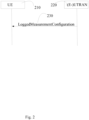
- Fig. 2 shows, by way of example, MDT measurement configuration for Logged MDT.
- the network e.g. (E-)UTRAN 220 in the example of Fig. 2 , may configure a UE 210 with Logged MDT measurement configuration using a LoggedMeasurementConfiguration message 230.
- a logged measurement configuration at a UE is released if it is replaced by another Logged MDT configuration or in case configuration clearance occurs, e.g. a duration timer expires or an expiration condition is met.
- the logged measurement configuration may be given as follows, as defined e.g. in TS 36.331:
- the logged measurements may comprise e.g.
- Logged measurement configurations and logs may be maintained when UE is in any state of a RAT even if there exist multiple periods of interruptions when UE is in a different RAT. There may be a single logged measurement configuration for Logged MDT in the UE for a RAT. When network provides a configuration, previously configured logged measurement configurations may be replaced by the new one. Logged measurements corresponding to previous configuration may be cleared also. In this case, network should be able to retrieve data before it is deleted, e.g., when a new configuration is given to the UE.
- Measurement logging is performed during logging intervals for which WLAN and Bluetooth measurements are available.
- measurement quantities for WLAN consist of service set identifier (SSID), basic SSID (BSSID), homogeneous extended SSID (HESSID) of WLAN access points (APs) and optionally received signal strength indicator (RSSI) and round-trip time (RTT).
- SSID service set identifier
- BSSID basic SSID
- HESSID homogeneous extended SSID
- RSSI received signal strength indicator
- RTT round-trip time
- measurement logging comprises MAC address of Bluetooth beacons and optionally available RSSI.
- UE may collect MDT measurements and logs according to its configuration until its memory reserved for MDT is full. If this happens, UE stops logging, stops the log duration timer and starts another timer, e.g. the 48 hour timer.
- a radio access network (RAN) optimization algorithm may comprise an algorithm for optimizing and/or improving operation, performance and/or one or more functions of a RAN.
- RAN optimization may comprise, for example, increasing or decreasing a priority of a service.
- RAN optimization, targeting end-user perception improvement comprises e.g. capacity and coverage optimization, load sharing, load balancing, random access channel (RACH) optimization and energy saving. These functions may be optimized by SON algorithms.
- a radio access network optimization algorithm may be implemented with, for example, a machine learning technology. The use of ML is applicable in SON solutions as well.
- Machine learning refers to algorithms and statistical models that computer systems use to perform a specific task without using explicit instructions, relying on patterns and inference instead. It is seen as a subset of artificial intelligence. Machine learning algorithms build a mathematical model based on sample data, known as "training data", in order to make predictions or decisions without being explicitly programmed to perform the task. ML algorithms may be categorized e.g. into supervised, unsupervised, and reinforcement learning. An ML algorithm may be composed of one or several ML components forming a, so called, ML pipeline, where each component may be placed and executed in different RAN network functions and/or in the UE itself.
- CU central unit
- CU-UP centralized unit control plane
- CU-UP centralized unit user plane
- DU decentralized unit
- a network node e.g. gNB
- RIC radio intelligent controller
- C-plane control plane
- Near real-time here may be understood e.g. as in the order of hundreds of milliseconds.
- the tailored MDT data may be received from data producers, e.g. from one or more UEs and/or one or more RAN network functions.
- the data producer may be a UE or a set of UEs that performs the measurements or an entity that requests one or more UEs to perform the measurements.
- the data producer sends the measurement results as a response to the consumer.
- the tailored data may be used by the consumer network function for executing and training the ML algorithm(s).
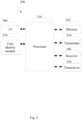
- Fig. 3 shows, by way of an example, a block diagram of an apparatus 300. Illustrated is an apparatus or device 300, which may comprise, for example, a network node, or a mobile communication device such as a user device or user equipment UE, or the entity where the ML algorithm is placed, or an entity triggered by the entity hosting the ML.
- processor 310 which may comprise, for example, a single- or multi-core processor wherein a single-core processor comprises one processing core and a multi-core processor comprises more than one processing core.
- Processor 310 may comprise, in general, a control device.
- Processor 310 may comprise more than one processor.
- Processor 310 may be a control device.
- a processing core may comprise, for example, a Cortex-A8 processing core manufactured by ARM Holdings or a Steamroller processing core designed by Advanced Micro Devices Corporation.
- Processor 310 may comprise at least one Qualcomm Snapdragon and/or Intel Atom processor.
- Processor 310 may comprise at least one application-specific integrated circuit, ASIC.
- Processor 310 may comprise at least one field-programmable gate array, FPGA.
- Processor 310 may be means for performing method steps in device 300.
- Processor 310 may be configured, at least in part by computer instructions, to perform actions, e.g. the method(s) as disclosed herein.
- a processor may comprise circuitry, or be constituted as circuitry or circuitries, the circuitry or circuitries being configured to perform phases of methods in accordance with embodiments described herein.
- circuitry may refer to one or more or all of the following: (a) hardware-only circuit implementations, such as implementations in only analog and/or digital circuitry, and (b) combinations of hardware circuits and software, such as, as applicable: (i) a combination of analog and/or digital hardware circuit(s) with software/firmware and (ii) any portions of hardware processor(s) with software (including digital signal processor(s)), software, and memory(ies) that work together to cause an apparatus, such as a mobile phone or server, to perform various functions) and (c) hardware circuit(s) and or processor(s), such as a microprocessor(s) or a portion of a microprocessor(s), that requires software (e.g., firmware) for operation, but the software may not be present when it is not needed for operation.
- firmware firmware
- circuitry also covers an implementation of merely a hardware circuit or processor (or multiple processors) or portion of a hardware circuit or processor and its (or their) accompanying software and/or firmware.
- circuitry also covers, for example and if applicable to the particular claim element, a baseband integrated circuit or processor integrated circuit for a mobile device or a similar integrated circuit in server, a cellular network device, or other computing or network device.
- Device 300 may comprise memory 320.
- Memory 320 may comprise random-access memory and/or permanent memory.
- Memory 320 may comprise at least one RAM chip.
- Memory 320 may comprise solid-state, magnetic, optical and/or holographic memory, for example.
- Memory 320 may be at least in part accessible to processor 310.
- Memory 320 may be at least in part comprised in processor 310.
- Memory 320 may be means for storing information.
- Memory 320 may comprise computer instructions that processor 310 is configured to execute. When computer instructions configured to cause processor 310 to perform certain actions are stored in memory 320, and device 300 overall is configured to run under the direction of processor 310 using computer instructions from memory 320, processor 310 and/or its at least one processing core may be considered to be configured to perform said certain actions.
- Memory 320 may be at least in part comprised in processor 310.
- Memory 320 may be at least in part external to device 300 but accessible to device 300.
- Device 300 may comprise a transmitter 330.
- Device 300 may comprise a receiver 340.
- Transmitter 330 and receiver 340 may be configured to transmit and receive, respectively, information in accordance with at least one cellular or non-cellular standard.
- Transmitter 330 may comprise more than one transmitter.
- Receiver 340 may comprise more than one receiver.
- Transmitter 330 and/or receiver 340 may be configured to operate in accordance with a mobile communication system standard, such as 5G, long term evolution, LTE, wireless local area network, WLAN and/or Ethernet.
- Device 300 may comprise a near-field communication, NFC, transceiver 350.
- NFC transceiver 350 may support at least one NFC technology, such as NFC, Bluetooth, Wibree or similar technologies.
- Device 300 may comprise user interface, UI, 360.
- UI 360 may comprise at least one of a display, a keyboard, a touchscreen, a vibrator arranged to signal to a user by causing device 300 to vibrate, a speaker and a microphone.
- a user may be able to operate device 300 via UI 360, for example to accept incoming telephone calls, to originate telephone calls or video calls, to browse the Internet, to manage digital files stored in memory 320 or on a cloud accessible via transmitter 330 and receiver 340, or via NFC transceiver 350, and/or to play games.
- Device 300 may comprise or be arranged to accept a user identity module 370.
- User identity module 370 may comprise, for example, a subscriber identity module, SIM, card installable in device 300.
- a user identity module 370 may comprise information identifying a subscription of a user of device 300.
- a user identity module 370 may comprise cryptographic information usable to verify the identity of a user of device 300 and/or to facilitate encryption of communicated information and billing of the user of device 300 for communication effected via device 300.
- Processor 310 may be furnished with a transmitter arranged to output information from processor 310, via electrical leads internal to device 300, to other devices comprised in device 300.
- a transmitter may comprise a serial bus transmitter arranged to, for example, output information via at least one electrical lead to memory 320 for storage therein.
- the transmitter may comprise a parallel bus transmitter.
- processor 310 may comprise a receiver arranged to receive information in processor 310, via electrical leads internal to device 300, from other devices comprised in device 300.
- Such a receiver may comprise a serial bus receiver arranged to, for example, receive information via at least one electrical lead from receiver 340 for processing in processor 310.
- the receiver may comprise a parallel bus receiver.
- Device 300 may comprise further devices not illustrated in Fig. 3 .
- device 300 may comprise at least one digital camera.
- Some devices 300 may comprise a back-facing camera and a front-facing camera, wherein the back-facing camera may be intended for digital photography and the front-facing camera for video telephony.
- Device 300 may comprise a fingerprint sensor arranged to authenticate, at least in part, a user of device 300.
- device 300 lacks at least one device described above.
- some devices 300 may lack a NFC transceiver 350 and/or user identity module 370.
- Processor 310, memory 320, transmitter 330, receiver 340, NFC transceiver 350, UI 360 and/or user identity module 370 may be interconnected by electrical leads internal to device 300 in a multitude of different ways.
- each of the aforementioned devices may be separately connected to a master bus internal to device 300, to allow for the devices to exchange information.
- this is only one example and depending on the embodiment various ways of interconnecting at least two of the aforementioned devices may be selected.
- Fig. 4 shows, by way of example, a set of different ML optimization problems 411, 412, 413, 414 within a consumer, e.g. an ML entity 420, and a producer entity 430.
- ML entity 420 may be considered as an entity that solves a set of k ML optimization problems, e.g. Problem 1 411, Problem 2 412, Problem 3 413... and Problem k 414.
- the ML optimization problems may correspond to some SON use cases, e.g. random access channel (RACH) optimization, mobility robustness optimization (MRO) and/or coverage capacity optimization (CCO) for example but could be more general and involve newly defined problems identified as part of lower or higher layer operations.
- RACH random access channel
- MRO mobility robustness optimization
- CO coverage capacity optimization
- the ML entity 420 may be e.g. a UE or a RAN network function or may be a network function that resides outside RAN.
- the ML algorithm(s) are executed with needed measurements provided from a UE or another network function that own the needed measurements.
- the ML may be deployed in different entities, i.e. the network function that requests the measurements may be e.g. CU, DU, both CU and DU, a network node, e.g. gNB, RIC, etc.
- the ML algorithm may reside on a single network entity or may be distributed in multiple network entities.
- the data producer 430 then depends on the place where the ML is deployed and the location of the data needed for the ML algorithm. Location of the needed data may depend on the type of the measurements, as some measurements are associated with higher layers and others with lower layers.
- the data producer may be e.g. one or more UEs or an entity that requests one or more UEs to perform measurements.
- O-RAN open RAN
- the data producer may be e.g. the radio intelligent controller (RIC).
- the ML entity 420 may request 440 the set of measurements from the data producer 430.
- the measurement request may be the message "Request Filter Set”.
- Filter sets may be specified, which comprise a set of quadruplets of ⁇ "UE identity"; “UE measurements”; “Time sampling indication”; “Granularity” ⁇ that allows a given entity, e.g. the data producer 430, to request specific measurements for one or more UEs.
- the quadruplets of measurement data become triplets, i.e. ⁇ "UE measurements”; “Time sampling indication”; “Granularity” ⁇ .
- the data producer 430 may act according to request, and transmit 450 a response message, e.g. "Response Filter Set" to the ML entity 420.
- a response message e.g. "Response Filter Set”
- the existing UE Information Request/Response messages may be reused, wherein the filter set information is passed or transmitted as an information element.
- the ML entity 420 may identify and/or select the set of UEs from which to request data. Those UEs may be identified e.g. through specific UE Identities. Alternatively, or in addition, those UEs may be identified and/or selected which satisfy certain pre-defined conditions: e.g., "UEs whose throughput is below a threshold", “UEs whose reference signal received power (RSRP) values are below a certain threshold”, “UEs whose reference signal received quality (RSRQ) values are within a certain window”, “UEs whose handover failed more than a certain number of times in a certain area”, etc.
- RSRP reference signal received power
- RSSQ reference signal received quality
- a measurement may be mobility state estimation (MSE)/location, radio link failure (RLF)/beam, random access channel (RACH) contention resolution failure/resource/beam, #RACH preambles/resource/beam, Reference Signals Received Power (RSRP), Signal to Interference plus Noise Ratio (SINR) or other physical layer measurements, etc.
- MSE mobility state estimation
- RLF radio link failure
- RACH random access channel
- RSRP Reference Signals Received Power
- SINR Signal to Interference plus Noise Ratio
- the measurement M(j) may be associated with a time sampling indication.
- the time sampling indication may give information regarding the starting time when the measurement will be collected, the ending time and the time frequency of the sampling. Time frequency of the sampling may indicate how often and with which pattern between the starting and ending times data will be collected.
- the time sampling indication may comprise the necessary time units of those times, e.g. seconds, milliseconds, hours, days, etc.
- the starting time, ending time and/or the frequency of the sampling may be event-based. This means that the measurements may be collected when a certain event is satisfied. The measurements may be collected e.g. in a non-deterministic and aperiodic fashion. Example of such events can be nonfailure related conditions, e.g.: "RSRP drops below a threshold”, “handover failure” (e.g., on a certain beam index or location or combination of the above), “RACH failure on given resources” (in terms of frequency, time, beam index, preamble or a combination of those parameters).
- time sampling indication A few, non-limiting, examples of time sampling indication are given below.
- Time sampling indication may be defined with a fixed period with which measurements are collected.
- the start and/or end times of the measurement collection period and/or the period itself may be indicated in the time sampling indication (together with their respective units, e.g., minutes, seconds, hours, days, etc.).
- the start time may be event-based, i.e. the entity may start taking measurements once an event is observed.
- the end time may be also event-based, i.e., the entity may finish taking of measurements when another event is observed.
- the time sampling indication is defined as event-based measurement collection
- the measurements are collected when a certain event is observed.
- the starting and/or ending times may be time-based or event-based times.
- Time sampling indication may be defined with a schedule that gives a pattern with which to collect the measurements.
- the schedule comprises start times and end times of the measurement periods.
- Such time sampling indication can be useful in cases for example of deterministic traffic as being discussed for Ultra Reliable Low Latency Communications (URLLC).
- URLLC Ultra Reliable Low Latency Communications
- some events e.g., transmission collisions, interference, throughput updates, etc.
- deterministic or semi-deterministic mobility for factory automation applications would create events that follow a deterministic pattern, e.g., when it comes to handover failures.
- the start times and end times may be determined as event-based.
- the units of the starting and ending times and the schedule may also be indicated.
- the measurement M(j) may be associated with a granularity with which it will be collected. For example, if a measurement is tied to a location, e.g. observing a certain quantity/location, the location may be a point (x,y,z) or it may be a larger location, such as a cell edge or a coverage hole. If the measurement is tied to a beam, e.g. observing a certain quantity/beam, its granularity may be an index of the beam or a grid of beams.
- Fig. 5 shows, by way of example, a filter set representation 500.
- the UEs from which measurements are requested are assumed to be pre-selected.
- the fourth dimension, the UE Identities, or the set of UE-Id(s) that need to collect the measurements is not shown, and the message comprising the filter sets is represented in three dimensions, i.e., x, y and z. Effectively, the message in Fig. 5 is the message that will be received by a given (pre-selected) UE.
- the filter set may be a 4-dimensional matrix, pointing to a set of specific identified UEs (or UE satisfying certain events) from which measurements are requested, or 3-dimensional in which the selection of the UEs has already taken place.
- the number of dimensions of the filter set depends on the recipient, namely if it is a UE or another network function. If the filter set message is sent to a CU, for example, then the CU may indicate from which UEs it requests the measurements.
- the x dimension 510 represents measurements, e.g. all possible measurements, e.g. M(1), M(2), M(3), M(4), M(5)...M(m).
- the y dimension 520 represents the possible time sampling indications, e.g. T(1), T(2), T(3), T(4)....
- the z dimension 530 represents the granularity, e.g. G(1), G(2), G(3), G(4)....
- the (x,y,z) components that are black, i.e. the components 541, 542, 543, 544 in the matrix in Fig. 5 represent the filtered measurements that are requested by an entity (by a data consumer). The entity receiving the message (data producer) will send the filtered measurements to the data consumer.
- the black components represent with which sampling and granularity these measurements are needed.
- the black components in Fig. 5 correspond to a tailored set of measurements, which may be named as a filter set.
- the filter set may be created by taking one or more subset over all relevant measurements.
- All the measurements may be indicated to all the UEs (UEs, set of UEs or UE Types) or other network entities (CU, DU, gNB, RIC, etc.), even if all of those do not collect all the measurements.
- UEs UEs, set of UEs or UE Types
- CU DU, gNB, RIC, etc.
- only relevant entries of the matrix may be communicated.
- an array or vector of measurements IDs to be activated or deactivated may be indicated in a configuration message towards the entity, from which the measurements are requested, by the entity gathering the measurements.
- This kind of dynamic implementation enables reduction of the matrix size by avoiding unnecessary elements.
- Communication of the relevant entries of the matrix may be carried out by the configuration message, e.g. Configure Filter Set Message.
- a filter set pertains to a particular ML optimization problem 1,2,...,k, where the problem corresponds to a certain use case in the network, targeting an issue and an optimization need.
- the optimization need may be, for example, coverage and capacity optimization (CCO), Mobility Robustness Optimization (MRO), QoS verification, RACH Optimization, Common Channel Parameterization (CCP), etc.
- Measurement filters corresponding to filters in the x dimension of Fig. 5 , may be e.g.
- This kind of definition of the filter sets enables defining new ML optimization problems. It further allows defining own filter sets mapped to a given optimization problem in a proprietary way.
- the ML entity in need of certain measurement(s), may configure filter sets for a certain ML optimization problem k' at the data producer or directly at a UE.
- a single filter set may be mapped to a given ML optimization problem.
- multiple filter sets may be mapped to a single optimization problem. For example, for an ML optimization problem where both immediate and logged MDT measurements are required, multiple filter sets may be mapped to a single optimization problem.
- the ML optimization problem may be signaled explicitly in the configuration message and/or in the request/response messages for the filter set.
- the ML entity may request "measurements to solve optimization problem k' " and also request certain filter sets, e.g. a subset of the configured ones.
- the entity requesting the measurements indicates also the purpose of the measurements, in addition to which measurements it requests.
- the configuration and/or the request/response procedures are explicitly tied to a particular ML optimization problem, and it is indicated to the entity from which measurement are requested, e.g. the data producer, additional intelligence is added to the entity from which measurement are requested.
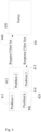
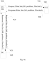
- Fig. 6a shows, by way of example, signaling between ML entity 610 and a data producer 620.
- the ML entity 610 configures 630 filter sets for a certain ML optimization problem k' at the data producer 620.
- Measurement configurations and requests to a data producer are tied to a specific ML optimization problem which is indicated to the data producer.
- the data producer may start performing the measurements and/or collecting the measurements from one or more UEs.
- the data producer 620 transmits 632 a message on data availability regarding the specific problem k' to the ML entity 610.
- the message on data availability may indicate that the data producer has collected the requested data for a particular problem. It may be that data becomes available at different points of time for different optimization problems.
- the data producer may transmit multiple messages on data availability regarding different optimization problems to the ML entity.
- ML entity transmits 634 the measurement request "Request Filter Set" to the data producer 620.
- Filter sets may specify the set of the UEs from which measurements are requested by indicating the identity of UEs from which measurement should be collected in the measurement request, i.e. the filter set is four dimensional.
- the ML optimization problem is given as an argument of the request and specific measurements are mapped to a certain optimization problem.
- the data producer acts according to the request, and then transmits 636 a message "Response Filter Set" to the ML entity.
- the ML entity receives the message "Response Filter Set” from the data producer.
- the existing UE Information Request/Response messages may be reused, wherein the filter set information is passed or transmitted as an information element.
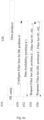
- Fig. 6b shows, by way of example, signaling between ML entity 660 and UE 670.
- the data producer is the UE.
- the ML entity 660 configures 680 filter sets for a certain ML optimization problem k' at the UE 670. Measurement configurations and requests to the UE are tied to a specific ML optimization problem which is indicated to the UE.
- the UE 670 transmits 682 a message on data availability regarding the specific problem k' to the ML entity 660.
- ML entity 660 transmits 684 the measurement request "Request Filter Set" to the UE 670.
- the filter set is three dimensional, i.e. the UE information is already interpreted by configuring and requesting measurements from specific UEs.
- the ML optimization problem is given as an argument of the request and specific measurements are mapped to a certain optimization problem.
- Different Filter Sets are denoted as #f1, #f2....
- the UE acts according to the request, and then transmits 686 a message "Response Filter Set” to the ML entity.
- the ML entity receives the message "Response Filter Set” from the UE.
- the UE that receives a request for specific filter sets and takes the measurements may store the measurements to its local memory until it obtains all the needed information. When all the needed measurements have been taken, the UE sends the measurements back to the data producer or to the ML entity. It may be that the data is not processed at the UE in order to reduce volume or UE may additionally process the data.
- the procedures in Fig. 6a and in Fig. 6b will yield in the response filter set message a matrix of the form in Fig. 5 .
- the UEs from which measurements are obtained may be appended in the response. Those UEs may be a subset of the UEs from which measurements are requested or all the UEs indicated in the request filter set message. For instance, if the measurements are measuring average throughput over a set of UEs and if not all UEs report throughput measurements, the requesting entity should be aware of which UEs provided measurements.
- the UE indication is omitted, i.e., the 4-dimensional matrix becomes 3-dimensional.
- configuration may be done by introducing a new configuration message or by reusing the LoggedMeasurementConfiguration message to include the filter sets.
- the configuration message may also indicate the ML optimization problem for which the measurements are requested which gives an indication that data is requested for ML purposes.
- the entity sending the configuration message may alternatively be an entity triggered by the entity hosting the ML.
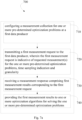
- Fig. 7a shows, by way of example, a flow chart of a method for RAN data collection.
- the phases of the method 700 may be performed e.g. by the device 300, e.g. the ML entity, or an entity triggered by the entity hosting the ML.
- the method 700 comprises configuring 710 a measurement collection for one or more pre-determined optimization problems at a first data producer.
- the method 700 comprises transmitting 720 a first measurement request to the first data producer, wherein the first measurement request is indicative of requested measurement(s) for the one or more pre-determined optimization problems, time sampling indication and granularity.
- the method 700 comprises receiving 730 a measurement response comprising first measurement results corresponding to the first measurement request.
- the method 700 comprises providing 740 the first measurement results to one or more optimization algorithms for solving the one or more pre-determined optimization problems.
- Fig. 7b shows, by way of example, a flow chart of a method for RAN data collection.
- the phases of the method 750 may be performed e.g. by the device 300, e.g. the data producer such as an UE or an entity that requests one or more UEs to perform the requested measurements.
- the method 750 comprises receiving 760 a configuration of a measurement collection for one or more pre-determined optimization problems.
- the configuration may be received e.g. from the ML entity.
- the method 750 comprises receiving 770 a first measurement request indicative of requested measurement(s) for the one or more pre-determined optimization problems, time sampling indication and granularity.
- the method 750 comprises performing 780 the requested measurement(s) according to the first measurement request and/or requesting the requested measurement(s) according to the first measurement request from one or more user equipments.
- the method 750 comprises transmitting 790 a measurement response comprising first measurement results corresponding to the first measurement request.
- the measurement response may be transmitted e.g. to the ML entity.
- the method wherein a tailored measurement request is used, enables collecting and reporting the data in an efficient way, which helps the UEs to better utilize their resources, such as memory and battery.
- the network may process received measurements faster and use less storage and processing resources.
- the methods may be applied to both Immediate MDT and Logged MDT.
- Measurement requests and/or measurement responses may be sent over different interfaces depending on the location where the ML entity is placed.
- the signalling for MDT data collection may be over F1/E1 interface; over X2/Xn interface between gNBs or eNBs; over E2 and/or A1 interfaces in O-RAN.
- the overall set of measurements may be split into two different parts, namely measurements that are collected from a CU and measurements that are collected from a DU. Measurements may be collected from a first data producer and from a second data producer.
- Fig. 8 shows, by way of example, signalling between entities, wherein the ML is placed in a RAN external entity.
- the RAN external entity may be e.g. the RIC in O-RAN or TCE in the OAM domain.
- the ML entity 810 may transmit 820 a measurement request to CU 812, and receive 825 a measurement response from the CU 812.
- the ML entity 810 may trigger a Request Filter Set procedure 820 and a Response Filter Set procedure 825 over the ML-CU 812 interface.
- the set of measurements triggered by the CU may be named as a first set of measurements, i.e. filterSet1.
- the set of measurements triggered by the DU may be named as a second set of measurements, i.e. filterSet2.
- the ML entity may transmit 830 a measurement request to DU 814, and receive 835 a measurement response from the DU 814.
- the ML entity 810 may trigger a Request Filter Set procedure 830 and a Response Filter Set procedure 835 over the ML-DU 814 interface.
- the ML entity may indicate the pre-determined ML problem for which measurement results are needed.
- a set of UEs from which measurements should be obtained may be indicated in the measurement request message. For example, those UEs could be UEs satisfying a certain condition or UEs identified through certain identifiers.
- CU 812 and DU 814 When CU 812 and DU 814 receive the Requests for Filter Sets from the ML entity, and if those Filter Sets involve measurements from UEs, they subsequently send the corresponding measurement configuration messages at the UEs for the requested ML Problems and Filter Sets. From this process filterSet1 and filterSet2 are obtained. Measurements that are to be collected from the CU or from the DU are different since naturally the two entities handle different types of information. The CU deals with higher layer information as opposed to the DU which handles more physical layer information. The ML entity that receives both filterSet1 and filterSet2 can use them to optimize its ML optimization problems.
- Fig. 9a shows, by way of example, signalling between entities, wherein the ML is placed at the CU 910.
- the ML at the CU 910 i.e. the ML entity in this example, may transmit 920 a measurement request to DU 912, and receive 925 a measurement response from the DU 912.
- the ML at the CU may trigger a Request Filter Set procedure 920 and a Response Filter Set procedure 925 over the F1 interface with the DU 912, or through some newly defined interface that could interconnect ML entities between CU and DUs.
- the ML at the CU may obtain, from these procedures, a set of measurements given by filterSet2.
- a set of UEs from which measurements should be obtained may be indicated in the measurement request message. For example, those UEs could be UEs satisfying a certain condition or UEs identified through certain identifiers.
- the pre-determined ML problem for which measurement results are needed may be indicated in the measurement request.
- the ML at the CU may transmit 930 a measurement request to one or more UEs 940, and receive 935 a measurement response from the one or more UEs 940.
- the ML at the CU may trigger measurement collection from specific UEs by sending Request Filter Set to certain UEs and receiving Response Filter Set from the UEs.
- UE information may exist as part of the source and/or destination of the Request Filter Set.
- no UE indication is included in the Request Filter Set message.
- ML may obtain a set of measurements given by filterSet1. Having both filterSet1 and filterSet2 the ML at the CU may use the measurement results given by the filterSet1 and filterSet2 to optimize certain ML optimization problems.
- Fig. 9a it may be assumed that the UEs 940 are already configured to collect the measurements for a given ML problem and filter set.
- Fig. 9b shows, by way of example, signalling between entities, wherein the ML is placed at the CU-CP 950.
- the ML at the at the CU-CP i.e. the ML entity in this example, may transmit 970 a measurement request to DU 960, and receive 975 a measurement response from the DU 960.
- the ML at the CU-CP may trigger a Request Filter Set procedure 970 and a Response Filter Set procedure 975 over the F1 interface or through some newly defined interface that could interconnect ML entities between CU and DUs.
- the ML at the CU-CP may obtain, from these procedures, a set of measurements given by filterSet2.
- a set of UEs from which measurements should be obtained may be indicated in the measurement request message. For example, those UEs could be UEs satisfying a certain condition or UEs identified through certain identifiers.
- the pre-determined ML problem for which measurement results are needed may be indicated in the measurement request.
- the ML at the CU-CP 950 may transmit 990 a measurement request to CU-UP 980, and receive 995 a measurement response from the CU-UP 980.
- the ML at the CU-UP may trigger a Request Filter Set procedure 990 and a Response Filter Set procedure 995 over the E1 interface or through some newly defined interface that could interconnect ML entities between CU-CP and CU-UP.
- the ML at the CU-CP may obtain, from these procedures, a set of measurements given by filterSet4. Having both filterSet2 and filterSet4 the ML at the CU-CP may use the measurement results given by the filterSet2 and filterSet4 to optimize certain ML optimization problems, which may be different from each other.
- Fig. 9b it may be assumed that the UEs are already configured to collect the measurements for a given ML problem and filter set.
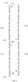
- Fig. 10 shows, by way of example, signalling between entities, wherein the ML is placed at the DU 1010.
- the ML at the DU 1010 i.e. the ML entity in this example, may transmit 1020 a measurement request to CU 1012, and receive 1025 a measurement response from the CU 1012.
- the ML at the DU may trigger a Request Filter Set procedure 1020 and a Response Filter Set procedure 1025 over the F1 interface with the CU 1012 or through some newly defined interface that could interconnect ML entities between CU and DUs.
- the ML at the DU may obtain, from these procedures, a set of measurements given by filterSet1.
- a set of UEs from which measurements should be obtained may be indicated in the measurement request message. For example, those UEs could be UEs satisfying a certain condition or UEs identified through certain identifiers.
- the pre-determined ML problem for which measurement results are needed may be indicated in the measurement request.
- the ML at the DU may transmit 1030 a measurement request to one or more UEs 1040, and receive 1035 a measurement response from the one or more UEs 1040.
- the ML at the DU may trigger measurement collection from specific UEs by sending Request Filter Set to certain UEs and receiving Response Filter Set from the UEs.
- UE information may exist as part of the source and/or destination of the Request Filter Set.
- no UE indication is included in the Request Filter Set message.
- the ML may obtain a set of measurements given by filterSet2 from this process. Having both filterSet1 and filterSet2 the ML at the DU may use the measurement results given by the filterSet1 and filterSet2 to optimize certain ML optimization problems.
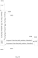
- Fig. 11 shows, by way of example, signalling between entities, wherein the ML is placed at a network node 1110, e.g. at the gNB.
- the ML may exist as an entity within the gNB, which does not support the fronthaul functional CU-DU split.
- the ML in the gNB 1110 i.e. the ML entity in this example, may transmit 1120 a measurement request to one or more UEs 1130, and receive 1125 a measurement response from the one or more UEs 1130.
- the ML at the gNB 1110 may trigger a Request Filter Set procedure 1120 and a Response Filter Set procedure 1125 directly from a set of UEs.
- the UEs may be identified through UE identifiers or they may be UEs satisfying a certain condition.
- the ML may obtain a set of measurements given by filterSetl and filterSet2, which may be used by the ML to optimize certain ML optimization problems. In the example of Fig. 11 , it may be assumed that the UEs are already configured to collect the measurements for a given ML problem and filter set.
- ML pipeline may comprise multiple components which may be located in different entities.
- Fig. 12 shows, by way of example, signalling between entities, wherein the ML is distributed with parts of it placed both at the CU 1210 and the DU 1240.
- Fig. 13 shows signalling between entities, wherein the ML algorithm is partly located in one network node, e.g. gNB 1310, and partly in another network node, e.g. gNB 1320.
- the ML at the CU 1210 may trigger measurement collection from particular UEs by sending 1220 Request Filter Set to one or more UEs 1230 and receiving 1225 a Response Filter Set from the one or more UEs 1230.
- no UE indication is included in the Request Filter Set message.
- the ML may obtain a set of measurements given by filterSet1 from this process.
- the ML at the DU 1240 may trigger measurement collection from particular UEs by sending 1250 Request Filter Set to one or more UEs 1260 and receiving 1255 a Response Filter Set from the one or more UEs 1260.
- no UE indication is included in the Request Filter Set message.
- the ML may obtain a set of measurements given by filterSet2 from this process.
- the one or more UEs 1230 and one or more UEs 1260 may be the same set of UEs, at least partly, i.e. they may have some overlaps.
- a filterSet3 may need to be communicated 1270 between CU and DU in this case which could correspond to measurements that the ML entity at one, e.g., CU(/DU) needs to request from the other, e.g., DU/CU.
- UEs are already configured to collect the measurements for a given ML problem and filter set.
- the ML is placed at two different gNBs, e.g. a first network node 1310 and a second network node 1320. It is to be noted, however, that the ML may be placed at more than two different network nodes.
- the filter sets need to be communicated across the X2 interface or Xn interface or through some newly defined interface that could interconnect ML entities between eNBs or gNBs respectively 1315.
- Request Filter Set message may be transmitted 1330 from the first network node 1310 to the second network node 1320, and Response Filter Set message may be transmitted 1335 from the second network node 1320 to the first network node 1310.
- Fig. 14 shows, by way of example, signalling in coverage and capacity optimization (CCO).
- the ML entity 1410 may configure 1440, 1442 a set of UEs, e.g. a first UE 1420 and a second UE 1430 with measurements for CCO optimization.
- the first UE may be the first data producer.
- the second UE may be the second data producer.
- CCO optimization is the given ML optimization problem in this example.
- the measurements with which the UEs are configured may be related to radio measurements and/or detailed location information.
- the ML may receive 1444, 1446 indications of data availability for the CCO.
- the ML entity 1410 may request 1450, 1452 different subsets of the available measurements from different UEs.
- Measurement Filter x is comprised in the Request Filter Set sent to the first UE 1420.
- Measurement Filter x may comprise e.g. serving cell signal and global positioning system (GPS) information.
- Measurement Filter y is comprised in the Request Filter Set sent to the second UE 1430.
- Measurement Filter y may comprise, e.g. neighboring cells signal.
- the UEs may transmit 1460, 1462 a measurement response, i.e. Response Filter Set to the ML entity.
- the Response Filter Set from the first UE 1420 comprises e.g. RSRP/RSRQ/SINR/GNSS, time sampling indication and granularity.
- the Response Filter Set from the second UE 1430 comprises e.g. RSRP/RSRQ/SINR, time sampling indication' and granularity'.
- the filter sets are 3-dimensional, i.e. the selection of the UEs has already taken place.
- Fig. 15 shows, by way of example, signalling between entities, wherein termination conditions for ML algorithm(s) are evaluated.
- a network node 1510 e.g. a gNB, hosting the ML algorithm may configure 1520, 1522 Filter Sets corresponding to different ML optimization problems at the UEs, e.g. UE1 1512 and UEn 1514.
- the gNB may request 1524, 1526 Filter Set measurements for different ML optimization problems.
- Filter Set x is requested from UE1 1512.
- Filter Set y is requested from UEn 1514.
- ML algorithms may compute a cost or reward which may determine how well the ML algorithm performs, i.e. does the ML algorithm show required convergence or not.
- a model training termination validation procedure 1534 may be performed which determines whether the ML algorithm has reached the desired performance.
- the cost or reward that is calculated may be compared 1536 to pre-determined optimal cost or reward, denoted as Cost Optx and Cost Opty in Fig. 15 , Fig. 16 and Fig. 17 .
- the algorithm for each ML optimization problem may terminate if the two costs or rewards are close enough.
- the costs or rewards may be e.g. compared against a ML problem-dependent threshold, denoted as epsilon x and epsilon_y in Fig. 15 , Fig. 16 and Fig. 17 .
- a ML problem-dependent threshold denoted as epsilon x and epsilon_y in Fig. 15 , Fig. 16 and Fig. 17 .
- This helps the gNB hosting the ML to save resources, such as energy, memory, etc. If the cost or reward is farther from the optimal cost or reward, more measurements may be requested, and the ML optimization problems may be retrained.
- the cost or reward procedure is just an example to explain the need for requesting more information or switch off measurements report.
- Fig. 15 shows one scenario 1540 of evaluation of termination conditions for ML algorithm. Based on comparison 1542 to pre-determined optimal cost or reward and against a ML problem-dependent threshold, it is detected 1544 that both ML optimization problem x and ML optimization problem y need more measurements.
- the gNB may request 1546, 1548 more measurements from the UEs for both ML optimization problems.
- ML may request different filters, e.g. Filter Set x' and Filter Set y', from different UEs corresponding to different subsets of the measurements, different granularities and different time sampling indications.
- the filter sets requested for each ML optimization problem may depend on the performance of the ML algorithm and whether it needs an increase or decrease in the measurements. For instance, it may request data from higher or lower number of UEs, and/or data to be sampled with a higher or smaller periodicity, and/or larger or smaller granularity, etc. If the performance is below a pre-determined threshold, the further measurement request is indicative of more requested measurements than in the first measurement request, and/or time sampling indication that indicates higher frequency of measurement sampling than in the first measurement request, and/or higher granularity than in the first measurement request.
- the further measurement request is indicative of less requested measurements than in the first measurement request, and/or indicative of requesting data from lower number of UEs than in the first measurement request, and/or time sampling indication that indicates lower frequency of measurement sampling than in the first measurement request, and/or lower granularity than in the first measurement request.
- the gNB 1510 can use them for retraining 1554 its ML optimization algorithms.
- ML algorithms may compute a cost or reward which may determine how well the ML algorithm performs.
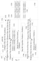
- Fig. 16 shows another scenario 1640 of evaluation of termination conditions for ML algorithm, wherein the algorithm for problem x may be terminated while algorithms for problem y needs to obtain more measurements.
- the algorithm for problem x may be terminated while algorithms for problem y needs to obtain more measurements.
- ML optimization algorithm for problem x may be stopped.
- measurements e.g. light measurements, e.g. Filter Set x
- measurements may be requested 1646 by the ML in the gNB in order to monitor network performance.
- the gNB may request 1648 more measurements, e.g.
- Filter Set y' e.g. from higher number of UEs, and/or of higher granularity and/or more frequent time sampling indications.
- the gNB 1510 may monitor 1654 performance based on the received measurements relating to problem x, and retrain 1654 its ML optimization algorithms relating to problem y.
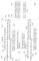
- Fig. 17 shows still another scenario 1740 of evaluation of termination conditions for ML algorithm, wherein the algorithms for problems x and y may be stopped. Based on comparison 1742 to pre-determined optimal cost or reward and against a ML problem-dependent threshold, it is detected 1744 that Both ML optimization problem x and ML optimization problem y have satisfactory performance and meet the termination condition. So, the gNB may switch off 1744 both ML optimization algorithms. However, the gNB may still request 1746, 1748 some measurements, e.g. light measurements, e.g. Filter Set x" and Filter Set y", to monitor network performance. After receiving 1750, 1752 the new filter sets, the gNB 1510 may monitor 1754 performance based on the received measurements relating to problem x and problem y.
- some measurements e.g. light measurements, e.g. Filter Set x" and Filter Set y
Landscapes
- Engineering & Computer Science (AREA)
- Computer Networks & Wireless Communication (AREA)
- Signal Processing (AREA)
- Mobile Radio Communication Systems (AREA)
Claims (15)
- Vorrichtung, die einen oder mehrere Maschinenlernoptimierungsalgorithmen zum Lösen von einem oder mehreren vorbestimmten Optimierungsproblemen sowie Mittel für Folgendes umfasst:Auslegen (710) eines ersten Datenproduzenten zum Sammeln von Messungen zum Lösen des einen oder der mehreren vorbestimmten Optimierungsprobleme unter Verwendung des einen oder der mehreren Maschinenlernoptimierungsalgorithmen;Übertragen (720) einer ersten Messanforderung zum ersten Datenproduzenten, wobei die erste Messanforderung eine oder mehrere angeforderte Messungen für das eine oder die mehreren vorbestimmten Optimierungsprobleme, eine Zeitabtastungsanzeige und eine Granularität der einen oder der mehreren Messungen anzeigt;Empfangen (730) einer Messantwort, die erste Messergebnisse umfasst, die der ersten Messanforderung entsprechen, vom ersten Datenproduzenten;Lösen (740) des einen oder der mehreren vorbestimmten Optimierungsprobleme durch den einen oder die mehreren Maschinenlernoptimierungsalgorithmen unter Verwendung der Messantwort;Bestimmen einer Durchführung des einen oder der mehreren Maschinenlernoptimierungsalgorithmen; undÜbertragen einer weiteren Messanforderung zum ersten Datenproduzenten, wobei die weitere Messanforderung eine oder mehrere angeforderte Messungen für das eine oder die mehreren vorbestimmten Optimierungsprobleme anzeigt und auf Basis der bestimmten Leistung des einen oder der mehreren Maschinenlernoptimierungsalgorithmen bestimmt wird, dass sich die weitere Messanforderung mindestens teilweise von der ersten Messanforderung unterscheidet.
- Vorrichtung nach Anspruch 1, wobei die eine oder die mehreren angeforderten Messungen an einen Standort oder einen Strahl gebunden sind; und
die Granularität der einen oder der mehreren Messungen ist mit dem Standort oder dem Strahl verknüpft. - Vorrichtung nach einem der vorhergehenden Ansprüche, die ferner Mittel für Folgendes umfasst:
Empfangen einer Anzeige zu einer Datenverfügbarkeit mit Bezug auf das eine oder die mehreren vorbestimmten Optimierungsprobleme vom ersten Datenproduzenten. - Vorrichtung nach einem der vorhergehenden Ansprüche, wobei der erste Datenproduzent eine Teilnehmereinrichtung ist, von der Messungen angefordert werden.
- Vorrichtung nach einem der vorhergehenden Ansprüche, die ferner Mittel für Folgendes umfasst:Auslegen eines zweiten Datenproduzenten zum Sammeln von Messungen zum Lösen des einen oder der mehreren vorbestimmten Optimierungsprobleme unter Verwendung des einen oder der mehreren Maschinenlernoptimierungsalgorithmen;Übertragen einer zweiten Messanforderung zum zweiten Datenproduzenten, wobei die zweite Messanforderung eine oder mehrere angeforderte Messungen für das eine oder die mehreren vorbestimmten Optimierungsprobleme, eine Zeitabtastungsanzeige und eine Granularität der einen oder der mehreren Messungen anzeigt;Empfangen einer Messantwort, die zweite Messergebnisse umfasst, die der zweiten Messanforderung entsprechen, vom zweiten Datenproduzenten;Lösen des einen oder der mehreren vorbestimmten Maschinenlernoptimierungsprobleme durch den einen oder die mehreren Maschinenlernoptimierungsalgorithmen unter Verwendung der Messantwort, die die zweiten Messergebnisse umfasst.
- Vorrichtung nach Anspruch 5, wobei sich die zweite Messanforderung mindestens teilweise von der ersten Messanforderung unterscheidet.
- Vorrichtung nach einem der vorhergehenden Ansprüche, wobei die Mittel ferner dazu ausgelegt sind, Folgendes durchzuführen:
in Reaktion darauf, dass die bestimmte Leistung unter einem vorbestimmten Schwellwert liegt, Definieren der weiteren Messanforderung, die Folgendes anzeigen soll- mehr angeforderte Messungen als in der ersten Messanforderung; und/oder- eine Zeitabtastungsanzeige, die eine höhere Häufigkeit der Messwertabtastung anzeigt als in der ersten Messanforderung; und/oder- eine höhere Granularität als in der ersten Messanforderung. - Vorrichtung nach einem der vorhergehenden Ansprüche, wobei die Mittel ferner dazu ausgelegt sind, Folgendes durchzuführen:
in Reaktion darauf, dass die bestimmte Leistung über einem vorbestimmten Schwellwert liegt, Definieren der weiteren Messanforderung, die Folgendes anzeigen soll- weniger angeforderte Messungen als in der ersten Messanforderung; und/oder- Anfordern von Daten von einer geringeren Anzahl von UEs als in der ersten Messanforderung; und/oder- eine Zeitabtastungsanzeige, die eine geringere Häufigkeit der Messwertabtastung anzeigt als in der ersten Messanforderung; und/oder- eine geringere Granularität als in der ersten Messanforderung. - Vorrichtung, bei der es sich um einen ersten Datenproduzenten handelt und die Mittel für Folgendes umfasst:Empfangen (760) einer Auslegung einer Messwertsammlung zum Lösen von einem oder mehreren vorbestimmten Optimierungsproblemen unter Verwendung von einem oder mehreren Maschinenlernoptimierungsalgorithmen von einer Vorrichtung, die den einen oder die mehreren Maschinenlernoptimierungsalgorithmen zum Lösen des einen oder der mehreren vorbestimmten Optimierungsprobleme umfasst;Empfangen (770) einer ersten Messanforderung, die eine oder mehrere angeforderte Messungen für das eine oder die mehreren vorbestimmten Optimierungsprobleme, eine Zeitabtastungsanzeige und eine Granularität der einen oder der mehreren Messungen anzeigt, von der Vorrichtung;Durchführen (780) der einen oder der mehreren angeforderten Messungen gemäß der ersten Messanforderung und/oder Anfordern der einen oder der mehreren angeforderten Messungen gemäß der ersten Messanforderung von einer oder mehreren Teilnehmereinrichtungen;Übertragen (790) einer Messantwort, die erste Messergebnisse umfasst, die der ersten Messanforderung entsprechen, zur Vorrichtung; undEmpfangen einer weiteren Messanforderung von der Vorrichtung, wobei die weitere Messanforderung eine oder mehrere angeforderte Messungen für das eine oder die mehreren vorbestimmten Optimierungsprobleme anzeigt und sich die weitere Messanforderung in Abhängigkeit von einer Leistung des einen oder der mehreren Maschinenlernoptimierungsalgorithmen an der Vorrichtung mindestens teilweise von der ersten Messanforderung unterscheidet.
- Vorrichtung nach Anspruch 9, wobei die eine oder die mehreren angeforderten Messungen an einen Standort oder einen Strahl gebunden sind; und
die Granularität der einen oder der mehreren Messungen ist mit dem Standort oder dem Strahl verknüpft. - Verfahren, das Folgendes umfasstAuslegen (710) eines ersten Datenproduzenten zum Sammeln von Messungen zum Lösen von einem oder mehreren vorbestimmten Optimierungsproblemen unter Verwendung von einem oder mehreren Maschinenlernoptimierungsalgorithmen durch eine Vorrichtung, die den einen oder die mehreren Maschinenlernoptimierungsalgorithmen zum Lösen des einen oder der mehreren vorbestimmten Optimierungsprobleme umfasst;Übertragen (720) einer ersten Messanforderung durch die Vorrichtung zum ersten Datenproduzenten, wobei die erste Messanforderung eine oder mehrere angeforderte Messungen für das eine oder die mehreren vorbestimmten Optimierungsprobleme, eine Zeitabtastungsanzeige und eine Granularität der einen oder der mehreren Messungen anzeigt;Empfangen (730) einer Messantwort, die erste Messergebnisse umfasst, die der ersten Messanforderung entsprechen, durch die Vorrichtung vom ersten Datenproduzenten;Lösen (740) des einen oder der mehreren vorbestimmten Optimierungsprobleme durch den einen oder die mehreren Maschinenlernoptimierungsalgorithmen durch die Vorrichtung unter Verwendung der Messantwort;Bestimmen einer Durchführung des einen oder der mehreren Maschinenlernoptimierungsalgorithmen durch die Vorrichtung; undÜbertragen einer weiteren Messanforderung durch die Vorrichtung zum ersten Datenproduzenten, wobei die weitere Messanforderung eine oder mehrere angeforderte Messungen für das eine oder die mehreren vorbestimmten Optimierungsprobleme anzeigt und auf Basis der bestimmten Leistung des einen oder der mehreren Maschinenlernoptimierungsalgorithmen bestimmt wird, dass sich die weitere Messanforderung mindestens teilweise von der ersten Messanforderung unterscheidet.
- Verfahren, das Folgendes umfasst:Empfangen (760) einer Auslegung einer Messwertsammlung zum Lösen von einem oder mehreren vorbestimmten Optimierungsproblemen durch einen ersten Datenproduzenten unter Verwendung von einem oder mehreren Maschinenlernoptimierungsalgorithmen von einer Vorrichtung, die den einen oder die mehreren Maschinenlernoptimierungsalgorithmen zum Lösen des einen oder der mehreren vorbestimmten Optimierungsprobleme umfasst;Empfangen (770) einer ersten Messanforderung, die eine oder mehrere angeforderte Messungen für das eine oder die mehreren vorbestimmten Optimierungsprobleme, eine Zeitabtastungsanzeige und eine Granularität der einen oder der mehreren Messungen anzeigt, durch den ersten Datenproduzenten von der Vorrichtung;Durchführen (780) der einen oder der mehreren angeforderten Messungen durch den ersten Datenproduzenten gemäß der ersten Messanforderung und/oder Anfordern der einen oder der mehreren angeforderten Messungen gemäß der ersten Messanforderung von einer oder mehreren Teilnehmereinrichtungen;Übertragen (790) einer Messantwort, die erste Messergebnisse umfasst, die der ersten Messanforderung entsprechen, durch den ersten Datenproduzenten zur Vorrichtung; undEmpfangen einer weiteren Messanforderung durch den ersten Datenproduzenten, wobei die weitere Messanforderung eine oder mehrere angeforderte Messungen für das eine oder die mehreren vorbestimmten Optimierungsprobleme anzeigt und sich die weitere Messanforderung in Abhängigkeit von einer Leistung des einen oder der mehreren Maschinenlernoptimierungsalgorithmen an der Vorrichtung mindestens teilweise von der ersten Messanforderung unterscheidet.
- Verfahren nach Anspruch 11 oder 12, wobei die eine oder die mehreren angeforderten Messungen an einen Standort oder einen Strahl gebunden sind; und
die Granularität der einen oder der mehreren Messungen ist mit dem Standort oder dem Strahl verknüpft. - Computerprogramm, das dazu ausgelegt ist, eine Vorrichtung, die einen oder mehrere Maschinenlernoptimierungsalgorithmen zum Lösen von einem oder mehreren vorbestimmten Optimierungsproblemen umfasst, zu veranlassen, ein Verfahren durchzuführen, wenn es von mindestens einem Prozessor der Vorrichtung ausgeführt wird, wobei das Verfahren Folgendes umfasst:Auslegen (710) eines ersten Datenproduzenten zum Sammeln von Messungen zum Lösen des einen oder der mehreren vorbestimmten Optimierungsprobleme unter Verwendung des einen oder der mehreren Maschinenlernoptimierungsalgorithmen;Übertragen (720) einer ersten Messanforderung zum ersten Datenproduzenten, wobei die erste Messanforderung eine oder mehrere angeforderte Messungen für das eine oder die mehreren vorbestimmten Optimierungsprobleme, eine Zeitabtastungsanzeige und eine Granularität der einen oder der mehreren Messungen anzeigt;Empfangen (730) einer Messantwort, die erste Messergebnisse umfasst, die der ersten Messanforderung entsprechen, vom ersten Datenproduzenten;Lösen (740) des einen oder der mehreren vorbestimmten Optimierungsprobleme durch den einen oder die mehreren Maschinenlernoptimierungsalgorithmen unter Verwendung der Messantwort;Bestimmen einer Durchführung des einen oder der mehreren Maschinenlernoptimierungsalgorithmen; undÜbertragen einer weiteren Messanforderung zum ersten Datenproduzenten, wobei die weitere Messanforderung eine oder mehrere angeforderte Messungen für das eine oder die mehreren vorbestimmten Optimierungsprobleme anzeigt und auf Basis der bestimmten Leistung des einen oder der mehreren Maschinenlernoptimierungsalgorithmen bestimmt wird, dass sich die weitere Messanforderung mindestens teilweise von der ersten Messanforderung unterscheidet.
- Computerprogramm, das dazu ausgelegt ist, einen ersten Datenproduzenten zu veranlassen, ein Verfahren durchzuführen, wenn es von mindestens einem Prozessor des ersten Datenproduzenten ausgeführt wird, wobei das Verfahren Folgendes umfasst:Empfangen (760) einer Auslegung einer Messwertsammlung zum Lösen von einem oder mehreren vorbestimmten Optimierungsproblemen unter Verwendung von einem oder mehreren Maschinenlernoptimierungsalgorithmen von einer Vorrichtung, die den einen oder die mehreren Maschinenlernoptimierungsalgorithmen zum Lösen des einen oder der mehreren vorbestimmten Optimierungsprobleme umfasst;Empfangen (770) einer ersten Messanforderung, die eine oder mehrere angeforderte Messungen für das eine oder die mehreren vorbestimmten Optimierungsprobleme, eine Zeitabtastungsanzeige und eine Granularität der einen oder der mehreren Messungen anzeigt, von der Vorrichtung;Durchführen (780) der einen oder der mehreren angeforderten Messungen gemäß der ersten Messanforderung und/oder Anfordern der einen oder der mehreren angeforderten Messungen gemäß der ersten Messanforderung von einer oder mehreren Teilnehmereinrichtungen;Übertragen (790) einer Messantwort, die erste Messergebnisse umfasst, die der ersten Messanforderung entsprechen, zur Vorrichtung; undEmpfangen einer weiteren Messanforderung von der Vorrichtung, wobei die weitere Messanforderung eine oder mehrere angeforderte Messungen für das eine oder die mehreren vorbestimmten Optimierungsprobleme anzeigt und sich die weitere Messanforderung in Abhängigkeit von einer Leistung des einen oder der mehreren Maschinenlernoptimierungsalgorithmen an der Vorrichtung mindestens teilweise von der ersten Messanforderung unterscheidet.
Applications Claiming Priority (1)
| Application Number | Priority Date | Filing Date | Title |
|---|---|---|---|
| PCT/EP2019/074510 WO2021047781A1 (en) | 2019-09-13 | 2019-09-13 | Apparatus for radio access network data collection |
Publications (2)
| Publication Number | Publication Date |
|---|---|
| EP4029305A1 EP4029305A1 (de) | 2022-07-20 |
| EP4029305B1 true EP4029305B1 (de) | 2024-08-07 |
Family
ID=67982061
Family Applications (1)
| Application Number | Title | Priority Date | Filing Date |
|---|---|---|---|
| EP19769448.2A Active EP4029305B1 (de) | 2019-09-13 | 2019-09-13 | Vorrichtung zur datenerfassung in einem funkzugangsnetz |
Country Status (4)
| Country | Link |
|---|---|
| US (1) | US12408057B2 (de) |
| EP (1) | EP4029305B1 (de) |
| CN (1) | CN114402654B (de) |
| WO (1) | WO2021047781A1 (de) |
Families Citing this family (16)
| Publication number | Priority date | Publication date | Assignee | Title |
|---|---|---|---|---|
| US12120774B2 (en) | 2019-09-13 | 2024-10-15 | Nokia Technologies Oy | Radio resource control procedures for machine learning |
| KR20210077547A (ko) * | 2019-12-17 | 2021-06-25 | 삼성전자주식회사 | 무선 통신 시스템에서 성능 측정을 위한 장치 및 방법 |
| US20210204151A1 (en) * | 2019-12-27 | 2021-07-01 | Cisco Technology, Inc. | Automatic labelling of data for machine learning algorithm to determine connection quality |
| US11653243B2 (en) * | 2020-04-22 | 2023-05-16 | Qualcomm Incorporated | Distributed unit (DU) measurement and event reporting in disaggregated base station |
| CN115486117B (zh) | 2020-04-28 | 2024-08-30 | 诺基亚技术有限公司 | 机器学习辅助操作控制 |
| US11937114B2 (en) * | 2020-08-05 | 2024-03-19 | Qualcomm Incorporated | Selective measurement reporting for a user equipment |
| EP4211954A1 (de) * | 2020-09-11 | 2023-07-19 | Telefonaktiebolaget LM Ericsson (publ) | Planung von übertragungen von internet-der-dinge-vorrichtungen |
| US11751115B2 (en) * | 2020-11-06 | 2023-09-05 | Samsung Electronics Co., Ltd. | Hierarchical policy learning for hybrid communication load balancing |
| CN114173318B (zh) * | 2021-12-09 | 2023-05-12 | 中国联合网络通信集团有限公司 | 待优化区域识别方法、装置及设备 |
| CN119278643A (zh) * | 2022-05-31 | 2025-01-07 | 诺基亚通信公司 | 扩展跟踪记录以在无线通信网络中收集机器学习数据 |
| CN118018546A (zh) * | 2022-11-09 | 2024-05-10 | 大唐移动通信设备有限公司 | 多节点协同控制方法、设备、装置及存储介质 |
| EP4646882A1 (de) * | 2023-01-06 | 2025-11-12 | Lenovo (Beijing) Limited | Verfahren und vorrichtungen zur unterstützung von ran-analytikinformationsexposition in o-ran |
| CN117121619A (zh) * | 2023-07-18 | 2023-11-24 | 北京小米移动软件有限公司 | 接入方法、终端、接入网设备和存储介质 |
| WO2025184914A1 (zh) * | 2024-03-08 | 2025-09-12 | 北京小米移动软件有限公司 | 通信方法、终端、网络设备、通信系统、介质及程序产品 |
| GB2640853A (en) * | 2024-05-06 | 2025-11-12 | Nokia Technologies Oy | Methods and apparatuses for data transmission |
| WO2025233760A1 (en) * | 2024-05-09 | 2025-11-13 | Nokia Technologies Oy | Measurement enhancements in communication system |
Family Cites Families (22)
| Publication number | Priority date | Publication date | Assignee | Title |
|---|---|---|---|---|
| EP2523112B1 (de) * | 2006-04-07 | 2017-10-18 | Qualcomm Incorporated | Sensorschnittstelle sowie Verfahren und Vorrichtung dafür |
| AT10931U1 (de) * | 2008-05-05 | 2010-01-15 | Hagleitner Hans Georg | Spender für seife |
| WO2011101026A1 (en) * | 2010-02-17 | 2011-08-25 | Nokia Siemens Networks Oy | Minimization of drive tests in a mobile communications network |
| WO2011157292A1 (en) * | 2010-06-16 | 2011-12-22 | Nokia Siemens Networks Oy | Measurements logging and transmission at a user equipment of a mobile communications system |
| KR101759584B1 (ko) * | 2010-08-16 | 2017-07-19 | 삼성전자 주식회사 | 무선 통신 시스템에서 mdt 정보 보고 포맷 및 시간 스탬프 구성 방법 및 장치 |
| EP2635062A2 (de) * | 2010-10-31 | 2013-09-04 | LG Electronics Inc. | Verfahren zur erfassung von ressourcen in einem koexistenzsystem und vorrichtung dafür |
| US9609538B2 (en) * | 2011-06-03 | 2017-03-28 | Samsung Electronics Co., Ltd | Method and apparatus for efficiently controlling an MDT in a plurality of PLMNS |
| US9241282B2 (en) * | 2012-03-16 | 2016-01-19 | Intel Deutschland Gmbh | Minimization of drive tests uplink measurements |
| CN103458519B (zh) * | 2012-05-31 | 2016-09-21 | 展讯通信(上海)有限公司 | 在终端处对辅载波业务进行测量控制的方法、装置和终端 |
| WO2015197100A1 (en) * | 2014-06-23 | 2015-12-30 | Abb Technology Ltd | Method for calibrating a robot and a robot system |
| EP3205140B1 (de) * | 2014-10-08 | 2019-12-11 | Telefonaktiebolaget LM Ericsson (publ) | System und verfahren zur bereitstellung paralleler multicast-messungen |
| CN104602276B (zh) * | 2014-12-25 | 2018-01-16 | 北京理工大学 | 一种eSRVCC切换参数设置的自适应优化方法 |
| US9432901B1 (en) * | 2015-07-24 | 2016-08-30 | Cisco Technology, Inc. | System and method to facilitate radio access point load prediction in a network environment |
| US11006304B2 (en) * | 2016-05-13 | 2021-05-11 | Intel IP Corporation | Beam measurement in a wireless communication network for identifying candidate beams for a handover |
| CN110892679B (zh) | 2017-07-14 | 2023-05-12 | 诺基亚技术有限公司 | 管理平面性能指示符传送 |
| EP3662331A4 (de) * | 2017-08-02 | 2021-04-28 | Strong Force Iot Portfolio 2016, LLC | Verfahren und systeme zur detektion in einer industriellen internet-der-dinge-datenerfassungsumgebung mit grossen datenmengen |
| CN109474939B (zh) * | 2017-09-08 | 2021-09-24 | 维沃移动通信有限公司 | 一种同步信号块测量方法、终端及网络设备 |
| EP3457634B1 (de) | 2017-09-15 | 2020-12-30 | Nokia Technologies Oy | Sammlung von leistungsdaten auf verwaltungsebene |
| EP3750060B1 (de) * | 2018-02-05 | 2024-10-09 | Telefonaktiebolaget LM Ericsson (publ.) | Vorhersage des ressourcenbedarfs in virtualisierten systemen: generische proaktive und selbstanpassende lösung. |
| US11212687B2 (en) * | 2018-02-25 | 2021-12-28 | Nokia Solutions And Networks Oy | Method and system for controlling an operation of a communication network to reduce latency |
| US11330632B2 (en) * | 2019-01-18 | 2022-05-10 | Qualcomm Incorporated | Positioning using random access channel (RACH) |
| FI128634B (en) | 2019-06-07 | 2020-09-15 | Nokia Solutions & Networks Oy | Obtaining information |
-
2019
- 2019-09-13 EP EP19769448.2A patent/EP4029305B1/de active Active
- 2019-09-13 US US17/636,343 patent/US12408057B2/en active Active
- 2019-09-13 CN CN201980100271.5A patent/CN114402654B/zh active Active
- 2019-09-13 WO PCT/EP2019/074510 patent/WO2021047781A1/en not_active Ceased
Also Published As
| Publication number | Publication date |
|---|---|
| US20220295324A1 (en) | 2022-09-15 |
| CN114402654B (zh) | 2024-09-06 |
| CN114402654A (zh) | 2022-04-26 |
| EP4029305A1 (de) | 2022-07-20 |
| WO2021047781A1 (en) | 2021-03-18 |
| US12408057B2 (en) | 2025-09-02 |
Similar Documents
| Publication | Publication Date | Title |
|---|---|---|
| EP4029305B1 (de) | Vorrichtung zur datenerfassung in einem funkzugangsnetz | |
| EP4099635A1 (de) | Verfahren und vorrichtung zur dienstauswahl in einem drahtloskommunikationssystem | |
| EP3766274A1 (de) | Bestimmung für bedingten übergabefehler | |
| US20240057139A1 (en) | Optimization of deterministic and non-deterministic traffic in radio-access network (ran) | |
| GB2606408A (en) | Communication system | |
| US20250240658A1 (en) | Criteria-based measurement reporting | |
| US11357076B2 (en) | Radio resource parameter configuration | |
| US12150158B2 (en) | Handling of multiple minimization of drive test contexts in multiple radio resource controller states | |
| EP4176620A1 (de) | Maschinenlernen in der funkverbindungsverwaltung | |
| EP4322615A1 (de) | Verbesserungen an einem netzwerkenergiesparmodus | |
| EP3771240B1 (de) | Ansiedlung von bindungszellen aus der ferne | |
| GB2627519A (en) | Communication system | |
| KR20200098431A (ko) | Nb-iot 네트워크에서 센서 데이터 유형 식별을 위한 방법 및 시스템 | |
| GB2631502A (en) | Communication system | |
| CN117376815A (zh) | 无线电地图改进 | |
| US20240284210A1 (en) | Managing ue capabilities in cellular communication system | |
| US20250048160A1 (en) | Adaptive performance monitoring | |
| EP4482105A1 (de) | Ki/ml-bezogene betriebsstatistiken/apis | |
| US20250056369A1 (en) | Measurement relaxation for dual-connectivity | |
| EP4593448A1 (de) | Föderiertes lernen mit e2-knoten | |
| WO2024245570A1 (en) | Machine learning model performance | |
| GB2626593A (en) | Communication system | |
| EP4483619A1 (de) | Verwaltung von konflikten zwischen cho- und bedingtem spcell-wechsel |
Legal Events
| Date | Code | Title | Description |
|---|---|---|---|
| STAA | Information on the status of an ep patent application or granted ep patent |
Free format text: STATUS: UNKNOWN |
|
| STAA | Information on the status of an ep patent application or granted ep patent |
Free format text: STATUS: THE INTERNATIONAL PUBLICATION HAS BEEN MADE |
|
| PUAI | Public reference made under article 153(3) epc to a published international application that has entered the european phase |
Free format text: ORIGINAL CODE: 0009012 |
|
| STAA | Information on the status of an ep patent application or granted ep patent |
Free format text: STATUS: REQUEST FOR EXAMINATION WAS MADE |
|
| 17P | Request for examination filed |
Effective date: 20220413 |
|
| AK | Designated contracting states |
Kind code of ref document: A1 Designated state(s): AL AT BE BG CH CY CZ DE DK EE ES FI FR GB GR HR HU IE IS IT LI LT LU LV MC MK MT NL NO PL PT RO RS SE SI SK SM TR |
|
| DAV | Request for validation of the european patent (deleted) | ||
| DAX | Request for extension of the european patent (deleted) | ||
| STAA | Information on the status of an ep patent application or granted ep patent |
Free format text: STATUS: EXAMINATION IS IN PROGRESS |
|
| 17Q | First examination report despatched |
Effective date: 20230302 |
|
| GRAP | Despatch of communication of intention to grant a patent |
Free format text: ORIGINAL CODE: EPIDOSNIGR1 |
|
| STAA | Information on the status of an ep patent application or granted ep patent |
Free format text: STATUS: GRANT OF PATENT IS INTENDED |
|
| INTG | Intention to grant announced |
Effective date: 20231027 |
|
| GRAJ | Information related to disapproval of communication of intention to grant by the applicant or resumption of examination proceedings by the epo deleted |
Free format text: ORIGINAL CODE: EPIDOSDIGR1 |
|
| STAA | Information on the status of an ep patent application or granted ep patent |
Free format text: STATUS: EXAMINATION IS IN PROGRESS |
|
| GRAP | Despatch of communication of intention to grant a patent |
Free format text: ORIGINAL CODE: EPIDOSNIGR1 |
|
| STAA | Information on the status of an ep patent application or granted ep patent |
Free format text: STATUS: GRANT OF PATENT IS INTENDED |
|
| INTC | Intention to grant announced (deleted) | ||
| INTG | Intention to grant announced |
Effective date: 20240306 |
|
| GRAS | Grant fee paid |
Free format text: ORIGINAL CODE: EPIDOSNIGR3 |
|
| GRAA | (expected) grant |
Free format text: ORIGINAL CODE: 0009210 |
|
| STAA | Information on the status of an ep patent application or granted ep patent |
Free format text: STATUS: THE PATENT HAS BEEN GRANTED |
|
| AK | Designated contracting states |
Kind code of ref document: B1 Designated state(s): AL AT BE BG CH CY CZ DE DK EE ES FI FR GB GR HR HU IE IS IT LI LT LU LV MC MK MT NL NO PL PT RO RS SE SI SK SM TR |
|
| REG | Reference to a national code |
Ref country code: GB Ref legal event code: FG4D |
|
| REG | Reference to a national code |
Ref country code: CH Ref legal event code: EP |
|
| REG | Reference to a national code |
Ref country code: IE Ref legal event code: FG4D |
|
| REG | Reference to a national code |
Ref country code: DE Ref legal event code: R096 Ref document number: 602019056620 Country of ref document: DE |
|
| REG | Reference to a national code |
Ref country code: LT Ref legal event code: MG9D |
|
| REG | Reference to a national code |
Ref country code: NL Ref legal event code: MP Effective date: 20240807 |
|
| PG25 | Lapsed in a contracting state [announced via postgrant information from national office to epo] |
Ref country code: NO Free format text: LAPSE BECAUSE OF FAILURE TO SUBMIT A TRANSLATION OF THE DESCRIPTION OR TO PAY THE FEE WITHIN THE PRESCRIBED TIME-LIMIT Effective date: 20241107 |
|
| REG | Reference to a national code |
Ref country code: AT Ref legal event code: MK05 Ref document number: 1712241 Country of ref document: AT Kind code of ref document: T Effective date: 20240807 |
|
| PG25 | Lapsed in a contracting state [announced via postgrant information from national office to epo] |
Ref country code: FI Free format text: LAPSE BECAUSE OF FAILURE TO SUBMIT A TRANSLATION OF THE DESCRIPTION OR TO PAY THE FEE WITHIN THE PRESCRIBED TIME-LIMIT Effective date: 20240807 Ref country code: NL Free format text: LAPSE BECAUSE OF FAILURE TO SUBMIT A TRANSLATION OF THE DESCRIPTION OR TO PAY THE FEE WITHIN THE PRESCRIBED TIME-LIMIT Effective date: 20240807 Ref country code: PT Free format text: LAPSE BECAUSE OF FAILURE TO SUBMIT A TRANSLATION OF THE DESCRIPTION OR TO PAY THE FEE WITHIN THE PRESCRIBED TIME-LIMIT Effective date: 20241209 Ref country code: PL Free format text: LAPSE BECAUSE OF FAILURE TO SUBMIT A TRANSLATION OF THE DESCRIPTION OR TO PAY THE FEE WITHIN THE PRESCRIBED TIME-LIMIT Effective date: 20240807 Ref country code: GR Free format text: LAPSE BECAUSE OF FAILURE TO SUBMIT A TRANSLATION OF THE DESCRIPTION OR TO PAY THE FEE WITHIN THE PRESCRIBED TIME-LIMIT Effective date: 20241108 |
|
| PG25 | Lapsed in a contracting state [announced via postgrant information from national office to epo] |
Ref country code: BG Free format text: LAPSE BECAUSE OF FAILURE TO SUBMIT A TRANSLATION OF THE DESCRIPTION OR TO PAY THE FEE WITHIN THE PRESCRIBED TIME-LIMIT Effective date: 20240807 |
|
| PG25 | Lapsed in a contracting state [announced via postgrant information from national office to epo] |
Ref country code: LV Free format text: LAPSE BECAUSE OF FAILURE TO SUBMIT A TRANSLATION OF THE DESCRIPTION OR TO PAY THE FEE WITHIN THE PRESCRIBED TIME-LIMIT Effective date: 20240807 |
|
| PG25 | Lapsed in a contracting state [announced via postgrant information from national office to epo] |
Ref country code: IS Free format text: LAPSE BECAUSE OF FAILURE TO SUBMIT A TRANSLATION OF THE DESCRIPTION OR TO PAY THE FEE WITHIN THE PRESCRIBED TIME-LIMIT Effective date: 20241207 Ref country code: AT Free format text: LAPSE BECAUSE OF FAILURE TO SUBMIT A TRANSLATION OF THE DESCRIPTION OR TO PAY THE FEE WITHIN THE PRESCRIBED TIME-LIMIT Effective date: 20240807 |
|
| PG25 | Lapsed in a contracting state [announced via postgrant information from national office to epo] |
Ref country code: HR Free format text: LAPSE BECAUSE OF FAILURE TO SUBMIT A TRANSLATION OF THE DESCRIPTION OR TO PAY THE FEE WITHIN THE PRESCRIBED TIME-LIMIT Effective date: 20240807 |
|
| PG25 | Lapsed in a contracting state [announced via postgrant information from national office to epo] |
Ref country code: RS Free format text: LAPSE BECAUSE OF FAILURE TO SUBMIT A TRANSLATION OF THE DESCRIPTION OR TO PAY THE FEE WITHIN THE PRESCRIBED TIME-LIMIT Effective date: 20241107 Ref country code: ES Free format text: LAPSE BECAUSE OF FAILURE TO SUBMIT A TRANSLATION OF THE DESCRIPTION OR TO PAY THE FEE WITHIN THE PRESCRIBED TIME-LIMIT Effective date: 20240807 |
|
| PG25 | Lapsed in a contracting state [announced via postgrant information from national office to epo] |
Ref country code: RS Free format text: LAPSE BECAUSE OF FAILURE TO SUBMIT A TRANSLATION OF THE DESCRIPTION OR TO PAY THE FEE WITHIN THE PRESCRIBED TIME-LIMIT Effective date: 20241107 Ref country code: PT Free format text: LAPSE BECAUSE OF FAILURE TO SUBMIT A TRANSLATION OF THE DESCRIPTION OR TO PAY THE FEE WITHIN THE PRESCRIBED TIME-LIMIT Effective date: 20241209 Ref country code: PL Free format text: LAPSE BECAUSE OF FAILURE TO SUBMIT A TRANSLATION OF THE DESCRIPTION OR TO PAY THE FEE WITHIN THE PRESCRIBED TIME-LIMIT Effective date: 20240807 Ref country code: NO Free format text: LAPSE BECAUSE OF FAILURE TO SUBMIT A TRANSLATION OF THE DESCRIPTION OR TO PAY THE FEE WITHIN THE PRESCRIBED TIME-LIMIT Effective date: 20241107 Ref country code: NL Free format text: LAPSE BECAUSE OF FAILURE TO SUBMIT A TRANSLATION OF THE DESCRIPTION OR TO PAY THE FEE WITHIN THE PRESCRIBED TIME-LIMIT Effective date: 20240807 Ref country code: LV Free format text: LAPSE BECAUSE OF FAILURE TO SUBMIT A TRANSLATION OF THE DESCRIPTION OR TO PAY THE FEE WITHIN THE PRESCRIBED TIME-LIMIT Effective date: 20240807 Ref country code: IS Free format text: LAPSE BECAUSE OF FAILURE TO SUBMIT A TRANSLATION OF THE DESCRIPTION OR TO PAY THE FEE WITHIN THE PRESCRIBED TIME-LIMIT Effective date: 20241207 Ref country code: HR Free format text: LAPSE BECAUSE OF FAILURE TO SUBMIT A TRANSLATION OF THE DESCRIPTION OR TO PAY THE FEE WITHIN THE PRESCRIBED TIME-LIMIT Effective date: 20240807 Ref country code: GR Free format text: LAPSE BECAUSE OF FAILURE TO SUBMIT A TRANSLATION OF THE DESCRIPTION OR TO PAY THE FEE WITHIN THE PRESCRIBED TIME-LIMIT Effective date: 20241108 Ref country code: FI Free format text: LAPSE BECAUSE OF FAILURE TO SUBMIT A TRANSLATION OF THE DESCRIPTION OR TO PAY THE FEE WITHIN THE PRESCRIBED TIME-LIMIT Effective date: 20240807 Ref country code: ES Free format text: LAPSE BECAUSE OF FAILURE TO SUBMIT A TRANSLATION OF THE DESCRIPTION OR TO PAY THE FEE WITHIN THE PRESCRIBED TIME-LIMIT Effective date: 20240807 Ref country code: BG Free format text: LAPSE BECAUSE OF FAILURE TO SUBMIT A TRANSLATION OF THE DESCRIPTION OR TO PAY THE FEE WITHIN THE PRESCRIBED TIME-LIMIT Effective date: 20240807 Ref country code: AT Free format text: LAPSE BECAUSE OF FAILURE TO SUBMIT A TRANSLATION OF THE DESCRIPTION OR TO PAY THE FEE WITHIN THE PRESCRIBED TIME-LIMIT Effective date: 20240807 |
|
| PG25 | Lapsed in a contracting state [announced via postgrant information from national office to epo] |
Ref country code: DK Free format text: LAPSE BECAUSE OF FAILURE TO SUBMIT A TRANSLATION OF THE DESCRIPTION OR TO PAY THE FEE WITHIN THE PRESCRIBED TIME-LIMIT Effective date: 20240807 Ref country code: RO Free format text: LAPSE BECAUSE OF FAILURE TO SUBMIT A TRANSLATION OF THE DESCRIPTION OR TO PAY THE FEE WITHIN THE PRESCRIBED TIME-LIMIT Effective date: 20240807 Ref country code: SM Free format text: LAPSE BECAUSE OF FAILURE TO SUBMIT A TRANSLATION OF THE DESCRIPTION OR TO PAY THE FEE WITHIN THE PRESCRIBED TIME-LIMIT Effective date: 20240807 |
|
| PG25 | Lapsed in a contracting state [announced via postgrant information from national office to epo] |
Ref country code: EE Free format text: LAPSE BECAUSE OF FAILURE TO SUBMIT A TRANSLATION OF THE DESCRIPTION OR TO PAY THE FEE WITHIN THE PRESCRIBED TIME-LIMIT Effective date: 20240807 |
|
| PG25 | Lapsed in a contracting state [announced via postgrant information from national office to epo] |
Ref country code: CZ Free format text: LAPSE BECAUSE OF FAILURE TO SUBMIT A TRANSLATION OF THE DESCRIPTION OR TO PAY THE FEE WITHIN THE PRESCRIBED TIME-LIMIT Effective date: 20240807 |
|
| PG25 | Lapsed in a contracting state [announced via postgrant information from national office to epo] |
Ref country code: SK Free format text: LAPSE BECAUSE OF FAILURE TO SUBMIT A TRANSLATION OF THE DESCRIPTION OR TO PAY THE FEE WITHIN THE PRESCRIBED TIME-LIMIT Effective date: 20240807 |
|
| REG | Reference to a national code |
Ref country code: CH Ref legal event code: PL |
|
| REG | Reference to a national code |
Ref country code: DE Ref legal event code: R097 Ref document number: 602019056620 Country of ref document: DE |
|
| PG25 | Lapsed in a contracting state [announced via postgrant information from national office to epo] |
Ref country code: LU Free format text: LAPSE BECAUSE OF NON-PAYMENT OF DUE FEES Effective date: 20240913 |
|
| PLBE | No opposition filed within time limit |
Free format text: ORIGINAL CODE: 0009261 |
|
| STAA | Information on the status of an ep patent application or granted ep patent |
Free format text: STATUS: NO OPPOSITION FILED WITHIN TIME LIMIT |
|
| PG25 | Lapsed in a contracting state [announced via postgrant information from national office to epo] |
Ref country code: MC Free format text: LAPSE BECAUSE OF FAILURE TO SUBMIT A TRANSLATION OF THE DESCRIPTION OR TO PAY THE FEE WITHIN THE PRESCRIBED TIME-LIMIT Effective date: 20240807 |
|
| REG | Reference to a national code |
Ref country code: BE Ref legal event code: MM Effective date: 20240930 |
|
| PG25 | Lapsed in a contracting state [announced via postgrant information from national office to epo] |
Ref country code: BE Free format text: LAPSE BECAUSE OF NON-PAYMENT OF DUE FEES Effective date: 20240930 |
|
| 26N | No opposition filed |
Effective date: 20250508 |
|
| PG25 | Lapsed in a contracting state [announced via postgrant information from national office to epo] |
Ref country code: CH Free format text: LAPSE BECAUSE OF NON-PAYMENT OF DUE FEES Effective date: 20240930 |
|
| PG25 | Lapsed in a contracting state [announced via postgrant information from national office to epo] |
Ref country code: IE Free format text: LAPSE BECAUSE OF NON-PAYMENT OF DUE FEES Effective date: 20240913 |
|
| PG25 | Lapsed in a contracting state [announced via postgrant information from national office to epo] |
Ref country code: SE Free format text: LAPSE BECAUSE OF FAILURE TO SUBMIT A TRANSLATION OF THE DESCRIPTION OR TO PAY THE FEE WITHIN THE PRESCRIBED TIME-LIMIT Effective date: 20240807 |
|
| PGFP | Annual fee paid to national office [announced via postgrant information from national office to epo] |
Ref country code: DE Payment date: 20250730 Year of fee payment: 7 |
|
| PGFP | Annual fee paid to national office [announced via postgrant information from national office to epo] |
Ref country code: GB Payment date: 20250731 Year of fee payment: 7 |
|
| PGFP | Annual fee paid to national office [announced via postgrant information from national office to epo] |
Ref country code: FR Payment date: 20250808 Year of fee payment: 7 |
|
| PG25 | Lapsed in a contracting state [announced via postgrant information from national office to epo] |
Ref country code: CY Free format text: LAPSE BECAUSE OF FAILURE TO SUBMIT A TRANSLATION OF THE DESCRIPTION OR TO PAY THE FEE WITHIN THE PRESCRIBED TIME-LIMIT; INVALID AB INITIO Effective date: 20190913 Ref country code: IT Free format text: LAPSE BECAUSE OF FAILURE TO SUBMIT A TRANSLATION OF THE DESCRIPTION OR TO PAY THE FEE WITHIN THE PRESCRIBED TIME-LIMIT Effective date: 20240807 |