EP4029304B1 - Dienstgüte (qos)-basierte karte der drahtlos-abdeckung - Google Patents
Dienstgüte (qos)-basierte karte der drahtlos-abdeckung Download PDFInfo
- Publication number
- EP4029304B1 EP4029304B1 EP20776000.0A EP20776000A EP4029304B1 EP 4029304 B1 EP4029304 B1 EP 4029304B1 EP 20776000 A EP20776000 A EP 20776000A EP 4029304 B1 EP4029304 B1 EP 4029304B1
- Authority
- EP
- European Patent Office
- Prior art keywords
- station
- report
- mapping server
- wlan
- information
- Prior art date
- Legal status (The legal status is an assumption and is not a legal conclusion. Google has not performed a legal analysis and makes no representation as to the accuracy of the status listed.)
- Active
Links
Images


Classifications
-
- H—ELECTRICITY
- H04—ELECTRIC COMMUNICATION TECHNIQUE
- H04L—TRANSMISSION OF DIGITAL INFORMATION, e.g. TELEGRAPHIC COMMUNICATION
- H04L41/00—Arrangements for maintenance, administration or management of data switching networks, e.g. of packet switching networks
- H04L41/50—Network service management, e.g. ensuring proper service fulfilment according to agreements
- H04L41/5003—Managing SLA; Interaction between SLA and QoS
-
- H—ELECTRICITY
- H04—ELECTRIC COMMUNICATION TECHNIQUE
- H04W—WIRELESS COMMUNICATION NETWORKS
- H04W24/00—Supervisory, monitoring or testing arrangements
- H04W24/02—Arrangements for optimising operational condition
-
- H—ELECTRICITY
- H04—ELECTRIC COMMUNICATION TECHNIQUE
- H04W—WIRELESS COMMUNICATION NETWORKS
- H04W24/00—Supervisory, monitoring or testing arrangements
- H04W24/08—Testing, supervising or monitoring using real traffic
-
- H—ELECTRICITY
- H04—ELECTRIC COMMUNICATION TECHNIQUE
- H04W—WIRELESS COMMUNICATION NETWORKS
- H04W24/00—Supervisory, monitoring or testing arrangements
- H04W24/10—Scheduling measurement reports ; Arrangements for measurement reports
-
- H—ELECTRICITY
- H04—ELECTRIC COMMUNICATION TECHNIQUE
- H04W—WIRELESS COMMUNICATION NETWORKS
- H04W4/00—Services specially adapted for wireless communication networks; Facilities therefor
- H04W4/02—Services making use of location information
-
- H—ELECTRICITY
- H04—ELECTRIC COMMUNICATION TECHNIQUE
- H04W—WIRELESS COMMUNICATION NETWORKS
- H04W48/00—Access restriction; Network selection; Access point selection
- H04W48/16—Discovering, processing access restriction or access information
-
- H—ELECTRICITY
- H04—ELECTRIC COMMUNICATION TECHNIQUE
- H04W—WIRELESS COMMUNICATION NETWORKS
- H04W48/00—Access restriction; Network selection; Access point selection
- H04W48/20—Selecting an access point
-
- H—ELECTRICITY
- H04—ELECTRIC COMMUNICATION TECHNIQUE
- H04W—WIRELESS COMMUNICATION NETWORKS
- H04W84/00—Network topologies
- H04W84/02—Hierarchically pre-organised networks, e.g. paging networks, cellular networks, WLAN [Wireless Local Area Network] or WLL [Wireless Local Loop]
- H04W84/10—Small scale networks; Flat hierarchical networks
- H04W84/12—WLAN [Wireless Local Area Networks]
-
- H—ELECTRICITY
- H04—ELECTRIC COMMUNICATION TECHNIQUE
- H04W—WIRELESS COMMUNICATION NETWORKS
- H04W64/00—Locating users or terminals or network equipment for network management purposes, e.g. mobility management
- H04W64/006—Locating users or terminals or network equipment for network management purposes, e.g. mobility management with additional information processing, e.g. for direction or speed determination
Definitions
- the present disclosure relates generally to wireless access points.
- a wireless Access Point In computer networking, a wireless Access Point (AP) is a networking hardware device that allows a Wi-Fi compatible client device to connect to a wired network and to other client devices.
- the AP usually connects to a router (directly or indirectly via a wired network) as a standalone device, but it can also be an integral component of the router itself.
- Several APs may also work in coordination, either through direct wired or wireless connections, or through a central system, commonly called a Wireless Local Area Network (WLAN) controller.
- WLAN Wireless Local Area Network
- An AP is differentiated from a hotspot, which is the physical location where Wi-Fi access to a WLAN is available.
- AP Prior to wireless networks, setting up a computer network in a business, home, or school often required running many cables through walls and ceilings in order to deliver network access to all of the network-enabled devices in the building. With the creation of the wireless AP, network users are able to add devices that access the network with few or no cables.
- An AP normally connects directly to a wired Ethernet connection and the AP then provides wireless connections using radio frequency links for other devices to utilize that wired connection. Most APs support the connection of multiple wireless devices to one wired connection. APs are built to support a standard for sending and receiving data using these radio frequencies.
- a network management (NM) apparatus may receive a first report, including one or more measurements taken by a first UE, in response to an event related to a handover of the first UE between a first RAT and a second RAT different from the first RAT.
- the NM apparatus may receive a second report including one or more measurements taken by a second UE in response to an event related to a handover of the second UE between the first RAT and a third RAT different from the first RAT.
- the NM apparatus may identify a hole in a coverage area of the first RAT based at least in part on the first and second reports.
- a network management (NM) apparatus may receive data representative of first and second radio link failure (RLF) reports including information related to respective disconnections of first and second user equipment (UEs) from an E-UTRAN.
- the NM apparatus may identify a hole in a coverage area of the E-UTRAN based at least in part on the first and second RLF reports, and may perform an automated coverage and capacity optimization (CCO) action to reconfigure cell resources of the E-UTRAN based on the identified hole.
- RLF radio link failure
- CCO automated coverage and capacity optimization
- a Quality of Service (QoS) based wireless coverage map may be provided.
- a station may be identified by an Access Point (AP) in a Wireless Local Area Network (WLAN).
- AP Access Point
- WLAN Wireless Local Area Network
- a report request may be sent by the AP to the station in response to identifying the station.
- a report may then be received from the station in response to the report request.
- the report may comprise information.
- the information may comprise a location of the station and data indicating a strength of a signal from the AP at the station.
- WLANs Wireless Local Area Networks
- QoS Quality of Service
- embodiments of the disclosure may provide a process to create a "dark map" that may show where these dead spots may be according to a QoS level.
- FIG. 1 shows an operating environment 100.
- operating environment 100 may comprise a Wireless Local Area Network (WLAN) 105, a station 110, and a mapping server 115.
- WLAN 105 may comprise a first Access Point (AP) 120, a second AP 125, and a third AP 130.
- First AP 120, second AP 125, and third AP 130 may provide wireless network access (e.g., access to WLAN 105) for devices such as station 110.
- Station 110 may comprise, but is not limited to, a smart phone, a personal computer, a tablet device, a mobile device, a cable modem, a cellular base station, a telephone, a remote control device, a set-top box, a digital video recorder, an Internet-of Things (IoT) device, a network computer, a mainframe, a router, or other similar microcomputer-based device.
- First AP 120, second AP 125, and third AP 130 may be compatible with specification standards such as the 802.11ax specification standard for example.
- mapping server 115 may create a dark map for WLAN 105.
- the dark map may comprise a map indicating coverage holes in the coverage area of WLAN 105, for example, per access (e.g., QoS) category.
- a coverage hole may comprise an event where a station is outside the coverage boundaries of WLAN 105's APs.
- Embodiments of the disclosure may build a QoS aware dark map that may identify coverage areas of WLAN 105 based on the QoS from a station's view. For example, embodiments of the disclosure may identify holes (i.e., dead spots) for data services, voice services, and video services based on an AP density view from the station.
- Embodiments of the disclosure may provide a dark map that may identify areas (i.e., dead spots) where WLAN 105 may be lacking coverage for basic data traffic. This may be accomplished, for example, by leveraging Wi-Fi Agile Multi-Band Operation (MBO). MBO may allow for dynamic monitoring of network (e.g., WLAN 105) conditions where client (e.g., station 110) and network infrastructure devices (e.g., first AP 120) may exchange information about the network environment. This may result in efficient utilization of network resources, increased network and device performance, and better end user experiences. Embodiments of the disclosure may further extend MBO to have stations send beacon reports on-demand, based on the infrastructure request.
- MBO Wi-Fi Agile Multi-Band Operation
- first AP 120 may initiate a beacon report request. Similarly, based on the traffic load, first AP 120 may periodically request a non-associated (but visible) station to report its view of the network infrastructure (e.g., first AP 120, second AP 125, and third AP 130).
- the network infrastructure e.g., first AP 120, second AP 125, and third AP 130.
- station 110 may scan its surrounding wireless medium and create a beacon report.
- a signal e.g., the Received Signal Strength Indicator (RSSI)
- RSSI Received Signal Strength Indicator
- station 110 may also include in the beacon report, location information (e.g., Global Positioning System (GPS) coordinates) corresponding to its current location.
- GPS Global Positioning System
- a report 135 shown in FIG. 1 may illustrate an example beacon report. Because station 110 may be at the edge of WLAN 105, 802.11 based Real-time locating systems (RTLS) may not be used.
- RTLS Real-time locating systems
- station 110 may not be associated with an AP in WLAN 105
- the beacon report including the location information of station 110
- First AP 120 may pass the beacon report for station 110 to mapping server 115, noting that station 110 has roamed off WLAN 105.
- station 110 may initiate its own beacon report and transmit it to mapping server 115 over the cellular network.
- first AP 120 may continue to request a report (e.g., request an MBO Beacon Report) from station 110.
- a report e.g., request an MBO Beacon Report
- station 110 may continue to report its location (e.g., its GPS coordinates) along with the strength of signals of the APs in the beacon report to the mapping server 115 as station 110 moves.
- operating environment 100 may be practiced in hardware and/or in software (including firmware, resident software, micro-code, etc.) or in any other circuits or systems.
- the elements of operating environment 100 may be practiced in electrical circuits comprising discrete electronic elements, packaged or integrated electronic chips containing logic gates, a circuit utilizing a microprocessor, or on a single chip containing electronic elements or microprocessors.
- the elements of operating environment 100 may also be practiced using other technologies capable of performing logical operations such as, for example, AND, OR, and NOT, including but not limited to, mechanical, optical, fluidic, and quantum technologies.
- the elements of operating environment 100 may be practiced in a computing device 500.
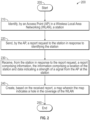
- FIG. 2 is a flow chart setting forth the general stages involved in a method 200 consistent with an embodiment of the disclosure for providing a Quality of Service (QoS) based wireless coverage map.
- Method 200 may be implemented using first access point 120 and mapping server 115 as described above with respect to FIG. 1 . Ways to implement the stages of method 200 will be described in greater detail below.
- QoS Quality of Service
- Method 200 may begin at starting block 205 and proceed to stage 210 where first AP 120 may identify station 110.
- station 100 may have roamed away from first AP 120 on WLAN 105 and may have roamed to a cellular network.
- first AP 120 may identify station 110 by determining that station 110 has roamed away from first AP 120.
- first AP 120 may periodically request a non-associated, but visible to first AP 120, station to report its view of WLAN 105's infrastructure (e.g., first AP 120, second AP 125, and third AP 130).
- first AP 120 may scan its surrounding wireless medium and see stations (e.g., station 110) that may not be associated with first AP 120.
- First AP 120 may identify these non-associated, yet visible stations as stations that could report their view of WLAN 105's infrastructure.
- first AP 120 may advance to stage 220 where first AP 120 may send a report request to station 110 in response to identifying station 110.
- first AP 120 may send a report request to station 110.
- the report request may comprise, but is not limited to, an MBO beacon report request.
- first AP 120 may send the report request to station 110 in response to identifying station 110 in stage 220
- method 200 may continue to stage 230 where first AP 120 may receive, from station 110 in response to the report request, a report 135 comprising information.
- the information may comprise a location of station 110 and data indicating a strength of a signal from first AP 120 at station 110.
- station 110 may scan its surrounding wireless medium and create a report.
- the report may comprise an MBO beacon report for example.
- station 110 may also include in the beacon report, location information (e.g., GPS coordinates) corresponding to its current location.
- location information e.g., GPS coordinates
- FIG. 1 illustrates an example report 135 (e.g., beacon report).
- station 110 may provide its current location as latitude 49.298518 and longitude 123.13771.
- GPS coordinates are an example and station 110 may provide its current location using processes other than GPS and may use indicators other than coordinates.
- report 135 may include the strength of the signal from first AP 120, second AP 125, and third AP 130 as seen by station 110 at its current location.
- These strengths of the signals may comprise, for example, an RSSI of -87 dBM for first AP 120 (i.e., AP1), an RSSI of -92 dBM for second AP 125 (i.e., AP2), and an RSSI of -94 dBM for third AP 130 (i.e., AP3).
- station 110 may not be associated with an AP in WLAN 105, report 135, including the location information of station 110, may be reported to first AP 120.
- first AP 120 may continue to request a report (e.g., request an MBO Beacon Report plus location) from station 110.
- a report e.g., request an MBO Beacon Report plus location
- station 110 may continue to report its location (e.g., its GPS coordinates) along with the strength of signals of WLAN 105's APs in beacon reports to first AP 120 as station 110 moves.
- station 110 may send report 135 to first AP 120 that may forward it to mapping server 115 noting that station 110 has roamed off WLAN 105.
- station 110 may send report 135 to mapping server 115 over a network other than WLAN 105, for example, a cellular network to which station 110 may have roamed.
- station 110 may initiate its own beacon report and transmit it to mapping server 115 over the cellular network.
- mapping server 115 may create, based on received report 135, a map.
- the map may indicate a hole or holes in the coverage of WLAN 105.
- mapping server 115 may create a dark map for WLAN 105 that may comprise a map indicating coverage holes in the coverage area of WLAN 105, for example, per access (e.g., QoS) category.
- a coverage hole may comprise an event where a station is outside the coverage boundaries of WLAN 105's APs.
- Embodiments of the disclosure may build a QoS aware dark map that may identify coverage areas of WLAN 105 based on the QoS from a station's view. For example, embodiments of the disclosure may identify holes (i.e., dead spots) for QoS levels comprising, but not limited to, data services, voice services, and video (e.g., High Definition (HD) video) services based on an AP density view from the station.
- QoS levels comprising, but not limited to, data services, voice services, and video (e.g., High Definition (HD) video) services based on an AP density view from the station.
- HD High Definition
- FIG. 3 illustrates coverage for a plurality of QoS levels.
- acceptable strength of signals of the APs may vary with the type of service being consumed.
- -68 dBM may be the lowest strength of signal.
- a lower strength of signal may be considered a hole for HD video service.
- voice service 310 -71 dBM may be the lowest strength of signal.
- a lower strength of signal may be considered a hole for voice service.
- data service 315 -73 dBM may be the lowest strength of signal.
- a lower strength of signal may be considered a hole for data service. Any strength of signal lower than -91 dBM may be considered a hole for any service type 320.
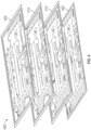
- FIG. 4 illustrates a plurality of maps 400 (e.g., dark maps) corresponding to a plurality of QoS levels.
- map 405 may correspond to HD video service
- map 410 may correspond to voice service
- map 415 may correspond to data service
- map 420 may comprise a floor plan for the area.
- the dark areas in plurality of maps 400 may indicate service holes for the given service type. As can be seen from FIG. 4 , the number of holes increase and grow larger as the QoS level increases from data to HD video. This may be because stronger signals may be needed for higher service quality.
- mapping server 115 may use the following network parameters in order to combine both an infrastructure view and a client (i.e., station) view for more accurate QoS aware coverage dark map production.
- These network parameters may comprise, but are not limited to: i) Received Signal to Noise Indicator (RSNI) and Radio Signal to Interference Noise Ratio (SiNR); ii) Enhanced Distributed Channel Access (EDCA); iii) backhaul channel quality state index; iv) network contention; v) histogram of transmit data rates; and vi) channel utilization QoS Enhanced Basic Service Set (QBSS).
- RSNI Received Signal to Noise Indicator
- SiNR Radio Signal to Interference Noise Ratio
- EDCA Enhanced Distributed Channel Access
- QBSS QoS Enhanced Basic Service Set
- mapping server 115 may first generate a QoS aware dark map leveraging the beacon report based RSNI and the radio's SiNR readings. These parameters may quantify both Uplink (UL) and Downlink (DL) quality metrics that may influence QoS. With respect to EDCA, mapping server 115 may then evaluate contention backoff parameters CW min , CW max , and AIFSN, for example, mapped to individual QoS access categories. These EDCA parameters may influence the amount of TxOP from the station and radio (i.e., AP) and therefore may affect overall link capacity to meet minimum QoS for the station.
- mapping server 115 may evaluate the Backhaul Channel Quality State Index by measuring backhaul capacity along with channel state information and the number of mesh hops from the Root Access Point. For example, any CMAPs with mesh hops greater than three may fail to handle latency requirements for Voice and Video traffic.
- mapping server 115 may evaluate the amount of co-channel contention induced by nearby wireless rogue devices and persistent devices. In the presence of a Spectrum Analysis Engine (SaGE), mapping server 115 may accurately measure Interference Severity Index (ISI) metrics to determine a level of contention present at a localized RF neighborhood.
- SaGE Spectrum Analysis Engine
- mapping server 115 may monitor a network histogram of transmit rates from nearby stations. Based on this report, mapping server 115 may quantify an average Modulation and Code Scheme (MCS) index used at different network edges.
- MCS Modulation and Code Scheme
- mapping server 115 may measure average QBSS along with TxUtil and RxUtil on an AP and its immediate close neighbors to assess total channel utilization along with Receive (UL) and Transmit (DL) utilization in a localized cluster.
- QBSS along with TxUtil and RxUtil may dictate overall jitter and latency and thus may have an influence on the QoS level that may be offered at a local site.
- Data for the beacon reports may be continually written to mapping server 115 and statistical inference processes may be used to correct stochastic variation in both the AP signal strength (e.g., RSSI) and station location (e.g., GPS location) measurements.
- RSSI signal strength
- station location e.g., GPS location
- GPS location accuracy may vary, however, using statistical methods over time, the location and relative RSSI estimates may converge with much better accuracy giving a clear picture of the dark map.
- mapping server 115 may build both the dark map (showing the coverage holes / dead zones) and also the DL signal strength observed by clients (e.g., stations) that may be near to APs (e.g., by periodically querying beacon reports from these stations). Mapping server 115 may now be able to build a service-level dark map model leveraging historical data from these devices where it may estimate levels of service that the clients can handle.
- mapping server 115 may be able to create statistical edges for WLAN 105 where different types of applications (e.g., video, voice, and data) may function to satisfaction. Once mapping server 115 creates the map (e.g., dark map) in stage 240, method 200 may then end at stage 250.
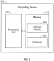
- FIG. 5 shows computing device 500.
- computing device 500 may include a processing unit 510 and a memory unit 515.
- Memory unit 515 may include a software module 520 and a database 525.
- software module 520 may perform, for example, processes for providing a Quality of Service (QoS) based wireless coverage map as described above with respect to FIG. 2 .
- Computing device 500 may provide an operating environment for station 110, mapping server 115, first AP 120, second AP 125, or third AP 130.
- Station 110, mapping server 115, first AP 120, second AP 125, and third AP 130 may operate in other environments and are not limited to computing device 500.
- Computing device 500 may be implemented using a Wireless Fidelity (Wi-Fi) access point, a cellular base station, a tablet device, a mobile device, a smart phone, a telephone, a remote control device, a set-top box, a digital video recorder, a cable modem, a personal computer, a network computer, a mainframe, a router, a switch, a server cluster, a smart TV-like device, a network storage device, a network relay devices, or other similar microcomputer-based device.
- Computing device 500 may comprise any computer operating environment, such as hand-held devices, multiprocessor systems, microprocessor-based or programmable sender electronic devices, minicomputers, mainframe computers, and the like.
- Computing device 500 may also be practiced in distributed computing environments where tasks are performed by remote processing devices.
- the aforementioned systems and devices are examples and computing device 500 may comprise other systems or devices.
- Embodiments of the disclosure may comprise a method for providing a Quality of Service (QoS) based wireless coverage map.
- the method may comprise identifying, by an Access Point (AP) in a Wireless Local Area Network (WLAN), a station; sending, by the AP, a report request to the station in response to identifying the station; and receiving, from the station in response to the report request, a report comprising information, the information comprising a location of the station and data indicating a strength of a signal from the AP at the station.
- AP Access Point
- WLAN Wireless Local Area Network
- Identifying the station may comprise determining that the station has roamed away from the AP. Identifying the station may comprise determining that the station has roamed away from the AP to a cellular network. Identifying the station may comprise determining that the station is visible by the AP and not associated with the AP.
- Receiving the report may comprise receiving the report by the AP over the WLAN.
- the method may further comprise forwarding the report to a mapping server.
- Receiving the report may comprise receiving the report by a mapping server over a cellular network. Receiving the report may comprise receiving the report wherein the information further comprises data indicating a strength of a signal from another AP at the station.
- the method may further comprise creating, based on the received report, a map wherein the map indicates a hole in the coverage of the WLAN.
- the method may further comprise creating, based on the received report, a plurality of maps wherein each of the plurality of maps indicates a hole in the coverage of the WLAN for a corresponding plurality of service levels.
- Embodiments of the disclosure may comprise a system for providing a Quality of Service (QoS) based wireless coverage map.
- the system may comprise a memory storage and a processing unit disposed in an Access Point (AP), the processing unit coupled to the memory storage.
- the processing unit may be operative to determine that a station has roamed away from the AP, send a report request to the station in response to determining that the station has roamed away from the AP, and receive, from the station in response to the report request, a report comprising information, the information comprising a location of the station and data indicating a strength of a signal from the AP at the station.
- the processing unit being operative to determine that the station has roamed away from the AP may comprise the processing unit being operative to determine that the station has roamed away from the AP to a cellular network.
- the report may be received over a Wireless Local Area Network (WLAN) in which the AP is disposed.
- WLAN Wireless Local Area Network
- the processing unit may be further operative to forward the report to a mapping server.
- the information may further comprise data indicating a strength of a signal from another AP at the station.
- Embodiments of the disclosure may comprise a method for providing a Quality of Service (QoS) based wireless coverage map.
- the method may comprise determining, by a station, that the station has roamed away from an Access Point (AP) in a Wireless Local Area Network (WLAN) to a cellular network; creating, by the station in response to determining that the station has roamed away from the AP, a report comprising information, the information comprising a location of the station and data indicating a strength of a signal from the AP at the station; and sending the report to a mapping server.
- AP Access Point
- WLAN Wireless Local Area Network
- the method may further comprise creating the report wherein the information may further comprise data indicating a strength of a signal from another AP at the station.
- Sending the report to the mapping server may comprise sending the report to the mapping server over the cellular network.
- the method may further comprise creating, based on the received report, a map wherein the map indicates a hole in the coverage of the WLAN.
- the method may further comprise creating, based on the received report, a plurality of maps wherein each of the plurality of maps indicates a hole in the coverage of the WLAN for a corresponding plurality of service levels.
- Embodiments of the disclosure may be implemented as a computer process (method), a computing system, or as an article of manufacture, such as a computer program product or computer readable media.
- the computer program product may be a computer storage media readable by a computer system and encoding a computer program of instructions for executing a computer process on one or more processors so as to cause any of the method described herein to be carried out
- the computer program product may also be a propagated signal on a carrier readable by a computing system and encoding a computer program of instructions for executing a computer process. Accordingly, the present disclosure may be embodied in hardware and/or in software (including firmware, resident software, micro-code, etc.).
- embodiments of the present disclosure may take the form of a computer program product on a computer-usable or computer-readable storage medium having computer-usable or computer-readable program code embodied in the medium for use by or in connection with an instruction execution system.
- a computer-usable or computer-readable medium may be any medium that can contain, store, communicate, propagate, or transport the program for use by or in connection with the instruction execution system, apparatus, or device.
- the computer-usable or computer-readable medium may be, for example but not limited to, an electronic, magnetic, optical, electromagnetic, infrared, or semiconductor system, apparatus, device, or propagation medium. More specific computer-readable medium examples (a non-exhaustive list), the computer-readable medium may include the following: an electrical connection having one or more wires, a portable computer diskette, a random access memory (RAM), a read-only memory (ROM), an erasable programmable read-only memory (EPROM or Flash memory), an optical fiber, and a portable compact disc read-only memory (CD-ROM).
- RAM random access memory
- ROM read-only memory
- EPROM or Flash memory erasable programmable read-only memory
- CD-ROM portable compact disc read-only memory
- the computer-usable or computer-readable medium could even be paper or another suitable medium upon which the program is printed, as the program can be electronically captured, via, for instance, optical scanning of the paper or other medium, then compiled, interpreted, or otherwise processed in a suitable manner, if necessary, and then stored in a computer memory.
- embodiments of the disclosure may be practiced in an electrical circuit comprising discrete electronic elements, packaged or integrated electronic chips containing logic gates, a circuit utilizing a microprocessor, or on a single chip containing electronic elements or microprocessors.
- Embodiments of the disclosure may also be practiced using other technologies capable of performing logical operations such as, for example, AND, OR, and NOT, including but not limited to, mechanical, optical, fluidic, and quantum technologies.
- embodiments of the disclosure may be practiced within a general purpose computer or in any other circuits or systems.
- Embodiments of the disclosure may be practiced via a system-on-a-chip (SOC) where each or many of the elements illustrated in FIG. 1 may be integrated onto a single integrated circuit.
- SOC system-on-a-chip
- Such an SOC device may include one or more processing units, graphics units, communications units, system virtualization units and various application functionality all of which may be integrated (or "burned") onto the chip substrate as a single integrated circuit.
- the functionality described herein with respect to embodiments of the disclosure may be performed via application-specific logic integrated with other components of computing device 500 on the single integrated circuit (chip).
- Embodiments of the present disclosure are described above with reference to block diagrams and/or operational illustrations of methods, systems, and computer program products according to embodiments of the disclosure.
- the functions/acts noted in the blocks may occur out of the order as shown in any flowchart.
- two blocks shown in succession may in fact be executed substantially concurrently or the blocks may sometimes be executed in the reverse order, depending upon the functionality/acts involved.
Landscapes
- Engineering & Computer Science (AREA)
- Computer Networks & Wireless Communication (AREA)
- Signal Processing (AREA)
- Computer Security & Cryptography (AREA)
- Mobile Radio Communication Systems (AREA)
Claims (13)
- Ein Verfahren, das Folgendes aufweist:Identifizieren (210) einer Station (110) durch einen Access Point, AP, (120) in einem drahtlosen lokalen Netzwerk, WLAN, (105), wobei das Identifizieren der Station (110) das Ermitteln aufweist, dass sich die Station (110) von dem AP (120) wegbewegt hat;Senden (220), durch den AP (120), einer Berichtsanforderung an die Station (110) als Antwort auf das Identifizieren der Station (110); undEmpfangen (230) eines Berichts, der Informationen aufweist, von der Station (110) als Antwort auf die Berichtsanforderung,die Informationen weisen einen Standort der Station (110) und Daten auf, die eine Stärke eines Signals von einem AP (120) an der Station (110) anzeigen, wobei das Verfahren ferner das Erzeugen (240) einer Vielzahl von Karten durch einen Mapping-Server (115) auf der Grundlage des empfangenen Berichts aufweist, wobei jede der Vielzahl von Karten eine Lücke in der Abdeckung des WLAN (105)für eine entsprechende Vielzahl von Dienstebenen anzeigt.
- Das Verfahren nach Anspruch 1, wobei das Identifizieren der Station (110) das Ermitteln aufweist, dass die Station (110) sich von einem AP (120) zu einem zellularen Netzwerk wegbewegt hat.
- Das Verfahren nach Anspruch 1 oder 2, wobei das Identifizieren der Station (110) das Ermitteln aufweist, dass die Station (110) durch den AP (120) sichtbar und nicht mit dem AP (120) verbunden ist.
- Das Verfahren nach einem der vorhergehenden Ansprüche, wobei der Empfang des Berichts den Empfang des Berichts durch den AP (120) über das WLAN (105)aufweist.
- Das Verfahren nach einem der vorhergehenden Ansprüche weist ferner das Weiterleiten des Berichts an einen Mapping-Server(115) auf.
- Das Verfahren nach einem der vorhergehenden Ansprüche, wobei das Empfangen des Berichts das Empfangen des Berichts durch einen Mapping-Server (115) über ein zellulares Netzwerk aufweist.
- Das Verfahren nach einem der vorhergehenden Ansprüche, wobei das Empfangen des Berichts das Empfangen des Berichts aufweist, wobei die Information weiterhin Daten aufweist, die eine Stärke eines Signals von einem anderen AP (120) an der Station (110) anzeigen.
- Ein System, das Folgendes aufweist:einen Speicher; undeine Verarbeitungseinheit, die in einem Access Point, AP, (120) eines drahtlosen lokalen Netzwerks, WLAN, (105)und einem Mapping-Server (115) angeordnet ist; wobei die Verarbeitungseinheit mit dem Speicher gekoppelt ist, wobei die Verarbeitungseinheit in der Lage ist:zu ermitteln, dass sich eine Station (110) von einem AP (120) wegbewegt hat,zu senden (220) einer Berichtsanforderung an die Station (110) als Antwort auf das Ermitteln, dass sichd ie Station(110) von dem AP (120) wegbewegt hat, undzu empfangen (230) eines Berichts, der Informationen aufweist, von der Station (110) als Antwort auf die Berichtsanforderung,die Informationen weisen einen Standort der Station (110) und Daten auf,die eine Stärke eines Signals von einem AP (120) an der Station (110) anzeigen, wobei der Mapping-Server (115) in der Lage ist auf der Grundlage des empfangenen Berichts eine Vielzahl von Karten zu erzeugen (240), wobei jede der Vielzahl von Karten eine Lücke in der Abdeckung des WLAN (105) für eine entsprechende Vielzahl von Dienstebenen anzeigt.
- Das System nach Anspruch 8,
wobei die Verarbeitungseinheit, in der Lage ist zu ermitteln, dass die Station (110) sich von dem AP (120) wegbewegt hat, die Verarbeitungseinheit aufweist, die in der Lage ist zu ermitteln, dass die Station (110) sich von dem AP (120) zu einem zellularen Netzwerk wegbewegt hat. - Das System nach Anspruch 8 oder 9, wobei eines oder mehrere der folgenden Merkmale beansprucht werden:die Meldung wird über das WLAN empfangen (105);die Verarbeitungseinheit ist ferner in der Lage, den Bericht an den Mapping-Server (115) weiterzuleiten;die Informationen außerdem Daten aufweisen, die die Stärke eines Signals von einem anderen AP (120) an der Station (110) anzeigen.
- Ein Verfahren, das Folgendes aufweist:Ermitteln durch eine Station (110), dass die Station (110) sich vom Access Point, AP,(120) in einem drahtlosen lokalen Netzwerk, WLAN, (105) zu einem zellularen Netzwerk wegbewegt hat;Erzeugen eines Berichts, der Informationen aufweist, von der Station (110) als Antwort auf das Bestimmen, dass die Station (110) sich von dem AP (120) wegbewegt hat, die Informationen weisen einen Standort der Station (110) und Daten auf, die eine Stärke eines Signals von dem AP (120) an der Station (110) anzeigen; undSenden des Berichts an einen Mapping-Server (115), wobei das Verfahren ferner aufweist, dass der Mapping-Server (115) auf der Grundlage des empfangenen Bericht eine Vielzahl von Karten erzeugt, wobei jede der Vielzahl von Karten eine Lücke in der Abdeckung des WLAN (105) für eine entsprechende Vielzahl von Dienstebenen anzeigt.
- Das Verfahren nach Anspruch 11, wobei eines oder beide der folgenden Merkmale beansprucht werden:Erstellen des Berichts weist das Erstellen des Berichts auf, wobei die Informationen ferner Daten aufweisen, die eine Stärke eines Signals von einem anderen AP (120) an der Station (110) anzeigen;Senden des Berichts an den Mapping-Server (115) weist das Senden des Berichts an den Mapping-Server(115) über das zellulare Netzwerk auf.
- Ein computerlesbares Speichermedium, das ein Computerprogramm mit Anweisungen zur Ausführung durch einen oder mehrere Prozessoren kodiert, die mit einer Station (110), einem Zugangspunkt (120) oder einem Mapping-Server (115), um die Station (110), den Access Point (120) oder den Mapping-Server (115) zu veranlassen, jeweils die Schritte des Verfahrens nach einem der Ansprüche 1 bis 7 oder 11 bis 13 durchzuführen.
Applications Claiming Priority (2)
| Application Number | Priority Date | Filing Date | Title |
|---|---|---|---|
| US16/566,450 US10820263B1 (en) | 2019-09-10 | 2019-09-10 | Quality of service (QoS) based wireless coverage map |
| PCT/US2020/049686 WO2021050417A1 (en) | 2019-09-10 | 2020-09-08 | Quality of service (qos) based wireless coverage map |
Publications (2)
| Publication Number | Publication Date |
|---|---|
| EP4029304A1 EP4029304A1 (de) | 2022-07-20 |
| EP4029304B1 true EP4029304B1 (de) | 2025-01-15 |
Family
ID=72614000
Family Applications (1)
| Application Number | Title | Priority Date | Filing Date |
|---|---|---|---|
| EP20776000.0A Active EP4029304B1 (de) | 2019-09-10 | 2020-09-08 | Dienstgüte (qos)-basierte karte der drahtlos-abdeckung |
Country Status (4)
| Country | Link |
|---|---|
| US (1) | US10820263B1 (de) |
| EP (1) | EP4029304B1 (de) |
| CN (1) | CN114391267A (de) |
| WO (1) | WO2021050417A1 (de) |
Families Citing this family (6)
| Publication number | Priority date | Publication date | Assignee | Title |
|---|---|---|---|---|
| US11405441B1 (en) * | 2019-09-26 | 2022-08-02 | United Services Automobile Association (Usaa) | Systems and methods for data pre-fetching |
| US11902873B2 (en) * | 2019-10-25 | 2024-02-13 | Huawei Technologies Co., Ltd. | System, method and apparatus for managing network resources |
| WO2022024198A1 (ja) * | 2020-07-27 | 2022-02-03 | 日本電信電話株式会社 | 通信システム、接続先制御方法、制御装置、及びプログラム |
| US20240324044A1 (en) * | 2021-07-14 | 2024-09-26 | Telefonaktiebolaget Lm Ericsson (Publ) | Methods, and Devices, of Estimating a Duration that a User Equipment, UE, is Unreachable Caused by a Coverage Hole in a Coverage Area of at Least one Access Node in a Telecommunication Network |
| CN116847371A (zh) * | 2022-03-25 | 2023-10-03 | 华为技术有限公司 | 覆盖空洞的检测方法和相关设备 |
| US12483906B2 (en) | 2023-01-12 | 2025-11-25 | Qualcomm Incorporated | Signal strength mapping for steering a client |
Citations (1)
| Publication number | Priority date | Publication date | Assignee | Title |
|---|---|---|---|---|
| US20120220291A1 (en) * | 2009-10-30 | 2012-08-30 | Telefonaktiebolaget L M Ericsson (Publ) | User equipment reporting of connection loss |
Family Cites Families (18)
| Publication number | Priority date | Publication date | Assignee | Title |
|---|---|---|---|---|
| US7293088B2 (en) * | 2003-07-28 | 2007-11-06 | Cisco Technology, Inc. | Tag location, client location, and coverage hole location in a wireless network |
| KR101001474B1 (ko) * | 2003-08-18 | 2010-12-14 | 에스케이 텔레콤주식회사 | 통화 품질 맵 작성 시스템 및 방법 |
| FR2876862B1 (fr) * | 2004-10-20 | 2007-04-27 | Cit Alcatel | Serveur de gestion pour la determination de cartographies de qualite de service percue au sein d'un reseau de communication mobile |
| US7499718B2 (en) | 2006-08-01 | 2009-03-03 | Cisco Technology, Inc. | Enhanced coverage hole detection in wireless networks |
| WO2010051838A1 (en) | 2008-11-05 | 2010-05-14 | Nokia Siemens Networks Oy | Method of improving coverage and optimisation in communication networks |
| US8107981B2 (en) | 2009-12-22 | 2012-01-31 | At&T Mobility Ii Llc | Wireless network interference management using geographic data |
| WO2012032376A1 (en) * | 2010-09-10 | 2012-03-15 | Nokia Corporation | Signal strength profiling |
| US8665743B2 (en) | 2011-10-28 | 2014-03-04 | Cisco Technology, Inc. | User behavior model and statistical transition map to assist advanced WLAN applications |
| US8885752B2 (en) * | 2012-07-27 | 2014-11-11 | Intel Corporation | Method and apparatus for feedback in 3D MIMO wireless systems |
| US8995255B2 (en) * | 2012-08-03 | 2015-03-31 | Intel Corporation | Coverage adjustment in E-UTRA networks |
| EP2891362A1 (de) * | 2012-08-28 | 2015-07-08 | Interdigital Patent Holdings, Inc. | Verfahren zur übergabe einer kommunikationsverbindung unter verwendung eines hauptbündels |
| WO2014042457A1 (ko) * | 2012-09-13 | 2014-03-20 | 엘지전자 주식회사 | 무선 통신 시스템에서 단말의 위치를 계산하기 위한 방법 및 그를 위한 장치 |
| US9313730B2 (en) * | 2013-02-15 | 2016-04-12 | Blackberry Limited | Public land mobile network (“PLMN”) discovery communications in a wireless network |
| US9603028B2 (en) * | 2013-12-31 | 2017-03-21 | Microsoft Technology Licensing, Llc | Management of community Wi-Fi network |
| US9301100B1 (en) * | 2015-07-20 | 2016-03-29 | Blackberry Limited | Indoor positioning systems and wireless fingerprints |
| US9913154B2 (en) * | 2015-07-21 | 2018-03-06 | Symbol Technologies, Llc | Wireless local area network coverage hole detection using mobile communication devices |
| MX2018005553A (es) * | 2015-11-02 | 2019-01-30 | Walmart Apollo Llc | Sistema y metodo para mapear cobertura de red inalambrica. |
| US11178156B2 (en) * | 2018-07-27 | 2021-11-16 | Verizon Patent And Licensing Inc. | Methods and systems for authenticating a reported geolocation of a mobile device |
-
2019
- 2019-09-10 US US16/566,450 patent/US10820263B1/en active Active
-
2020
- 2020-09-08 WO PCT/US2020/049686 patent/WO2021050417A1/en not_active Ceased
- 2020-09-08 CN CN202080063615.2A patent/CN114391267A/zh active Pending
- 2020-09-08 EP EP20776000.0A patent/EP4029304B1/de active Active
Patent Citations (1)
| Publication number | Priority date | Publication date | Assignee | Title |
|---|---|---|---|---|
| US20120220291A1 (en) * | 2009-10-30 | 2012-08-30 | Telefonaktiebolaget L M Ericsson (Publ) | User equipment reporting of connection loss |
Also Published As
| Publication number | Publication date |
|---|---|
| US10820263B1 (en) | 2020-10-27 |
| EP4029304A1 (de) | 2022-07-20 |
| WO2021050417A1 (en) | 2021-03-18 |
| CN114391267A (zh) | 2022-04-22 |
Similar Documents
| Publication | Publication Date | Title |
|---|---|---|
| EP4029304B1 (de) | Dienstgüte (qos)-basierte karte der drahtlos-abdeckung | |
| US9973935B2 (en) | SON-controlled DFS | |
| US10034189B2 (en) | Method and system for controlling radio parameter, network operation management apparatus, and radio station | |
| US9554289B2 (en) | Management method, apparatus, and system for coverage optimization | |
| CN103190174B (zh) | 在共存系统中获取信息的方法 | |
| CN106211204B (zh) | 一种获知非授权频谱无线环境的方法及其装置、终端 | |
| US9775121B1 (en) | Dynamic control of reference-signal transmission power based on reference signal coverage quality at or near half-way point between base stations | |
| CN103181209A (zh) | 用于限制相邻小区测量的报告的方法和装置 | |
| JP7220945B2 (ja) | サービス基地局のセルパラメータの自動的な最適化 | |
| US11937102B2 (en) | Optimizing utilization and performance of one or more unlicensed bands in a network | |
| US10764927B2 (en) | Systems and methods for dynamically selecting and adjusting energy detection thresholds (EDTs) in uncoordinated radio nodes deploying listen before talk to improve throughput on shared spectrum | |
| US10966099B2 (en) | Computing wireless deployment in an area | |
| US9961604B2 (en) | Radio network information management method and network device | |
| KR20160054899A (ko) | 무선 통신 시스템에서 안테나 파라미터를 최적화하기 위한 장치 및 방법 | |
| WO2020092541A2 (en) | Optimization of 5g (fifth generation) beam coverage and capacity and nsi (network slice instance) resource allocation | |
| US10687274B2 (en) | Selecting radio access for mobile terminals | |
| US11223962B2 (en) | Dynamic channel assignment driven by client analytics | |
| US10911167B2 (en) | Enhanced radio frequency (RF) management using active sensors | |
| EP3075185B1 (de) | Steuerung eines mobilfunknetzbetriebes mit interferenzbasierter metrik | |
| Barth et al. | Self-organization in 4G mobile networks: Motivation and vision | |
| US20220045909A1 (en) | Neighbor List Adaptive Mapping | |
| CN108633030A (zh) | 信道接入方法及装置 | |
| US11496912B2 (en) | Signaling assessment of wireless receivers | |
| US12413954B2 (en) | Systems and methods for roaming user equipment management services for wireless communications networks | |
| US20250310851A1 (en) | Network gap detection |
Legal Events
| Date | Code | Title | Description |
|---|---|---|---|
| STAA | Information on the status of an ep patent application or granted ep patent |
Free format text: STATUS: UNKNOWN |
|
| STAA | Information on the status of an ep patent application or granted ep patent |
Free format text: STATUS: THE INTERNATIONAL PUBLICATION HAS BEEN MADE |
|
| PUAI | Public reference made under article 153(3) epc to a published international application that has entered the european phase |
Free format text: ORIGINAL CODE: 0009012 |
|
| STAA | Information on the status of an ep patent application or granted ep patent |
Free format text: STATUS: REQUEST FOR EXAMINATION WAS MADE |
|
| 17P | Request for examination filed |
Effective date: 20220407 |
|
| AK | Designated contracting states |
Kind code of ref document: A1 Designated state(s): AL AT BE BG CH CY CZ DE DK EE ES FI FR GB GR HR HU IE IS IT LI LT LU LV MC MK MT NL NO PL PT RO RS SE SI SK SM TR |
|
| DAV | Request for validation of the european patent (deleted) | ||
| DAX | Request for extension of the european patent (deleted) | ||
| P01 | Opt-out of the competence of the unified patent court (upc) registered |
Effective date: 20230525 |
|
| GRAP | Despatch of communication of intention to grant a patent |
Free format text: ORIGINAL CODE: EPIDOSNIGR1 |
|
| STAA | Information on the status of an ep patent application or granted ep patent |
Free format text: STATUS: GRANT OF PATENT IS INTENDED |
|
| INTG | Intention to grant announced |
Effective date: 20240829 |
|
| GRAS | Grant fee paid |
Free format text: ORIGINAL CODE: EPIDOSNIGR3 |
|
| GRAA | (expected) grant |
Free format text: ORIGINAL CODE: 0009210 |
|
| STAA | Information on the status of an ep patent application or granted ep patent |
Free format text: STATUS: THE PATENT HAS BEEN GRANTED |
|
| AK | Designated contracting states |
Kind code of ref document: B1 Designated state(s): AL AT BE BG CH CY CZ DE DK EE ES FI FR GB GR HR HU IE IS IT LI LT LU LV MC MK MT NL NO PL PT RO RS SE SI SK SM TR |
|
| REG | Reference to a national code |
Ref country code: CH Ref legal event code: EP Ref country code: GB Ref legal event code: FG4D |
|
| REG | Reference to a national code |
Ref country code: DE Ref legal event code: R096 Ref document number: 602020044851 Country of ref document: DE |
|
| REG | Reference to a national code |
Ref country code: IE Ref legal event code: FG4D |
|
| REG | Reference to a national code |
Ref country code: NL Ref legal event code: MP Effective date: 20250115 |
|
| PG25 | Lapsed in a contracting state [announced via postgrant information from national office to epo] |
Ref country code: NL Free format text: LAPSE BECAUSE OF FAILURE TO SUBMIT A TRANSLATION OF THE DESCRIPTION OR TO PAY THE FEE WITHIN THE PRESCRIBED TIME-LIMIT Effective date: 20250115 |
|
| PG25 | Lapsed in a contracting state [announced via postgrant information from national office to epo] |
Ref country code: RS Free format text: LAPSE BECAUSE OF FAILURE TO SUBMIT A TRANSLATION OF THE DESCRIPTION OR TO PAY THE FEE WITHIN THE PRESCRIBED TIME-LIMIT Effective date: 20250415 |
|
| PG25 | Lapsed in a contracting state [announced via postgrant information from national office to epo] |
Ref country code: FI Free format text: LAPSE BECAUSE OF FAILURE TO SUBMIT A TRANSLATION OF THE DESCRIPTION OR TO PAY THE FEE WITHIN THE PRESCRIBED TIME-LIMIT Effective date: 20250115 |
|
| PG25 | Lapsed in a contracting state [announced via postgrant information from national office to epo] |
Ref country code: PL Free format text: LAPSE BECAUSE OF FAILURE TO SUBMIT A TRANSLATION OF THE DESCRIPTION OR TO PAY THE FEE WITHIN THE PRESCRIBED TIME-LIMIT Effective date: 20250115 |
|
| PG25 | Lapsed in a contracting state [announced via postgrant information from national office to epo] |
Ref country code: ES Free format text: LAPSE BECAUSE OF FAILURE TO SUBMIT A TRANSLATION OF THE DESCRIPTION OR TO PAY THE FEE WITHIN THE PRESCRIBED TIME-LIMIT Effective date: 20250115 |
|
| REG | Reference to a national code |
Ref country code: LT Ref legal event code: MG9D |
|
| PG25 | Lapsed in a contracting state [announced via postgrant information from national office to epo] |
Ref country code: IS Free format text: LAPSE BECAUSE OF FAILURE TO SUBMIT A TRANSLATION OF THE DESCRIPTION OR TO PAY THE FEE WITHIN THE PRESCRIBED TIME-LIMIT Effective date: 20250515 Ref country code: NO Free format text: LAPSE BECAUSE OF FAILURE TO SUBMIT A TRANSLATION OF THE DESCRIPTION OR TO PAY THE FEE WITHIN THE PRESCRIBED TIME-LIMIT Effective date: 20250415 |
|
| REG | Reference to a national code |
Ref country code: AT Ref legal event code: MK05 Ref document number: 1760619 Country of ref document: AT Kind code of ref document: T Effective date: 20250115 |
|
| PG25 | Lapsed in a contracting state [announced via postgrant information from national office to epo] |
Ref country code: HR Free format text: LAPSE BECAUSE OF FAILURE TO SUBMIT A TRANSLATION OF THE DESCRIPTION OR TO PAY THE FEE WITHIN THE PRESCRIBED TIME-LIMIT Effective date: 20250115 |
|
| PG25 | Lapsed in a contracting state [announced via postgrant information from national office to epo] |
Ref country code: LV Free format text: LAPSE BECAUSE OF FAILURE TO SUBMIT A TRANSLATION OF THE DESCRIPTION OR TO PAY THE FEE WITHIN THE PRESCRIBED TIME-LIMIT Effective date: 20250115 Ref country code: PT Free format text: LAPSE BECAUSE OF FAILURE TO SUBMIT A TRANSLATION OF THE DESCRIPTION OR TO PAY THE FEE WITHIN THE PRESCRIBED TIME-LIMIT Effective date: 20250515 |
|
| PG25 | Lapsed in a contracting state [announced via postgrant information from national office to epo] |
Ref country code: BG Free format text: LAPSE BECAUSE OF FAILURE TO SUBMIT A TRANSLATION OF THE DESCRIPTION OR TO PAY THE FEE WITHIN THE PRESCRIBED TIME-LIMIT Effective date: 20250115 Ref country code: GR Free format text: LAPSE BECAUSE OF FAILURE TO SUBMIT A TRANSLATION OF THE DESCRIPTION OR TO PAY THE FEE WITHIN THE PRESCRIBED TIME-LIMIT Effective date: 20250416 |
|
| PG25 | Lapsed in a contracting state [announced via postgrant information from national office to epo] |
Ref country code: AT Free format text: LAPSE BECAUSE OF FAILURE TO SUBMIT A TRANSLATION OF THE DESCRIPTION OR TO PAY THE FEE WITHIN THE PRESCRIBED TIME-LIMIT Effective date: 20250115 |
|
| PG25 | Lapsed in a contracting state [announced via postgrant information from national office to epo] |
Ref country code: SE Free format text: LAPSE BECAUSE OF FAILURE TO SUBMIT A TRANSLATION OF THE DESCRIPTION OR TO PAY THE FEE WITHIN THE PRESCRIBED TIME-LIMIT Effective date: 20250115 |
|
| PG25 | Lapsed in a contracting state [announced via postgrant information from national office to epo] |
Ref country code: SM Free format text: LAPSE BECAUSE OF FAILURE TO SUBMIT A TRANSLATION OF THE DESCRIPTION OR TO PAY THE FEE WITHIN THE PRESCRIBED TIME-LIMIT Effective date: 20250115 |
|
| PG25 | Lapsed in a contracting state [announced via postgrant information from national office to epo] |
Ref country code: DK Free format text: LAPSE BECAUSE OF FAILURE TO SUBMIT A TRANSLATION OF THE DESCRIPTION OR TO PAY THE FEE WITHIN THE PRESCRIBED TIME-LIMIT Effective date: 20250115 |
|
| PGFP | Annual fee paid to national office [announced via postgrant information from national office to epo] |
Ref country code: DE Payment date: 20250819 Year of fee payment: 6 |
|
| PG25 | Lapsed in a contracting state [announced via postgrant information from national office to epo] |
Ref country code: IT Free format text: LAPSE BECAUSE OF FAILURE TO SUBMIT A TRANSLATION OF THE DESCRIPTION OR TO PAY THE FEE WITHIN THE PRESCRIBED TIME-LIMIT Effective date: 20250115 |
|
| PGFP | Annual fee paid to national office [announced via postgrant information from national office to epo] |
Ref country code: GB Payment date: 20250923 Year of fee payment: 6 |
|
| REG | Reference to a national code |
Ref country code: DE Ref legal event code: R097 Ref document number: 602020044851 Country of ref document: DE |
|
| PGFP | Annual fee paid to national office [announced via postgrant information from national office to epo] |
Ref country code: FR Payment date: 20250903 Year of fee payment: 6 |
|
| PG25 | Lapsed in a contracting state [announced via postgrant information from national office to epo] |
Ref country code: EE Free format text: LAPSE BECAUSE OF FAILURE TO SUBMIT A TRANSLATION OF THE DESCRIPTION OR TO PAY THE FEE WITHIN THE PRESCRIBED TIME-LIMIT Effective date: 20250115 Ref country code: CZ Free format text: LAPSE BECAUSE OF FAILURE TO SUBMIT A TRANSLATION OF THE DESCRIPTION OR TO PAY THE FEE WITHIN THE PRESCRIBED TIME-LIMIT Effective date: 20250115 |
|
| PG25 | Lapsed in a contracting state [announced via postgrant information from national office to epo] |
Ref country code: RO Free format text: LAPSE BECAUSE OF FAILURE TO SUBMIT A TRANSLATION OF THE DESCRIPTION OR TO PAY THE FEE WITHIN THE PRESCRIBED TIME-LIMIT Effective date: 20250115 |
|
| PG25 | Lapsed in a contracting state [announced via postgrant information from national office to epo] |
Ref country code: SK Free format text: LAPSE BECAUSE OF FAILURE TO SUBMIT A TRANSLATION OF THE DESCRIPTION OR TO PAY THE FEE WITHIN THE PRESCRIBED TIME-LIMIT Effective date: 20250115 |
|
| PLBE | No opposition filed within time limit |
Free format text: ORIGINAL CODE: 0009261 |
|
| STAA | Information on the status of an ep patent application or granted ep patent |
Free format text: STATUS: NO OPPOSITION FILED WITHIN TIME LIMIT |
|
| 26N | No opposition filed |
Effective date: 20251016 |