EP4029233B1 - Dynamische erzeugung von massgeschneiderten farbselektionen - Google Patents
Dynamische erzeugung von massgeschneiderten farbselektionen Download PDFInfo
- Publication number
- EP4029233B1 EP4029233B1 EP20776291.5A EP20776291A EP4029233B1 EP 4029233 B1 EP4029233 B1 EP 4029233B1 EP 20776291 A EP20776291 A EP 20776291A EP 4029233 B1 EP4029233 B1 EP 4029233B1
- Authority
- EP
- European Patent Office
- Prior art keywords
- color
- colors
- location
- computer system
- mathematically
- Prior art date
- Legal status (The legal status is an assumption and is not a legal conclusion. Google has not performed a legal analysis and makes no representation as to the accuracy of the status listed.)
- Active
Links
Images


Classifications
-
- H—ELECTRICITY
- H04—ELECTRIC COMMUNICATION TECHNIQUE
- H04N—PICTORIAL COMMUNICATION, e.g. TELEVISION
- H04N1/00—Scanning, transmission or reproduction of documents or the like, e.g. facsimile transmission; Details thereof
- H04N1/46—Colour picture communication systems
- H04N1/56—Processing of colour picture signals
- H04N1/60—Colour correction or control
- H04N1/6058—Reduction of colour to a range of reproducible colours, e.g. to ink- reproducible colour gamut
-
- G—PHYSICS
- G06—COMPUTING OR CALCULATING; COUNTING
- G06T—IMAGE DATA PROCESSING OR GENERATION, IN GENERAL
- G06T11/00—Two-dimensional [2D] image generation
- G06T11/10—Texturing; Colouring; Generation of textures or colours
-
- G—PHYSICS
- G06—COMPUTING OR CALCULATING; COUNTING
- G06T—IMAGE DATA PROCESSING OR GENERATION, IN GENERAL
- G06T1/00—General purpose image data processing
- G06T1/20—Processor architectures; Processor configuration, e.g. pipelining
-
- H—ELECTRICITY
- H04—ELECTRIC COMMUNICATION TECHNIQUE
- H04N—PICTORIAL COMMUNICATION, e.g. TELEVISION
- H04N1/00—Scanning, transmission or reproduction of documents or the like, e.g. facsimile transmission; Details thereof
- H04N1/46—Colour picture communication systems
- H04N1/56—Processing of colour picture signals
- H04N1/60—Colour correction or control
- H04N1/603—Colour correction or control controlled by characteristics of the picture signal generator or the picture reproducer
Definitions
- the present invention relates to computer-implemented methods and systems for utilizing technological improvements to aid in identifying desired coat colors.
- Coatings can protect a coated material from corrosion, such as rust. Coatings can also provide an aesthetic function by providing a particular color and/or spatial appearance to an object. For example, most automobiles are coated using paints and various other coatings in order to protect the metal body of the automobile from the elements and also to provide aesthetic visual effects.
- Document US 2009/310153 relates to a color signal processing apparatus that includes a total amount calculating unit, a limit value calculating unit and a correcting unit.
- the total amount calculating unit calculates a total amount value of an input color signal in an output device color space which has, as color components, colors of coloring materials used in an output device.
- the limit value calculating unit calculates a limit value for limiting a total amount of a color signal, in accordance with the calculated total amount value.
- the correcting unit corrects the input color signal in the output device color space so that the total amount value of the input color signal becomes the calculated limit value or less.
- the present invention is defined by the appendend claims and comprises a computer system for dynamic generation of custom color selections.
- the computer system comprises one or more processors and one or more computer-readable media having stored thereon executable instructions that when executed by the one or more processors configure the computer system to perform various acts for dynamic generation of custom color selections.
- the computer system receives from a user an indication of a target color.
- the computer system also identifies a location of the target color within a mathematically-defined color space.
- the computer system identifies a location of a second color within the mathematically-defined color space.
- the computer system generates a first golden triangle within the mathematically-defined color space.
- the location of the target color comprises a first vertex of the first golden triangle.
- the location of the second color comprises a second vertex of the first golden triangle.
- a location of a third color comprises a third vertex of the first golden triangle.
- the computer system displays on a user interface an indication of the target color, the second color, and
- the present invention also comprises a method, executed on one or more processors, for dynamic generation of custom color selections.
- the method comprises receiving from a user an indication of a target color. Additionally, the method comprises identifying a location of the target color within a mathematically-defined color space. The method also comprises identifying a location of a second color within the mathematically-defined color space. In addition, the method comprises generating a first golden triangle within the mathematically-defined color space. The location of the target color comprises a first vertex of the first golden triangle. The location of the second color comprises a second vertex of the first golden triangle. A location of a third color comprises a third vertex of the first golden triangle. Further, the method comprises displaying on a user interface an indication of the target color, the second color, and the third color.
- the present invention further comprises a computer-readable media comprising one or more physical computer-readable storage media having stored thereon computer-executable instructions that, when executed at a processor, cause a computer system to perform a method for dynamic generation of custom color selections.
- the method comprises receiving from a user an indication of a target color. Additionally, the method comprises identifying a location of the target color within a mathematically-defined color space. The method also comprises identifying a location of a second color within the mathematically-defined color space. In addition, the method comprises generating a first golden triangle within the mathematically-defined color space. The location of the target color comprises a first vertex of the first golden triangle. The location of the second color comprises a second vertex of the first golden triangle. A location of a third color comprises a third vertex of the first golden triangle. Further, the method comprises displaying on a user interface an indication of the target color, the second color, and the third color.
- a computer system receives an indication of a target color from a user.
- the indication of the target color may be received in a variety of different forms.
- the user may provide a picture or sample of an object that the user wishes to match with the target color.
- the picture or sample of the object may be measured using a spectrophotometer to identify a target color associated with the picture or sample of the object.
- the user may provide information that selects a particular color by entering a color name, color code, or selecting a displayed color.
- the present invention is not limited to a particular means for receiving the indication of the target color from the user.
- the computer system may map the target color to a known color within a color database.
- the indication of the target color may comprise a swatch of fabric from a chair. An exact color match to the swatch of fabric may not be available as a coating. Accordingly, the computer system identifies within the color database, a nearest matching color to the swatch of fabric that is associated with the indication of the target color. Accordingly, the computer system maps the target color to a known color, that is available, within the color database.
- a "nearest match" may be determined using a number of different conventional color matching methods.
- the nearest/closest match is a color within a color database with the smallest distance in the mathematically-defined color space to the location of the searched color.
- an exact match to the indication of the target color may be available within the color database.
- the "target color” comprises the known color from the color database, whereas, the "indication of the target color” may be associated with a slightly different particular color.
- the computer system analyzes the colors within a mathematically-defined color space.
- the computer system proposes one or more accompanying colors that may be aesthetically pleasing when paired within the target color.
- the proposed one or more accompanying colors are identified by calculating a golden ratio triangle within the mathematically-defined color space and proposing colors from the color database that are most closely associated with the vertices of the golden ratio triangle.
- the colors from the color database that are most closely associated with the vertices of the golden ratio triangle may comprise the colors within a color database that have the smallest distance in the mathematically-defined color space to the vertices of the golden ratio triangle.
- Various additional or alternative methods may be used to propose different or additional accompanying colors.
- FIG. 1 depicts a schematic diagram of a system executing a color selection generation software application.
- the depicted system comprises a computer system 100 for dynamic generation of custom color selections.
- the computer system 100 comprises one or more processors 130 and one or more computer-readable media 140 that have stored thereon executable instructions that when executed by the one or more processors configure the computer system 100 to perform various acts.
- the one or more processors 130 and the one or more computer-readable media 140 may comprise local computer hardware and/or cloud-based computer hardware.
- the computer system 100 executes the color selection generation software application 120 using the one or more processor(s) 130 that execute computer executable instructions stored on the one or more computer-readable media 140.
- the color selection generation software application 120 is also in communication with an I/O interface 150.
- the I/O interface 150 may be in communication with a keyboard, a mouse, a digital display, a network communication interface, Bluetooth radios, GPS radios, and various other conventional computer I/O interfaces.
- the computer system 100 is programmed to receive, through the I/O interface 150, an indication of a target color 110.
- the color selection generation software application 120 also comprises a color selection generator 160.
- the color selection generator 160 comprises various modules for generating one or more proposed accompanying colors that may be aesthetically pleasing when paired within the target color 110.
- the modules include a golden ratio module 162, an opposite color module 164, a monochromatic color module 166, and a neighbor color module 168.
- a “module” comprises computer executable code and/or computer hardware that performs a particular function.
- a component as being a “module” is provided only for the sake of clarity and explanation and should not be interpreted to indicate that any particular structure of computer executable code and/or computer hardware is required, unless expressly stated otherwise.
- the terms “component”, “agent”, “manager”, “service”, “engine”, “virtual machine” or the like may also similarly be used.
- Figure 2 depicts a user interface 200 for a color selection generation software application 120.
- the color selection generator 160 generates proposed accompanying colors
- the user interface 200 displays the various colors.
- the user interface 200 may display the target color 110 along with various different categories 220(a-c) of accompanying colors 210.
- the different categories 220(a-c) include accompanying colors that fall within an intensity category 220a, a similar category 220b, and a combinations category 220c.
- the user interface 200 and these particular categories 220(a-c) are provided for the sake of example and explanation and do not limit the invention unless expressly stated otherwise.
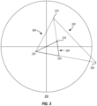
- Figure 3 depicts a target color 110 and a location of the target color 310 and potential proposed colors within a mathematically-defined color space 300.
- the mathematically-defined color space 300 may comprise the CIELAB color space.
- the CIELAB color spaces expresses color as three values: L* for lightness and a* and b* for color.
- L* for lightness
- a* and b* for color.
- the x-axis and the y-axis are represented by a* and b* respectively.
- the CIELAB color space is three-dimensional with the z-axis being represented by L* (lightness). Hue is measured as an angle within the a*-b* plane.
- Chroma is a measurement of a ray extending from the axis of the a*-b* plane. Saturation is measured as an angle in the a*-L* plane.
- CIELAB color space may be utilized, however, the present invention is not limited to the CIELAB color space and one of skill in the art would appreciate its application across many mathematically-defined color spaces.
- the color selection generation software application 120 After receiving from a user the indication of the target color 110, the color selection generation software application 120 communicates the target color 110 to the golden ratio module 162.
- the golden ratio module 162 identifies a location of the target color 310 within a mathematically-defined color space 300.
- the location of the target color 310 may comprise L*, a*, b* values within the CIELAB color space.
- the other color locations described herein may similar be calculated within the CIELAB color space.
- the golden ratio module 162 then identifies a location of a second color 320 within the mathematically-defined color space 300.
- the opposite color module 164 may identify the location of the second color 320 within the mathematically-defined color space 300 by calculating a set of second-color coordinates that are inverse to a set of coordinates associated with the location of the target color 310.
- the mathematically-defined color space 300 may be set upon a cartesian coordinate system, such as within the CIELAB color space. Within such a mathematically-defined color space 300, the location of the target color 310 may be designated as (+a*, +b*).
- the opposite color module 164 may identify the location of the second color 320 as being at (-a*, -b*).
- the generation of inverse colors in the RGB space is done by subtracting the RGB values from 255.
- the inverse of RGB [200, 200, 10] results in RGB [50, 50 245]. This can also be exemplified with an RGB color wheel.
- the golden ratio module 162 generates a first golden triangle 340 within the mathematically-defined color space 300.
- a "golden triangle” comprises an isosceles triangle having vertex angles of 36°, 72° and 72° or alternatively an isosceles triangle having vertex angles of 36°, 36° and 108°.
- the location of the target color 310 comprises a first vertex of the first golden triangle 340
- the location of the second color 320 comprises a second vertex of the first golden triangle 340
- a location of a third color 330 comprises a third vertex of the first golden triangle 350.
- the color selection generator 160 identifies respective colors within a color database that are closest to the location of the second color 320 and the location of the third color 330.
- the color database may be stored within the one or more computer-readable media 140.
- the color selection generator 160 may utilize a distance calculation to identify a second color within the color database that is closest to the location of the second color 320 and to identify a third color within the color database that is closest to the location of the third color 330.
- the computer system 100 displays on a user interface 200 an indication of the target color 110, the second color, and the third color.
- the golden ratio module 162 may generate a second golden triangle 400 within the mathematically-defined color space.
- Figure 4 depicts the location target color 310 and locations of potential proposed colors 320, 330, 410, and 430 within the mathematically-defined color space 300.
- the golden ratio module 162 utilizes the location of the target color 310 and the location of the third color 330, which was previously derived using the golden triangle ratios, in order to generate a location of a fourth color 410 within the mathematically-defined color space 300.
- the location of the target color 310 comprises a first vertex of the second golden triangle 400
- the location of the third color 330 comprises a second vertex of the second golden triangle 400
- a location of a fourth color 410 comprises a third vertex of the second golden triangle 400.
- Figure 4 further depicts that the golden ratio module 162 is capable of continuing to generate a third golden triangle 420 utilizing the location of the target color 310 and the location of the fourth color 410 to generate a location of a fifth color 430.
- the golden ratio module 162 may continue this process of generating new golden triangles utilizing the location of the target color 310 and sequentially generated new color locations (e.g., 330, 410, 430, etc.).
- the golden ratio module 162 may continue generating new golden ration triangles until the newly generated color locations no longer associate with new colors within the color database but instead are closer to the target color or previously identified potential accompanying colors than to new colors.
- the golden ratio module 162 may continue generating new golden ration triangles until the newly generated color locations are no longer visually distinguishable from the target color or previously identified potential accompanying colors than to other colors.
- the location of the target color 310 may be used in the generation of every golden triangle in order to ensure that the proposed colors maintain a relationship with the user provided target color 110.
- Figure 5 depicts a target color 110 and potential proposed colors within a mathematically-defined color space 300.
- the golden triangles 500, 520 are generated on an outward direction from the first golden triangle 340.
- the golden ratio module 162 can identify a new potential accompanying color based upon the location for the sixth color 510. Additionally, the golden ratio module 162 identifies that the location of the seventh color 530 is outside the mathematically-defined color space 300. Accordingly, the golden ratio module 162 determines that the location of the seventh color 530 is not mappable to a color within the color database. The golden ratio module 162 then prevents additional golden triangles from being created.
- the golden ratio module 162 may utilize the concept of the Golden Ratio as a natural way to pattern and proportion aesthetically pleasing combinations of proposed colors.
- the Golden Ratio represented by Phi or the Phi Ratio, is an irrational number, 0 ⁇ x ⁇ 1.618.
- the golden ratio module 162 uses the Golden Ratio to suggest computer-generated color palette(s) ("CGCP") associated to a user provided color.
- CGCP computer-generated color palette(s)
- the algorithms utilize the user's provided color to present computer-generated palettes based on the physical layout (1 dimension through many dimensions) of the mathematically-defined color space 300. The user can select 'more options' as much as needed to cascade through a number of different palette options by changing either the palette selection criteria or the mathematically-defined color space 300.
- the golden ratio module 162 may utilize a variety of ways to calculate the selection criteria. Most simplistically, the RGB (or CIELAB) of the customer's selected color can be modified by the golden ratio number, as depicted below in Table 1, which shows computer-generated color palette(s) (e.g., CGCP 1, CGCP 2, CGCP 3, CGCP 4) within respective columns.
- Table 1 shows computer-generated color palette(s) (e.g., CGCP 1, CGCP 2, CGCP 3, CGCP 4) within respective columns.
- the computer system 100 may additionally or alternatively, use a spiral method for selecting additional colors.
- Figure 6 depicts a golden logarithmic spiral 600 intersecting with locations of proposed colors 610(a-h) within a mathematically-defined color space 300.
- D one dimension of the physical layout (e.g. height).
- H A y ⁇ X where H is the computer-identified height dimension.
- W A ⁇ y ⁇ X where W is the computer identified width dimension.
- the computer system 100 can identify the color in that position and report it as the computer-generated color palette color.
- the computer system may also add more colors by varying the scalars, x and y.
- the computer system can shift the layout of the palette by ⁇ 1 (or other scalar) on the height, the width, or any other dimension.
- the computer system 100 may additionally or alternatively use lines as a selection criterion. For example, the computer system 100 may select color locations positioned consecutively ⁇ y0 ⁇ x away on the mathematically-defined color space 300 in single direction. The computer system 100 may also additionally or alternatively use triangles and tetrahedrons to select colors. The customer-selected color may be supported by another (1, 2, or 3) known harmonic's position in the mathematically-defined color space 300. The golden ratio is used to bisect the hypotenuse at a new point, which is the computer-selected color position.
- the computer system 100 can follow pentagons and pentagrams using circles of customer-selected colors, harmonics, or other computer-generated color positions to bisect and relate other physical layout positions in multi-dimensions.
- the computer system 100 calculates where the computer-selected color position will not exist in the physical (or digital) layout. Therefore, the calculation is bounded by the degrees of freedom in the original physical layout and may be scaled to it.
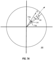
- Figure 7A depicts a location of the target color 310 and potential proposed colors within a mathematically-defined color space 300.
- the monochromatic color module 166 can generate a subset of neighbor colors 700 from the color database of available colors by selecting colors within the color database that are within positive fifteen degrees 710a and negative fifteen degrees 710b of hue variance from location of the target color 310 within the mathematically-defined color space 300.
- hue is measured as an angle within the a*, b* plane.
- hue variance from the location of the target color 310 may comprise an angular range from the target color 310 within the CIELAB color space. Nevertheless, other values may be used to a similar or different effect depending upon the desired outcome.
- the monochromatic color module 166 provides a technical and computational advantage to the computer system 100 by creating a "pie slice" within the mathematically-defined color space 300. By reducing the total possible set of colors to only those that have locations within the "pie slice,” the monochromatic color module 166 is capable of much more efficient and fast calculations due to the lower overheard of not requiring a search through the entire mathematically-defined color space 300 and/or the entire color database. Additionally, by creating the subset of neighbor colors 700 within the "pie slice” the monochromatic color module 166 creates a subset of colors that are capable of analysis using simple and efficient distance calculations. In some uses, however, the monochromatic color module 166 is not required to generate the subset of neighbor colors, but instead, operates within the entire mathematically-defined color space 300.
- the monochromatic color module 166 can also identify a subset of hue-similar colors within the subset of neighbor colors.
- the subset of hue-similar colors comprise colors that are within a particular threshold of hue difference from the target color 110.
- Figure 7B depicts an expanded portion of the mathematically-defined color space 300 of Figure 7A .
- the particular threshold of hue difference may comprise colors that are within an absolute value of ten degrees of a hue angle from the target color 110 within the mathematically-defined color space 300, such as the CIELAB color space. Nevertheless, other values may be used to a similar or different effect depending upon the desired outcome.
- the monochromatic color module 166 is not required to generate the subset of hue-similar colors from within the subset of neighbor colors, but instead, operates within the entire mathematically-defined color space 300 as it maps to colors available within the color database.
- the monochromatic color module 166 can also identify a subset of visually-similar colors within the subset of hue-similar colors.
- the subset of visually-similar colors comprise colors that are within a particular threshold of delta E from the target color.
- delta E comprises a distance metric defined by the International Commission on Illumination (CIE).
- CIE International Commission on Illumination
- the monochromatic color module 166 can identify a subset of visually-similar colors within the subset of hue-similar colors by calculating the ⁇ E between every color within the subset of hue-similar colors and the target color 110.
- the monochromatic color module 166 identifies a subset of visually similar colors that are within a threshold ⁇ E from the target color 110.
- the threshold ⁇ E may comprise a value of about 60. Nevertheless, other values may be used to a similar or different effect depending upon the desired outcome.
- the monochromatic color module 166 is not required to generate the subset of visually-similar colors from within the subset of hue-similar colors, but instead, operates within the entire mathematically-defined color space 300 as it maps to colors available within the color database.
- a chroma scale 740 and a lightness scale 750 are depicted.
- the depicted chroma scale 740 and a lightness scale 750 are provided only for the sake of clarity and explanation.
- One of skill in the art will appreciate that these values can be calculated and displayed without using respective scales. However, in order to maintain the clarity of the figures, they are depicted as scales herein.
- the monochromatic color module 166 can also identify a first set of proposed colors within the subset of visually-similar colors.
- the first set of proposed colors comprise colors that are both within a first negative threshold of chroma difference from the target color and within a first positive threshold of lightness difference from the target color.
- the first negative threshold of chroma difference may comprise a range of 0 to -10 and the first positive threshold of lightness difference may comprise a range of 10-20. It is believed that these particular thresholds provide desirable proposed colors due to the specific ranges of both the chroma and the lightness when compared to the target color 110. Nevertheless, other ranges may be used to a similar or different effect depending upon the desired outcome.
- the computer system 100 can then display on the user interface 200 the first set of proposed colors as potential accompanying colors to the target color.
- the monochromatic color module 166 can identify a second set of proposed colors within the subset of visually-similar colors.
- the second set of proposed colors comprises colors that are both within a first positive threshold of chroma difference from the target color and within a first negative threshold of lightness difference from the target color.
- the first positive threshold of chroma difference may comprise a range of 0 to 10
- the first negative threshold of lightness difference may comprise a range of -10 to -20. It is believed that these particular thresholds provide desirable proposed colors due to the specific ranges of both the chroma and the lightness when compared to the target color 110. Nevertheless, other ranges may be used to a similar or different effect depending upon the desired outcome.
- the computer system 100 can then display on the user interface 200 the second set of proposed colors as potential accompanying colors to the target color.
- the monochromatic color module 166 can identify a third set of proposed colors within the subset of visually-similar colors.
- the third set of proposed colors comprise colors that are both within a second negative threshold of chroma difference from the target color and within a second positive threshold of lightness difference from the target color.
- an absolute value of the second negative threshold of chroma difference is greater than the first negative threshold of chroma difference
- an absolute value of the second positive threshold of lightness difference is greater than the first positive threshold of lightness difference.
- the second negative threshold of chroma difference may comprise a range of 0 to -20 and the second positive threshold of lightness difference may comprise a range of 30 to 40.
- the computer system 100 can then display on the user interface 200 the third set of proposed colors as potential accompanying colors to the target color.
- the monochromatic color module 166 can identify a fourth set of proposed colors within the subset of visually-similar colors.
- the fourth set of proposed colors comprise colors that are both within a second positive threshold of chroma difference from the target color and within a second negative threshold of lightness difference from the target color.
- an absolute value of the second positive threshold of chroma difference is greater than the first positive threshold of chroma difference
- an absolute value of the second negative threshold of chroma difference is greater than the first positive threshold of lightness difference.
- the second positive threshold of chroma difference may comprise a range of 0 to 20 and the second negative threshold of lightness difference may comprise a range of -30 to -40.
- the computer system 100 can then display on the user interface 200 the fourth set of proposed colors as potential accompanying colors to the target color.
- Figure 8 depicts a location of a target color 310 and locations of potential proposed colors 800, 810 within a mathematically-defined color space 300.
- the neighbor color module 168 can identify a location of a first proposed neighbor color 800 within the mathematically-defined color space 300.
- the location of the first proposed neighbor color 800 is a positive threshold shift in chroma value from the location of the target color 310 within the mathematically-defined color space 300.
- the neighbor color module 168 identifies the first proposed neighbor color within the color database that is nearest to the location of a first proposed neighbor color 800.
- the positive threshold may comprise a chroma value of 15.
- the neighbor color module 168 also identifies a location of a second proposed neighbor color 810 within the mathematically-defined color space 300.
- the location of the second proposed neighbor color 810 is a negative threshold shift in chroma value from the location of the target color 310 within the mathematically-defined color space 300.
- the negative threshold may comprise a chroma value of -15.
- the neighbor color module 168 identifies the second proposed neighbor color within the color database that is nearest to the location of a second proposed neighbor color 810.
- the computer system 100 then displays, on the user interface, the first proposed neighbor color and the second proposed neighbor color.
- the methods, systems and computer-readable media disclosed herein provide several examples of technical improvements in the area of computer-generated color palette(s).
- Modern color databases are enormous and complex. Computers lack the intuitive ability to identify colors that are aesthetically pleasing when grouped together.
- Embodiments disclosed herein provide improved methods for efficiently generating computer-generated color palette(s).
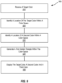
- Figure 9 depicts a flowchart of steps in a method 900 for the dynamic generation of custom color selections.
- Method 900 includes an act 910 of receiving a target color.
- Act 910 comprises receiving from a user an indication of a target color.
- a user provides an indication of a target color 110 to a computer system 100.
- the computer system 100 maps that indication of the target color 110 to an actual target color 110 that is present within a color database.
- method 900 includes an act 920 of identifying a location of the target color within a color space.
- Act 920 comprises identifying a location of the target color 310 within a mathematically-defined color space 300.
- the computer system 100 is configured to identify a location of the target color 310 within a mathematically-defined color space 300 of the target color 110 that was identified within the color database.
- the location of the target color 310 may be provided by information within the color database, whereas in other cases, the computer system 100 calculates the location.
- Method 900 also includes an act 930 of identifying a location of a second color within a color space.
- Act 930 comprises identifying a location of a second color 320 within the mathematically-defined color space 300.
- the opposite color module 164 can calculate an inverse of the coordinates of the location of the target color 310.
- the resulting "opposite location" may comprise the location of the second color 320.
- method 900 includes an act 940 of generating a first golden triangle within the color space.
- Act 940 comprises generating a first golden triangle within the mathematically-defined color space, wherein the location of the target color comprises a first vertex of the first golden triangle, the location of the second color comprises a second vertex of the first golden triangle, and a location of a third color comprises a third vertex of the first golden triangle.
- the golden ratio module 162 identifies a location of a third color 320 using the golden ratio. Using the location of a third color 320, the golden ratio module 162 is able to create a golden triangle within the mathematically-defined color space 300.
- method 900 includes an act 950 of displaying the target color, a second color and a third color.
- Act 950 comprises displaying on a user interface 200 an indication of the target color 110, the second color, and the third color.
- the user interface 200 displays various different categories 220(a-c) of accompanying colors 210, which can include the second color and the third color.
- the present invention may comprise or utilize a special-purpose or general-purpose computer system that includes computer hardware, such as, for example, one or more processors and system memory, as discussed in greater detail below.
- Embodiments within the scope of the present invention also include physical and other computer-readable media for carrying or storing computer-executable instructions and/or data structures.
- Such computer-readable media can be any available media that can be accessed by a general-purpose or special-purpose computer system.
- Computer-readable media that store computer-executable instructions and/or data structures are computer storage media.
- Computer-readable media that carry computer-executable instructions and/or data structures are transmission media.
- embodiments of the invention can comprise at least two distinctly different kinds of computer-readable media: computer storage media and transmission media.
- Computer storage media are physical storage media that store computer-executable instructions and/or data structures.
- Physical storage media include computer hardware, such as RAM, ROM, EEPROM, solid state drives (“SSDs”), flash memory, phasechange memory (“PCM”), optical disk storage, magnetic disk storage or other magnetic storage devices, or any other hardware storage device(s) which can be used to store program code in the form of computer-executable instructions or data structures, which can be accessed and executed by a general-purpose or special-purpose computer system to implement the disclosed functionality of the invention.
- Transmission media can include a network and/or data links which can be used to carry program code in the form of computer-executable instructions or data structures, and which can be accessed by a general-purpose or special-purpose computer system.
- a "network" is defined as one or more data links that enable the transport of electronic data between computer systems and/or modules and/or other electronic devices.
- program code in the form of computer-executable instructions or data structures can be transferred automatically from transmission media to computer storage media (or vice versa).
- program code in the form of computer-executable instructions or data structures received over a network or data link can be buffered in RAM within a network interface module (e.g., a "NIC"), and then eventually transferred to computer system RAM and/or to less volatile computer storage media at a computer system.
- a network interface module e.g., a "NIC”
- computer storage media can be included in computer system components that also (or even primarily) utilize transmission media.
- Computer-executable instructions comprise, for example, instructions and data which, when executed at one or more processors, cause a general-purpose computer system, special-purpose computer system, or special-purpose processing device to perform a certain function or group of functions.
- Computer-executable instructions may be, for example, binaries, intermediate format instructions such as assembly language, or even source code.
- the invention may be practiced in network computing environments with many types of computer system configurations, including, personal computers, desktop computers, laptop computers, message processors, hand-held devices, multi-processor systems, microprocessor-based or programmable consumer electronics, network PCs, minicomputers, mainframe computers, mobile telephones, PDAs, tablets, pagers, routers, switches, and the like.
- the invention may also be practiced in distributed system environments where local and remote computer systems, which are linked (either by hardwired data links, wireless data links, or by a combination of hardwired and wireless data links) through a network, both perform tasks.
- a computer system may include a plurality of constituent computer systems.
- program modules may be located in both local and remote memory storage devices.
- Cloud computing environments may be distributed, although this is not required. When distributed, cloud computing environments may be distributed internationally within an organization and/or have components possessed across multiple organizations.
- “cloud computing” is defined as a model for enabling on-demand network access to a shared pool of configurable computing resources (e.g., networks, servers, storage, applications, and services). The definition of “cloud computing” is not limited to any of the other numerous advantages that can be obtained from such a model when properly deployed.
- a cloud-computing model can be composed of various characteristics, such as on-demand self-service, broad network access, resource pooling, rapid elasticity, measured service, and so forth.
- a cloud-computing model may also come in the form of various service models such as, for example, Software as a Service (“SaaS”), Platform as a Service (“PaaS”), and Infrastructure as a Service (“laaS”).
- SaaS Software as a Service
- PaaS Platform as a Service
- laaS Infrastructure as a Service
- the cloud-computing model may also be deployed using different deployment models such as private cloud, community cloud, public cloud, hybrid cloud, and so forth.
- Some embodiments may comprise a system that includes one or more hosts that are each capable of running one or more virtual machines.
- virtual machines emulate an operational computing system, supporting an operating system and perhaps one or more other applications as well.
- each host includes a hypervisor that emulates virtual resources for the virtual machines using physical resources that are abstracted from view of the virtual machines.
- the hypervisor also provides proper isolation between the virtual machines.
- the hypervisor provides the illusion that the virtual machine is interfacing with a physical resource, even though the virtual machine only interfaces with the appearance (e.g., a virtual resource) of a physical resource. Examples of physical resources including processing capacity, memory, disk space, network bandwidth, media drives, and so forth.
Landscapes
- Engineering & Computer Science (AREA)
- Physics & Mathematics (AREA)
- General Physics & Mathematics (AREA)
- Theoretical Computer Science (AREA)
- Multimedia (AREA)
- Signal Processing (AREA)
- Image Processing (AREA)
- Color Image Communication Systems (AREA)
- Digital Computer Display Output (AREA)
- Controls And Circuits For Display Device (AREA)
- Processing Or Creating Images (AREA)
Claims (15)
- Ein Computersystem zur dynamischen Erzeugung von benutzerdefinierten Farbauswahlen, enthaltend:einen oder mehrere Prozessoren; undein oder mehrere computerlesbare Medien auf denen ausführbare Anweisungen gespeichert sind, die, wenn sie durch den einen oder die mehreren Prozessoren ausgeführt werden das Computersystem konfigurieren, dass es mindestens das Folgende ausführt:Erhalten einer Angabe zu einer Zielfarbe von einem Benutzer, Identifizieren einer Position der Zielfarbe innerhalb eines mathematisch definierten Farbraums;Identifizieren einer Position einer zweiten Farbe innerhalb des mathematisch definierten Farbraums;Erzeugen eines ersten goldenen Dreiecks innerhalb des mathematisch definierten Farbraums, wobei ein goldenes Dreieck ein gleichschenkliges Dreieck mit Eckwinkeln von 36°, 72° und 72° oder alternativ ein gleichschenkliges Dreieck mit Eckwinkeln von 36°, 36° und 108° umfasst,wobei: die Position der Zielfarbe einen ersten Eckpunkt des ersten goldenen Dreiecks umfasst, die Position der zweiten Farbe einen zweiten Eckpunkt des ersten goldenen Dreiecks umfasst und eine Position einer dritten Farbe einen dritten Eckpunkt des ersten goldenen Dreiecks umfasst, und Anzeigen auf einer Benutzeroberfläche eines Hinweises auf die Zielfarbe und die dritte Farbe.
- Das Computersystem gemäß Anspruch 1, wobei Erhalten einer Angabe zu einer Zielfarbe von einem Benutzer die Bereitstellung eines Bildes oder einer Probe eines Objekts umfasst und/oder wobei Erhalten einer Angabe zu einer Zielfarbe von einem Benutzer das Messen der Farbe des Bildes oder der Probe eines Objekts unter Verwendung eines Spektrometers umfasst, wobei die gemessene Farbe der Hinweis auf eine Zielfarbe ist.
- Das Computersystem gemäß irgendeinem der Ansprüche 1 oder 2, wobei die ausführbaren Anweisungen Anweisungen enthalten, die ausführbar sind, um das Computersystem zu konfigurieren, ein zweites goldenes Dreieck innerhalb des mathematisch definierten Farbraums zu erzeugen, wobei: die Position der Zielfarbe einen ersten Eckpunkt des zweiten goldenen Dreiecks umfasst, die Position der dritten Farbe einen zweiten Eckpunkt des zweiten goldenen Dreiecks umfasst, und eine Position einer vierten Farbe einen dritten Eckpunkt des zweiten goldenen Dreiecks umfasst, und Anzeigen auf einer Benutzeroberfläche eines Hinweises auf die Zielfarbe, die dritte Farbe und die vierte Farbe, bevorzugt umfasst die dritte Farbe eine spezifische Farbe, ausgewählt aus einer Farbdatenbank, die sich am nächsten der Position der dritten Farbe innerhalb des mathematisch definierten Farbraums befindet, und/oder wobei die vierte Farbe eine spezifische Farbe, ausgewählt aus einer Farbdatenbank, die sich am nächsten der Position der vierten Farbe innerhalb des mathematisch definierten Farbraums befindet, umfasst.
- Das Computersystem gemäß irgendeinem der Ansprüche 1 bis 3, wobei das Identifizieren einer Position einer zweiten Farbe innerhalb des mathematisch definierten Farbraums das Berechnen eines Satzes von zweiten Farbkoordinaten umfasst, die invers zu einem Satz von Koordinaten assoziiert mit einer Zielfarbe sind, insbesondere invers zu den a*- und b*-Koordinaten in einem CIELAB-Farbraum.
- Das Computersystem gemäß irgendeinem der Ansprüche 1 bis 4, wobei die ausführbaren Anweisungen Anweisungen enthalten, die ausführbar sind, um das Computersystem zu konfigurieren, dass es die zweite Farbe auf der Benutzeroberfläche anzeigt.
- Das Computersystem nach irgendeinem der Ansprüche 1 bis 5, wobei die zweite Farbe eine spezifische Farbe umfasst, die aus einer Farbdatenbank ausgewählt ist, die sich am nächsten der Position der zweiten Farbe innerhalb des mathematisch definierten Farbraums befindet.
- Das Computersystem nach irgendeinem der Ansprüche 1 bis 6, wobei die dritte Farbe eine spezifische Farbe umfasst, die aus einer Farbdatenbank ausgewählt ist, die sich am nächsten der Position der dritten Farbe innerhalb des mathematisch definierten Farbraums befindet.
- Das Computersystem nach irgendeinem der Ansprüche 1 bis 7, wobei das Erhalten einer Angabe zu einer Zielfarbe von einem Benutzer umfasst: Empfangen einer bestimmten Farbe; und Identifizieren innerhalb einer Farbdatenbank einer am nächstliegenden passende Farbe zu der bestimmten Farbe, wobei Identifizieren einer Position der Zielfarbe innerhalb eines mathematisch definierten Farbraums das Identifizieren einer nächstliegenden passende Farbe, innerhalb einer Farbdatenbank, zu der Angabe einer Zielfarbe umfasst, wobei die nächstliegenden passende Farbe die Position der Zielfarbe ist.
- Das Computersystem nach irgendeinem der Ansprüche 1 bis 8, wobei die ausführbaren Anweisungen Anweisungen enthalten, die ausführbar sind, um das Computersystem wie folgt zu konfigurieren; Erzeugung einer Teilmenge von Nachbarfarben aus der Farbdatenbank von verfügbaren Farben, indem Farben innerhalb der Farbdatenbank ausgewählt werden, die innerhalb von positiver oder negativer fünfzehn Grad Farbtonabweichung zu der Zielfarbe innerhalb des mathematisch definierten Farbraums liegen, wobei die Zielfarbe bei einem a*- und b*-Koordinatenpaar innerhalb des CIELAB-Farbraums angeordnet ist.
- Das Computersystem nach irgendeinem der Ansprüche 1 bis 9, wobei die ausführbaren Anweisungen Anweisungen enthalten, die ausführbar sind, um das Computersystem wie folgt zu konfigurieren: Identifizieren einer Teilmenge von Farbton ähnlichen Farben innerhalb der Teilmenge von Nachbarfarben, wobei die Teilmenge von Farbton ähnlichen Farben Farben umfasst, die innerhalb eines bestimmten Schwellenwertes der Farbtondifferenz, wie beispielsweise 10 Grad, von der Zielfarbe liegen; Identifizieren einer Teilmenge von visuell ähnlichen Farben innerhalb der Teilmenge von farbtonähnlichen Farben, wobei die Teilmenge von visuell ähnlichen Farben Farben umfasst, die innerhalb eines bestimmten Schwellenwertes von Delta E, wie beispielsweise unter 60 oder 30 oder 20 oder 10 oder 5, der Zielfarbe liegen; Identifizieren eines ersten Satzes von vorgeschlagenen Farben innerhalb der Teilmenge von visuell ähnlichen Farben, wobei der erste Satz von vorgeschlagenen Farben Farben umfasst, die sowohl innerhalb eines ersten negativen Schwellenwertes der Farbsättigungsdifferenz, wie beispielsweise 0 bis -10, von der Zielfarbe als auch innerhalb eines ersten positiven Schwellenwertes der Helligkeitsdifferenz, wie beispielsweise 10 bis 20, von der Zielfarbe liegen; Identifizieren eines zweiten Satzes von vorgeschlagenen Farben innerhalb der Teilmenge von visuell ähnlichen Farben, wobei der zweite Satz von vorgeschlagenen Farben Farben umfasst, die sowohl innerhalb eines ersten positiven Schwellenwertes der Farbsättigungsdifferenz, wie beispielsweise 0 bis 10, von der Zielfarbe als auch innerhalb eines ersten negativen Schwellenwertes der Helligkeitsdifferenz, wie beispielsweise -10 bis -20, von der Zielfarbe liegen; und Anzeigen des ersten Satzes von vorgeschlagenen Farben und des zweiten Satzes von vorgeschlagenen Farben auf der Benutzeroberfläche.
- Das Computersystem gemäß irgendeinem der Ansprüche 1 bis 10, wobei der mathematisch definierte Farbraum der CIELAB-Farbraum ist, wobei L* die Helligkeit, a* der Rot/Grün-Wert und b* der Blau/Gelb-Wert ist und/oder der RGB-Farbraum ist.
- Das Computersystem gemäß irgendeinem der Ansprüche 1 bis 11, wobei die Identifizierung einer Position der jeweiligen Farben, insbesondere der Ziel-, zweiten und dritten Farben, innerhalb eines mathematisch definierten Farbraums im CIELAB-Farbraum erfolgt, wobei die Koordinaten der Positionen die a*- und b*-Werte im CIELAB-Farbraum umfassen.
- Das Computersystem nach irgendeinem der Ansprüche 1 bis 12, wobei die ausführbaren Anweisungen Anweisungen enthalten, die ausführbar sind, um das Computersystem wie folgt zu konfigurieren: Identifizieren eines dritten Satzes von vorgeschlagenen Farben innerhalb der Teilmenge von visuell ähnlichen Farben, wobei der dritte Satz von vorgeschlagenen Farben Farben umfasst, die sowohl innerhalb eines zweiten negativen Schwellenwerts der Farbsättigungsdifferenz, wie beispielsweise von 0 bis - 20, von der Zielfarbe als auch innerhalb eines zweiten positiven Schwellenwerts der Helligkeitsdifferenz, wie beispielsweise von 30 bis 40, von der Zielfarbe liegen, wobei: ein absoluter Wert des zweiten negativen Schwellenwerts der Farbsättigungsdifferenz größer ist als der erste negative Schwellenwert der Farbsättigungsdifferenz, und ein absoluter Wert des zweiten positiven Schwellenwerts der Helligkeitsdifferenz größer ist als der erste positive Schwellenwert der Helligkeitsdifferenz; Identifizieren eines vierten Satzes von vorgeschlagenen Farben innerhalb der Teilmenge von visuell ähnlichen Farben, wobei der vierte Satz von vorgeschlagenen Farben Farben umfasst, die sowohl innerhalb eines zweiten positiven Schwellenwerts der Farbsättigungsdifferenz, wie beispielsweise von 0 bis 20, von der Zielfarbe als auch innerhalb eines zweiten negativen Schwellenwerts der Helligkeitsdifferenz, wie beispielsweise von -30 bis -40, von der Zielfarbe liegen, wobei: ein absoluter Wert des zweiten positiven Schwellenwerts der Farbsättigungsdifferenz größer ist als der erste positive Schwellenwert der Farbsättigungsdifferenz, und ein absoluter Wert des zweiten negativen Schwellenwerts der Farbsättigungsdifferenz größer ist als der erste positive Schwellenwert der Helligkeitsdifferenz; und Anzeigen des dritten Satzes von vorgeschlagenen Farben und des vierten Satzes von vorgeschlagenen Farben auf der Benutzeroberfläche.
- Das Computersystem nach irgendeinem der Ansprüche 1 bis 13, wobei die ausführbaren Anweisungen Anweisungen enthalten, die ausführbar sind, um das Computersystem wie folgt zu konfigurieren: Identifizieren einer Position einer ersten vorgeschlagenen Nachbarfarbe innerhalb des mathematisch definierten Farbraums, wobei die Position der ersten vorgeschlagenen Nachbarfarbe eine positive Schwellenwertverschiebung im Farbsättigungswert, wie beispielsweise 15, von der Position der Zielfarbe innerhalb des mathematisch definierten Farbraums aufweist; Identifizieren der ersten vorgeschlagenen Nachbarfarbe innerhalb der Farbdatenbank, die der Position einer ersten vorgeschlagenen Nachbarfarbe am nächsten ist; Identifizieren einer Position einer zweiten vorgeschlagenen Nachbarfarbe innerhalb des mathematisch definierten Farbraums, wobei die Position der zweiten vorgeschlagenen Nachbarfarbe eine negative Schwellenwertverschiebung im Farbsättigungswert, wie beispielsweise 15, von der Position der Zielfarbe innerhalb des mathematisch definierten Farbraums aufweist; Identifizieren der zweiten vorgeschlagenen Nachbarfarbe innerhalb der Farbdatenbank, die der Position einer zweiten vorgeschlagenen Nachbarfarbe am nächsten ist; und Anzeigen, auf der Benutzeroberfläche, der ersten vorgeschlagenen Nachbarfarbe und der zweiten vorgeschlagenen Nachbarfarbe.
- Verfahren, ausgeführt auf einem oder mehreren Prozessoren, zur dynamischen Erzeugung von benutzerdefinierten Farbauswahlen gemäß irgendeinem der Ansprüche 1 bis 14 für ein Computersystem.
Applications Claiming Priority (2)
| Application Number | Priority Date | Filing Date | Title |
|---|---|---|---|
| US201962899679P | 2019-09-12 | 2019-09-12 | |
| PCT/US2020/050308 WO2021050813A1 (en) | 2019-09-12 | 2020-09-11 | Dynamic generation of custom color selections |
Publications (3)
| Publication Number | Publication Date |
|---|---|
| EP4029233A1 EP4029233A1 (de) | 2022-07-20 |
| EP4029233B1 true EP4029233B1 (de) | 2024-06-19 |
| EP4029233C0 EP4029233C0 (de) | 2024-06-19 |
Family
ID=72615967
Family Applications (1)
| Application Number | Title | Priority Date | Filing Date |
|---|---|---|---|
| EP20776291.5A Active EP4029233B1 (de) | 2019-09-12 | 2020-09-11 | Dynamische erzeugung von massgeschneiderten farbselektionen |
Country Status (7)
| Country | Link |
|---|---|
| US (1) | US11741640B2 (de) |
| EP (1) | EP4029233B1 (de) |
| CN (1) | CN114402353B (de) |
| AU (1) | AU2020233704B2 (de) |
| CA (1) | CA3150207C (de) |
| MX (1) | MX2022003081A (de) |
| WO (1) | WO2021050813A1 (de) |
Families Citing this family (3)
| Publication number | Priority date | Publication date | Assignee | Title |
|---|---|---|---|---|
| CN110865856B (zh) * | 2018-08-27 | 2022-04-22 | 华为技术有限公司 | 一种界面元素颜色显示方法及装置 |
| WO2023277878A1 (en) * | 2021-06-29 | 2023-01-05 | Hewlett-Packard Development Company, L.P. | Color gamut mapping |
| US20230183979A1 (en) * | 2021-12-15 | 2023-06-15 | Bmic Llc | Building materials and related methods |
Family Cites Families (56)
| Publication number | Priority date | Publication date | Assignee | Title |
|---|---|---|---|---|
| GB254649A (en) | 1926-03-22 | 1926-07-08 | Joseph Marcel Vogel | Improvements in colour meters or systems of displaying or determining colours on charts |
| JPS53138857U (de) | 1977-04-08 | 1978-11-02 | ||
| US4887217A (en) | 1985-01-04 | 1989-12-12 | The Sherwin-Williams Company | Process for manufacturing paints |
| US4966461A (en) | 1989-08-25 | 1990-10-30 | Hooper Donald H | Color identification system |
| US5311212A (en) | 1991-03-29 | 1994-05-10 | Xerox Corporation | Functional color selection system |
| US5254978A (en) | 1991-03-29 | 1993-10-19 | Xerox Corporation | Reference color selection system |
| US5615320A (en) | 1994-04-25 | 1997-03-25 | Canon Information Systems, Inc. | Computer-aided color selection and colorizing system using objective-based coloring criteria |
| US6081253A (en) | 1998-02-10 | 2000-06-27 | Bronson Color Company, Inc. | Method for generating numerous harmonious color palettes from two colors |
| US7228283B1 (en) | 2000-04-05 | 2007-06-05 | David Hornstein | Aesthetic profile collection |
| US6697079B2 (en) | 2001-03-15 | 2004-02-24 | Apple Computer, Inc. | Color palette providing cross-platform consistency |
| FR2838373A1 (fr) | 2002-04-10 | 2003-10-17 | Nathalie Baugas Carnec | Procede d'aide a la creation d'une gamme harmonique de teintes |
| US7502033B1 (en) * | 2002-09-30 | 2009-03-10 | Dale Axelrod | Artists' color display system |
| WO2004048910A2 (en) | 2002-11-21 | 2004-06-10 | The Sherwin-Williams Company | Method of color matching wood stains |
| US7230629B2 (en) | 2003-11-06 | 2007-06-12 | Behr Process Corporation | Data-driven color coordinator |
| US7193632B2 (en) | 2003-11-06 | 2007-03-20 | Behr Process Corporation | Distributed color coordination system |
| US7136074B2 (en) | 2004-08-02 | 2006-11-14 | Master Colors | Method and system of improved color selection |
| GB0420461D0 (en) | 2004-09-14 | 2004-10-20 | Bremer Trainor Michael | Colour system |
| US20060066629A1 (en) | 2004-09-30 | 2006-03-30 | Microsoft Corporation | System and method for color selection |
| KR100633144B1 (ko) | 2004-11-09 | 2006-10-11 | 삼성전자주식회사 | 색 관리방법 및 이를 적용한 색 관리장치 |
| EP1852826B1 (de) | 2006-05-03 | 2019-12-18 | BlackBerry Limited | Erzeugung einer dynamischen Themenfarbpalette |
| US7646392B2 (en) | 2006-05-03 | 2010-01-12 | Research In Motion Limited | Dynamic theme color palette generation |
| NL1033836C1 (nl) | 2007-05-11 | 2008-11-13 | Stijn Filippus Postema | Methode voor het samenstellen van harmonische kleurakkoorden. |
| US7864193B2 (en) * | 2007-07-02 | 2011-01-04 | International Business Machines Corporation | RGB color conversion palettes |
| US9134179B2 (en) * | 2007-07-11 | 2015-09-15 | Benjamin Moore & Co. | Color selecton system based on desired color emotion and color harmony |
| WO2009036210A1 (en) * | 2007-09-11 | 2009-03-19 | Rgb Light Limited | Two dimensional representation of color spaces |
| JP4618457B2 (ja) * | 2008-06-16 | 2011-01-26 | 富士ゼロックス株式会社 | 色信号処理装置、色変換装置、色信号処理プログラム、色変換プログラム |
| US9639983B2 (en) | 2009-07-22 | 2017-05-02 | Behr Process Corporation | Color selection, coordination and purchase system |
| US8319788B2 (en) | 2009-07-22 | 2012-11-27 | Behr Process Corporation | Automated color selection method and apparatus |
| US9542038B2 (en) | 2010-04-07 | 2017-01-10 | Apple Inc. | Personalizing colors of user interfaces |
| US8553045B2 (en) | 2010-09-24 | 2013-10-08 | Xerox Corporation | System and method for image color transfer based on target concepts |
| US9019296B1 (en) | 2010-11-19 | 2015-04-28 | Pure Home Corporation | Customized color selection for a design project |
| US8837820B2 (en) * | 2012-05-25 | 2014-09-16 | Xerox Corporation | Image selection based on photographic style |
| DE102012011873A1 (de) | 2012-06-13 | 2014-01-09 | Ferdinand Wülfing | Verfahren zur Erzeugung eines Farbenraumes mit Farben auf einem Informationsträger, ein Farbtarget zum Abgleich von Ein- und Ausgabegeräten und Verwendung eines solchen Farbtargets |
| WO2014087274A1 (en) | 2012-10-24 | 2014-06-12 | Koninklijke Philips N.V. | Assisting a user in selecting a lighting device design |
| US10387938B2 (en) | 2012-10-30 | 2019-08-20 | Stylyze Llc | Automated color processing and selection platform |
| US9123149B2 (en) * | 2013-03-15 | 2015-09-01 | Columbia Insurance Company | Expert color system for color selection with color harmony and color emotion intelligence |
| US9582905B2 (en) | 2013-12-16 | 2017-02-28 | Adobe Systems Incorporated | Adverbial expression based color image operations |
| EP3134873A1 (de) | 2014-04-25 | 2017-03-01 | Sony Corporation | Verarbeitung digitaler fotografien als reaktion auf externe anwendungen |
| US10409822B2 (en) | 2014-05-06 | 2019-09-10 | Shutterstock, Inc. | Systems and methods for presenting ranked search results |
| US9524563B2 (en) * | 2014-06-26 | 2016-12-20 | Amazon Technologies, Inc. | Automatic image-based recommendations using a color palette |
| US9177391B1 (en) | 2014-06-26 | 2015-11-03 | Amazon Technologies, Inc. | Image-based color palette generation |
| US9401032B1 (en) | 2014-06-26 | 2016-07-26 | Amazon Technologies, Inc. | Image-based color palette generation |
| US9514543B2 (en) | 2014-06-26 | 2016-12-06 | Amazon Technologies, Inc. | Color name generation from images and color palettes |
| US9679532B2 (en) * | 2014-06-26 | 2017-06-13 | Amazon Technologies, Inc. | Automatic image-based recommendations using a color palette |
| US10223427B1 (en) | 2014-06-26 | 2019-03-05 | Amazon Technologies, Inc. | Building a palette of colors based on human color preferences |
| US9311889B1 (en) | 2014-06-26 | 2016-04-12 | Amazon Technologies, Inc. | Image-based color palette generation |
| US9135719B1 (en) | 2014-06-26 | 2015-09-15 | Amazon Technologies, Inc. | Color name generation from images and color palettes |
| US9727983B2 (en) | 2014-06-26 | 2017-08-08 | Amazon Technologies, Inc. | Automatic color palette based recommendations |
| US9785649B1 (en) * | 2014-09-02 | 2017-10-10 | Amazon Technologies, Inc. | Hue-based color naming for an image |
| US20160142625A1 (en) * | 2014-11-13 | 2016-05-19 | Lenovo (Singapore) Pte. Ltd. | Method and system for determining image composition attribute adjustments |
| US9798743B2 (en) | 2014-12-11 | 2017-10-24 | Art.Com | Mapping décor accessories to a color palette |
| US10585936B2 (en) | 2017-06-12 | 2020-03-10 | International Business Machines Corporation | Generating complementary colors for content to meet accessibility requirement and reflect tonal analysis |
| US10380650B2 (en) | 2017-07-26 | 2019-08-13 | Jehan Hamedi | Systems and methods for automating content design transformations based on user preference and activity data |
| US10593067B2 (en) | 2017-09-12 | 2020-03-17 | Jamison HILL | Intelligent systems and methods for dynamic color hierarchy and aesthetic design computation |
| US10706816B2 (en) | 2018-10-05 | 2020-07-07 | International Business Machines Corporation | Implementing a fault tolerant color palette |
| US20200379613A1 (en) * | 2019-05-31 | 2020-12-03 | Chameleon Power, Inc. | Distributed computing systems, graphical user interfaces, and processor-executable logic for provisioning phi-based color evaluation and harmonization |
-
2020
- 2020-09-11 EP EP20776291.5A patent/EP4029233B1/de active Active
- 2020-09-11 CN CN202080063771.9A patent/CN114402353B/zh active Active
- 2020-09-11 CA CA3150207A patent/CA3150207C/en active Active
- 2020-09-11 MX MX2022003081A patent/MX2022003081A/es unknown
- 2020-09-11 AU AU2020233704A patent/AU2020233704B2/en active Active
- 2020-09-11 US US17/018,618 patent/US11741640B2/en active Active
- 2020-09-11 WO PCT/US2020/050308 patent/WO2021050813A1/en not_active Ceased
Also Published As
| Publication number | Publication date |
|---|---|
| WO2021050813A1 (en) | 2021-03-18 |
| US20210082158A1 (en) | 2021-03-18 |
| CA3150207C (en) | 2024-03-12 |
| EP4029233C0 (de) | 2024-06-19 |
| AU2020233704A1 (en) | 2021-04-01 |
| CA3150207A1 (en) | 2021-03-18 |
| EP4029233A1 (de) | 2022-07-20 |
| AU2020233704B2 (en) | 2025-10-02 |
| CN114402353A (zh) | 2022-04-26 |
| US11741640B2 (en) | 2023-08-29 |
| CN114402353B (zh) | 2025-05-23 |
| MX2022003081A (es) | 2022-04-11 |
Similar Documents
| Publication | Publication Date | Title |
|---|---|---|
| EP4029233B1 (de) | Dynamische erzeugung von massgeschneiderten farbselektionen | |
| US12148146B2 (en) | Systems and methods for mapping coatings to a spatial appearance space | |
| CN110443877B (zh) | 模型渲染的方法、装置、终端设备和存储介质 | |
| US20060022994A1 (en) | Method and system of improved color selection | |
| CN110178360B (zh) | 用于色调调色板生成的方法、计算系统和存储设备 | |
| CN109544658A (zh) | 地图的渲染方法和装置、存储介质、电子装置 | |
| JPH04168583A (ja) | 画像の表示方法 | |
| US11315300B2 (en) | Multi-spectral rendering for synthetics | |
| JP2004166045A (ja) | ディスプレイ原色設計装置及びディスプレイ原色設計方法 | |
| EP2522952A2 (de) | Verfahren zur Erzeugung von Fehlerbildern und System zur Erzeugung von Fehlerbildern | |
| KR20140098592A (ko) | 서피스 생성시 메쉬의 내면과 외면 판단 및 변경 장치와 그 방법 | |
| US11410346B1 (en) | Generating and adjusting a proportional palette of dominant colors in a vector artwork | |
| WO2004079663A1 (ja) | 光反射強度計算回路 | |
| US20240404125A1 (en) | Color sorting using self organizing maps | |
| Johnson | Computer synthesis of spectroradiometric images for color imaging systems analysis | |
| Fisher | Visualizing the connection among convex hull, Voronoi diagram and Delaunay triangulation | |
| Iwanicki et al. | Ambient Dice. | |
| Law et al. | Projector placement planning for high quality visualizations on real-world colored objects | |
| CN108648720B (zh) | 适用于显示装置的颜色向量转换方法及装置 | |
| EP4566031A1 (de) | Virtuelle wiedergabe von digitalen materialien | |
| HK40042008B (zh) | 阴影贴图的烘焙方法、装置、设备及计算机可读存储介质 | |
| Law | Compensation compliant appearance editing of physical objects with arbitrary shape and color | |
| Zhang et al. | A Modified Color Appearance Model of CIELAB | |
| Hencz | Colour reproduction accuracy of stochastic spectral sampling: an experimental evaluation. | |
| Lovelace | Programming Language R and GIS |
Legal Events
| Date | Code | Title | Description |
|---|---|---|---|
| STAA | Information on the status of an ep patent application or granted ep patent |
Free format text: STATUS: UNKNOWN |
|
| STAA | Information on the status of an ep patent application or granted ep patent |
Free format text: STATUS: THE INTERNATIONAL PUBLICATION HAS BEEN MADE |
|
| PUAI | Public reference made under article 153(3) epc to a published international application that has entered the european phase |
Free format text: ORIGINAL CODE: 0009012 |
|
| STAA | Information on the status of an ep patent application or granted ep patent |
Free format text: STATUS: REQUEST FOR EXAMINATION WAS MADE |
|
| 17P | Request for examination filed |
Effective date: 20220330 |
|
| AK | Designated contracting states |
Kind code of ref document: A1 Designated state(s): AL AT BE BG CH CY CZ DE DK EE ES FI FR GB GR HR HU IE IS IT LI LT LU LV MC MK MT NL NO PL PT RO RS SE SI SK SM TR |
|
| DAV | Request for validation of the european patent (deleted) | ||
| DAX | Request for extension of the european patent (deleted) | ||
| P01 | Opt-out of the competence of the unified patent court (upc) registered |
Effective date: 20230526 |
|
| REG | Reference to a national code |
Ref country code: DE Ref legal event code: R079 Free format text: PREVIOUS MAIN CLASS: H04N0001560000 Ipc: H04N0001600000 Ref country code: DE Ref legal event code: R079 Ref document number: 602020032677 Country of ref document: DE Free format text: PREVIOUS MAIN CLASS: H04N0001560000 Ipc: H04N0001600000 |
|
| GRAP | Despatch of communication of intention to grant a patent |
Free format text: ORIGINAL CODE: EPIDOSNIGR1 |
|
| STAA | Information on the status of an ep patent application or granted ep patent |
Free format text: STATUS: GRANT OF PATENT IS INTENDED |
|
| RIC1 | Information provided on ipc code assigned before grant |
Ipc: H04N 1/60 20060101AFI20231205BHEP |
|
| INTG | Intention to grant announced |
Effective date: 20240108 |
|
| RAP3 | Party data changed (applicant data changed or rights of an application transferred) |
Owner name: PPG INDUSTRIES OHIO, INC. |
|
| GRAS | Grant fee paid |
Free format text: ORIGINAL CODE: EPIDOSNIGR3 |
|
| GRAA | (expected) grant |
Free format text: ORIGINAL CODE: 0009210 |
|
| STAA | Information on the status of an ep patent application or granted ep patent |
Free format text: STATUS: THE PATENT HAS BEEN GRANTED |
|
| AK | Designated contracting states |
Kind code of ref document: B1 Designated state(s): AL AT BE BG CH CY CZ DE DK EE ES FI FR GB GR HR HU IE IS IT LI LT LU LV MC MK MT NL NO PL PT RO RS SE SI SK SM TR |
|
| REG | Reference to a national code |
Ref country code: GB Ref legal event code: FG4D |
|
| REG | Reference to a national code |
Ref country code: CH Ref legal event code: EP |
|
| REG | Reference to a national code |
Ref country code: DE Ref legal event code: R096 Ref document number: 602020032677 Country of ref document: DE |
|
| U01 | Request for unitary effect filed |
Effective date: 20240708 |
|
| P04 | Withdrawal of opt-out of the competence of the unified patent court (upc) registered |
Free format text: CASE NUMBER: APP_48688/2024 Effective date: 20240826 |
|
| U07 | Unitary effect registered |
Designated state(s): AT BE BG DE DK EE FI FR IT LT LU LV MT NL PT RO SE SI Effective date: 20240902 |
|
| PG25 | Lapsed in a contracting state [announced via postgrant information from national office to epo] |
Ref country code: HR Free format text: LAPSE BECAUSE OF FAILURE TO SUBMIT A TRANSLATION OF THE DESCRIPTION OR TO PAY THE FEE WITHIN THE PRESCRIBED TIME-LIMIT Effective date: 20240619 |
|
| PG25 | Lapsed in a contracting state [announced via postgrant information from national office to epo] |
Ref country code: GR Free format text: LAPSE BECAUSE OF FAILURE TO SUBMIT A TRANSLATION OF THE DESCRIPTION OR TO PAY THE FEE WITHIN THE PRESCRIBED TIME-LIMIT Effective date: 20240920 |
|
| PG25 | Lapsed in a contracting state [announced via postgrant information from national office to epo] |
Ref country code: NO Free format text: LAPSE BECAUSE OF FAILURE TO SUBMIT A TRANSLATION OF THE DESCRIPTION OR TO PAY THE FEE WITHIN THE PRESCRIBED TIME-LIMIT Effective date: 20240919 Ref country code: HR Free format text: LAPSE BECAUSE OF FAILURE TO SUBMIT A TRANSLATION OF THE DESCRIPTION OR TO PAY THE FEE WITHIN THE PRESCRIBED TIME-LIMIT Effective date: 20240619 Ref country code: GR Free format text: LAPSE BECAUSE OF FAILURE TO SUBMIT A TRANSLATION OF THE DESCRIPTION OR TO PAY THE FEE WITHIN THE PRESCRIBED TIME-LIMIT Effective date: 20240920 Ref country code: RS Free format text: LAPSE BECAUSE OF FAILURE TO SUBMIT A TRANSLATION OF THE DESCRIPTION OR TO PAY THE FEE WITHIN THE PRESCRIBED TIME-LIMIT Effective date: 20240919 |
|
| U20 | Renewal fee for the european patent with unitary effect paid |
Year of fee payment: 5 Effective date: 20240927 |
|
| P05 | Withdrawal of opt-out of the competence of the unified patent court (upc) changed |
Free format text: CASE NUMBER: APP_48688/2024 Effective date: 20240902 |
|
| PG25 | Lapsed in a contracting state [announced via postgrant information from national office to epo] |
Ref country code: PL Free format text: LAPSE BECAUSE OF FAILURE TO SUBMIT A TRANSLATION OF THE DESCRIPTION OR TO PAY THE FEE WITHIN THE PRESCRIBED TIME-LIMIT Effective date: 20240619 |
|
| PG25 | Lapsed in a contracting state [announced via postgrant information from national office to epo] |
Ref country code: IS Free format text: LAPSE BECAUSE OF FAILURE TO SUBMIT A TRANSLATION OF THE DESCRIPTION OR TO PAY THE FEE WITHIN THE PRESCRIBED TIME-LIMIT Effective date: 20241019 |
|
| PG25 | Lapsed in a contracting state [announced via postgrant information from national office to epo] |
Ref country code: CZ Free format text: LAPSE BECAUSE OF FAILURE TO SUBMIT A TRANSLATION OF THE DESCRIPTION OR TO PAY THE FEE WITHIN THE PRESCRIBED TIME-LIMIT Effective date: 20240619 |
|
| PG25 | Lapsed in a contracting state [announced via postgrant information from national office to epo] |
Ref country code: SK Free format text: LAPSE BECAUSE OF FAILURE TO SUBMIT A TRANSLATION OF THE DESCRIPTION OR TO PAY THE FEE WITHIN THE PRESCRIBED TIME-LIMIT Effective date: 20240619 |
|
| PG25 | Lapsed in a contracting state [announced via postgrant information from national office to epo] |
Ref country code: SM Free format text: LAPSE BECAUSE OF FAILURE TO SUBMIT A TRANSLATION OF THE DESCRIPTION OR TO PAY THE FEE WITHIN THE PRESCRIBED TIME-LIMIT Effective date: 20240619 Ref country code: ES Free format text: LAPSE BECAUSE OF FAILURE TO SUBMIT A TRANSLATION OF THE DESCRIPTION OR TO PAY THE FEE WITHIN THE PRESCRIBED TIME-LIMIT Effective date: 20240619 |
|
| PG25 | Lapsed in a contracting state [announced via postgrant information from national office to epo] |
Ref country code: SK Free format text: LAPSE BECAUSE OF FAILURE TO SUBMIT A TRANSLATION OF THE DESCRIPTION OR TO PAY THE FEE WITHIN THE PRESCRIBED TIME-LIMIT Effective date: 20240619 Ref country code: PL Free format text: LAPSE BECAUSE OF FAILURE TO SUBMIT A TRANSLATION OF THE DESCRIPTION OR TO PAY THE FEE WITHIN THE PRESCRIBED TIME-LIMIT Effective date: 20240619 Ref country code: IS Free format text: LAPSE BECAUSE OF FAILURE TO SUBMIT A TRANSLATION OF THE DESCRIPTION OR TO PAY THE FEE WITHIN THE PRESCRIBED TIME-LIMIT Effective date: 20241019 Ref country code: ES Free format text: LAPSE BECAUSE OF FAILURE TO SUBMIT A TRANSLATION OF THE DESCRIPTION OR TO PAY THE FEE WITHIN THE PRESCRIBED TIME-LIMIT Effective date: 20240619 Ref country code: CZ Free format text: LAPSE BECAUSE OF FAILURE TO SUBMIT A TRANSLATION OF THE DESCRIPTION OR TO PAY THE FEE WITHIN THE PRESCRIBED TIME-LIMIT Effective date: 20240619 Ref country code: SM Free format text: LAPSE BECAUSE OF FAILURE TO SUBMIT A TRANSLATION OF THE DESCRIPTION OR TO PAY THE FEE WITHIN THE PRESCRIBED TIME-LIMIT Effective date: 20240619 |
|
| PG25 | Lapsed in a contracting state [announced via postgrant information from national office to epo] |
Ref country code: MC Free format text: LAPSE BECAUSE OF FAILURE TO SUBMIT A TRANSLATION OF THE DESCRIPTION OR TO PAY THE FEE WITHIN THE PRESCRIBED TIME-LIMIT Effective date: 20240619 |
|
| PLBE | No opposition filed within time limit |
Free format text: ORIGINAL CODE: 0009261 |
|
| STAA | Information on the status of an ep patent application or granted ep patent |
Free format text: STATUS: NO OPPOSITION FILED WITHIN TIME LIMIT |
|
| 26N | No opposition filed |
Effective date: 20250320 |
|
| PG25 | Lapsed in a contracting state [announced via postgrant information from national office to epo] |
Ref country code: IE Free format text: LAPSE BECAUSE OF NON-PAYMENT OF DUE FEES Effective date: 20240911 |
|
| REG | Reference to a national code |
Ref country code: CH Ref legal event code: U11 Free format text: ST27 STATUS EVENT CODE: U-0-0-U10-U11 (AS PROVIDED BY THE NATIONAL OFFICE) Effective date: 20251001 |
|
| PGFP | Annual fee paid to national office [announced via postgrant information from national office to epo] |
Ref country code: GB Payment date: 20250929 Year of fee payment: 6 |
|
| U20 | Renewal fee for the european patent with unitary effect paid |
Year of fee payment: 6 Effective date: 20250929 |
|
| PGFP | Annual fee paid to national office [announced via postgrant information from national office to epo] |
Ref country code: CH Payment date: 20251001 Year of fee payment: 6 |
|
| PG25 | Lapsed in a contracting state [announced via postgrant information from national office to epo] |
Ref country code: CY Free format text: LAPSE BECAUSE OF FAILURE TO SUBMIT A TRANSLATION OF THE DESCRIPTION OR TO PAY THE FEE WITHIN THE PRESCRIBED TIME-LIMIT; INVALID AB INITIO Effective date: 20200911 |
|
| PG25 | Lapsed in a contracting state [announced via postgrant information from national office to epo] |
Ref country code: HU Free format text: LAPSE BECAUSE OF FAILURE TO SUBMIT A TRANSLATION OF THE DESCRIPTION OR TO PAY THE FEE WITHIN THE PRESCRIBED TIME-LIMIT; INVALID AB INITIO Effective date: 20200911 |