EP4028617B1 - Türschloss, schliess- und öffnungsmechanismus für ein medizinproduktbehandlungssystem - Google Patents
Türschloss, schliess- und öffnungsmechanismus für ein medizinproduktbehandlungssystem Download PDFInfo
- Publication number
- EP4028617B1 EP4028617B1 EP20771409.8A EP20771409A EP4028617B1 EP 4028617 B1 EP4028617 B1 EP 4028617B1 EP 20771409 A EP20771409 A EP 20771409A EP 4028617 B1 EP4028617 B1 EP 4028617B1
- Authority
- EP
- European Patent Office
- Prior art keywords
- lever
- door
- medical device
- treatment machine
- actuator
- Prior art date
- Legal status (The legal status is an assumption and is not a legal conclusion. Google has not performed a legal analysis and makes no representation as to the accuracy of the status listed.)
- Active
Links
Images


Classifications
-
- A—HUMAN NECESSITIES
- A61—MEDICAL OR VETERINARY SCIENCE; HYGIENE
- A61L—METHODS OR APPARATUS FOR STERILISING MATERIALS OR OBJECTS IN GENERAL; DISINFECTION, STERILISATION OR DEODORISATION OF AIR; CHEMICAL ASPECTS OF BANDAGES, DRESSINGS, ABSORBENT PADS OR SURGICAL ARTICLES; MATERIALS FOR BANDAGES, DRESSINGS, ABSORBENT PADS OR SURGICAL ARTICLES
- A61L2/00—Methods or apparatus for disinfecting or sterilising materials or objects other than foodstuffs or contact lenses; Accessories therefor
- A61L2/24—Apparatus using programmed or automatic operation
-
- E—FIXED CONSTRUCTIONS
- E05—LOCKS; KEYS; WINDOW OR DOOR FITTINGS; SAFES
- E05B—LOCKS; ACCESSORIES THEREFOR; HANDCUFFS
- E05B57/00—Locks in which a pivoted latch is used also as locking means
-
- A—HUMAN NECESSITIES
- A61—MEDICAL OR VETERINARY SCIENCE; HYGIENE
- A61B—DIAGNOSIS; SURGERY; IDENTIFICATION
- A61B90/00—Instruments, implements or accessories specially adapted for surgery or diagnosis and not covered by any of the groups A61B1/00 - A61B50/00, e.g. for luxation treatment or for protecting wound edges
- A61B90/70—Cleaning devices specially adapted for surgical instruments
-
- A—HUMAN NECESSITIES
- A61—MEDICAL OR VETERINARY SCIENCE; HYGIENE
- A61L—METHODS OR APPARATUS FOR STERILISING MATERIALS OR OBJECTS IN GENERAL; DISINFECTION, STERILISATION OR DEODORISATION OF AIR; CHEMICAL ASPECTS OF BANDAGES, DRESSINGS, ABSORBENT PADS OR SURGICAL ARTICLES; MATERIALS FOR BANDAGES, DRESSINGS, ABSORBENT PADS OR SURGICAL ARTICLES
- A61L2/00—Methods or apparatus for disinfecting or sterilising materials or objects other than foodstuffs or contact lenses; Accessories therefor
- A61L2/0005—Methods or apparatus for disinfecting or sterilising materials or objects other than foodstuffs or contact lenses; Accessories therefor for pharmaceuticals, biologicals or living parts
-
- A—HUMAN NECESSITIES
- A61—MEDICAL OR VETERINARY SCIENCE; HYGIENE
- A61L—METHODS OR APPARATUS FOR STERILISING MATERIALS OR OBJECTS IN GENERAL; DISINFECTION, STERILISATION OR DEODORISATION OF AIR; CHEMICAL ASPECTS OF BANDAGES, DRESSINGS, ABSORBENT PADS OR SURGICAL ARTICLES; MATERIALS FOR BANDAGES, DRESSINGS, ABSORBENT PADS OR SURGICAL ARTICLES
- A61L2/00—Methods or apparatus for disinfecting or sterilising materials or objects other than foodstuffs or contact lenses; Accessories therefor
- A61L2/26—Accessories or devices or components used for biocidal treatment
-
- E—FIXED CONSTRUCTIONS
- E05—LOCKS; KEYS; WINDOW OR DOOR FITTINGS; SAFES
- E05B—LOCKS; ACCESSORIES THEREFOR; HANDCUFFS
- E05B17/00—Accessories in connection with locks
- E05B17/0025—Devices for forcing the wing firmly against its seat or to initiate the opening of the wing
- E05B17/0033—Devices for forcing the wing firmly against its seat or to initiate the opening of the wing for opening only
-
- E—FIXED CONSTRUCTIONS
- E05—LOCKS; KEYS; WINDOW OR DOOR FITTINGS; SAFES
- E05B—LOCKS; ACCESSORIES THEREFOR; HANDCUFFS
- E05B47/00—Operating or controlling locks or other fastening devices by electric or magnetic means
- E05B47/0001—Operating or controlling locks or other fastening devices by electric or magnetic means with electric actuators; Constructional features thereof
- E05B47/0002—Operating or controlling locks or other fastening devices by electric or magnetic means with electric actuators; Constructional features thereof with electromagnets
- E05B47/0003—Operating or controlling locks or other fastening devices by electric or magnetic means with electric actuators; Constructional features thereof with electromagnets having a movable core
- E05B47/0004—Operating or controlling locks or other fastening devices by electric or magnetic means with electric actuators; Constructional features thereof with electromagnets having a movable core said core being linearly movable
-
- E—FIXED CONSTRUCTIONS
- E05—LOCKS; KEYS; WINDOW OR DOOR FITTINGS; SAFES
- E05B—LOCKS; ACCESSORIES THEREFOR; HANDCUFFS
- E05B47/00—Operating or controlling locks or other fastening devices by electric or magnetic means
- E05B47/02—Movement of the bolt by electromagnetic means; Adaptation of locks, latches, or parts thereof, for movement of the bolt by electromagnetic means
- E05B47/023—Movement of the bolt by electromagnetic means; Adaptation of locks, latches, or parts thereof, for movement of the bolt by electromagnetic means the bolt moving pivotally or rotatively
-
- E—FIXED CONSTRUCTIONS
- E05—LOCKS; KEYS; WINDOW OR DOOR FITTINGS; SAFES
- E05B—LOCKS; ACCESSORIES THEREFOR; HANDCUFFS
- E05B47/00—Operating or controlling locks or other fastening devices by electric or magnetic means
- E05B47/06—Controlling mechanically-operated bolts by electro-magnetically-operated detents
- E05B47/0607—Controlling mechanically-operated bolts by electro-magnetically-operated detents the detent moving pivotally or rotatively
-
- E—FIXED CONSTRUCTIONS
- E05—LOCKS; KEYS; WINDOW OR DOOR FITTINGS; SAFES
- E05C—BOLTS OR FASTENING DEVICES FOR WINGS, SPECIALLY FOR DOORS OR WINDOWS
- E05C3/00—Fastening devices with bolts moving pivotally or rotatively
- E05C3/12—Fastening devices with bolts moving pivotally or rotatively with latching action
- E05C3/124—Fastening devices with bolts moving pivotally or rotatively with latching action with latch under compression force between its pivot and the striker
-
- E—FIXED CONSTRUCTIONS
- E05—LOCKS; KEYS; WINDOW OR DOOR FITTINGS; SAFES
- E05F—DEVICES FOR MOVING WINGS INTO OPEN OR CLOSED POSITION; CHECKS FOR WINGS; WING FITTINGS NOT OTHERWISE PROVIDED FOR, CONCERNED WITH THE FUNCTIONING OF THE WING
- E05F15/00—Power-operated mechanisms for wings
- E05F15/70—Power-operated mechanisms for wings with automatic actuation
- E05F15/73—Power-operated mechanisms for wings with automatic actuation responsive to movement or presence of persons or objects
-
- A—HUMAN NECESSITIES
- A61—MEDICAL OR VETERINARY SCIENCE; HYGIENE
- A61L—METHODS OR APPARATUS FOR STERILISING MATERIALS OR OBJECTS IN GENERAL; DISINFECTION, STERILISATION OR DEODORISATION OF AIR; CHEMICAL ASPECTS OF BANDAGES, DRESSINGS, ABSORBENT PADS OR SURGICAL ARTICLES; MATERIALS FOR BANDAGES, DRESSINGS, ABSORBENT PADS OR SURGICAL ARTICLES
- A61L2202/00—Aspects relating to methods or apparatus for disinfecting or sterilising materials or objects
- A61L2202/10—Apparatus features
- A61L2202/12—Apparatus for isolating biocidal substances from the environment
- A61L2202/121—Sealings, e.g. doors, covers, valves, sluices
-
- A—HUMAN NECESSITIES
- A61—MEDICAL OR VETERINARY SCIENCE; HYGIENE
- A61L—METHODS OR APPARATUS FOR STERILISING MATERIALS OR OBJECTS IN GENERAL; DISINFECTION, STERILISATION OR DEODORISATION OF AIR; CHEMICAL ASPECTS OF BANDAGES, DRESSINGS, ABSORBENT PADS OR SURGICAL ARTICLES; MATERIALS FOR BANDAGES, DRESSINGS, ABSORBENT PADS OR SURGICAL ARTICLES
- A61L2202/00—Aspects relating to methods or apparatus for disinfecting or sterilising materials or objects
- A61L2202/10—Apparatus features
- A61L2202/12—Apparatus for isolating biocidal substances from the environment
- A61L2202/122—Chambers for sterilisation
-
- A—HUMAN NECESSITIES
- A61—MEDICAL OR VETERINARY SCIENCE; HYGIENE
- A61L—METHODS OR APPARATUS FOR STERILISING MATERIALS OR OBJECTS IN GENERAL; DISINFECTION, STERILISATION OR DEODORISATION OF AIR; CHEMICAL ASPECTS OF BANDAGES, DRESSINGS, ABSORBENT PADS OR SURGICAL ARTICLES; MATERIALS FOR BANDAGES, DRESSINGS, ABSORBENT PADS OR SURGICAL ARTICLES
- A61L2202/00—Aspects relating to methods or apparatus for disinfecting or sterilising materials or objects
- A61L2202/10—Apparatus features
- A61L2202/14—Means for controlling sterilisation processes, data processing, presentation and storage means, e.g. sensors, controllers, programs
-
- A—HUMAN NECESSITIES
- A61—MEDICAL OR VETERINARY SCIENCE; HYGIENE
- A61L—METHODS OR APPARATUS FOR STERILISING MATERIALS OR OBJECTS IN GENERAL; DISINFECTION, STERILISATION OR DEODORISATION OF AIR; CHEMICAL ASPECTS OF BANDAGES, DRESSINGS, ABSORBENT PADS OR SURGICAL ARTICLES; MATERIALS FOR BANDAGES, DRESSINGS, ABSORBENT PADS OR SURGICAL ARTICLES
- A61L2202/00—Aspects relating to methods or apparatus for disinfecting or sterilising materials or objects
- A61L2202/10—Apparatus features
- A61L2202/17—Combination with washing or cleaning means
-
- A—HUMAN NECESSITIES
- A61—MEDICAL OR VETERINARY SCIENCE; HYGIENE
- A61L—METHODS OR APPARATUS FOR STERILISING MATERIALS OR OBJECTS IN GENERAL; DISINFECTION, STERILISATION OR DEODORISATION OF AIR; CHEMICAL ASPECTS OF BANDAGES, DRESSINGS, ABSORBENT PADS OR SURGICAL ARTICLES; MATERIALS FOR BANDAGES, DRESSINGS, ABSORBENT PADS OR SURGICAL ARTICLES
- A61L2202/00—Aspects relating to methods or apparatus for disinfecting or sterilising materials or objects
- A61L2202/20—Targets to be treated
- A61L2202/21—Pharmaceuticals, e.g. medicaments, artificial body parts
-
- A—HUMAN NECESSITIES
- A61—MEDICAL OR VETERINARY SCIENCE; HYGIENE
- A61L—METHODS OR APPARATUS FOR STERILISING MATERIALS OR OBJECTS IN GENERAL; DISINFECTION, STERILISATION OR DEODORISATION OF AIR; CHEMICAL ASPECTS OF BANDAGES, DRESSINGS, ABSORBENT PADS OR SURGICAL ARTICLES; MATERIALS FOR BANDAGES, DRESSINGS, ABSORBENT PADS OR SURGICAL ARTICLES
- A61L2202/00—Aspects relating to methods or apparatus for disinfecting or sterilising materials or objects
- A61L2202/20—Targets to be treated
- A61L2202/24—Medical instruments, e.g. endoscopes, catheters, sharps
-
- E—FIXED CONSTRUCTIONS
- E05—LOCKS; KEYS; WINDOW OR DOOR FITTINGS; SAFES
- E05B—LOCKS; ACCESSORIES THEREFOR; HANDCUFFS
- E05B17/00—Accessories in connection with locks
- E05B17/0079—Locks with audio features
- E05B17/0083—Sound emitting devices, e.g. loudspeakers
-
- E—FIXED CONSTRUCTIONS
- E05—LOCKS; KEYS; WINDOW OR DOOR FITTINGS; SAFES
- E05B—LOCKS; ACCESSORIES THEREFOR; HANDCUFFS
- E05B17/00—Accessories in connection with locks
- E05B17/20—Means independent of the locking mechanism for preventing unauthorised opening, e.g. for securing the bolt in the fastening position
- E05B17/2084—Means to prevent forced opening by attack, tampering or jimmying
-
- E—FIXED CONSTRUCTIONS
- E05—LOCKS; KEYS; WINDOW OR DOOR FITTINGS; SAFES
- E05B—LOCKS; ACCESSORIES THEREFOR; HANDCUFFS
- E05B17/00—Accessories in connection with locks
- E05B17/22—Means for operating or controlling lock or fastening device accessories, i.e. other than the fastening members, e.g. switches, indicators
-
- E—FIXED CONSTRUCTIONS
- E05—LOCKS; KEYS; WINDOW OR DOOR FITTINGS; SAFES
- E05B—LOCKS; ACCESSORIES THEREFOR; HANDCUFFS
- E05B47/00—Operating or controlling locks or other fastening devices by electric or magnetic means
- E05B47/0001—Operating or controlling locks or other fastening devices by electric or magnetic means with electric actuators; Constructional features thereof
- E05B47/0002—Operating or controlling locks or other fastening devices by electric or magnetic means with electric actuators; Constructional features thereof with electromagnets
- E05B2047/0007—Operating or controlling locks or other fastening devices by electric or magnetic means with electric actuators; Constructional features thereof with electromagnets with two or more electromagnets
-
- E—FIXED CONSTRUCTIONS
- E05—LOCKS; KEYS; WINDOW OR DOOR FITTINGS; SAFES
- E05B—LOCKS; ACCESSORIES THEREFOR; HANDCUFFS
- E05B47/00—Operating or controlling locks or other fastening devices by electric or magnetic means
- E05B47/0001—Operating or controlling locks or other fastening devices by electric or magnetic means with electric actuators; Constructional features thereof
- E05B2047/0014—Constructional features of actuators or power transmissions therefor
- E05B2047/0018—Details of actuator transmissions
- E05B2047/0024—Cams
-
- E—FIXED CONSTRUCTIONS
- E05—LOCKS; KEYS; WINDOW OR DOOR FITTINGS; SAFES
- E05B—LOCKS; ACCESSORIES THEREFOR; HANDCUFFS
- E05B47/00—Operating or controlling locks or other fastening devices by electric or magnetic means
- E05B47/0001—Operating or controlling locks or other fastening devices by electric or magnetic means with electric actuators; Constructional features thereof
- E05B2047/0014—Constructional features of actuators or power transmissions therefor
- E05B2047/0037—Powered actuators with automatic return to the neutral position by non-powered means, e.g. springs
-
- E—FIXED CONSTRUCTIONS
- E05—LOCKS; KEYS; WINDOW OR DOOR FITTINGS; SAFES
- E05B—LOCKS; ACCESSORIES THEREFOR; HANDCUFFS
- E05B47/00—Operating or controlling locks or other fastening devices by electric or magnetic means
- E05B2047/0048—Circuits, feeding, monitoring
- E05B2047/005—Opening, closing of the circuit
- E05B2047/0056—Opening, closing of the circuit by sensing the presence of a person, e.g. body heat sensor
-
- E—FIXED CONSTRUCTIONS
- E05—LOCKS; KEYS; WINDOW OR DOOR FITTINGS; SAFES
- E05B—LOCKS; ACCESSORIES THEREFOR; HANDCUFFS
- E05B47/00—Operating or controlling locks or other fastening devices by electric or magnetic means
- E05B2047/0048—Circuits, feeding, monitoring
- E05B2047/0067—Monitoring
- E05B2047/0069—Monitoring bolt position
-
- E—FIXED CONSTRUCTIONS
- E05—LOCKS; KEYS; WINDOW OR DOOR FITTINGS; SAFES
- E05B—LOCKS; ACCESSORIES THEREFOR; HANDCUFFS
- E05B47/00—Operating or controlling locks or other fastening devices by electric or magnetic means
- E05B2047/0072—Operation
- E05B2047/0073—Current to unlock only
-
- E—FIXED CONSTRUCTIONS
- E05—LOCKS; KEYS; WINDOW OR DOOR FITTINGS; SAFES
- E05B—LOCKS; ACCESSORIES THEREFOR; HANDCUFFS
- E05B47/00—Operating or controlling locks or other fastening devices by electric or magnetic means
- E05B2047/0094—Mechanical aspects of remotely controlled locks
-
- E—FIXED CONSTRUCTIONS
- E05—LOCKS; KEYS; WINDOW OR DOOR FITTINGS; SAFES
- E05B—LOCKS; ACCESSORIES THEREFOR; HANDCUFFS
- E05B41/00—Locks with visible indication as to whether the lock is locked or unlocked
-
- E—FIXED CONSTRUCTIONS
- E05—LOCKS; KEYS; WINDOW OR DOOR FITTINGS; SAFES
- E05B—LOCKS; ACCESSORIES THEREFOR; HANDCUFFS
- E05B43/00—Time locks
- E05B43/005—Timer devices controlling electrically operated locks
-
- E—FIXED CONSTRUCTIONS
- E05—LOCKS; KEYS; WINDOW OR DOOR FITTINGS; SAFES
- E05B—LOCKS; ACCESSORIES THEREFOR; HANDCUFFS
- E05B47/00—Operating or controlling locks or other fastening devices by electric or magnetic means
- E05B47/0046—Electric or magnetic means in the striker or on the frame; Operating or controlling the striker plate
-
- E—FIXED CONSTRUCTIONS
- E05—LOCKS; KEYS; WINDOW OR DOOR FITTINGS; SAFES
- E05B—LOCKS; ACCESSORIES THEREFOR; HANDCUFFS
- E05B63/00—Locks or fastenings with special structural characteristics
- E05B63/0056—Locks with adjustable or exchangeable lock parts
-
- E—FIXED CONSTRUCTIONS
- E05—LOCKS; KEYS; WINDOW OR DOOR FITTINGS; SAFES
- E05B—LOCKS; ACCESSORIES THEREFOR; HANDCUFFS
- E05B63/00—Locks or fastenings with special structural characteristics
- E05B63/06—Locks or fastenings with special structural characteristics with lengthwise-adjustable bolts ; with adjustable backset, i.e. distance from door edge
-
- E—FIXED CONSTRUCTIONS
- E05—LOCKS; KEYS; WINDOW OR DOOR FITTINGS; SAFES
- E05B—LOCKS; ACCESSORIES THEREFOR; HANDCUFFS
- E05B9/00—Lock casings or latch-mechanism casings ; Fastening locks or fasteners or parts thereof to the wing
- E05B9/02—Casings of latch-bolt or deadbolt locks
-
- E—FIXED CONSTRUCTIONS
- E05—LOCKS; KEYS; WINDOW OR DOOR FITTINGS; SAFES
- E05Y—INDEXING SCHEME ASSOCIATED WITH SUBCLASSES E05D AND E05F, RELATING TO CONSTRUCTION ELEMENTS, ELECTRIC CONTROL, POWER SUPPLY, POWER SIGNAL OR TRANSMISSION, USER INTERFACES, MOUNTING OR COUPLING, DETAILS, ACCESSORIES, AUXILIARY OPERATIONS NOT OTHERWISE PROVIDED FOR, APPLICATION THEREOF
- E05Y2400/00—Electronic control; Electrical power; Power supply; Power or signal transmission; User interfaces
- E05Y2400/80—User interfaces
- E05Y2400/85—User input means
- E05Y2400/856—Actuation thereof
- E05Y2400/858—Actuation thereof by body parts, e.g. by feet
-
- E—FIXED CONSTRUCTIONS
- E05—LOCKS; KEYS; WINDOW OR DOOR FITTINGS; SAFES
- E05Y—INDEXING SCHEME ASSOCIATED WITH SUBCLASSES E05D AND E05F, RELATING TO CONSTRUCTION ELEMENTS, ELECTRIC CONTROL, POWER SUPPLY, POWER SIGNAL OR TRANSMISSION, USER INTERFACES, MOUNTING OR COUPLING, DETAILS, ACCESSORIES, AUXILIARY OPERATIONS NOT OTHERWISE PROVIDED FOR, APPLICATION THEREOF
- E05Y2999/00—Subject-matter not otherwise provided for in this subclass
Definitions
- the technology of the present invention relates generally to medical device treatment systems, and more particularly to methods and mechanisms for latching, locking and opening a door or lid of such medical device treatment systems.
- WDS disinfectors or sterilizers
- Conventional medical device treatment systems such as washers, disinfectors or sterilizers (WDS) are available to wash, disinfect and/or sterilize medical devices, but are not capable of disinfecting or sterilizing their own exterior surfaces.
- WDS doors and/or lids may trap and harbor harmful or toxic contaminants and/or germs when an operator manually opens or closes the door and/or lid to load or unload medical devices into or out from the WDS. Accordingly, hands-free operation of WDS doors and/or lids is advantageous in the medical device industry to prevent such contamination.
- Typical hands-free operation may therefore include automatic door latching, locking, opening and/or closing.
- these operations require two or more independent mechanisms to control door latching, locking, opening or closing.
- some conventional medical device treatment systems have mechanisms that open or close the door, but require a separate mechanism to latch or lock the door.
- conventional assemblies are generally quite complex and expensive and are typically too large for installation in smaller WDS's.
- EP 1405967 A1 relates to a closing device in particular for a steam-sterilizing machine.
- the device can be used to close any container that is put under pressure during its use and for which a closure of maximum safety is required, such as steam-sterilizing machines employed to sterilize instruments and equipment for dental use.
- a medical device treatment machine comprising: a treatment chamber for washing, disinfecting, and/or sterilizing a medical device, a door hingedly attached to the treatment chamber and moveable between an open position, to expose the treatment chamber, and a closed position, to seal the treatment chamber, wherein the door comprises a latch pin on a first side of the door, and a latch and lock assembly fixed to a wall of the treatment chamber, wherein the latch and lock assembly comprises: a lever pivotable between a latched position and an unlatched position, wherein in the latched position, the lever engages the latch pin to prevent movement of the door from the closed position to the open position, and wherein in the unlatched position, the lever disengages the latch pin to allow movement of the door from the closed position to the open position, and a first actuator.
- the present disclosure therefore, relates to a medical device treatment system including a door latch, lock and open mechanism having automatic and manual door opening features, all fully integrated into one assembly.
- the door latch, lock and open mechanism assembly provides enough adjustability to handle manufacturing tolerances, while also retaining the adjustment throughout its service life.
- the medical device treatment system may include one or more of the following features: 1) a single mechanism that can latch, lock and open a medical device treatment system door, 2) a hands-free, foot-operated control mechanism to detect when the operator wishes to open the door automatically, and 3) a forced-entry prevention mechanism to ensure the operator cannot open the door using excessive physical force when the door is closed, latched and locked.
- the invention relates to a medical device treatment machine comprising a treatment chamber for washing, disinfecting, and/or sterilizing a medical device and a door hingedly attached to the treatment chamber.
- the door is moveable between an open position, to expose the treatment chamber, and a closed position, to seal the treatment chamber.
- the door includes a latch pin on a first side of the door.
- the medical device treatment machine also includes a latch and lock assembly.
- the latch and lock assembly includes a lever pivotable between a latched position and an unlatched position.
- the latch and lock assembly also includes a first actuator configured to selectively move a locking tab between a locked position and an unlocked position. In the locked position, the locking tab is configured to block pivotable movement of the lever from the latched position to the unlatched position.
- the latch and lock assembly further includes a second actuator configured to selectively rotate a door opening tab between a first position and a second position when the locking tab is in the unlocked position.
- a second actuator configured to selectively rotate a door opening tab between a first position and a second position when the locking tab is in the unlocked position.
- Embodiments of the invention may include one or more of the following additional features separately or in combination, according to the appended claims.
- the locking tab may operate on a first side of the lever and the door opening tab may operate on a second side of the lever, opposing the first side of the lever.
- the locking tab in the locked position, may abut a portion of the lever, and in the unlocked position, the locking tab may be spaced apart from the lever.
- the latch and lock assembly may include a lever biasing member configured to bias the lever toward the latched position.
- the lever biasing member may be a spring.
- first actuator and the second actuator may be pull-type solenoids.
- the latch and lock assembly may include a fixed housing to which at least one of the lever, first actuator, locking tab, second actuator, door opening tab and lever biasing member are mounted.
- the latch and lock assembly may include an adjustable housing to which the fixed housing is adjustably attached.
- the latch and lock assembly may include an alignment rod passing through a wall of the fixed housing and a wall of the adjustable housing to align the fixed housing relative to the adjustable housing.
- the latch and lock assembly may include an adjustment tuner passing through a wall of the fixed housing and a wall of the adjustable housing.
- the adjustment tuner may include a threaded bolt and associated jam nut, which, when tightened, prevent movement of the fixed housing relative to the adjustment housing.
- the latch and lock assembly may include a door opening tab adjusting block mounted to the fixed housing and including a screw.
- the door opening tab adjusting block may be configured to adjust the position of the door opening tab within the fixed housing relative to the lever.
- the latch and lock assembly may include a switch configured to detect whether and when the locking tab is in a locked position or an unlocked position.
- the medical device treatment machine may include a hinge on a second side of the door opposite the first side of the door.
- the hinge of the door may comprise a hinge biasing member for biasing the door toward an open position to automatically move the door from the closed position to the open position when the lever is in the unlatched position.
- the medical device treatment machine may include a stop pin extending from the chamber, and a stop block fixed to the door.
- the stop block may include a roller pin extending from the stop block in a direction configured to be perpendicular to the stop pin when the door is in a closed position.
- the roller pin When the door is in a closed position, the roller pin may slidably abut the stop pin to permit a lateral movement of the door between the closed position and the open position and block a vertical movement of the door in a direction perpendicular to the lateral movement of the door.
- the medical device treatment machine may include a sensing apparatus for detecting a presence and removal of a foot of an operator in a sensing zone of the sensing apparatus.
- the medical device treatment machine may also include a controller for controlling the operations of the second actuator according to the detection of the presence and removal of the foot of the operator in the sensing zone of the sensing apparatus.
- the controller may be configured to receive a foot-presence signal from the sensing apparatus when the sensing apparatus detects the presence of the foot of the operator in the sensing zone of the sensing apparatus.
- the controller may also be configured to send an activation signal to an indicator apparatus on the medical device treatment machine to activate the indicator apparatus and receive a foot-removal signal from the sensing apparatus when the foot sensor detects the removal of the foot of the operator from the sensing zone of the sensing apparatus.
- the controller may also be configured to send an unlatch signal to the second actuator to rotate the door opening tab in abutting contact with the lever to pivot the lever from the latched position to the unlatched position.
- the controller may be configured to send the unlatch signal to the second actuator a predetermined period of time after receipt of the foot-removal signal.
- the invention also relates to a method of operating a medical device treatment machine.
- the method includes rotating, by the second actuator, a door opening tab of the latch and lock assembly that is in abutting contact with a lever to pivot the lever from a latched position to an unlatched position.
- Embodiments of the invention may include one or more of the following additional features separately or in combination, according to the appended claims.
- the method may include the steps of detecting, by a sensing apparatus disposed on the medical device treatment machine, the presence of a foot of an operator in a sensing zone of the sensing apparatus; receiving, by a controller of the medical device treatment machine, a foot-presence signal from the sensing apparatus, and sending, by the controller, an activation signal to an indicator apparatus on the medical device treatment machine to activate the indicator apparatus; detecting, by the sensing apparatus, the removal of the foot of the operator from the sensing zone of the sensing apparatus and receiving, by the controller, a foot-removal signal from the sensing apparatus; sending, by the controller, an unlatch signal to an actuator of a latch and lock assembly of the medical device treatment machine.
- the unlatch signal may be sent to the actuator a predetermined period of time after receipt of the foot-removal signal.
- the method may include automatically moving a door of the medical device treatment machine from a closed position to an open position via a biasing force on a hinge of the door by a hinge biasing member.
- a medical device treatment system such as a medical device treatment machine 10 is generally depicted.
- the medical device treatment machine 10 may be, for example, a machine for washing, disinfecting and/or sterilizing a medical device, such as surgical tools or any other medical device requiring washing, disinfecting and/or sterilization before and/or after use.
- the medical device treatment machine 10 includes a treatment chamber 12 for washing, disinfecting and/or sterilizing the medical device.
- the medical device treatment machine 10 also includes a door 14 hingedly attached to the treatment chamber 12. The door 14 may be automatically and/or manually moveable between a closed position, depicted in Fig. 1a , and an open position, depicted in Fig. 1b .
- the treatment chamber 12 In the closed position of the door 14, the treatment chamber 12 is closed off from the exterior of the medical device treatment machine 10 and may be sealed shut for operation of the medical device treatment machine 10. In the open position of the door 14, the treatment chamber 12 is exposed to the exterior of the medical device treatment machine 10 for insertion or removal of medical devices into or out from the treatment chamber 12.
- the door 14 includes a latch pin 16 on a first side 20 of the door 14 and a hinge 18 on a second side 22 of the door 14, opposite the first side 20.
- the hinge 18 may include a hinge biasing member 18a that imparts a biasing force on the door 14 toward the open position.
- the door 14 may be automatically opened with the aid of the hinge biasing member 18a under certain conditions, as will later be described in detail.
- the medical device treatment machine 10 may include a forced entry prevention mechanism, indicated generally at 80, and a hands-free, foot-operated automatic opening mechanism, indicated generally at 90, both of which will later be described with detailed reference to Figs. 5 and 6 , respectively.
- the medical device treatment machine 10 includes a latch and lock assembly 30 for latching/unlatching and locking/unlocking the door 14.
- the latch and lock assembly 30 may be mounted to a side wall of the treatment chamber 12 associated with the first side 20 of the door 14 having the latch pin 16, as shown, or otherwise disposed between the latch pin 16 of the door 14 and the treatment chamber 12 of the medical device treatment machine 10.
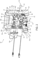
- the latch and lock assembly 30 includes an adjustment assembly 32 and a fixed assembly 34, adjustably connected to each other with an alignment rod 36 and an adjustment tuner 38.
- the adjustment assembly 32 may be installed directly onto the side wall of the treatment chamber 12, while the fixed assembly 34 may be arranged within the boundaries of, and adjustably mounted to, the adjustment assembly 32.
- Various other components of the latch and lock assembly 30 may therefore be mounted to and/or disposed within the boundaries of the fixed assembly 34.
- the adjustment assembly 32 and the fixed assembly 34 are adjustably connected relative to one another by the alignment rod 36 at an upper end and the adjustment tuner 38 at the lower end.
- the alignment rod 36 and the adjustment tuner 38 provide adjustability to the latch and lock assembly 30 to account for any manufacturing tolerances involved in the latch and lock assembly 30 or its integration/installation into the medical device treatment machine 10.
- the alignment rod 36 may be a cylindrical rod that aligns the fixed assembly 34 relative to the adjustment assembly 32 and allows for fast and simple adjustment and movement of the fixed assembly 34 to accommodate for any manufacturing tolerances or desired adjustments for a particular application. As illustrated, the alignment rod 36 passes through at least one wall of the fixed assembly 34 and at least one wall of the adjustment assembly 32 and the adjustment tuner 38 similarly passes through at least one wall of the fixed assembly 34 and at least one wall of the adjustment assembly 32.
- the adjustment tuner 38 may include a threaded bolt 40 having an associated jam nut 42 configured to move the fixed assembly 34 linearly inwards or outwards relative to the adjustment assembly 32 (to the right and left in Figs. 2 - 4 ).
- the alignment rod 36 ensures proper linear alignment when the fixed assembly 34 is moved relative to the adjustment assembly 32.
- the associated jam nut 42 when tightened down after adjustment, prevents rotation of the adjustment tuner 38 and therefore secures the position of the fixed assembly 34 and any of the components within and/or mounted to the fixed assembly 34 relative to the adjustment assembly 32, to prevent any undesired relative movement or adjustment.
- the alignment rod 36 and adjustment tuner 38 may therefore provide both adjustability to and security of the position of the latch and lock assembly 30 throughout its entire service life.
- the latch and lock assembly 30 includes a lever 44 pivotably fixed to the fixed assembly 34 by means of a pivot fastener 46 (or other pivot means including a pivot pin, hinge, or bearing, among others), with an actuation end 48 of the lever 44 on one side of the pivot fastener 46 and a latching end 50 of the lever 44 on the opposite side of the pivot fastener 46.
- the lever 44 is pivotable about its pivot fastener 46 between a latched position, depicted in Figs. 2 and 3 , and an unlatched position, depicted in Fig. 4 .
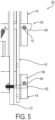
- the lever 44 includes an open-hook recess 52 near or at an end of the latching end 50 of the lever 44 that engages the latch pin 16 of the door 14 when the door 14 is in the closed position and the lever 44 is in the latched position, as shown for example in Fig. 5 .
- the fixed assembly 34 and adjustment assembly 32 include openings through which the lever 44 extends, such that the open hook recess 52 portion of the lever 44 extends to and is therefore engageable with the latch pin 16 of the door 14 when the door 14 is in a closed position.
- the latch and lock assembly 30 may also include a lever biasing member 54 attached to the fixed assembly 34 and lever 44 in a manner to bias the lever 44 toward the latched position.
- the lever biasing member 54 may be a tension spring, as shown, or any other type of biasing means.
- the illustrated latch and lock assembly 30 has a dual actuator configuration, comprising a first actuator 56 and a second actuator 58 that selectively and cooperatively control the position of the lever 44 of the latch and lock assembly 30.
- the first actuator 56 and second actuator 58 may be, for example, solenoids.
- the first actuator 56 and the second actuator 58 are pull-type solenoids, wherein in their unactuated state, their respective actuation rods 57 and 59 are extended due to a spring force exerted by respective springs 57a and 59a of the actuators 56 and 58, and when actuated, their actuation rods 57 and 59 are retracted against the spring force of the springs 57a and 59a, thereby retracting the respective actuation rods 57 and 59 and thus pulling the components to which the actuation rods 57 and 59 are respectively connected.
- push-type solenoids and/or other suitable actuators are contemplated.
- the actuators may be driven electrically and/or pneumatically, for example, and may have any suitable arrangement including for example in-line, as shown, belt driven or gear driven, among others.
- the first actuator 56 selectively moves a locking tab 60 by rotatable connection to the locking tab 60.
- the locking tab 60 has a pivot end 60a at one end, an abutment end 60b at an opposite end, and a coupling aperture 60c therebetween.
- the pivot end 60a is rotatably mounted to the fixed assembly 34 via a pivot fastener 61 (or other pivot means including a pivot pin, hinge, or bearing, among others).
- the actuation rod 57 of the first actuator 56 is rotatably coupled to the locking tab 60 at the coupling aperture 60c via a pin 57b. Extension and retraction of the actuation rod 57 is linear and the coupling aperture 60c may be configured as a vertical slot to compensate for linear movement of the actuation rod 57.
- Extension of the actuation rod 57 translates into clockwise pivotable movement of the locking tab 60 about the pivot fastener 61, which, in turn, urges the abutment end 60b of the locking tab 60 into an abutment position relative to, in the illustrative embodiment below, a first side 62 (lower side, as shown) of the actuation end 48 of the lever 44.
- Retraction of the actuation rod 57 as by energization of the actuator 56 overcoming the force exerted by spring 57a, translates into counterclockwise pivotable movement of the locking tab 60 about the pivot fastener 61, which, in turn, urges the abutment end 60b of the locking tab 60 out of an abutment position relative to, in the illustrative embodiment out from below, the first side 62 of the actuation end 48 of the lever 44.
- the first actuator 56 is thus configured to selectively rotate, or move, the locking tab 60 between a locked position, depicted in Fig. 2 , and an unlocked position, depicted in Figs. 3 and 4 .
- the locking tab 60 in the locked position, is positioned directly next to the lever 44 on the first side 62 of the lever 44, in abutting contact with at least a portion of the lever 44 at the actuation end 48 of the lever 44.
- the abutment end 60b of the locking tab 60 obstructs the path of movement of the actuation end 48 of the lever 44, and thus physically blocks pivotable movement of the lever 44 from the lever's latched position to the lever's unlatched position.
- the abutment end 60b of the locking tab 60 does not obstruct the path of movement of the actuation end 48 of the lever 44, and instead is spaced wholly apart from the lever 44, that is out of the way of the actuation end 48 of the lever 44, thereby allowing pivotable movement of the lever 44 from the lever's latched position to the lever's unlatched position.
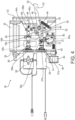
- the second actuator 58 selectively moves a door opening tab 64 by rotatable connection to the door opening tab 64.
- the door opening tab 64 takes the form of a cam, it being appreciated that other forms are possible and contemplated herein.
- the door opening tab 64 has a pivot end 64a at one end, a coupling aperture 64b at an opposite end, and a cam segment 64c laterally offset from the pivot end 64a and the coupling aperture 64b, in the illustrative embodiment laterally offset from a line connecting the pivot end 64a and the coupling aperture 64b.
- the door opening tab 64 has an L-shape configuration with the coupling aperture 64b at the end of one leg of the L, the cam segment 64c at the end of the other leg of the L, and the pivot end 64a at the junction of the legs of the L.
- the pivot end 64a is rotatably mounted to the fixed assembly 34 via a pivot fastener 65 (or other pivot means including a pivot pin, hinge, or bearing, among others).
- the actuation rod 59 of the second actuator 58 is rotatably coupled to the door opening tab 64 at the coupling aperture 64b via a pin 59b.
- Extension and retraction of the actuation rod 59 is linear and the coupling aperture 64b may be configured as a vertical slot to compensate for linear movement of the actuation rod 59.
- Extension of the actuation rod 59 as by spring biasing force, translates into clockwise pivotable movement of the door opening tab 64 about the pivot fastener 65, which, in turn, urges the cam segment 64c of the door opening tab 64 into a first adjacent position relative to, in the illustrative embodiment above, a second side 66 of the actuation end 48 of the lever 44.
- the cam segment 64c of the door opening tab 64 enables the lever 44 to be rotated clockwise about the pivot fastener 46, as by the lever biasing member 54, such that the first side 62 of the actuation end 48 of the lever 44 is in an out of the way position to enable the locking tab 60 to be rotated clockwise to a position in which the abutment end 60b thereof is underneath the first side 62 thereby obstructing the path of movement of the actuation end 48 and locking the lever 44 into the latched position.
- the second side 66 i.e. upper side in the illustrative embodiment, of the actuation end 48 of the lever 44 may abut the cam segment 64c, as shown, although this need not be the case and other embodiments are contemplated.
- the second side 66 of the actuation end 48 of the lever 44 may abut a structure other than the cam segment 64c, so long as the lever 44 is in an out of the way position to enable the locking tab 60 to be rotated to a locked position.
- the second side 66 of the actuation end 48 of the lever 44 may abut the coupling aperture 64b end of the door opening tab 64 or a stop member attached to or formed as part of the fixed assembly 34.
- any portion of the lever 44 not necessarily the second side 66 of the actuation end 48, may abut any other structure of the latch and lock assembly 30 to resist clockwise movement of the lever 44 about the pivot fastener 46 and thus position the lever 44 out of the path of movement of the locking tab 60 so that locking can occur.
- the central portion of the lever surrounding the pivot fastener 46 may be equipped with a radially projecting protuberance that abuts a stop member in of the latch and lock assembly 30 to resist such clockwise movement.
- FIG. 3 shows the latch and lock assembly 30 in an unlocked state, more specifically the abutment end 60b of the locking tab 60 has been moved out of the way from the actuation end 48 of the lever 44, that is, not obstructing the path of movement of the actuation end 48 of the lever 44.
- the cam segment 64c of the door opening tab 64 abuts the second side 66, in the illustrative embodiment the upper side, of the actuation end 48 of the lever 44, and urges the lever 44 counterclockwise about the pivot fastener 46, as by energization force of the actuator 58 overcoming the biasing force of the lever biasing member 54 (and the force exerted by the spring 59a), such that the open hook recess 52 near or at the latching end 50 of the lever 44 is sufficiently raised and out of the way to enable withdrawal of the latch pin 16 of the door 14, that is, to enable opening of the door 14 (automatically or manually).
- the second actuator 58 thus selectively rotates the door opening tab 64 between a first position, depicted in Figs. 2 and 3 , and a second position, depicted in Fig. 4 .
- the rotation of the door opening tab 64 by the second actuator 58 is limited by the position of the locking tab 60, described elsewhere herein.
- the second actuator 58 is configured to rotate the door opening tab 64 from the first position to the second position when the locking tab 60 is in the unlocked position, that is, when the locking tab 60 is not obstructing the path of movement of the actuation end 48 of the lever 44.
- the door opening tab 64 in both the first position and the second position, is positioned next to the actuation end 48 of the lever 44 on the second side 66 of the lever 44. In the first position, the door opening tab 64 may be in abutting contact with at least a portion of the lever 44 at the actuation end 48 of the lever 44, although this need not be the case, as described above. As the door opening tab 64 is rotated from the first position to the second position, the door opening tab 64 abuts at least a portion of the lever 44, for example at the second side 66 of the actuation end 48 thereof, to urge movement of the lever 44 about the pivot fastener 46.
- the cam segment 64c and more generally the door opening tab 64 may have a triangular or oblong shape, such that rotational movement of the door opening tab 64 from the first position to the second position imparts a downward force on the lever 44 (as viewed in Figs. 2-4 ).
- the downward force imparted on the lever 44 by the rotation of the door opening tab 64 overcomes the biasing force of the lever biasing member 54 and therefore pivots the lever 44 from the latched position to the unlatched position and disengages the open hook recess 52 of the lever 44 from the latch pin 16 of the door 14.
- Rotational movement of the door opening tab 64 from the second position to the first position relieves the overcoming downward force on the lever 44, thereby allowing the lever 44 to pivot from the unlatched position to the latched position due to the biasing force of the lever biasing member 54.
- first and second actuators 56, 58 are positioned adjacent one another and lie in the same actuator plane, and their respective rods 57, 59 likewise actuate in the same plane.
- the lever 44, the locking tab 60, and the door opening tab 64 are adjacent one another and lie in the same locking/latching plane.
- the actuator plane is laterally adjacent and parallel to the locking/latching plane, which adds to the accessibility and compactness of the design.
- the pivot fasteners 46, 61, 65, and pivot pins 57b, 59b having their respective pivot axes transverse, perpendicular in the illustrative embodiment, to the respective actuator plane and locking/latching plane.
- the latch and lock assembly 30 may include a door opening tab adjusting block 68 fixed to the fixed assembly 34 and configured to allow adjustment of the position of the door opening tab 64. Adjustment of the position of the door opening tab 64 in the first position may affect the vertical position of the lever 44 for example in embodiments where the door opening tab 64 in the first position is in abutting relation with the lever 44, for example as shown in Figs. 2 and 3 .
- the door opening tab adjusting block 68 may also therefore be configured to allow adjustment of the vertical position of the lever 44 to ensure complete engagement between the open hook recess 52 on the lever 44 and the latch pin 16 of the door 14 when the door 14 is in the closed position and the lever 44 is in the latched position.
- the door opening tab adjusting block 68 includes a tapped block having a screw 68a threaded therein that abuts the door opening tab 64 and when rotated adjusts the position of the door opening tab 64 relative to the lever 44.
- the latch and lock assembly 30 may also include a switch 70 that is electrically connected to a controller of the medical device treatment machine 10 for signaling to the controller when the latch and lock assembly 30 is in a locked or unlocked state.
- the switch 70 may be fixed to the fixed assembly 34 and may include an extending arm 72 that is actuated when the first actuator 56 moves the locking tab 60 from the locked position to the unlocked position.
- the extending arm 72 of the switch 70 is actuated and the switch 70 is configured to send an unlocked signal to the controller, signaling the unlocked state.
- the extending arm 72 of the switch 70 is not actuated and the switch 70 is configured to send a locked signal to the controller, signaling the locked state.
- the controller of the medical device treatment machine 10 actively senses whether and when the latch and lock assembly 30 is in the locked or unlocked state at any given moment.
- the latch and lock assembly 30 may therefore be in any one of: a) a locked/latched state, depicted in Fig. 2 , wherein the latch and lock assembly 30 holds the door 14 in the closed position and does not allow the door 14 to be manually or automatically moved to the open position, b) an unlocked/latched state, depicted in Fig. 3 , wherein the latch and lock assembly 30 holds the door 14 in the closed position and allows the door 14 to be manually moved to the open position for example, by manually opening the door 14 to urge the lever 44 upward (counter clockwise in Figs. 3 and 4 ) against the biasing force of the lever biasing member 54, or c) an unlocked/unlatched state, depicted in Fig.
- latch and lock assembly 30 does not hold the door 14 in the closed position and therefore allows the door 14 to be manually and/or automatically moved to the opened position.
- Which state the latch and lock assembly 30 is in at any given moment is determined by the operation of the first actuator 56 and the second actuator 58 and, therefore, the position of the lever 44 as limited and affected by the position and movement of the locking tab 60 and door opening tab 64.
- the locked/latched state is the default state of the latch and lock assembly 30, where neither the first actuator 56 nor the second actuator 58 are energized. Accordingly, in the event of a power or system shut-off during a treatment cycle of the medical device treatment machine 10, when the door 14 is in a closed position and the latch and lock assembly 30 is in the locked/latched state, the latch and lock assembly 30 will remain in the locked/latched state. In the locked/latched state, the lever 44 of the latch and lock assembly 30 is in the latched position, engaging the latch pin 16 of the door 14.
- the locking tab 60 is in the locked position, obstructing the path of movement of the actuation end 48 of the lever 44, and blocking the lever 44 from becoming unlatched (blocking the lever 44 from moving from the latched position to the unlatched position).
- the door opening tab 64 is in the first position, imparting no force (if not in abutting contact with the lever 44) or a minimal amount of force (if in abutting contact with the lever 44) on the actuation end 48 of the lever 44. Accordingly, the lever 44 is maintained in the latched position by the biasing force of the lever biasing member 54 and the blocking of pivotable movement of the lever 44 by the locking tab 60. Accordingly, in the locked/latched state of Fig. 2 , it is ensured that the door 14 of the medical device treatment machine 10 remains closed and locked and the door 14 is neither manually nor automatically moveable from the closed position to the open position.
- the latch and lock assembly 30 transitions to the unlocked/latched state, depicted in Fig. 3 .
- the locking tab 60 In the unlocked/latched state, the locking tab 60 is in the unlocked position such that the abutment end 60b of the locking tab 60 does not obstruct the path of movement of the actuation end 48 of the lever 44, and instead is spaced wholly apart from the lever 44, as moved by the first actuator 56.
- the locking tab 60 therefore, no longer blocks pivotable movement of the lever 44 from the latched position to the unlatched position.
- the biasing force of the lever biasing member 54 may be overcome by manual force and/or automatic force.
- manual operation of a door handle, pulling the door 14 and thus the latch pin 16 away from the treatment chamber 12, or the like may impart an overcoming force on the lever 44, opposite that of the biasing force of the lever biasing member 54, counterclockwise in the illustrative embodiment, thereby pivoting the lever 44 from the latched position to the unlatched position.
- the door 14 is then free to automatically move to the open position due to for example stored potential energy, gravity, spring or elastic forces or otherwise.
- the hinge biasing member of the hinge 18 may automatically push the door 14 to an open position with its stored potential energy.
- the hinge 18 may be configured to automatically push the door 14 to an open position that is only a few inches open, such that an operator may manually move the door 14 to a more open position.
- the medical device treatment machine 10 may include a forced-entry prevention mechanism 80.
- the forced-entry prevention mechanism 80 is integrated into the medical device treatment machine 10 between the treatment chamber 12 and the door 14 to ensure that an operator cannot use excessive physical force to open the door 14 of the medical device treatment machine 10 when the door 14 is in the closed position and the latch and lock assembly 30 is in a latched and locked state.
- the forced-entry prevention mechanism 80 includes a stop pin 82 fixed to the treatment chamber 12 that projects outward from the treatment chamber 12 into the vicinity of the door 14 of the medical device treatment machine 10.
- the forced-entry prevention mechanism 80 also includes a roller pin 84 fixed to the door 14 in a position aligned for abutting engagement with the stop pin 82 of the treatment chamber 12 when the door 14 is in the closed position.
- the roller pin 84 is positioned for perpendicular alignment with the stop pin 82 when the door 14 is in the closed position.
- the stop pin 82 may be a smooth projection and the roller pin 84 may be a free-rotating cylindrical roller.
- the roller pin 84 may extend from a stop block 86 that is fixed to the door 14.
- the roller pin 84 is positioned to engage the stop pin 82 on a side of the stop pin 82 that is proximal to the latch and lock assembly 30 (the upper side of the stop pin 82 in the Fig. 5 embodiment) such that when the door 14 is in the closed position, the engagement of the roller pin 84 and the stop pin 82 provides an opposing point of contact between the door 14 and the treatment chamber 12. This provides resisting mitigation to downward force that may otherwise overcome the biasing force of the lever biasing member 54 and the locking tab 60 that maintain the latch and lock assembly 30 in the latched and locked state.
- roller pin 84 is configured to slidably abut the stop pin 82 to permit pivotable movement of the door 14 between the closed position and the open position but block a vertical movement of the door 14 in a direction perpendicular to the plane of pivotable movement of the door 14 when the door 14 is in the closed position. This effectively prevents a forced opening of the door 14 when the latch and lock assembly 30 is in a latched and locked state.
- the medical device treatment machine 10 may include a foot-operated automatic door opening mechanism 90.
- the foot-operated automatic door opening mechanism 90 may be activated when the latch and lock assembly 30 is in the unlocked/latched state.
- the operator may either manually transition the latch and lock assembly 30 from the unlocked/latched state to the unlocked/unlatched state to open the door 14, or may initiate automatic transitioning of the latch and lock assembly 30 to the unlocked/unlatched state and automatic opening of the door 14 by use of the foot-operated automatic door opening mechanism 90.
- the foot-operated automatic door opening mechanism 90 may be activated when the latch and lock assembly 30 is in the locked/latched state.
- the operator may use the foot-operated automatic door opening mechanism 90 to both automatically transition the latch and lock assembly 30 from the locked/latched state to the unlocked/latched state and automatically transition the latch and lock assembly 30 from the unlocked/latched state to the unlocked/unlatched state to open the door 14.
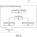
- the foot-operated automatic door opening mechanism 90 includes a sensing apparatus 94 and an indicator apparatus 98.
- the sensing apparatus 94 and the indicator apparatus 98 are configured to interface with each other, and with the latch and lock assembly 30, via a controller 92 that is configured to control the operations, and timing of the operations, of the first actuator 56 and/or the second actuator 58 of the latch and lock assembly 30.
- the sensing apparatus 94 is a proximity sensor configured to detect the presence and removal of a foot of an operator in a sensing zone 96 of the sensing apparatus 94.
- the sensing apparatus 94 may be a pedal or lever disposed in the sensing zone 96 and configured to be engaged and disengaged by a foot of an operator, which engagement and disengagement respectively provide an indication of the presence and removal of the foot of the operator in the sensing zone 96 of the sensing apparatus 94.
- the sensing apparatus 94 may be disposed near a bottom of the medical device treatment machine 10 such that the sensing zone 96 of the sensing apparatus 94, within which the sensing apparatus 94 may detect the presence and removal of the foot of the operator, is near the ground where the medical device treatment machine 10 rests.
- the operator may activate the sensing apparatus 94 by positioning his or her foot in the sensing zone 96 of the sensing apparatus 94, for example by waving the foot within the sensing field of the proximity sensor in one embodiment, or by moving the pedal or lever with the foot in the other embodiment, and may deactivate the sensing apparatus 94 by removing his or her foot from the sensing zone 96 of the sensing apparatus 94 for example, by moving the foot out of the sensing field of the proximity sensor in one embodiment, or by removing the foot from the pedal or lever in the other embodiment.
- the sensing apparatus 94 is therefore configured to detect the presence and removal of the foot of the operator in the sensing zone 96 of the sensing apparatus 94 where the detection is by means of a sensing field of a proximity sensor or engagement and disengagement of a lever or pedal.
- the controller 92 is configured to control the first actuator 56 and/or the second actuator 58 of the latch and lock assembly 30 according to the detection of the presence and removal of the foot of the operator in the sensing zone 96 of the sensing apparatus 94.
- the controller 92 is configured to receive a foot-presence signal from the sensing apparatus 94 when the sensing apparatus 94 detects the presence of the foot of the operator in the sensing zone 96 of the sensing apparatus 94 for example, by detection of the foot in the sensing field of a proximity sensor or by detection of movement of a pedal or lever.
- the controller 92 Upon receipt of the foot-presence signal, the controller 92 is configured to send an activation signal to the indicator apparatus 98 of the medical device treatment machine 10 to activate the indicator apparatus 98.
- the indicator apparatus 98 may include a light indicator that either illuminates or changes color when activated.
- the indicator apparatus 98 may include an audible sound.
- the indicator apparatus 98 may be positioned anywhere on the medical device treatment machine 10 such that it is detectable (visible and/or audible) to the operator.
- the activation of the indicator apparatus 98 provides a visual (or audible) feedback to the operator that the sensing apparatus 94 has been activated and that the operator may remove their foot from the sensing zone 96 of the sensing apparatus 94.
- the controller 92 is configured to receive a foot-removal signal from the sensing apparatus 94 when the sensing apparatus 94 detects the removal of the foot of the operator from the sensing zone 96 of the sensing apparatus 94 for example, by detection that the foot is outside the sensing field of the proximity sensor or by detection that the foot has been removed from the pedal or lever.
- the controller 92 Upon receipt of the foot-removal signal, the controller 92 is then configured to control the operations, and the timing of the operations, of the first actuator 56 and/or the second actuator 58 of the latch and lock assembly 30.
- the controller 92 upon receipt of the foot-removal signal, the controller 92 is configured to send an unlatch signal to the second actuator 58 to rotate the door opening tab 60 to pivot the lever 44 from the latched position to the unlatched position after a predetermined period of time from receipt of the foot removal signal.
- the predetermined period of time may be configured by the controller 92 to be long enough for the operator to move away from the medical device treatment machine 10 before the door 14 is unlatched and automatically moved from the closed position to the open position (or is capable of being manually opened if automatic opening is not provided), so that the operator does not obstruct the opening of the door 14.
- the controller 92 is configured to send an unlock signal, after a first predetermined period of time from receipt of the foot-removal signal, to the first actuator 56 of the latch and lock assembly 30 to move the locking tab 60 from the locked position to the unlocked position.
- the controller 92 is configured to send the unlatch signal to the second actuator 58 to rotate the door opening tab 60 to pivot the lever 44 from the latched position to the unlatched position.
- the first and second predetermined periods of time may be configured by the controller 92 to be long enough for the operator to move away from the medical device treatment machine 10 before the door 14 is unlatched and automatically moved from the closed position to the open position (or is capable of being manually opened if automatic opening is not provided), so that the operator does not obstruct the opening of the door 14.
- the foot-operated automatic door opening mechanism 90 may be in any one of a ready state, an activated state or an automatic-opening state.
- the ready state is the default state of the foot-operated automatic door opening mechanism 90.
- the indicator apparatus 98 is in a first state.
- the first state of the light indicator may either be unilluminated or may be illuminated in a first color.
- the first state of the indicator apparatus 98 indicates to the operator that the sensing apparatus 94 (for example, a proximity sensor or a pedal or lever) is ready for activation.
- the activated state Upon activation of the sensing apparatus 94 by the foot of the operator, the activated state is reached. In the activated state, the indicator apparatus 98 is in a second state. In the embodiment wherein the indicator apparatus 98 is the light indicator, the second state of the light indicator may either be illuminated (where the first state was unilluminated) or may be illuminated in a second color (wherein the first state was illuminated in a first color). The second state of the indicator apparatus 98 indicates to the operator that the sensing apparatus 94 has been activated and that upon subsequent deactivation of the sensing apparatus 94, the latch and lock assembly 30 will be unlatched and the door 14 will be automatically opened after a predetermined period of time or after first and second predetermined periods of time, as the case may be.
- the automatic-opening state Upon deactivation of the sensing apparatus 94 for example by the foot of the operator being out of sensing range of the proximity sensor in one embodiment or removal of the foot from the pedal or lever in the other embodiment, the automatic-opening state, or third state, is reached.
- the controller 92 In the automatic-opening state, in the embodiment in which the foot operated automatic door opening mechanism 90 transitions the latch and lock assembly 30 from the unlocked/latched state to the unlocked/unlatched state, the controller 92 is configured to wait for the respective predetermined period of time, before sending the respective unlatch signal to the second actuator 58 of the latch and lock assembly 30.
- the door 14 Upon unlatching of the latch and lock assembly 30, the door 14 automatically opens (or is capable of being manually opened if automatic opening is not provided), for example in the manner previously described.
- the controller 92 is configured to wait for the respective first and second predetermined periods of time before sending the respective unlock signal and unlatch signal to the first actuator 56 and the second actuator 58, respectively, of the latch and lock assembly 30.
- the door 14 Upon unlocking and unlatching of the latch and lock assembly 30, the door 14 automatically opens (or is capable of being manually opened if automatic opening is not provided), for example in the manner previously described.
- the controller 92 of the latch and lock assembly 30 is generally configured to carry out the overall control of the functions and operations of the first actuator 56, the second actuator 58, the sensing apparatus 94 and/or the indicator apparatus 98.
- the controller 92 may be a central processing unit (CPU), microcontroller, or microprocessor.
- the controller 92 may execute program code stored in a non-transitory computer readable medium, such as random access memory (RAM), a read-only memory (ROM), an erasable programmable read-only memory (EPROM or Flash memory), or any other suitable memory device incorporated into the medical device treatment machine 10, to carry out operation of the first actuator 56, the second actuator 58, the sensing apparatus 94 and/or the indicator apparatus 98.
- RAM random access memory
- ROM read-only memory
- EPROM or Flash memory erasable programmable read-only memory
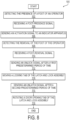
- a method 100 of operating a medical device treatment machine 10 includes, at step 102, detecting, by a sensing apparatus, such as for example a proximity sensor or a pedal or lever disposed on the medical device treatment machine, the presence of a foot of an operator in a sensing zone of the sensing apparatus.
- the method 100 then includes, at step 104, receiving, by a controller of the medical device treatment machine, a foot-presence signal from the sensing apparatus.
- the method 100 includes sending, by the controller, an activation signal to an indicator apparatus of the medical device treatment machine to activate the indicator apparatus.
- the indicator apparatus may be a light indicator and the activation signal may be an illumination signal to illuminate the light indicator.
- the activation signal may be an illumination color-change signal to change an illumination color of the light indicator.
- Other embodiments are also contemplated, as previously described.
- the method 100 further includes detecting, by the sensing apparatus, a removal of the foot of the operator from the sensing zone of the sensing apparatus.
- the method 100 then includes at step 110, receiving, by the controller, a foot-removal signal from the sensing apparatus.
- the method 100 includes sending, at step 116, by the controller, an unlatch signal after a predetermined period of time upon receipt of the foot-removal signal.
- the controller sends the unlatch signal to an actuator, for example the afore described second actuator 58 of the latch and lock assembly.
- the method 100 then includes, at step 118, rotating, by the actuator, a door opening tab of the latch and lock assembly that is in abutting contact with a lever to pivot the lever from a latched position to an unlatched position.
- the method 100 may additionally include automatically moving a door of the medical device treatment machine from a closed position to an open position via a biasing force of a hinge of the door by a hinge biasing member.
- the method 100 may include sending, at step 112, by the controller, an unlock signal after a first predetermined period of time from receipt of the foot removal signal.
- the controller sends the unlock signal to a first actuator of the latch and lock assembly of the medical device treatment machine.
- the method 100 may then include moving, by the first actuator, a locking tab of the latch and lock assembly from a locked position to an unlocked position.
- the sending, at step 116, by the controller of the unlatch signal may occur, therefore, at a second predetermined period of time after receipt of the foot-removal signal and after the first predetermined period of time at which the unlock signal is sent.
- a non-transitory computer-readable medium storing program code.
- the non-transitory computer-readable medium is configured to perform the steps of the method previously described.
Landscapes
- Health & Medical Sciences (AREA)
- Life Sciences & Earth Sciences (AREA)
- Physics & Mathematics (AREA)
- Electromagnetism (AREA)
- General Health & Medical Sciences (AREA)
- Veterinary Medicine (AREA)
- Public Health (AREA)
- Animal Behavior & Ethology (AREA)
- Epidemiology (AREA)
- Engineering & Computer Science (AREA)
- Biomedical Technology (AREA)
- Molecular Biology (AREA)
- Surgery (AREA)
- Medicinal Chemistry (AREA)
- Chemical & Material Sciences (AREA)
- Oral & Maxillofacial Surgery (AREA)
- Medical Informatics (AREA)
- Heart & Thoracic Surgery (AREA)
- Pathology (AREA)
- Nuclear Medicine, Radiotherapy & Molecular Imaging (AREA)
- Mechanical Engineering (AREA)
- Apparatus For Disinfection Or Sterilisation (AREA)
- External Artificial Organs (AREA)
- Surgical Instruments (AREA)
Claims (15)
- Behandlungsmaschine (10) für medizinische Vorrichtungen, umfassend:eine Behandlungskammer (12) zum Waschen, Desinfizieren und/oder Sterilisieren einer medizinischen Vorrichtung,eine Tür (14), die gelenkig an der Behandlungskammer (12) angebracht ist und zwischen einer geöffneten Position zum Freilegen der Behandlungskammer (12) und einer geschlossenen Position zum Abdichten der Behandlungskammer (12) bewegbar ist, wobei die Tür (14) einen Verriegelungsstift (16) an einer ersten Seite (20) der Tür (14) umfasst, undeine Verriegelungs- und Schließbaugruppe (30), die an einer Wand der Behandlungskammer (12) befestigt ist, wobei die Verriegelungs- und Schließbaugruppe (30) Folgendes umfasst:einen Hebel (44), der zwischen einer verriegelten Position und einer entriegelten Position schwenkbar ist, wobei der Hebel (44) in der verriegelten Position mit dem Verriegelungsstift (16) in Eingriff steht, um eine Bewegung der Tür (14) von der geschlossenen Position in die geöffnete Position zu verhindern, und wobei der Hebel (44) in der entriegelten Position den Verriegelungsstift (16) außer Eingriff bringt, um eine Bewegung der Tür (14) von der geschlossenen Position in die geöffnete Position zu ermöglichen,einen ersten Aktuator (56) und eine Verschlusslasche (60), wobei der erste Aktuator (56) mit der Verschlusslasche (60) gekoppelt ist, um die Verschlusslasche (60) selektiv zwischen einer verschlossenen Position und einer aufgeschlossenen Position zu bewegen, wobei die Verschlusslasche (60) in der verschlossenen Position dazu konfiguriert ist, eine schwenkbare Bewegung des Hebels (44) von der verriegelten Position in die entriegelte Position zu blockieren, und wobei die Verschlusslasche (60) in der aufgeschlossenen Position dazu konfiguriert ist, eine schwenkbare Bewegung des Hebels (44) von der verriegelten Position in die entriegelte Position zu ermöglichen, undeinen zweiten Aktuator (58) und eine Türöffnungslasche (64), wobei die Türöffnungslasche (64) ein Nockensegment beinhaltet, und wobei der zweite Aktuator (58) mit der Türöffnungslasche (64) gekoppelt ist, um die Türöffnungslasche (64) selektiv zwischen einer ersten Position und einer zweiten Position zu drehen, wenn die Verschlusslasche (60) in der aufgeschlossenen Position steht, wobei, wenn die Türöffnungslasche (64) in der ersten Position steht, der Hebel (44) in einer verriegelten Position steht, und wobei, wenn die Türöffnungslasche (64) von der ersten Position in die zweite Position gedreht wird, das Nockensegment (64c) der Türöffnungslasche (64) an einer Seite des Hebels (44) anliegt, um den Hebel (44) aus der verriegelten Position in die entriegelte Position zu drängen.
- Behandlungsmaschine (10) für medizinische Vorrichtungen nach Anspruch 1, wobei die Verschlusslasche (60) auf einer ersten Seite (62) des Hebels (44) wirkt und die Türöffnungslasche (64) auf einer der ersten Seite (62) des Hebels (44) gegenüberliegenden zweiten Seite (66) des Hebels (44) wirkt, oder wobei die Verschlusslasche (60) in der verschlossenen Position vorzugsweise an einem Abschnitt des Hebels (44) anliegt, und wobei die Verschlusslasche (60) in der aufgeschlossenen Position vorzugsweise von dem Hebel (44) beabstandet ist.
- Behandlungsmaschine (10) für medizinische Vorrichtungen nach einem der Ansprüche 1-2, ferner umfassend ein Hebelvorspannelement (54), das dazu konfiguriert ist, den Hebel in Richtung der verriegelten Position vorzuspannen, oder wobei das Hebelvorspannelement (54) vorzugsweise eine Feder ist, oder wobei der erste Aktuator (56) und der zweite Aktuator (58) vorzugsweise Zugankermagnete sind, oder vorzugsweise ferner umfassend ein feststehendes Gehäuse, an welchem mindestens eines des Hebels (44), des ersten Aktuators (56), der Verschlusslasche (60), des zweiten Aktuators (58), der Türöffnungslasche (64) und des Hebelvorspannelements (54) montiert sind.
- Behandlungsmaschine (10) für medizinische Vorrichtungen nach Anspruch 3, ferner umfassend ein einstellbares Gehäuse, an welchem das feststehende Gehäuse einstellbar befestigt ist.
- Behandlungsmaschine (10) für medizinische Vorrichtungen nach Anspruch 4, ferner umfassend eine Ausrichtstange (36), die durch eine Wand des feststehenden Gehäuses und eine Wand des einstellbaren Gehäuses hindurchgeht, um das feststehende Gehäuse relativ zu dem einstellbaren Gehäuse auszurichten.
- Behandlungsmaschine (10) für medizinische Vorrichtungen nach einem der Ansprüche 4-5, ferner umfassend einen Einstellstimmer (38), der durch eine Wand des feststehenden Gehäuses und eine Wand des einstellbaren Gehäuses hindurchgeht, wobei der Einstellstimmer (38) einen Gewindebolzen (40) und eine zugeordnete Kontermutter (42) umfasst, welche beim Anziehen eine Bewegung des feststehenden Gehäuses relativ zu dem Einstellgehäuse verhindern.
- Behandlungsmaschine (10) für medizinische Vorrichtungen nach einem der Ansprüche 3-6, ferner umfassend einen Türöffnungslascheneinstellblock (68), der an dem feststehenden Gehäuse montiert ist und eine Schraube (68a) beinhaltet, wobei der Türöffnungslascheneinstellblock (68) dazu konfiguriert ist, die Position der Türöffnungslasche (64) innerhalb des feststehenden Gehäuses relativ zu dem Hebel (44) einzustellen.
- Behandlungsmaschine (10) für medizinische Vorrichtungen nach einem der Ansprüche 1-7, ferner umfassend einen Schalter (70), der dazu konfiguriert ist, zu erfassen, ob und wann die Verschlusslasche (60) in einer verschlossenen Position oder einer aufgeschlossenen Position steht.
- Behandlungsmaschine (10) für medizinische Vorrichtungen nach einem der Ansprüche 1-8, ferner umfassend ein Scharnier (18) an einer zweiten Seite (22) der Tür (14), die der ersten Seite (20) der Tür (14) gegenüberliegt, wobei das Scharnier (18) der Tür (14) vorzugsweise ein Scharnier-Vorspannelement (18a) zum Vorspannen der Tür (14) in Richtung einer geöffneten Position umfasst, um die Tür (14) automatisch von der geschlossenen Position in die geöffnete Position zu bewegen, wenn der Hebel (44) in der entriegelten Position steht.
- Behandlungsmaschine (10) für medizinische Vorrichtungen nach einem der Ansprüche 1-9, ferner umfassend:einen sich von der Kammer (12) erstreckenden Anschlagstift (82), undeinen Anschlagblock (86), der an der Tür (14) befestigt ist, wobei der Anschlagblock (86) einen Rollenstift (84) umfasst, der sich von dem Anschlagblock (86) in einer Richtung erstreckt, die dazu konfiguriert ist, senkrecht zu dem Anschlagstift (82) zu verlaufen, wenn die Tür (14) in einer geschlossenen Position steht,wobei, wenn die Tür (14) in einer geschlossenen Position steht, der Rollenstift (84) gleitend an dem Anschlagstiften (82) anliegt, um eine seitliche Bewegung der Tür (14) zwischen der geschlossenen Position und der geöffneten Position zu ermöglichen und eine vertikale Bewegung der Tür (14) in einer Richtung senkrecht zu der seitlichen Bewegung der Tür (14) zu blockieren.
- Behandlungsmaschine (10) für medizinische Vorrichtungen nach einem der Ansprüche 1-10, ferner umfassend:eine Abtastvorrichtung (94) zum Erfassen eines Vorhandenseins und Entfernens eines Fußes einer Bedienperson in einer Abtastzone (96) der Abtastvorrichtung (94), undeine Steuerung (92) zum Steuern der Vorgänge des zweiten Aktuators (58) gemäß der Erfassung des Vorhandenseins und Entfernens des Fußes der Bedienperson in der Abtastzone (96) der Abtastvorrichtung (94).
- Behandlungsmaschine (10) für medizinische Vorrichtungen nach Anspruch 11, wobei die Steuerung (92) dazu konfiguriert ist:ein Fußanwesenheitssignal von der Abtastvorrichtung (94) zu empfangen, wenn die Abtastvorrichtung (94) das Vorhandensein des Fußes der Bedienperson in der Abtastzone (96) der Abtastvorrichtung (94) erfasst,ein Aktivierungssignal an eine Anzeigevorrichtung (98) an der Behandlungsmaschine (10) für medizinische Vorrichtungen zu senden, um die Anzeigevorrichtung (98) zu aktivieren,ein Fußentfernungssignal von der Abtastvorrichtung (94) zu empfangen, wenn der Fußsensor das Entfernen des Fußes der Bedienperson aus der Abtastzone (96) der Abtastvorrichtung (94) erfasst, undein Entriegelungssignal an den zweiten Aktuator (58) zu senden, um die Türöffnungslasche (60) in Anlagekontakt mit dem Hebel (44) zu drehen, um den Hebel (44) von der verriegelten Position in die entriegelte Position zu schwenken.
- Verfahren zum Betreiben einer Behandlungsmaschine (10) für medizinische Vorrichtungen nach einem der Ansprüche 1-12, wobei das Verfahren die folgenden Schritte umfasst:
Drehen, durch den zweiten Aktuator (58), der Türöffnungslasche (60) der Verriegelungs- und Schließbaugruppe (30), die in Anlagekontakt mit dem Hebel (44) steht, um den Hebel (44) von der verriegelten Position in die entriegelte Position zu schwenken. - Verfahren nach Anspruch 13, ferner umfassend die folgenden Schritte:Erfassen, durch eine an der Behandlungsmaschine (10) für medizinische Vorrichtungen angeordnete Abtastvorrichtung (94), des Vorhandenseins eines Fußes einer Bedienperson in einer Abtastzone (96) der Abtastvorrichtung (94),Empfangen, durch eine Steuerung (92) der Behandlungsmaschine (10) für medizinische Vorrichtungen, eines Fußanwesenheitssignals von der Abtastvorrichtung (94),Senden, durch die Steuerung (92), eines Aktivierungssignals an eine Anzeigevorrichtung (98) an der Behandlungsmaschine (10) für medizinische Vorrichtungen, um die Anzeigevorrichtung (98) zu aktivieren,Erfassen, durch die Abtastvorrichtung (94), des Entfernens des Fußes der Bedienperson aus der Abtastzone (96) der Abtastvorrichtung (94), undEmpfangen, durch die Steuerung (92), eines Fußentfernungssignals von der Abtastvorrichtung (94),Senden, durch die Steuerung (92), eines Entriegelungssignals an den ersten Aktuator (56) der Verriegelungs- und Schließbaugruppe (30) der Behandlungsmaschine (10) für medizinische Vorrichtungen.
- Verfahren nach Anspruch 14, wobei das Entriegelungssignal in einer vorbestimmten Zeitspanne nach dem Empfang des Fußentfernungssignals an den Aktuator gesendet wird, oder vorzugsweise ferner umfassend:
automatisches Bewegen der Tür (14) der Behandlungsmaschine (10) für medizinische Vorrichtungen aus der geschlossenen Position in die geöffnete Position über eine Vorspannkraft eines Scharniers (18) der Tür (14) durch ein Scharnier-Vorspannelement (18a).
Priority Applications (1)
| Application Number | Priority Date | Filing Date | Title |
|---|---|---|---|
| EP24200342.4A EP4455430B1 (de) | 2019-09-12 | 2020-08-31 | Türschloss, schliess- und öffnungsmechanismus für ein medizinproduktbehandlungssystem |
Applications Claiming Priority (2)
| Application Number | Priority Date | Filing Date | Title |
|---|---|---|---|
| US201962899192P | 2019-09-12 | 2019-09-12 | |
| PCT/US2020/048705 WO2021050309A2 (en) | 2019-09-12 | 2020-08-31 | Door latch, lock and open mechanism for medical device treatment system |
Related Child Applications (2)
| Application Number | Title | Priority Date | Filing Date |
|---|---|---|---|
| EP24200342.4A Division-Into EP4455430B1 (de) | 2019-09-12 | 2020-08-31 | Türschloss, schliess- und öffnungsmechanismus für ein medizinproduktbehandlungssystem |
| EP24200342.4A Division EP4455430B1 (de) | 2019-09-12 | 2020-08-31 | Türschloss, schliess- und öffnungsmechanismus für ein medizinproduktbehandlungssystem |
Publications (2)
| Publication Number | Publication Date |
|---|---|
| EP4028617A2 EP4028617A2 (de) | 2022-07-20 |
| EP4028617B1 true EP4028617B1 (de) | 2024-10-30 |
Family
ID=72470613
Family Applications (2)
| Application Number | Title | Priority Date | Filing Date |
|---|---|---|---|
| EP20771409.8A Active EP4028617B1 (de) | 2019-09-12 | 2020-08-31 | Türschloss, schliess- und öffnungsmechanismus für ein medizinproduktbehandlungssystem |
| EP24200342.4A Active EP4455430B1 (de) | 2019-09-12 | 2020-08-31 | Türschloss, schliess- und öffnungsmechanismus für ein medizinproduktbehandlungssystem |
Family Applications After (1)
| Application Number | Title | Priority Date | Filing Date |
|---|---|---|---|
| EP24200342.4A Active EP4455430B1 (de) | 2019-09-12 | 2020-08-31 | Türschloss, schliess- und öffnungsmechanismus für ein medizinproduktbehandlungssystem |
Country Status (7)
| Country | Link |
|---|---|
| US (2) | US11980697B2 (de) |
| EP (2) | EP4028617B1 (de) |
| AU (1) | AU2020347095B2 (de) |
| CA (1) | CA3150989A1 (de) |
| ES (1) | ES3000682T3 (de) |
| MX (1) | MX2022002945A (de) |
| WO (1) | WO2021050309A2 (de) |
Families Citing this family (3)
| Publication number | Priority date | Publication date | Assignee | Title |
|---|---|---|---|---|
| EP3611316A1 (de) * | 2018-08-13 | 2020-02-19 | Montajes Electronicos Dorcas, S.L. | Sperrvorrichtung |
| CN115711075B (zh) * | 2022-10-26 | 2025-07-08 | 张家港市环宇制药设备有限公司 | 灭菌柜自动开关门装置 |
| WO2025025105A1 (zh) * | 2023-07-31 | 2025-02-06 | 深圳市理邦精密仪器股份有限公司 | 一种医疗检测设备 |
Citations (1)
| Publication number | Priority date | Publication date | Assignee | Title |
|---|---|---|---|---|
| EP1405967A1 (de) * | 2002-10-01 | 2004-04-07 | M.O.COM. S.r.L. | Verschlussvorrichtung insbesondere für eine Dampfsterilisierungmaschine |
Family Cites Families (22)
| Publication number | Priority date | Publication date | Assignee | Title |
|---|---|---|---|---|
| US971423A (en) | 1910-05-06 | 1910-09-27 | Frank Walters | Lock. |
| US3751088A (en) * | 1971-05-24 | 1973-08-07 | Schlage Lock Co | Electromagnetic lock |
| US3767242A (en) | 1971-10-29 | 1973-10-23 | Lectron Products | Solenoid operated door lock |
| US3874117A (en) | 1973-09-28 | 1975-04-01 | R H Boehm Company Inc | Electric door opener |
| US4434635A (en) * | 1980-03-11 | 1984-03-06 | F.A.M.A. Di Sandra Borgato & C., S.N.C. | Manually and electrically commanded automatic hooklock |
| NO176933C (no) | 1989-01-24 | 1995-06-21 | Siegenia Frank Kg | Vindu eller dör med ei vippbar og svingbar vindusramme eller dörblad |
| US5223229A (en) | 1990-07-19 | 1993-06-29 | Midmark Corporation | Sterilizing apparatus having automatically actuated door |
| GB9120512D0 (en) | 1991-09-26 | 1991-11-06 | Newtronics Sa | Locks |
| US5263596A (en) | 1991-12-02 | 1993-11-23 | Williams David R | Medication dispenser station sub-assembly |
| US5460294A (en) | 1994-05-12 | 1995-10-24 | Pyxis Corporation | Single dose pharmaceutical dispenser subassembly |
| US5879036A (en) | 1996-09-19 | 1999-03-09 | Moline; Steven S. | Door interlock for an appliance such as a washer |
| US20030222548A1 (en) | 2002-05-31 | 2003-12-04 | Richardson William R. | Storage device for health care facility |
| US6967587B2 (en) | 2003-09-22 | 2005-11-22 | Sanidoor, Llc | Hands-free door opener and method |
| US7038409B1 (en) | 2005-03-16 | 2006-05-02 | Wayne-Dalton Corp. | Operating system utilizing a delay-open function for a motorized barrier operator |
| JP5467911B2 (ja) * | 2010-03-29 | 2014-04-09 | 富士フイルム株式会社 | 洗浄消毒装置及び洗浄消毒装置の制御方法 |
| GB2495290A (en) | 2011-10-04 | 2013-04-10 | Nissan Motor Mfg Uk Ltd | Apparatus and method for opening a closure of a vehicle |
| US20130219793A1 (en) | 2012-02-23 | 2013-08-29 | Master Lock Company Llc | Door locking assemblies and arrangements |
| US20140265805A1 (en) | 2013-03-15 | 2014-09-18 | Whirlpool Corporation | Appliance with automatic door opener |
| DE102013015119A1 (de) | 2013-09-12 | 2015-03-12 | Brose Fahrzeugteile Gmbh & Co. Kommanditgesellschaft, Hallstadt | Stellvorrichtung zur Verstellung eines zwischen einer Schließstellung und einer Offenstellung verstellbaren Fahrzeugteils |
| US9474432B2 (en) | 2013-12-11 | 2016-10-25 | Whirlpool Corporation | Household appliance and method of opening the same |
| CN106121384B (zh) * | 2016-08-22 | 2018-05-25 | 安徽信息工程学院 | 平开电动自动门的防意外机械卡锁装置及其开关门方法 |
| CN208710104U (zh) * | 2017-12-28 | 2019-04-09 | 广州吉好医疗科技有限公司 | 带有内镜接头脱落感应装置的多槽内镜清洗消毒机 |
-
2020
- 2020-08-31 EP EP20771409.8A patent/EP4028617B1/de active Active
- 2020-08-31 MX MX2022002945A patent/MX2022002945A/es unknown
- 2020-08-31 EP EP24200342.4A patent/EP4455430B1/de active Active
- 2020-08-31 US US17/007,289 patent/US11980697B2/en active Active
- 2020-08-31 ES ES20771409T patent/ES3000682T3/es active Active
- 2020-08-31 CA CA3150989A patent/CA3150989A1/en active Pending
- 2020-08-31 AU AU2020347095A patent/AU2020347095B2/en active Active
- 2020-08-31 WO PCT/US2020/048705 patent/WO2021050309A2/en not_active Ceased
-
2024
- 2024-04-10 US US18/631,411 patent/US20240252706A1/en active Pending
Patent Citations (1)
| Publication number | Priority date | Publication date | Assignee | Title |
|---|---|---|---|---|
| EP1405967A1 (de) * | 2002-10-01 | 2004-04-07 | M.O.COM. S.r.L. | Verschlussvorrichtung insbesondere für eine Dampfsterilisierungmaschine |
Also Published As
| Publication number | Publication date |
|---|---|
| WO2021050309A3 (en) | 2021-04-15 |
| EP4455430A3 (de) | 2025-01-29 |
| MX2022002945A (es) | 2022-06-14 |
| ES3000682T3 (en) | 2025-03-03 |
| EP4455430A2 (de) | 2024-10-30 |
| US11980697B2 (en) | 2024-05-14 |
| US20240252706A1 (en) | 2024-08-01 |
| EP4028617A2 (de) | 2022-07-20 |
| AU2020347095B2 (en) | 2023-11-23 |
| AU2020347095A1 (en) | 2022-03-31 |
| EP4455430B1 (de) | 2025-11-12 |
| CA3150989A1 (en) | 2021-03-18 |
| US20210079711A1 (en) | 2021-03-18 |
| WO2021050309A2 (en) | 2021-03-18 |
Similar Documents
| Publication | Publication Date | Title |
|---|---|---|
| US20240252706A1 (en) | Door latch, lock and open mechanism for medical device treatment system | |
| US8814233B2 (en) | Safety switch for generating a system enable signal depending on the position of a movable guard door | |
| US9663981B2 (en) | Vehicle closure member power actuator control | |
| KR101396927B1 (ko) | 세탁기용 도어락 장치 | |
| US9567782B2 (en) | Lower lock of the passive door blade of a double door | |
| US10988959B1 (en) | Rim strike assembly and methods of use | |
| US20120248796A1 (en) | Door lock device | |
| JP2016510382A (ja) | 防護扉監視システム | |
| JP4832379B2 (ja) | 高圧蒸気滅菌器 | |
| CA2492316A1 (en) | Door locking mechanism | |
| US6391258B1 (en) | Pressure vessel having electromechanical latching mechanism | |
| EP3108080A1 (de) | Werkzeugbetriebene kanalsperre | |
| CA2401162C (en) | Closing sheet for escape doors | |
| KR102691524B1 (ko) | 푸시-푸시 도어 래치 및 이를 구비한 가전기기 | |
| US20020195828A1 (en) | Closure device | |
| EP4329829A1 (de) | Türverriegelungsmechanismus für einen sterilisator | |
| WO2017173253A1 (en) | Exit device dogging using a combination lock | |
| EA017821B1 (ru) | Замок для усиленных дверей и тому подобного | |
| CA3106220C (en) | Rim strike assembly and methods of use | |
| EP1669530B1 (de) | Verriegelungsvorrichtung für Türen von industriellen Maschinen | |
| EP3372767B1 (de) | Sicherheitsvorrichtung zum verschliessen von inspektionstüren | |
| EP0652343A1 (de) | Durch Panikgriff zu betätigende Schlossanordnung | |
| CN119640542A (zh) | 一种洗涤设备自动开关门控制方法 | |
| JP2012172327A (ja) | 窓用錠装置 |
Legal Events
| Date | Code | Title | Description |
|---|---|---|---|
| STAA | Information on the status of an ep patent application or granted ep patent |
Free format text: STATUS: UNKNOWN |
|
| STAA | Information on the status of an ep patent application or granted ep patent |
Free format text: STATUS: THE INTERNATIONAL PUBLICATION HAS BEEN MADE |
|
| PUAI | Public reference made under article 153(3) epc to a published international application that has entered the european phase |
Free format text: ORIGINAL CODE: 0009012 |
|
| STAA | Information on the status of an ep patent application or granted ep patent |
Free format text: STATUS: REQUEST FOR EXAMINATION WAS MADE |
|
| 17P | Request for examination filed |
Effective date: 20220317 |
|
| AK | Designated contracting states |
Kind code of ref document: A2 Designated state(s): AL AT BE BG CH CY CZ DE DK EE ES FI FR GB GR HR HU IE IS IT LI LT LU LV MC MK MT NL NO PL PT RO RS SE SI SK SM TR |
|
| DAV | Request for validation of the european patent (deleted) | ||
| DAX | Request for extension of the european patent (deleted) | ||
| STAA | Information on the status of an ep patent application or granted ep patent |
Free format text: STATUS: EXAMINATION IS IN PROGRESS |
|
| 17Q | First examination report despatched |
Effective date: 20230414 |
|
| P01 | Opt-out of the competence of the unified patent court (upc) registered |
Effective date: 20230513 |
|
| GRAP | Despatch of communication of intention to grant a patent |
Free format text: ORIGINAL CODE: EPIDOSNIGR1 |
|
| STAA | Information on the status of an ep patent application or granted ep patent |
Free format text: STATUS: GRANT OF PATENT IS INTENDED |
|
| INTG | Intention to grant announced |
Effective date: 20240716 |
|
| GRAS | Grant fee paid |
Free format text: ORIGINAL CODE: EPIDOSNIGR3 |
|
| GRAA | (expected) grant |
Free format text: ORIGINAL CODE: 0009210 |
|
| STAA | Information on the status of an ep patent application or granted ep patent |
Free format text: STATUS: THE PATENT HAS BEEN GRANTED |
|
| AK | Designated contracting states |
Kind code of ref document: B1 Designated state(s): AL AT BE BG CH CY CZ DE DK EE ES FI FR GB GR HR HU IE IS IT LI LT LU LV MC MK MT NL NO PL PT RO RS SE SI SK SM TR |
|
| REG | Reference to a national code |
Ref country code: GB Ref legal event code: FG4D |
|
| REG | Reference to a national code |
Ref country code: CH Ref legal event code: EP |
|
| REG | Reference to a national code |
Ref country code: DE Ref legal event code: R096 Ref document number: 602020040358 Country of ref document: DE |
|
| REG | Reference to a national code |
Ref country code: IE Ref legal event code: FG4D |
|
| REG | Reference to a national code |
Ref country code: LT Ref legal event code: MG9D |
|
| REG | Reference to a national code |
Ref country code: ES Ref legal event code: FG2A Ref document number: 3000682 Country of ref document: ES Kind code of ref document: T3 Effective date: 20250303 |
|
| REG | Reference to a national code |
Ref country code: NL Ref legal event code: MP Effective date: 20241030 |
|
| PG25 | Lapsed in a contracting state [announced via postgrant information from national office to epo] |
Ref country code: PT Free format text: LAPSE BECAUSE OF FAILURE TO SUBMIT A TRANSLATION OF THE DESCRIPTION OR TO PAY THE FEE WITHIN THE PRESCRIBED TIME-LIMIT Effective date: 20250228 Ref country code: HR Free format text: LAPSE BECAUSE OF FAILURE TO SUBMIT A TRANSLATION OF THE DESCRIPTION OR TO PAY THE FEE WITHIN THE PRESCRIBED TIME-LIMIT Effective date: 20241030 Ref country code: IS Free format text: LAPSE BECAUSE OF FAILURE TO SUBMIT A TRANSLATION OF THE DESCRIPTION OR TO PAY THE FEE WITHIN THE PRESCRIBED TIME-LIMIT Effective date: 20250228 |
|
| PG25 | Lapsed in a contracting state [announced via postgrant information from national office to epo] |
Ref country code: FI Free format text: LAPSE BECAUSE OF FAILURE TO SUBMIT A TRANSLATION OF THE DESCRIPTION OR TO PAY THE FEE WITHIN THE PRESCRIBED TIME-LIMIT Effective date: 20241030 Ref country code: NL Free format text: LAPSE BECAUSE OF FAILURE TO SUBMIT A TRANSLATION OF THE DESCRIPTION OR TO PAY THE FEE WITHIN THE PRESCRIBED TIME-LIMIT Effective date: 20241030 |
|
| REG | Reference to a national code |
Ref country code: AT Ref legal event code: MK05 Ref document number: 1737018 Country of ref document: AT Kind code of ref document: T Effective date: 20241030 |
|
| PG25 | Lapsed in a contracting state [announced via postgrant information from national office to epo] |
Ref country code: BG Free format text: LAPSE BECAUSE OF FAILURE TO SUBMIT A TRANSLATION OF THE DESCRIPTION OR TO PAY THE FEE WITHIN THE PRESCRIBED TIME-LIMIT Effective date: 20241030 |
|
| PG25 | Lapsed in a contracting state [announced via postgrant information from national office to epo] |
Ref country code: NO Free format text: LAPSE BECAUSE OF FAILURE TO SUBMIT A TRANSLATION OF THE DESCRIPTION OR TO PAY THE FEE WITHIN THE PRESCRIBED TIME-LIMIT Effective date: 20250130 |
|
| PG25 | Lapsed in a contracting state [announced via postgrant information from national office to epo] |
Ref country code: LV Free format text: LAPSE BECAUSE OF FAILURE TO SUBMIT A TRANSLATION OF THE DESCRIPTION OR TO PAY THE FEE WITHIN THE PRESCRIBED TIME-LIMIT Effective date: 20241030 Ref country code: GR Free format text: LAPSE BECAUSE OF FAILURE TO SUBMIT A TRANSLATION OF THE DESCRIPTION OR TO PAY THE FEE WITHIN THE PRESCRIBED TIME-LIMIT Effective date: 20250131 Ref country code: AT Free format text: LAPSE BECAUSE OF FAILURE TO SUBMIT A TRANSLATION OF THE DESCRIPTION OR TO PAY THE FEE WITHIN THE PRESCRIBED TIME-LIMIT Effective date: 20241030 |
|
| PG25 | Lapsed in a contracting state [announced via postgrant information from national office to epo] |
Ref country code: PL Free format text: LAPSE BECAUSE OF FAILURE TO SUBMIT A TRANSLATION OF THE DESCRIPTION OR TO PAY THE FEE WITHIN THE PRESCRIBED TIME-LIMIT Effective date: 20241030 |
|
| PG25 | Lapsed in a contracting state [announced via postgrant information from national office to epo] |
Ref country code: RS Free format text: LAPSE BECAUSE OF FAILURE TO SUBMIT A TRANSLATION OF THE DESCRIPTION OR TO PAY THE FEE WITHIN THE PRESCRIBED TIME-LIMIT Effective date: 20250130 |
|
| PG25 | Lapsed in a contracting state [announced via postgrant information from national office to epo] |
Ref country code: SM Free format text: LAPSE BECAUSE OF FAILURE TO SUBMIT A TRANSLATION OF THE DESCRIPTION OR TO PAY THE FEE WITHIN THE PRESCRIBED TIME-LIMIT Effective date: 20241030 |
|
| PG25 | Lapsed in a contracting state [announced via postgrant information from national office to epo] |
Ref country code: DK Free format text: LAPSE BECAUSE OF FAILURE TO SUBMIT A TRANSLATION OF THE DESCRIPTION OR TO PAY THE FEE WITHIN THE PRESCRIBED TIME-LIMIT Effective date: 20241030 |
|
| PG25 | Lapsed in a contracting state [announced via postgrant information from national office to epo] |
Ref country code: EE Free format text: LAPSE BECAUSE OF FAILURE TO SUBMIT A TRANSLATION OF THE DESCRIPTION OR TO PAY THE FEE WITHIN THE PRESCRIBED TIME-LIMIT Effective date: 20241030 |
|
| PG25 | Lapsed in a contracting state [announced via postgrant information from national office to epo] |
Ref country code: RO Free format text: LAPSE BECAUSE OF FAILURE TO SUBMIT A TRANSLATION OF THE DESCRIPTION OR TO PAY THE FEE WITHIN THE PRESCRIBED TIME-LIMIT Effective date: 20241030 |
|
| PG25 | Lapsed in a contracting state [announced via postgrant information from national office to epo] |
Ref country code: SK Free format text: LAPSE BECAUSE OF FAILURE TO SUBMIT A TRANSLATION OF THE DESCRIPTION OR TO PAY THE FEE WITHIN THE PRESCRIBED TIME-LIMIT Effective date: 20241030 |
|
| PG25 | Lapsed in a contracting state [announced via postgrant information from national office to epo] |
Ref country code: CZ Free format text: LAPSE BECAUSE OF FAILURE TO SUBMIT A TRANSLATION OF THE DESCRIPTION OR TO PAY THE FEE WITHIN THE PRESCRIBED TIME-LIMIT Effective date: 20241030 |
|
| REG | Reference to a national code |
Ref country code: DE Ref legal event code: R097 Ref document number: 602020040358 Country of ref document: DE |
|
| PLBE | No opposition filed within time limit |
Free format text: ORIGINAL CODE: 0009261 |
|
| STAA | Information on the status of an ep patent application or granted ep patent |
Free format text: STATUS: NO OPPOSITION FILED WITHIN TIME LIMIT |
|
| PG25 | Lapsed in a contracting state [announced via postgrant information from national office to epo] |
Ref country code: SE Free format text: LAPSE BECAUSE OF FAILURE TO SUBMIT A TRANSLATION OF THE DESCRIPTION OR TO PAY THE FEE WITHIN THE PRESCRIBED TIME-LIMIT Effective date: 20241030 |
|
| 26N | No opposition filed |
Effective date: 20250731 |
|
| PGFP | Annual fee paid to national office [announced via postgrant information from national office to epo] |
Ref country code: ES Payment date: 20250901 Year of fee payment: 6 |
|
| PGFP | Annual fee paid to national office [announced via postgrant information from national office to epo] |
Ref country code: DE Payment date: 20250827 Year of fee payment: 6 |
|
| PGFP | Annual fee paid to national office [announced via postgrant information from national office to epo] |
Ref country code: IT Payment date: 20250820 Year of fee payment: 6 |
|
| PGFP | Annual fee paid to national office [announced via postgrant information from national office to epo] |
Ref country code: GB Payment date: 20250827 Year of fee payment: 6 |
|
| PGFP | Annual fee paid to national office [announced via postgrant information from national office to epo] |
Ref country code: FR Payment date: 20250825 Year of fee payment: 6 |