EP4027770B1 - Têtes de récolte ayant des capteurs de hauteur, machines agricoles portant de telles têtes et procédés associés - Google Patents
Têtes de récolte ayant des capteurs de hauteur, machines agricoles portant de telles têtes et procédés associés Download PDFInfo
- Publication number
- EP4027770B1 EP4027770B1 EP20719638.7A EP20719638A EP4027770B1 EP 4027770 B1 EP4027770 B1 EP 4027770B1 EP 20719638 A EP20719638 A EP 20719638A EP 4027770 B1 EP4027770 B1 EP 4027770B1
- Authority
- EP
- European Patent Office
- Prior art keywords
- harvesting
- header
- tool
- soil surface
- crop
- Prior art date
- Legal status (The legal status is an assumption and is not a legal conclusion. Google has not performed a legal analysis and makes no representation as to the accuracy of the status listed.)
- Active
Links
Images


Classifications
-
- A—HUMAN NECESSITIES
- A01—AGRICULTURE; FORESTRY; ANIMAL HUSBANDRY; HUNTING; TRAPPING; FISHING
- A01D—HARVESTING; MOWING
- A01D41/00—Combines, i.e. harvesters or mowers combined with threshing devices
- A01D41/12—Details of combines
- A01D41/14—Mowing tables
- A01D41/141—Automatic header control
-
- A—HUMAN NECESSITIES
- A01—AGRICULTURE; FORESTRY; ANIMAL HUSBANDRY; HUNTING; TRAPPING; FISHING
- A01D—HARVESTING; MOWING
- A01D41/00—Combines, i.e. harvesters or mowers combined with threshing devices
- A01D41/12—Details of combines
- A01D41/127—Control or measuring arrangements specially adapted for combines
Definitions
- This disclosure relates to harvesting headers for use with self-propelled crop-harvesting machines, and particularly to headers having sensors.
- Self-propelled agricultural harvesters include, by way of example, combine harvesters, windrowers, and forage harvesters, all of which typically include a frame or chassis, an operator cab, an engine, and ground-engaging wheels or tracks.
- a cutting or pick-up header is often carried by the harvester, the header typically being considerably wider than the harvester and mounted to the front side of a feederhouse.
- Crop material collected by the header is conveyed into the feederhouse before being conveyed in a generally rearward direction to crop-processing apparatus.
- the processing apparatus serves to thresh the crop material and separate grain therefrom, whereas, in the case of a forage harvester or windrower, the crop material is typically passed through conditioning rollers.
- Headers typically include a pair of crop dividers on opposite ends of a crop-gathering mechanism.
- the dividers divide and lift the crop, and guide it inwardly toward the crop-gathering mechanism, where it may be harvested by one or more harvesting tools, such as a set of oscillating blades.
- Dividers may carry divider points, which may extend forward or upward from the front of the divider.
- Harvesting headers may contact the ground in certain terrain ( e.g., hilly, rough, etc.). Contact between the header and the ground may cause damage to the header and/or the ground.
- US-4,141,200 discloses a tomato harvester with an automatic header adjustment system having a tined control wheel mounted forward of a leading edge.
- a control mechanism is actuated by relative vertical movements of the control wheel for raising and lowering the leading edge of the elevator in response to ground surface irregularities sensed by the wheel.
- a harvesting header for use with a crop-harvesting machine includes a header frame structured to be coupled to a front of the crop-harvesting machine, at least one harvesting tool carried by the header frame and configured to cut crop material, a rotatable arm coupled to the header frame at a pivot point and extending forward of the at least one harvesting tool when the harvesting header is used to cut crop material, a wheel coupled to the rotatable arm and configured to roll along a soil surface leading the at least one harvesting tool when the harvesting header is used to cut crop material in an agricultural field, and a sensor coupled to the header frame at the pivot point and configured to provide a signal to the crop-harvesting machine, the signal correlated to the angle of the rotatable arm with respect to the header frame.
- An agricultural harvester includes a chassis, a feederhouse carried by the chassis, a processing system carried by the chassis and structured to receive crop material from the feederhouse, a grain bin carried by the chassis and structured to receive processed grain from the processing system, a harvesting header coupled to the feederhouse and configured to cut grain, and a control system configured to adjust a position of the harvesting header relative to the agricultural harvester.
- a method of operating an agricultural harvester includes propelling the agricultural harvester through an agricultural field, sensing a contour of a soil surface leading at least one harvesting tool carried by a harvesting header, and adjusting a height of the harvesting header based on the sensed contour.
- the terms “comprising,” “including,” “containing,” “characterized by,” and grammatical equivalents thereof are inclusive or open-ended terms that do not exclude additional, unrecited elements or method steps, but also include the more restrictive terms “consisting of” and “consisting essentially of” and grammatical equivalents thereof.
- the term “may” with respect to a material, structure, feature, or method act indicates that such is contemplated for use in implementation of an embodiment of the disclosure, and such term is used in preference to the more restrictive term “is” so as to avoid any implication that other, compatible materials, structures, features, and methods usable in combination therewith should or must be excluded.
- the term “configured” refers to a size, shape, material composition, and arrangement of one or more of at least one structure and at least one apparatus facilitating operation of one or more of the structure and the apparatus in a predetermined way.
- spatially relative terms such as “beneath,” “below,” “lower,” “bottom,” “above,” “upper,” “top,” “front,” “rear,” “left,” “right,” and the like, may be used for ease of description to describe one element's or feature's relationship to another element(s) or feature(s) as illustrated in the figures. Unless otherwise specified, the spatially relative terms are intended to encompass different orientations of the materials in addition to the orientation depicted in the figures.
- the term "substantially" in reference to a given parameter, property, or condition means and includes to a degree that one of ordinary skill in the art would understand that the given parameter, property, or condition is met with a degree of variance, such as within acceptable manufacturing tolerances.
- the parameter, property, or condition may be at least 90.0% met, at least 95.0% met, at least 99.0% met, or even at least 99.9% met.
- the term "about” used in reference to a given parameter is inclusive of the stated value and has the meaning dictated by the context ( e.g., it includes the degree of error associated with measurement of the given parameter).
- FIG. 1 illustrates an example agricultural harvester embodied as a combine harvester 100.
- the example combine harvester 100 is merely illustrative, and other machines and/or implements with like functionality may deploy certain embodiments disclosed herein, such as windrowers, forage harvesters, etc.
- the example combine harvester 100 is shown in FIG. 1 without a header attached, and includes a feederhouse 102 carried by a chassis 104 supported by wheels 106.
- An operator cab 108 is mounted to the chassis 104.
- Hydraulic cylinders 110 are shown affixed to the underside of the feederhouse 102 on one end and to the chassis 104 on the other end.
- the feederhouse 102 may move ( e.g., up and down, pitch, tilt, etc.) based on actuation of the hydraulic cylinders 110, which causes a detachably coupled header to also be raised, lowered, pitched, and/or tilted.
- a rotating shaft 112 may be configured to provide mechanical power to a header during operation of the combine harvester 100.
- the rotating shaft 112 may be configured to operate at various speeds, as described in, for example, U.S. Patent 9,434,252, "Power Takeoff Drive System for a Vehicle," issued September 6, 2016 .
- the combine harvester 100 cuts crop materials (e.g., using the header), and the cut crop materials are delivered to the front end of the feederhouse assembly 200. Such crop materials are moved upwardly and rearwardly within and beyond the feederhouse 102 ( e.g., by a conveyer) until reaching a processing system 114 that includes a thresher rotor.
- the thresher rotor may comprise a single, transverse rotor, such as that found in a Gleaner ® Super Series Combine by AGCO.
- Other designs may be used, such as axial-based, twin rotor, or hybrid designs.
- the thresher rotor processes the crop materials in known manner and passes a portion of the crop material (e.g., heavier chaff, corn stalks, etc.) toward the rear of the combine harvester 100 and another portion (e.g., grain and possibly light chaff) through a cleaning process.
- the crop materials undergo threshing and separating operations.
- the crop materials are threshed and separated by the thresher rotor operating in cooperation with well-known foraminous processing members in the form of threshing concave assemblies and separator grate assemblies, with the grain (and possibly light chaff) escaping through the concave assemblies and the grate assemblies and to a cleaning system beneath the processor to facilitate the cleaning of the heavier crop material.
- Bulkier stalk and leaf materials are generally retained by the concave assemblies and the grate assemblies and are discharged out from the processing system 114 and ultimately out of the rear of the combine harvester 100.
- the cleaned grain that drops to the bottom of the cleaning system is delivered by a conveying mechanism that transports the grain to an elevator, which conveys the grain to a grain bin 116 located at the top of the combine harvester 100. Any remaining chaff and partially or unthreshed grain is recirculated through the processing system 114 via a tailings return conveying mechanism.
- the processing system 114 may include conditioning rollers rather than separation devices.
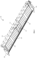
- FIG. 2 is a simplified view of a header 200 that may be attached to the feederhouse 102 of the combine harvester 100 ( FIG. 1 ) and used to harvest a crop.
- the header 200 includes a header frame 202, at least one harvesting tool 204, and dividers 206 at either end of the header 200.
- the harvesting tool 204 is depicted as an oscillating blade, but may be any other tool used for harvesting crops that come into contact with the harvesting tool 204.
- the dividers 206 may serve to define boundaries between crop material being harvested and standing crop (typically, material to be harvested in a subsequent pass through the agricultural field) by directing crop material on one side of the divider 206 toward the harvesting tool 204 and crop material on the other side of the divider 206 away from the harvesting tool 204.
- the header 200 may also include side drapers 208, a center draper 210, and/or a collecting auger 212 that together may transport cut crop material toward the feederhouse 102 of the combine harvester 100.
- Headers are described in more detail in, for example, U.S. Patent 7,886,511, "Draper Head with Flexible Cutterbar Having Rigid Center Section," issued February 15, 2011 ; U.S. Patent 10,194,588, “Corn header Configured to Reduce Kernel Losses,” issued February 5, 2019 ; and U.S. Patent 8,857,143, "Frame for harvesting header with Continuous Section,” issued October 14, 2014 .
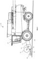
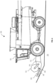
- FIG. 3 is a simplified side view of an agricultural harvester 300 that includes the header 200 ( FIG. 2 ) coupled to the combine harvester 100 ( FIG. 1 ).
- the header 200 may also include reel 302 configured to direct crop material toward the harvesting tool 204 ( FIG. 2 ) and a wheel 304 configured to lead the harvesting tool 204 when the header 200 is carried by the combine harvester 100 through an agricultural field.
- the wheel 304 may be connected to an arm 306 and operable to rotate along a soil surface ahead of the harvesting tool 204.
- the arm 306 may in turn be attached to the header 200 at a pivot point 308.
- the arm 306 is configured to rotate about the pivot point 308, so that the wheel 304 can remain in contact with the ground 310 ( i.e., the soil surface) even when the ground 310 is not flat.
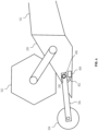
- FIG. 4 shows the header 200 in more detail.
- an angle sensor 402 may be coupled to the arm 306 and configured to detect an angular orientation of the arm 306.
- the angle sensor 402 may include a transmitter 404 configured to generate a signal correlated to the angular orientation of the arm 306 or the minimum distance from the ground 310 to the harvesting tool 204.
- the signal may be transmitted to a control system associated with the combine harvester 100 (e.g., a computer having a user interface in the operator cab 108).
- the arm 306 may be pushed downward against the ground 310 ( FIG. 3 ) by a biasing member 406, such as a spring.
- a biasing member 406 such as a spring.
- the biasing member 406 may be a torsion spring, a coil spring, an air spring, etc.
- the biasing member 406 may be omitted, and the weight of the wheel 304 and arm 306 may provide downward force to keep the wheel 304 in contact with the ground 310.
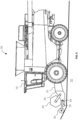
- FIG. 5 is a simplified side view illustrating the agricultural harvester 300 encountering a change in topography (depicted as a hill, a ridge, etc.).
- the wheel 304 reaches the hill ahead of the harvesting tool 204 ( FIG. 2 ).
- the arm 306 rotates upward, pushed by the wheel 304.
- the angle sensor 402 FIG. 4
- the control system may then adjust a height of the header 200 based on the detected topography that the harvesting tool 204 is about to encounter.
- the control system may cause the feederhouse 102 to raise the header 200 to match the contour of the ground 310, such that the harvesting tool 204 does not touch the ground 310.
- the wheel 304 may enable the operator to set the desired minimum distance from the harvesting tool 204 to the ground 310 lower than is desired for conventional harvesting headers because the wheel 304 (in combination with the control system) may protect the harvesting tool 204 from damage. That is, by moving the header 200 when a change in the elevation of the ground 310 is detected, the agricultural harvester 300 may avoid contacting the harvesting tool 204 with the ground 310.
- the operator may harvest an agricultural field faster and more safely than with conventional equipment, because adjustments may be made while the operator remains in the operator cab 108.
- FIG. 7 is a simplified side view showing a header 702 having a non-contact sensor 704.
- the non-contact sensor 704 may be, for example, a transducer configured to transmit and receive energy to and from the ground 310.
- the non-contact sensor 704 may transmit and receive ultrasonic waves, electromagnetic radiation ( e.g. , a laser), etc.
- the received energy may be reflected from the surface of the ground 310.
- the non-contact sensor 704 may generate a signal corresponding to a distance from the non-contact sensor 704 to the ground 310, and may send the signal to a control system associated with the combine harvester 100, as discussed above.
- Non-contact sensors are described in more detail in, for example, U.S.
- Patent 9,750,174 "Agricultural trench depth sensing systems, methods, and apparatus," issued September 5, 2017 ; U.S. Patent Application Publication 2019/0075710, “Seed Trench Depth Detection Systems,” published March 14, 2019 ; and U.S. Patent Application Publication 2019/0014714, “Agricultural Trench Depth Systems, Methods, and Apparatus,” published January 17, 2019 .
- FIG. 8 is a simplified flow chart illustrating a method 800 in which the header 200 or header 702 may be used for harvesting an agricultural field.
- the agricultural harvester is propelled through an agricultural field.
- a contour of a soil surface leading the at least one harvesting tool is sensed.
- the contour may be sensed by measuring an angle at which an arm leading the harvesting tool is oriented on a header frame.
- the contour may be sensed with a non-contact sensor by transmitting energy toward the soil surface and receiving energy reflected by the soil surface.
- a height of the harvesting header is adjusted based on the sensed contour.
- the height may be adjusted to avoid contacting the soil surface with the harvesting tool, or to maintain a selected height of the harvesting tool with respect to the soil surface.
- FIG. 9 An example computer-readable medium that may be devised is illustrated in FIG. 9 , wherein an implementation 900 includes a computer-readable storage medium 902 (e.g., a flash drive, CD-R, DVD-R, application-specific integrated circuit (ASIC), field-programmable gate array (FPGA), a platter of a hard disk drive, etc.), on which is computer-readable data 904.
- This computer-readable data 904 in turn includes a set of processor-executable instructions 906 configured to operate according to one or more of the principles set forth herein.
- the processor-executable instructions 906 may be configured to cause a computer associated with the combine harvester 100 ( FIG. 1 ) to perform operations 908 when executed via a processing unit, such as at least some of the example method 800 depicted in FIG. 8 .
- the processor-executable instructions 906 may be configured to implement a system, such as at least some of the example header 200 and combine harvester 100.
- Many such computer-readable media may be devised by those of ordinary skill in the art that are configured to operate in accordance with one or more of the techniques presented herein.
- the sensors disclosed herein may be used to direct a control system to move the harvesting header to prevent contact with the ground and to keep the harvesting header at a selected height for harvesting.
- a control system to move the harvesting header to prevent contact with the ground and to keep the harvesting header at a selected height for harvesting.
- the harvesting tool may be damaged.
- rocks and other debris can damage harvesting tools.
- the height of a conventional harvesting header may typically be set high enough to avoid ground contact and debris. However, this height may be greater than is ideal for certain crops.
- the sensors disclosed herein may enable the operator to set the height of the harvesting header lower than would be possible with conventional harvesting headers, yet the sensors may help avoid damage caused by terrain variations.
- multiple sensors may be placed on a single harvesting header.
- one sensor may be mounted to each divider 206 to provide contour information at two points.
- additional sensors may be located on appropriate mounts between the dividers 206.
Landscapes
- Life Sciences & Earth Sciences (AREA)
- Environmental Sciences (AREA)
- Combines (AREA)
- Harvester Elements (AREA)
Claims (8)
- Tête de moissonnage destinée à être utilisée avec une machine de moissonnage de culture, la tête de moissonnage comprenant :un bâti de tête (202) structuré de manière à être couplé à une partie avant de la machine de moissonnage ;au moins un outil de moissonnage (204) supporté par le bâti de tête et configuré de manière à couper le matériau à récolter ;un bras tournant (306) couplé au bâti de tête (202) au niveau d'un point de pivot (308) et s'étendant à l'avant du au moins un outil de moissonnage (204) lorsque la tête de moissonnage est utilisée afin de couper le matériau à récolter ;une roue (304) couplée au bras tournant (306) et configurée de manière rouler le long d'une surface du sol guidant le au moins un outil de moissonnage (204) lorsque la tête de moissonnage est utilisée afin de couper le matériau à récolter dans un champ agricole ; etun capteur (402) couplé au bâti de tête (202) au niveau du point de pivot (308), caractérisée en ce que le capteur (402) est configuré de manière à fournir un signal à la machine de moissonnage, le signal étant corrélé à l'angle du bras tournant (306) par rapport au bâti de tête (202).
- Moissonneuse agricole, comprenant :un châssis (104) ;un compartiment d'alimentation (102) supporté par le châssis (104) ;un dispositif de traitement (114) supporté par le châssis (104) et structuré de manière à recevoir le matériau à récolter à partir du compartiment d'alimentation (102) ;une trémie à grain (116) supportée par le châssis (104) et structurée de manière à recevoir le grain traité à partir du dispositif de traitement (114) ;une tête de moissonnage selon la revendication 1, couplée au compartiment d'alimentation (102) et configurée de manière à couper le grain ; etun dispositif de commande configuré de manière à ajuster une position de la tête de moissonnage par rapport à la moissonneuse agricole au moins en partie sur la base de l'angle mesuré du bras tournant.
- Moissonneuse agricole selon la revendication 2, dans laquelle le capteur (402) est configuré de manière transmettre un signal au dispositif de commande.
- Moissonneuse agricole selon la revendication 3, dans laquelle le signal est corrélé à une distance minimum à partir de la tête de moissonnage jusqu'à la surface du sol.
- Procédé de commande d'une moissonneuse agricole, le procédé comprenant :la propulsion de la moissonneuse agricole selon la revendication 2 à travers un champ agricole ;la détection d'un profil d'une surface du sol guidant le au moins un outil de moissonnage ; etle réglage d'une hauteur de la tête de moissonnage au moins en partie sur la base du profil détecté.
- Procédé selon la revendication 5, dans lequel le réglage de la hauteur de la tête de moissonnage comprend le soulèvement de la tête de moissonnage afin d'éviter l'entrée en contact de la surface du sol avec le au moins un outil de moissonnage.
- Procédé selon la revendication 5 ou 6, dans lequel le réglage de la hauteur de la tête de moissonnage comprend le maintien d'une hauteur sélectionnée du au moins un outil de moissonnage par rapport à la surface du sol.
- Procédé selon la revendication 5 ou 7, dans lequel la détection d'un profil d'une surface du sol guidant le au moins un outil de moissonnage comprend la mesure d'un angle d'un bras guidant le au moins un outil de moissonnage.
Applications Claiming Priority (2)
| Application Number | Priority Date | Filing Date | Title |
|---|---|---|---|
| GB201913215A GB201913215D0 (en) | 2019-09-13 | 2019-09-13 | Harvesting headers having leading sensors, agricultural machines carrying such headers, and related methods |
| PCT/EP2020/060767 WO2021047799A1 (fr) | 2019-09-13 | 2020-04-16 | Têtes de récolte ayant des capteurs avant, machines agricoles portant de telles têtes de récolte, et procédés associés |
Publications (2)
| Publication Number | Publication Date |
|---|---|
| EP4027770A1 EP4027770A1 (fr) | 2022-07-20 |
| EP4027770B1 true EP4027770B1 (fr) | 2024-09-25 |
Family
ID=68315347
Family Applications (1)
| Application Number | Title | Priority Date | Filing Date |
|---|---|---|---|
| EP20719638.7A Active EP4027770B1 (fr) | 2019-09-13 | 2020-04-16 | Têtes de récolte ayant des capteurs de hauteur, machines agricoles portant de telles têtes et procédés associés |
Country Status (6)
| Country | Link |
|---|---|
| US (1) | US20220338416A1 (fr) |
| EP (1) | EP4027770B1 (fr) |
| CA (1) | CA3152937A1 (fr) |
| GB (1) | GB201913215D0 (fr) |
| HU (1) | HUE069336T2 (fr) |
| WO (1) | WO2021047799A1 (fr) |
Families Citing this family (11)
| Publication number | Priority date | Publication date | Assignee | Title |
|---|---|---|---|---|
| US12364181B2 (en) | 2020-11-02 | 2025-07-22 | Deere & Company | Agricultural characteristic confidence and control |
| US12022772B2 (en) | 2021-01-22 | 2024-07-02 | Deere & Company | Agricultural header control |
| US12396387B2 (en) | 2021-07-20 | 2025-08-26 | Deere & Company | Automated lockout system for header |
| US12396393B2 (en) | 2021-07-20 | 2025-08-26 | Deer & Company | Automated lockout system for header |
| US12402561B2 (en) | 2021-07-20 | 2025-09-02 | Deere & Company | Automated lockout system for header |
| US12575497B2 (en) | 2021-09-08 | 2026-03-17 | Deere & Company | Automated lockout system for header |
| WO2023081430A1 (fr) * | 2021-11-05 | 2023-05-11 | Cnh Industrial America Llc | Capteurs sans contact dans une rampe de récolte d'un collecteur agricole |
| US12550821B2 (en) | 2022-03-15 | 2026-02-17 | Deere & Company | Systems and methods for predictive reel control |
| US12302788B2 (en) | 2022-04-08 | 2025-05-20 | Deere &Company | Residue characteristic confidence and control |
| US12507628B2 (en) | 2022-10-13 | 2025-12-30 | Deere & Company | Agricultural system with deck plate positioning control |
| US12582038B2 (en) * | 2024-02-27 | 2026-03-24 | Cnh Industrial America Llc | System and method for controlling the operation of an agricultural harvester |
Citations (1)
| Publication number | Priority date | Publication date | Assignee | Title |
|---|---|---|---|---|
| US5794421A (en) * | 1994-03-03 | 1998-08-18 | Robert Bosch Gmbh | Device for regulating the distance from the ground of a working unit of an agricultural machine |
Family Cites Families (17)
| Publication number | Priority date | Publication date | Assignee | Title |
|---|---|---|---|---|
| DE2261558C3 (de) * | 1972-12-15 | 1982-07-08 | Maschinenfabrik Fahr Ag Gottmadingen, 7702 Gottmadingen | Elektrohydraulische Steuerung für die Höhenverstellung des Mähtisches eines Mähdreschers oder einer vergleichbaren Erntemaschine |
| US4141200A (en) * | 1976-10-27 | 1979-02-27 | Johnson Farm Machinery Co., Inc. | Automatic header adjustment for harvesters |
| US4171606A (en) * | 1978-06-30 | 1979-10-23 | Deere & Company | Attitude control for a harvester pickup |
| US4414792A (en) * | 1982-03-30 | 1983-11-15 | Blackwelders | Height control for agricultural machine |
| US7886511B2 (en) | 2008-05-09 | 2011-02-15 | Agco Corporation | Draper head with flexible cutterbar having rigid center section |
| US8146335B2 (en) * | 2010-05-07 | 2012-04-03 | Deere & Company | Sensor for a header height control system |
| US8857143B2 (en) | 2011-12-28 | 2014-10-14 | Agco Corporation | Frame for harvesting header with continuous section |
| US9148998B2 (en) * | 2012-08-11 | 2015-10-06 | Deere & Company | Header height control system |
| EP3656196B1 (fr) | 2012-10-24 | 2022-08-03 | Precision Planting LLC | Appareil de détection de profondeur de tranchées agricoles |
| GB201223544D0 (en) | 2012-12-21 | 2013-02-13 | Agco Int Gmbh | Power take off drive system for a vehicle |
| US20150101300A1 (en) * | 2013-10-15 | 2015-04-16 | Deere & Company | Header Height Sensor |
| US10194588B2 (en) | 2014-12-30 | 2019-02-05 | Agco Corporation | Corn header configured to reduce kernel losses |
| CN109068574B (zh) | 2016-02-19 | 2022-06-10 | 精密种植有限责任公司 | 农用地沟深度系统、方法和设备 |
| BR112018073234B1 (pt) | 2016-05-13 | 2023-03-07 | Precision Planting Llc | Implemento agrícola, sensor adaptado para ser montado a um implemento agrícola e método para ajustar o conjunto de fechamento de sulco do implemento agrícola |
| US9980431B2 (en) * | 2016-09-12 | 2018-05-29 | Cnh Industrial America Llc | Header height control system with multiple height sensors |
| US10687466B2 (en) * | 2018-01-29 | 2020-06-23 | Cnh Industrial America Llc | Predictive header height control system |
| US11375663B2 (en) * | 2019-02-15 | 2022-07-05 | Deere & Company | Ground contour sensing system for crop mowing head |
-
2019
- 2019-09-13 GB GB201913215A patent/GB201913215D0/en not_active Ceased
-
2020
- 2020-04-16 WO PCT/EP2020/060767 patent/WO2021047799A1/fr not_active Ceased
- 2020-04-16 EP EP20719638.7A patent/EP4027770B1/fr active Active
- 2020-04-16 US US17/753,733 patent/US20220338416A1/en not_active Abandoned
- 2020-04-16 HU HUE20719638A patent/HUE069336T2/hu unknown
- 2020-04-16 CA CA3152937A patent/CA3152937A1/fr active Pending
Patent Citations (1)
| Publication number | Priority date | Publication date | Assignee | Title |
|---|---|---|---|---|
| US5794421A (en) * | 1994-03-03 | 1998-08-18 | Robert Bosch Gmbh | Device for regulating the distance from the ground of a working unit of an agricultural machine |
Also Published As
| Publication number | Publication date |
|---|---|
| HUE069336T2 (hu) | 2025-02-28 |
| WO2021047799A1 (fr) | 2021-03-18 |
| US20220338416A1 (en) | 2022-10-27 |
| GB201913215D0 (en) | 2019-10-30 |
| EP4027770A1 (fr) | 2022-07-20 |
| CA3152937A1 (fr) | 2021-03-18 |
Similar Documents
| Publication | Publication Date | Title |
|---|---|---|
| EP4027770B1 (fr) | Têtes de récolte ayant des capteurs de hauteur, machines agricoles portant de telles têtes et procédés associés | |
| US20230172106A1 (en) | Harvesters, harvesting headers, and methods of operating agricultural machines using crop lifters | |
| EP3469878B1 (fr) | Centre de roulis pour bras de commande de structure de fixation de moissonneuse | |
| EP4081019B1 (fr) | Commande d'un collecteur de moissonneuse-batteuse durant un mode hors récolte | |
| US10182525B2 (en) | Feeder and header positioning method | |
| EP3879961B1 (fr) | Système et procédé de réglage de paramètres pour tête agricole d'abattage à segments multiples | |
| US20240357968A1 (en) | Sensor support system for a harvesting implement of an agricultural harvester | |
| EP4009766B1 (fr) | Chamre d'alimentation, machine agricole de récolte, et méthode pour connecter une tête de récolte à une maschine agricole de récolte | |
| EP3998845B1 (fr) | Ensembles chambre d'alimentation, moissonneuses agricoles, et procédés de raccordement de becs cueilleurs de récolte à des moissonneuses agricoles | |
| EP4002987B1 (fr) | Points diviseurs, becs cueilleurs de récolte conçus pour recevoir des points diviseurs amovibles, et procédés associés | |
| US20240099191A1 (en) | Header mounted radar for ground detection and active header control | |
| US12356891B2 (en) | Rotatable wing dividers, harvesting headers, and agricultural machines having rotatable wing dividers | |
| US12364196B2 (en) | Feederhouse tilt frame for an agricultural harvester | |
| EP3646700B1 (fr) | Système d'estimation de biomasse de moissonneuse agricole | |
| WO2023081430A1 (fr) | Capteurs sans contact dans une rampe de récolte d'un collecteur agricole | |
| JP2000209903A (ja) | コンバイン用自動方向制御のセンサ装置 |
Legal Events
| Date | Code | Title | Description |
|---|---|---|---|
| STAA | Information on the status of an ep patent application or granted ep patent |
Free format text: STATUS: UNKNOWN |
|
| STAA | Information on the status of an ep patent application or granted ep patent |
Free format text: STATUS: THE INTERNATIONAL PUBLICATION HAS BEEN MADE |
|
| PUAI | Public reference made under article 153(3) epc to a published international application that has entered the european phase |
Free format text: ORIGINAL CODE: 0009012 |
|
| STAA | Information on the status of an ep patent application or granted ep patent |
Free format text: STATUS: REQUEST FOR EXAMINATION WAS MADE |
|
| 17P | Request for examination filed |
Effective date: 20220413 |
|
| AK | Designated contracting states |
Kind code of ref document: A1 Designated state(s): AL AT BE BG CH CY CZ DE DK EE ES FI FR GB GR HR HU IE IS IT LI LT LU LV MC MK MT NL NO PL PT RO RS SE SI SK SM TR |
|
| DAV | Request for validation of the european patent (deleted) | ||
| DAX | Request for extension of the european patent (deleted) | ||
| P01 | Opt-out of the competence of the unified patent court (upc) registered |
Effective date: 20230518 |
|
| STAA | Information on the status of an ep patent application or granted ep patent |
Free format text: STATUS: EXAMINATION IS IN PROGRESS |
|
| 17Q | First examination report despatched |
Effective date: 20240408 |
|
| GRAP | Despatch of communication of intention to grant a patent |
Free format text: ORIGINAL CODE: EPIDOSNIGR1 |
|
| STAA | Information on the status of an ep patent application or granted ep patent |
Free format text: STATUS: GRANT OF PATENT IS INTENDED |
|
| GRAS | Grant fee paid |
Free format text: ORIGINAL CODE: EPIDOSNIGR3 |
|
| GRAA | (expected) grant |
Free format text: ORIGINAL CODE: 0009210 |
|
| STAA | Information on the status of an ep patent application or granted ep patent |
Free format text: STATUS: THE PATENT HAS BEEN GRANTED |
|
| INTG | Intention to grant announced |
Effective date: 20240726 |
|
| AK | Designated contracting states |
Kind code of ref document: B1 Designated state(s): AL AT BE BG CH CY CZ DE DK EE ES FI FR GB GR HR HU IE IS IT LI LT LU LV MC MK MT NL NO PL PT RO RS SE SI SK SM TR |
|
| REG | Reference to a national code |
Ref country code: GB Ref legal event code: FG4D |
|
| REG | Reference to a national code |
Ref country code: CH Ref legal event code: EP |
|
| REG | Reference to a national code |
Ref country code: DE Ref legal event code: R096 Ref document number: 602020038283 Country of ref document: DE |
|
| REG | Reference to a national code |
Ref country code: IE Ref legal event code: FG4D |
|
| REG | Reference to a national code |
Ref country code: LT Ref legal event code: MG9D |
|
| PG25 | Lapsed in a contracting state [announced via postgrant information from national office to epo] |
Ref country code: NO Free format text: LAPSE BECAUSE OF FAILURE TO SUBMIT A TRANSLATION OF THE DESCRIPTION OR TO PAY THE FEE WITHIN THE PRESCRIBED TIME-LIMIT Effective date: 20241225 |
|
| PG25 | Lapsed in a contracting state [announced via postgrant information from national office to epo] |
Ref country code: GR Free format text: LAPSE BECAUSE OF FAILURE TO SUBMIT A TRANSLATION OF THE DESCRIPTION OR TO PAY THE FEE WITHIN THE PRESCRIBED TIME-LIMIT Effective date: 20241226 Ref country code: FI Free format text: LAPSE BECAUSE OF FAILURE TO SUBMIT A TRANSLATION OF THE DESCRIPTION OR TO PAY THE FEE WITHIN THE PRESCRIBED TIME-LIMIT Effective date: 20240925 |
|
| PG25 | Lapsed in a contracting state [announced via postgrant information from national office to epo] |
Ref country code: BG Free format text: LAPSE BECAUSE OF FAILURE TO SUBMIT A TRANSLATION OF THE DESCRIPTION OR TO PAY THE FEE WITHIN THE PRESCRIBED TIME-LIMIT Effective date: 20240925 |
|
| PG25 | Lapsed in a contracting state [announced via postgrant information from national office to epo] |
Ref country code: LV Free format text: LAPSE BECAUSE OF FAILURE TO SUBMIT A TRANSLATION OF THE DESCRIPTION OR TO PAY THE FEE WITHIN THE PRESCRIBED TIME-LIMIT Effective date: 20240925 |
|
| PG25 | Lapsed in a contracting state [announced via postgrant information from national office to epo] |
Ref country code: RS Free format text: LAPSE BECAUSE OF FAILURE TO SUBMIT A TRANSLATION OF THE DESCRIPTION OR TO PAY THE FEE WITHIN THE PRESCRIBED TIME-LIMIT Effective date: 20241225 |
|
| REG | Reference to a national code |
Ref country code: NL Ref legal event code: MP Effective date: 20240925 |
|
| PG25 | Lapsed in a contracting state [announced via postgrant information from national office to epo] |
Ref country code: RS Free format text: LAPSE BECAUSE OF FAILURE TO SUBMIT A TRANSLATION OF THE DESCRIPTION OR TO PAY THE FEE WITHIN THE PRESCRIBED TIME-LIMIT Effective date: 20241225 Ref country code: NO Free format text: LAPSE BECAUSE OF FAILURE TO SUBMIT A TRANSLATION OF THE DESCRIPTION OR TO PAY THE FEE WITHIN THE PRESCRIBED TIME-LIMIT Effective date: 20241225 Ref country code: LV Free format text: LAPSE BECAUSE OF FAILURE TO SUBMIT A TRANSLATION OF THE DESCRIPTION OR TO PAY THE FEE WITHIN THE PRESCRIBED TIME-LIMIT Effective date: 20240925 Ref country code: GR Free format text: LAPSE BECAUSE OF FAILURE TO SUBMIT A TRANSLATION OF THE DESCRIPTION OR TO PAY THE FEE WITHIN THE PRESCRIBED TIME-LIMIT Effective date: 20241226 Ref country code: FI Free format text: LAPSE BECAUSE OF FAILURE TO SUBMIT A TRANSLATION OF THE DESCRIPTION OR TO PAY THE FEE WITHIN THE PRESCRIBED TIME-LIMIT Effective date: 20240925 Ref country code: BG Free format text: LAPSE BECAUSE OF FAILURE TO SUBMIT A TRANSLATION OF THE DESCRIPTION OR TO PAY THE FEE WITHIN THE PRESCRIBED TIME-LIMIT Effective date: 20240925 |
|
| REG | Reference to a national code |
Ref country code: AT Ref legal event code: MK05 Ref document number: 1725828 Country of ref document: AT Kind code of ref document: T Effective date: 20240925 |
|
| PG25 | Lapsed in a contracting state [announced via postgrant information from national office to epo] |
Ref country code: NL Free format text: LAPSE BECAUSE OF FAILURE TO SUBMIT A TRANSLATION OF THE DESCRIPTION OR TO PAY THE FEE WITHIN THE PRESCRIBED TIME-LIMIT Effective date: 20240925 |
|
| REG | Reference to a national code |
Ref country code: HU Ref legal event code: AG4A Ref document number: E069336 Country of ref document: HU |
|
| PG25 | Lapsed in a contracting state [announced via postgrant information from national office to epo] |
Ref country code: IS Free format text: LAPSE BECAUSE OF FAILURE TO SUBMIT A TRANSLATION OF THE DESCRIPTION OR TO PAY THE FEE WITHIN THE PRESCRIBED TIME-LIMIT Effective date: 20250125 Ref country code: PT Free format text: LAPSE BECAUSE OF FAILURE TO SUBMIT A TRANSLATION OF THE DESCRIPTION OR TO PAY THE FEE WITHIN THE PRESCRIBED TIME-LIMIT Effective date: 20250127 |
|
| PG25 | Lapsed in a contracting state [announced via postgrant information from national office to epo] |
Ref country code: RO Free format text: LAPSE BECAUSE OF FAILURE TO SUBMIT A TRANSLATION OF THE DESCRIPTION OR TO PAY THE FEE WITHIN THE PRESCRIBED TIME-LIMIT Effective date: 20240925 Ref country code: SM Free format text: LAPSE BECAUSE OF FAILURE TO SUBMIT A TRANSLATION OF THE DESCRIPTION OR TO PAY THE FEE WITHIN THE PRESCRIBED TIME-LIMIT Effective date: 20240925 |
|
| PG25 | Lapsed in a contracting state [announced via postgrant information from national office to epo] |
Ref country code: ES Free format text: LAPSE BECAUSE OF FAILURE TO SUBMIT A TRANSLATION OF THE DESCRIPTION OR TO PAY THE FEE WITHIN THE PRESCRIBED TIME-LIMIT Effective date: 20240925 |
|
| PG25 | Lapsed in a contracting state [announced via postgrant information from national office to epo] |
Ref country code: EE Free format text: LAPSE BECAUSE OF FAILURE TO SUBMIT A TRANSLATION OF THE DESCRIPTION OR TO PAY THE FEE WITHIN THE PRESCRIBED TIME-LIMIT Effective date: 20240925 Ref country code: AT Free format text: LAPSE BECAUSE OF FAILURE TO SUBMIT A TRANSLATION OF THE DESCRIPTION OR TO PAY THE FEE WITHIN THE PRESCRIBED TIME-LIMIT Effective date: 20240925 |
|
| PG25 | Lapsed in a contracting state [announced via postgrant information from national office to epo] |
Ref country code: CZ Free format text: LAPSE BECAUSE OF FAILURE TO SUBMIT A TRANSLATION OF THE DESCRIPTION OR TO PAY THE FEE WITHIN THE PRESCRIBED TIME-LIMIT Effective date: 20240925 Ref country code: PL Free format text: LAPSE BECAUSE OF FAILURE TO SUBMIT A TRANSLATION OF THE DESCRIPTION OR TO PAY THE FEE WITHIN THE PRESCRIBED TIME-LIMIT Effective date: 20240925 |
|
| PG25 | Lapsed in a contracting state [announced via postgrant information from national office to epo] |
Ref country code: SK Free format text: LAPSE BECAUSE OF FAILURE TO SUBMIT A TRANSLATION OF THE DESCRIPTION OR TO PAY THE FEE WITHIN THE PRESCRIBED TIME-LIMIT Effective date: 20240925 Ref country code: IT Free format text: LAPSE BECAUSE OF FAILURE TO SUBMIT A TRANSLATION OF THE DESCRIPTION OR TO PAY THE FEE WITHIN THE PRESCRIBED TIME-LIMIT Effective date: 20240925 |
|
| REG | Reference to a national code |
Ref country code: DE Ref legal event code: R097 Ref document number: 602020038283 Country of ref document: DE |
|
| PG25 | Lapsed in a contracting state [announced via postgrant information from national office to epo] |
Ref country code: DK Free format text: LAPSE BECAUSE OF FAILURE TO SUBMIT A TRANSLATION OF THE DESCRIPTION OR TO PAY THE FEE WITHIN THE PRESCRIBED TIME-LIMIT Effective date: 20240925 |
|
| PGFP | Annual fee paid to national office [announced via postgrant information from national office to epo] |
Ref country code: HU Payment date: 20250424 Year of fee payment: 6 |
|
| PGFP | Annual fee paid to national office [announced via postgrant information from national office to epo] |
Ref country code: FR Payment date: 20250425 Year of fee payment: 6 |
|
| PLBE | No opposition filed within time limit |
Free format text: ORIGINAL CODE: 0009261 |
|
| STAA | Information on the status of an ep patent application or granted ep patent |
Free format text: STATUS: NO OPPOSITION FILED WITHIN TIME LIMIT |
|
| 26N | No opposition filed |
Effective date: 20250626 |
|
| PG25 | Lapsed in a contracting state [announced via postgrant information from national office to epo] |
Ref country code: SE Free format text: LAPSE BECAUSE OF FAILURE TO SUBMIT A TRANSLATION OF THE DESCRIPTION OR TO PAY THE FEE WITHIN THE PRESCRIBED TIME-LIMIT Effective date: 20240925 |
|
| REG | Reference to a national code |
Ref country code: DE Ref legal event code: R119 Ref document number: 602020038283 Country of ref document: DE |
|
| REG | Reference to a national code |
Ref country code: CH Ref legal event code: H13 Free format text: ST27 STATUS EVENT CODE: U-0-0-H10-H13 (AS PROVIDED BY THE NATIONAL OFFICE) Effective date: 20251125 |
|
| PG25 | Lapsed in a contracting state [announced via postgrant information from national office to epo] |
Ref country code: LU Free format text: LAPSE BECAUSE OF NON-PAYMENT OF DUE FEES Effective date: 20250416 |
|
| PG25 | Lapsed in a contracting state [announced via postgrant information from national office to epo] |
Ref country code: MC Free format text: LAPSE BECAUSE OF FAILURE TO SUBMIT A TRANSLATION OF THE DESCRIPTION OR TO PAY THE FEE WITHIN THE PRESCRIBED TIME-LIMIT Effective date: 20240925 |
|
| GBPC | Gb: european patent ceased through non-payment of renewal fee |
Effective date: 20250416 |
|
| REG | Reference to a national code |
Ref country code: BE Ref legal event code: MM Effective date: 20250430 |
|
| PG25 | Lapsed in a contracting state [announced via postgrant information from national office to epo] |
Ref country code: DE Free format text: LAPSE BECAUSE OF NON-PAYMENT OF DUE FEES Effective date: 20251104 |
|
| PG25 | Lapsed in a contracting state [announced via postgrant information from national office to epo] |
Ref country code: GB Free format text: LAPSE BECAUSE OF NON-PAYMENT OF DUE FEES Effective date: 20250416 |
|
| PG25 | Lapsed in a contracting state [announced via postgrant information from national office to epo] |
Ref country code: HR Free format text: LAPSE BECAUSE OF FAILURE TO SUBMIT A TRANSLATION OF THE DESCRIPTION OR TO PAY THE FEE WITHIN THE PRESCRIBED TIME-LIMIT Effective date: 20240925 |
|
| PG25 | Lapsed in a contracting state [announced via postgrant information from national office to epo] |
Ref country code: BE Free format text: LAPSE BECAUSE OF NON-PAYMENT OF DUE FEES Effective date: 20250430 |
|
| PG25 | Lapsed in a contracting state [announced via postgrant information from national office to epo] |
Ref country code: CH Free format text: LAPSE BECAUSE OF NON-PAYMENT OF DUE FEES Effective date: 20250430 |
|
| PG25 | Lapsed in a contracting state [announced via postgrant information from national office to epo] |
Ref country code: IE Free format text: LAPSE BECAUSE OF NON-PAYMENT OF DUE FEES Effective date: 20250416 |