EP4027711A1 - Uplink control and data transmission in multiflow-enabled networks - Google Patents
Uplink control and data transmission in multiflow-enabled networks Download PDFInfo
- Publication number
- EP4027711A1 EP4027711A1 EP22159119.1A EP22159119A EP4027711A1 EP 4027711 A1 EP4027711 A1 EP 4027711A1 EP 22159119 A EP22159119 A EP 22159119A EP 4027711 A1 EP4027711 A1 EP 4027711A1
- Authority
- EP
- European Patent Office
- Prior art keywords
- uplink
- nodes
- multiflow
- transmissions
- cell
- Prior art date
- Legal status (The legal status is an assumption and is not a legal conclusion. Google has not performed a legal analysis and makes no representation as to the accuracy of the status listed.)
- Pending
Links
- 230000005540 biological transmission Effects 0.000 title claims abstract description 279
- 238000000034 method Methods 0.000 claims abstract description 59
- 238000004891 communication Methods 0.000 claims description 103
- 238000004590 computer program Methods 0.000 claims description 34
- 238000009482 thermal adhesion granulation Methods 0.000 claims 4
- 230000002776 aggregation Effects 0.000 abstract description 6
- 238000004220 aggregation Methods 0.000 abstract description 6
- 230000011664 signaling Effects 0.000 abstract description 6
- 230000008901 benefit Effects 0.000 abstract description 5
- 230000008054 signal transmission Effects 0.000 description 44
- 230000015654 memory Effects 0.000 description 36
- 238000010586 diagram Methods 0.000 description 28
- 238000012913 prioritisation Methods 0.000 description 19
- 239000000969 carrier Substances 0.000 description 14
- 238000005516 engineering process Methods 0.000 description 12
- 230000008569 process Effects 0.000 description 9
- 238000013461 design Methods 0.000 description 5
- 230000001360 synchronised effect Effects 0.000 description 5
- 239000000835 fiber Substances 0.000 description 4
- 230000002452 interceptive effect Effects 0.000 description 4
- 238000000638 solvent extraction Methods 0.000 description 4
- 230000003044 adaptive effect Effects 0.000 description 3
- 230000006870 function Effects 0.000 description 3
- 238000007726 management method Methods 0.000 description 3
- 238000005259 measurement Methods 0.000 description 3
- 230000007246 mechanism Effects 0.000 description 3
- 238000010295 mobile communication Methods 0.000 description 3
- 230000003287 optical effect Effects 0.000 description 3
- 230000003595 spectral effect Effects 0.000 description 3
- 238000001228 spectrum Methods 0.000 description 3
- 230000009471 action Effects 0.000 description 2
- 238000013459 approach Methods 0.000 description 2
- 230000008520 organization Effects 0.000 description 2
- 239000002245 particle Substances 0.000 description 2
- 230000002829 reductive effect Effects 0.000 description 2
- 230000004308 accommodation Effects 0.000 description 1
- 230000006399 behavior Effects 0.000 description 1
- 230000001413 cellular effect Effects 0.000 description 1
- 230000008859 change Effects 0.000 description 1
- 230000003247 decreasing effect Effects 0.000 description 1
- 230000001934 delay Effects 0.000 description 1
- 230000003111 delayed effect Effects 0.000 description 1
- 230000001419 dependent effect Effects 0.000 description 1
- 238000001514 detection method Methods 0.000 description 1
- 230000003292 diminished effect Effects 0.000 description 1
- 230000000670 limiting effect Effects 0.000 description 1
- 230000007774 longterm Effects 0.000 description 1
- 238000012986 modification Methods 0.000 description 1
- 230000004048 modification Effects 0.000 description 1
- 238000012544 monitoring process Methods 0.000 description 1
- 238000005192 partition Methods 0.000 description 1
- 230000000737 periodic effect Effects 0.000 description 1
- 238000012545 processing Methods 0.000 description 1
- 238000012827 research and development Methods 0.000 description 1
- 238000013468 resource allocation Methods 0.000 description 1
- 230000004044 response Effects 0.000 description 1
- 230000002441 reversible effect Effects 0.000 description 1
- 238000012546 transfer Methods 0.000 description 1
- 238000011144 upstream manufacturing Methods 0.000 description 1
Images

Classifications
-
- H—ELECTRICITY
- H04—ELECTRIC COMMUNICATION TECHNIQUE
- H04L—TRANSMISSION OF DIGITAL INFORMATION, e.g. TELEGRAPHIC COMMUNICATION
- H04L5/00—Arrangements affording multiple use of the transmission path
- H04L5/003—Arrangements for allocating sub-channels of the transmission path
- H04L5/0078—Timing of allocation
-
- H—ELECTRICITY
- H04—ELECTRIC COMMUNICATION TECHNIQUE
- H04L—TRANSMISSION OF DIGITAL INFORMATION, e.g. TELEGRAPHIC COMMUNICATION
- H04L5/00—Arrangements affording multiple use of the transmission path
- H04L5/003—Arrangements for allocating sub-channels of the transmission path
- H04L5/0053—Allocation of signalling, i.e. of overhead other than pilot signals
-
- H—ELECTRICITY
- H04—ELECTRIC COMMUNICATION TECHNIQUE
- H04L—TRANSMISSION OF DIGITAL INFORMATION, e.g. TELEGRAPHIC COMMUNICATION
- H04L5/00—Arrangements affording multiple use of the transmission path
- H04L5/003—Arrangements for allocating sub-channels of the transmission path
- H04L5/0032—Distributed allocation, i.e. involving a plurality of allocating devices, each making partial allocation
- H04L5/0035—Resource allocation in a cooperative multipoint environment
-
- H—ELECTRICITY
- H04—ELECTRIC COMMUNICATION TECHNIQUE
- H04W—WIRELESS COMMUNICATION NETWORKS
- H04W52/00—Power management, e.g. Transmission Power Control [TPC] or power classes
- H04W52/02—Power saving arrangements
- H04W52/0209—Power saving arrangements in terminal devices
- H04W52/0212—Power saving arrangements in terminal devices managed by the network, e.g. network or access point is leader and terminal is follower
- H04W52/0216—Power saving arrangements in terminal devices managed by the network, e.g. network or access point is leader and terminal is follower using a pre-established activity schedule, e.g. traffic indication frame
-
- H—ELECTRICITY
- H04—ELECTRIC COMMUNICATION TECHNIQUE
- H04W—WIRELESS COMMUNICATION NETWORKS
- H04W52/00—Power management, e.g. Transmission Power Control [TPC] or power classes
- H04W52/04—Transmission power control [TPC]
- H04W52/06—TPC algorithms
- H04W52/14—Separate analysis of uplink or downlink
- H04W52/146—Uplink power control
-
- H—ELECTRICITY
- H04—ELECTRIC COMMUNICATION TECHNIQUE
- H04W—WIRELESS COMMUNICATION NETWORKS
- H04W52/00—Power management, e.g. Transmission Power Control [TPC] or power classes
- H04W52/04—Transmission power control [TPC]
- H04W52/30—Transmission power control [TPC] using constraints in the total amount of available transmission power
- H04W52/32—TPC of broadcast or control channels
- H04W52/325—Power control of control or pilot channels
-
- H—ELECTRICITY
- H04—ELECTRIC COMMUNICATION TECHNIQUE
- H04W—WIRELESS COMMUNICATION NETWORKS
- H04W52/00—Power management, e.g. Transmission Power Control [TPC] or power classes
- H04W52/04—Transmission power control [TPC]
- H04W52/30—Transmission power control [TPC] using constraints in the total amount of available transmission power
- H04W52/34—TPC management, i.e. sharing limited amount of power among users or channels or data types, e.g. cell loading
- H04W52/346—TPC management, i.e. sharing limited amount of power among users or channels or data types, e.g. cell loading distributing total power among users or channels
-
- H—ELECTRICITY
- H04—ELECTRIC COMMUNICATION TECHNIQUE
- H04W—WIRELESS COMMUNICATION NETWORKS
- H04W52/00—Power management, e.g. Transmission Power Control [TPC] or power classes
- H04W52/04—Transmission power control [TPC]
- H04W52/30—Transmission power control [TPC] using constraints in the total amount of available transmission power
- H04W52/36—Transmission power control [TPC] using constraints in the total amount of available transmission power with a discrete range or set of values, e.g. step size, ramping or offsets
- H04W52/365—Power headroom reporting
-
- H—ELECTRICITY
- H04—ELECTRIC COMMUNICATION TECHNIQUE
- H04W—WIRELESS COMMUNICATION NETWORKS
- H04W72/00—Local resource management
- H04W72/20—Control channels or signalling for resource management
- H04W72/21—Control channels or signalling for resource management in the uplink direction of a wireless link, i.e. towards the network
-
- H—ELECTRICITY
- H04—ELECTRIC COMMUNICATION TECHNIQUE
- H04L—TRANSMISSION OF DIGITAL INFORMATION, e.g. TELEGRAPHIC COMMUNICATION
- H04L25/00—Baseband systems
- H04L25/02—Details ; arrangements for supplying electrical power along data transmission lines
- H04L25/0202—Channel estimation
- H04L25/0224—Channel estimation using sounding signals
-
- H—ELECTRICITY
- H04—ELECTRIC COMMUNICATION TECHNIQUE
- H04L—TRANSMISSION OF DIGITAL INFORMATION, e.g. TELEGRAPHIC COMMUNICATION
- H04L5/00—Arrangements affording multiple use of the transmission path
- H04L5/0001—Arrangements for dividing the transmission path
- H04L5/0003—Two-dimensional division
- H04L5/0005—Time-frequency
- H04L5/0007—Time-frequency the frequencies being orthogonal, e.g. OFDM(A) or DMT
- H04L5/001—Time-frequency the frequencies being orthogonal, e.g. OFDM(A) or DMT the frequencies being arranged in component carriers
-
- H—ELECTRICITY
- H04—ELECTRIC COMMUNICATION TECHNIQUE
- H04L—TRANSMISSION OF DIGITAL INFORMATION, e.g. TELEGRAPHIC COMMUNICATION
- H04L5/00—Arrangements affording multiple use of the transmission path
- H04L5/003—Arrangements for allocating sub-channels of the transmission path
- H04L5/0042—Intra-user or intra-terminal allocation
-
- H—ELECTRICITY
- H04—ELECTRIC COMMUNICATION TECHNIQUE
- H04L—TRANSMISSION OF DIGITAL INFORMATION, e.g. TELEGRAPHIC COMMUNICATION
- H04L5/00—Arrangements affording multiple use of the transmission path
- H04L5/003—Arrangements for allocating sub-channels of the transmission path
- H04L5/0048—Allocation of pilot signals, i.e. of signals known to the receiver
-
- H—ELECTRICITY
- H04—ELECTRIC COMMUNICATION TECHNIQUE
- H04W—WIRELESS COMMUNICATION NETWORKS
- H04W56/00—Synchronisation arrangements
- H04W56/0005—Synchronisation arrangements synchronizing of arrival of multiple uplinks
-
- H—ELECTRICITY
- H04—ELECTRIC COMMUNICATION TECHNIQUE
- H04W—WIRELESS COMMUNICATION NETWORKS
- H04W56/00—Synchronisation arrangements
- H04W56/004—Synchronisation arrangements compensating for timing error of reception due to propagation delay
- H04W56/0045—Synchronisation arrangements compensating for timing error of reception due to propagation delay compensating for timing error by altering transmission time
-
- Y—GENERAL TAGGING OF NEW TECHNOLOGICAL DEVELOPMENTS; GENERAL TAGGING OF CROSS-SECTIONAL TECHNOLOGIES SPANNING OVER SEVERAL SECTIONS OF THE IPC; TECHNICAL SUBJECTS COVERED BY FORMER USPC CROSS-REFERENCE ART COLLECTIONS [XRACs] AND DIGESTS
- Y02—TECHNOLOGIES OR APPLICATIONS FOR MITIGATION OR ADAPTATION AGAINST CLIMATE CHANGE
- Y02D—CLIMATE CHANGE MITIGATION TECHNOLOGIES IN INFORMATION AND COMMUNICATION TECHNOLOGIES [ICT], I.E. INFORMATION AND COMMUNICATION TECHNOLOGIES AIMING AT THE REDUCTION OF THEIR OWN ENERGY USE
- Y02D30/00—Reducing energy consumption in communication networks
- Y02D30/70—Reducing energy consumption in communication networks in wireless communication networks
Definitions
- aspects of the present disclosure relate generally to wireless communication systems, and more particularly, to uplink control and data transmission in multiflow-enabled networks.
- Wireless communication networks are widely deployed to provide various communication services such as voice, video, packet data, messaging, broadcast, and the like. These wireless networks may be multiple-access networks capable of supporting multiple users by sharing the available network resources. Such networks, which are usually multiple access networks, support communications for multiple users by sharing the available network resources.
- UTRAN Universal Terrestrial Radio Access Network
- the UTRAN is the radio access network (RAN) defined as a part of the Universal Mobile Telecommunications System (UMTS), a third generation (3G) mobile phone technology supported by the 3rd Generation Partnership Project (3GPP).
- UMTS Universal Mobile Telecommunications System
- 3GPP 3rd Generation Partnership Project
- multiple-access network formats include Code Division Multiple Access (CDMA) networks, Time Division Multiple Access (TDMA) networks, Frequency Division Multiple Access (FDMA) networks, Orthogonal FDMA (OFDMA) networks, and Single-Carrier FDMA (SC-FDMA) networks.
- CDMA Code Division Multiple Access
- TDMA Time Division Multiple Access
- FDMA Frequency Division Multiple Access
- OFDMA Orthogonal FDMA
- SC-FDMA Single-Carrier FDMA
- a wireless communication network may include a number of base stations or node Bs that can support communication for a number of user equipments (UEs).
- a UE may communicate with a base station via downlink and uplink.
- the downlink (or forward link) refers to the communication link from the base station to the UE
- the uplink (or reverse link) refers to the communication link from the UE to the base station.
- a base station may transmit data and control information on the downlink to a UE and/or may receive data and control information on the uplink from the UE.
- a transmission from the base station may encounter interference due to transmissions from neighbor base stations or from other wireless radio frequency (RF) transmitters.
- RF radio frequency
- a transmission from the UE may encounter interference from uplink transmissions of other UEs communicating with the neighbor base stations or from other wireless RF transmitters. This interference may degrade performance on both the downlink and uplink.
- Various aspects of the present disclosure are directed to compiling, at a UE, a physical uplink control channel (PUCCH) transmission for a secondary cell in communication with the UE, receiving a transmit power control command from the secondary cell, wherein the transmit power control is received in a downlink control information message, and transmitting the PUCCH to the secondary cell according to the transmit power control command.
- PUCCH physical uplink control channel
- Further aspects of the present disclosure are directed to preparing, at a UE, a plurality of PUCCH transmissions and one or more physical uplink shared channel (PUSCH) transmissions for multiflow uplink transmission to two or more cells, determining, at the UE, that the UE is power limited, prioritizing a power allocation of the UE across the plurality of PUCCH transmissions, and prioritizing the power allocation of the UE across the one or more PUSCH transmissions.
- PUSCH physical uplink shared channel
- Further aspects of the present disclosure are directed to reporting, by a UE, a multiple uplink capability of the UE and receiving configuration for the UE to perform multiflow uplink transmission for one or more cells regardless of a timing adjustment group (TAG) to which the one or more cells belongs.
- TAG timing adjustment group
- Further aspects of the present disclosure are directed to reporting, by a UE, a single uplink capability of the UE and receiving, at the UE, configuration for the UE to perform multiflow uplink transmission for one or more cells only in response to each of the one or more cells belonging to a same TAG.
- SRS sounding reference signals
- the power headroom report includes a maximum allowable transmission power of the UE minus a first transmit power allocated for PUCCH transmissions to the secondary cell and minus a second transmit power allocated for PUSCH transmissions
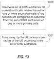
- Further aspects of the present disclosure are directed to receiving, at a UE configured for multiflow operation, a configuration for a secondary set of discontinuous reception (DRX) subframes for one or more secondary cells, wherein the secondary set for one or more secondary cells is related to a primary set of DRX subframes of a primary cell, and tuning away, by the UE, one or more radios of the UE according to the secondary set of DRX subframes.
- DRX discontinuous reception
- a method of wireless communication by a multi-uplink capable UE includes preparing, at the UE, a plurality of uplink control channel transmissions for a plurality of nodes in multiflow communication with the UE over a plurality of CC, the plurality of nodes comprising a first node having a primary cell (PCell) for communicating with the UE and a second node having a secondary cell (SCell) for communicating with the UE, wherein each of the plurality of uplink control channel transmissions is configured for a corresponding node of the plurality of nodes on one of the plurality of CCs associated with the corresponding node, receiving a transmit power control command on the SCell of the plurality of nodes, wherein the transmit power control is received in a downlink control information message from the second node, and transmitting an uplink control channel transmission of the plurality of uplink control channel transmissions to the second node according to the transmit power control command.
- PCell primary cell
- SCell secondary cell
- a method of wireless communication includes preparing, at a UE, a plurality of uplink control channel transmissions and one or more uplink shared channel transmissions for multiflow uplink transmission to two or more non co-located nodes, determining, at the UE, that the UE is power limited, and applying a power allocation of the UE according to a prioritization in which application of the power allocation across the plurality of uplink control signal transmissions is prioritized over application of the power allocation the one or more uplink shared channel transmissions.
- a method of wireless communication includes reporting, by a UE, a multiple uplink capability of the UE and receiving configuration for the UE to perform multiflow uplink transmission for one or more non co-located nodes belonging to one or more TAGs, wherein each of the one or more non co-located nodes belongs to a separate one of the one or more TAGs.
- a method of wireless communication includes generating, by a UE, a plurality of SRS for each of a plurality of non co-located nodes in multiflow communication with the UE, determining, at the UE, that the UE has a single uplink capability, identifying a cell ID for each of the plurality of non co-located nodes, and prioritizing transmission of the plurality of SRS according to the cell ID in a subframe where collision of two or more of the plurality of SRS is detected.
- a method of wireless communication includes preparing a power headroom report, at a UE configured for multiflow operation with a plurality of non co-located nodes, for a booster or secondary node of the plurality of non co-located nodes, wherein the power headroom report includes a maximum allowable transmission power of the UE for the booster or secondary node minus a first transmit power allocated for uplink control signal transmissions to the booster or secondary node and minus a second transmit power allocated for uplink shared channel transmissions, and transmitting the power headroom report to the booster or secondary node.
- a method of wireless communication includes receiving, at a booster or secondary node of a plurality of non co-located nodes, a power headroom report from a serviced UE configured for multiflow operation with the plurality of non co-located nodes, wherein the power headroom report includes a maximum allowable transmission power of the UE minus a first transmit power allocated for uplink control signal transmissions to the booster or secondary node and minus a second transmit power allocated for uplink shared channel transmissions, and scheduling, at the booster or secondary node, communication with the serviced UE based on the power headroom report.
- a method of wireless communication includes receiving, at a UE configured for multiflow operation with a plurality of non co-located nodes, a configuration for a secondary set of DRX subframes for one or more secondary cells of the plurality of non co-located nodes, wherein the secondary set of DRX subframes for one or more secondary cells is separate from a primary set of DRX subframes of a primary cell of the plurality of non co-located nodes, and tuning away, by the UE, one or more radios of the UE according to the secondary set of DRX subframes.
- an apparatus configured for wireless communication includes means for preparing, at the UE, a plurality of uplink control channel transmissions for a plurality of nodes in multiflow communication with the UE over a plurality of CC, the plurality of nodes comprising a first node having a primary cell (PCell) for communicating with the UE and a second node having a secondary cell (SCell) for communicating with the UE, wherein each of the plurality of uplink control channel transmissions is configured for a corresponding node of the plurality of nodes on one of the plurality of CCs associated with the corresponding node, means for receiving a transmit power control command on the SCell of the plurality of nodes, wherein the transmit power control is received in a downlink control information message from the second node, and means for transmitting an uplink control channel transmission of the plurality of uplink control channel transmissions to the second node according to the transmit power control command.
- PCell primary cell
- SCell secondary cell
- an apparatus configured for wireless communication includes means for preparing, at a UE, a plurality of uplink control channel transmissions and one or more uplink shared channel transmissions for multiflow uplink transmission to two or more non co-located nodes, means for determining, at the UE, that the UE is power limited, and means for applying a power allocation of the UE according to a prioritization in which application of the power allocation across the plurality of uplink control signal transmissions is prioritized over application of the power allocation the one or more uplink shared channel transmissions.
- an apparatus configured for wireless communication includes means for reporting, by a UE, a multiple uplink capability of the UE and means for receiving configuration for the UE to perform multiflow uplink transmission for one or more non co-located nodes belonging to one or more TAGs, wherein each of the one or more non co-located nodes belongs to a separate one of the one or more TAGs.
- an apparatus configured for wireless communication includes means for generating, by a UE, a plurality of SRS for each of a plurality of non co-located nodes in multiflow communication with the UE, means for determining, at the UE, that the UE has a single uplink capability, means for identifying a cell ID for each of the plurality of non co-located nodes, and means for prioritizing transmission of the plurality of SRS according to the cell ID in a subframe where collision of two or more of the plurality of SRS is detected.
- an apparatus configured for wireless communication includes means for preparing a power headroom report, at a UE configured for multiflow operation with a plurality of non co-located nodes, for a booster or secondary node of the plurality of non co-located nodes, wherein the power headroom report includes a maximum allowable transmission power of the UE for the booster or secondary node minus a first transmit power allocated for uplink control signal transmissions to the booster or secondary node and minus a second transmit power allocated for uplink shared channel transmissions, and means for transmitting the power headroom report to the booster or secondary node.
- an apparatus configured for wireless communication includes means for receiving, at a booster or secondary node of a plurality of non co-located nodes, a power headroom report from a serviced UE configured for multiflow operation with the plurality of non co-located nodes, wherein the power headroom report includes a maximum allowable transmission power of the UE minus a first transmit power allocated for uplink control signal transmissions to the booster or secondary node and minus a second transmit power allocated for uplink shared channel transmissions, and means for scheduling, at the booster or secondary node, communication with the serviced UE based on the power headroom report.
- an apparatus configured for wireless communication includes means for receiving, at a UE configured for multiflow operation with a plurality of non co-located nodes, a configuration for a secondary set of DRX subframes for one or more secondary cells of the plurality of non co-located nodes, wherein the secondary set of DRX subframes for one or more secondary cells is separate from a primary set of DRX subframes of a primary cell of the plurality of non co-located nodes, and means for tuning away, by the UE, one or more radios of the UE according to the secondary set of DRX subframes.
- a computer program product having a computer-readable medium having program code recorded thereon.
- This program code includes code to prepare, at the UE, a plurality of uplink control channel transmissions for a plurality of nodes in multiflow communication with the UE over a plurality of CC, the plurality of nodes comprising a first node having a primary cell (PCell) for communicating with the UE and a second node having a secondary cell (SCell) for communicating with the UE, wherein each of the plurality of uplink control channel transmissions is configured for a corresponding node of the plurality of nodes on one of the plurality of CCs associated with the corresponding node, code to receive a transmit power control command on the SCell of the plurality of nodes, wherein the transmit power control is received in a downlink control information message from the second node, and code to transmit an uplink control channel transmission of the plurality of uplink control channel transmissions to the second node according to the transmit power control command.
- PCell primary cell
- a computer program product having a computer-readable medium having program code recorded thereon.
- This program code includes code to prepare, at a UE, a plurality of uplink control channel transmissions and one or more uplink shared channel transmissions for multiflow uplink transmission to two or more non co-located nodes, code to determine, at the UE, that the UE is power limited, and code to apply a power allocation of the UE according to a prioritization in which application of the power allocation across the plurality of uplink control signal transmissions is prioritized over application of the power allocation the one or more uplink shared channel transmissions.
- a computer program product having a computer-readable medium having program code recorded thereon.
- This program code includes code to report, by a UE, a multiple uplink capability of the UE and code to receive configuration for the UE to perform multiflow uplink transmission for one or more non co-located nodes belonging to one or more TAGs, wherein each of the one or more non co-located nodes belongs to a separate one of the one or more TAGs.
- a computer program product having a computer-readable medium having program code recorded thereon.
- This program code includes code to generate, by a UE, a plurality of SRS for each of a plurality of non co-located nodes in multiflow communication with the UE, code to determine, at the UE, that the UE has a single uplink capability, code to identify a cell ID for each of the plurality of non co-located nodes, and code to prioritize transmission of the plurality of SRS according to the cell ID in a subframe where collision of two or more of the plurality of SRS is detected.
- a computer program product having a computer-readable medium having program code recorded thereon.
- This program code includes code to prepare a power headroom report, at a UE configured for multiflow operation with a plurality of non co-located nodes, for a booster or secondary node of the plurality of non co-located nodes, wherein the power headroom report includes a maximum allowable transmission power of the UE for the booster or secondary node minus a first transmit power allocated for uplink control signal transmissions to the booster or secondary node and minus a second transmit power allocated for uplink shared channel transmissions, and code to transmit the power headroom report to the booster or secondary node.
- a computer program product having a computer-readable medium having program code recorded thereon.
- This program code includes code to receive, at a booster or secondary node of a plurality of non co-located nodes, a power headroom report from a serviced UE configured for multiflow operation with the plurality of non co-located nodes, wherein the power headroom report includes a maximum allowable transmission power of the UE minus a first transmit power allocated for uplink control signal transmissions to the booster or secondary node and minus a second transmit power allocated for uplink shared channel transmissions, and code to schedule, at the booster or secondary node, communication with the serviced UE based on the power headroom report.
- a computer program product having a computer-readable medium having program code recorded thereon.
- This program code includes code to receive, at a UE configured for multiflow operation with a plurality of non co-located nodes, a configuration for a secondary set of DRX subframes for one or more secondary cells of the plurality of non co-located nodes, wherein the secondary set of DRX subframes for one or more secondary cells is separate from a primary set of DRX subframes of a primary cell of the plurality of non co-located nodes, and code to tune away, by the UE, one or more radios of the UE according to the secondary set of DRX subframes.
- an apparatus includes at least one processor and a memory coupled to the processor.
- the processor is configured to prepare, at the UE, a plurality of uplink control channel transmissions for a plurality of nodes in multiflow communication with the UE over a plurality of CC, the plurality of nodes comprising a first node having a primary cell (PCell) for communicating with the UE and a second node having a secondary cell (SCell) for communicating with the UE, wherein each of the plurality of uplink control channel transmissions is configured for a corresponding node of the plurality of nodes on one of the plurality of CCs associated with the corresponding node, to receive a transmit power control command on the SCell of the plurality of nodes, wherein the transmit power control is received in a downlink control information message from the second node, and to transmit an uplink control channel transmission of the plurality of uplink control channel transmissions to the second node according to the transmit power control command.
- PCell primary cell
- SCell secondary cell
- an apparatus includes at least one processor and a memory coupled to the processor.
- the processor is configured to prepare, at a UE, a plurality of uplink control channel transmissions and one or more uplink shared channel transmissions for multiflow uplink transmission to two or more non co-located nodes, to determine, at the UE, that the UE is power limited, and to apply a power allocation of the UE according to a prioritization in which application of the power allocation across the plurality of uplink control signal transmissions is prioritized over application of the power allocation the one or more uplink shared channel transmissions.
- an apparatus includes at least one processor and a memory coupled to the processor.
- the processor is configured to report, by a UE, a multiple uplink capability of the UE and to receive configuration for the UE to perform multiflow uplink transmission for one or more non co-located nodes belonging to one or more TAGs, wherein each of the one or more non co-located nodes belongs to a separate one of the one or more TAGs.
- an apparatus includes at least one processor and a memory coupled to the processor.
- the processor is configured to generate, by a UE, a plurality of SRS for each of a plurality of non co-located nodes in multiflow communication with the UE, to determine, at the UE, that the UE has a single uplink capability, to identify a cell ID for each of the plurality of non co-located nodes, and to prioritize transmission of the plurality of SRS according to the cell ID in a subframe where collision of two or more of the plurality of SRS is detected.
- an apparatus includes at least one processor and a memory coupled to the processor.
- the processor is configured to prepare a power headroom report, at a UE configured for multiflow operation with a plurality of non co-located nodes, for a booster or secondary node of the plurality of non co-located nodes, wherein the power headroom report includes a maximum allowable transmission power of the UE for the booster or secondary node minus a first transmit power allocated for uplink control signal transmissions to the booster or secondary node and minus a second transmit power allocated for uplink shared channel transmissions, and to transmit the power headroom report to the booster or secondary node.
- an apparatus includes at least one processor and a memory coupled to the processor.
- the processor is configured to receive, at a booster or secondary node of a plurality of non co-located nodes, a power headroom report from a serviced UE configured for multiflow operation with the plurality of non co-located nodes, wherein the power headroom report includes a maximum allowable transmission power of the UE minus a first transmit power allocated for uplink control signal transmissions to the booster or secondary node and minus a second transmit power allocated for uplink shared channel transmissions, and to schedule, at the booster or secondary node, communication with the serviced UE based on the power headroom report.
- an apparatus includes at least one processor and a memory coupled to the processor.
- the processor is configured to receive, at a UE configured for multiflow operation with a plurality of non co-located nodes, a configuration for a secondary set of DRX subframes for one or more secondary cells of the plurality of non co-located nodes, wherein the secondary set of DRX subframes for one or more secondary cells is separate from a primary set of DRX subframes of a primary cell of the plurality of non co-located nodes, and to tune away, by the UE, one or more radios of the UE according to the secondary set of DRX subframes.
- a CDMA network may implement a radio technology, such as Universal Terrestrial Radio Access (UTRA), Telecommunications Industry Association's (TIA's) CDMA2000 ® , and the like.
- UTRA Universal Terrestrial Radio Access
- TIA's Telecommunications Industry Association's
- the UTRA technology includes Wideband CDMA (WCDMA) and other variants of CDMA.
- WCDMA Wideband CDMA
- the CDMA2000 ® technology includes the IS-2000, IS-95 and IS-856 standards from the Electronics Industry Alliance (EIA) and TIA.
- a TDMA network may implement a radio technology, such as Global System for Mobile Communications (GSM).
- GSM Global System for Mobile Communications
- An OFDMA network may implement a radio technology, such as Evolved UTRA (E-UTRA), Ultra Mobile Broadband (UMB), IEEE 802.11 (Wi-Fi), IEEE 802.16 (WiMAX), IEEE 802.20, Flash-OFDMA, and the like.
- E-UTRA Evolved UTRA
- UMB Ultra Mobile Broadband
- Wi-Fi IEEE 802.11
- WiMAX IEEE 802.16
- Flash-OFDMA Flash-OFDMA
- the UTRA and E-UTRA technologies are part of Universal Mobile Telecommunication System (UMTS).
- 3GPP Long Term Evolution (LTE) and LTE-Advanced (LTE-A) are newer releases of the UMTS that use E-UTRA.
- UTRA, E-UTRA, UMTS, LTE, LTE-A and GSM are described in documents from an organization called the "3rd Generation Partnership Project" (3GPP).
- CDMA2000 ® and UMB are described in documents from an organization called the "3rd Generation Partnership Project 2" (3GPP2).
- 3GPP2 3rd Generation Partnership Project 2
- the techniques described herein may be used for the wireless networks and radio access technologies mentioned above, as well as other wireless networks and radio access technologies.
- LTE or LTE-A (together referred to in the alternative as "LTE/-A”) and use such LTE/-A terminology in much of the description below.
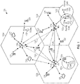
- FIG. 1 shows a wireless network 100 for communication, which may be an LTE-A network.
- the wireless network 100 includes a number of evolved node Bs (eNBs) 110 and other network entities.
- An eNB may be a station that communicates with the UEs and may also be referred to as a base station, a node B, an access point, and the like.
- Each eNB 110 may provide communication coverage for a particular geographic area.
- the term "cell" can refer to this particular geographic coverage area of an eNB and/or an eNB subsystem serving the coverage area, depending on the context in which the term is used.
- An eNB may provide communication coverage for a macro cell, a pico cell, a femto cell, and/or other types of cell.
- a macro cell generally covers a relatively large geographic area (e.g., several kilometers in radius) and may allow unrestricted access by UEs with service subscriptions with the network provider.
- a pico cell would generally cover a relatively smaller geographic area and may allow unrestricted access by UEs with service subscriptions with the network provider.
- a femto cell would also generally cover a relatively small geographic area (e.g., a home) and, in addition to unrestricted access, may also provide restricted access by UEs having an association with the femto cell (e.g., UEs in a closed subscriber group (CSG), UEs for users in the home, and the like).
- An eNB for a macro cell may be referred to as a macro eNB.
- An eNB for a pico cell may be referred to as a pico eNB.
- an eNB for a femto cell may be referred to as a femto eNB or a home eNB.
- a femto eNB or a home eNB.
- the eNBs 110a, 110b and 110c are macro eNBs for the macro cells 102a, 102b and 102c, respectively.
- the eNB 110x is a pico eNB for a pico cell 102x.
- the eNBs 110y and 110z are femto eNBs for the femto cells 102y and 102z, respectively.
- An eNB may support one or multiple (e.g., two, three, four, and the like) cells.
- the wireless network 100 also includes relay stations.
- a relay station is a station that receives a transmission of data and/or other information from an upstream station (e.g., an eNB, a UE, or the like) and sends a transmission of the data and/or other information to a downstream station (e.g., another UE, another eNB, or the like).
- a relay station may also be a UE that relays transmissions for other UEs.
- a relay station 110r may communicate with the eNB 110a and a UE 120r, in which the relay station 110r acts as a relay between the two network elements (the eNB 110a and the UE 120r) in order to facilitate communication between them.
- a relay station may also be referred to as a relay eNB, a relay, and the like.
- the wireless network 100 may support synchronous or asynchronous operation.
- the eNBs may have similar frame timing, and transmissions from different eNBs may be approximately aligned in time.
- the eNBs may have different frame timing, and transmissions from different eNBs may not be aligned in time.
- the UEs 120 are dispersed throughout the wireless network 100, and each UE may be stationary or mobile.
- a UE may also be referred to as a terminal, a mobile station, a subscriber unit, a station, or the like.
- a UE may be a cellular phone, a personal digital assistant (PDA), a wireless modem, a wireless communication device, a handheld device, a tablet computer, a laptop computer, a cordless phone, a wireless local loop (WLL) station, or the like.
- PDA personal digital assistant
- WLL wireless local loop
- a UE may be able to communicate with macro eNBs, pico eNBs, femto eNBs, relays, and the like.
- a solid line with double arrows indicates desired transmissions between a UE and a serving eNB, which is an eNB designated to serve the UE on the downlink and/or uplink.
- a dashed line with double arrows indicates interfering transmissions between a UE and an eNB.
- LTE/-A utilizes orthogonal frequency division multiplexing (OFDM) on the downlink and single-carrier frequency division multiplexing (SC-FDM) on the uplink.
- OFDM and SC-FDM partition the system bandwidth into multiple (K) orthogonal subcarriers, which are also commonly referred to as tones, bins, or the like.
- K orthogonal subcarriers
- Each subcarrier may be modulated with data.
- modulation symbols are sent in the frequency domain with OFDM and in the time domain with SC-FDM.
- the spacing between adjacent subcarriers may be fixed, and the total number of subcarriers (K) may be dependent on the system bandwidth.
- K may be equal to 72, 180, 300, 600, 900, and 1200 for a corresponding system bandwidth of 1.4, 3, 5, 10, 15, or 20 megahertz (MHz), respectively.
- the system bandwidth may also be partitioned into sub-bands.
- a sub-band may cover 1.08 MHz, and there may be 1, 2, 4, 8 or 16 sub-bands for a corresponding system bandwidth of 1.4, 3, 5, 10, 15, or 20MHz, respectively.
- Wireless network 100 uses the diverse set of eNBs 110 (i.e., macro eNBs, pico eNBs, femto eNBs, and relays) to improve the spectral efficiency of the system per unit area. Because the wireless network 100 uses such different eNBs for its spectral coverage, it may also be referred to as a heterogeneous network.
- the macro eNBs 110a-c are usually carefully planned and placed by the provider of the wireless network 100.
- the macro eNBs 110a-c generally transmit at high power levels (e.g., 5 W - 40 W).
- the pico eNB 110x and the relay station 110r which generally transmit at substantially lower power levels (e.g., 100 mW - 2 W), may be deployed in a relatively unplanned manner to eliminate coverage holes in the coverage area provided by the macro eNBs 110a-c and improve capacity in the hot spots.
- the femto eNBs 110y-z which are typically deployed independently from the wireless network 100 may, nonetheless, be incorporated into the coverage area of the wireless network 100 either as a potential access point to the wireless network 100, if authorized by their administrator(s), or at least as an active and aware eNB that may communicate with the other eNBs 110 of the wireless network 100 to perform resource coordination and coordination of interference management.
- the femto eNBs 110y-z typically also transmit at substantially lower power levels (e.g., 100 mW - 2 W) than the macro eNBs 110a-c.
- each UE In operation of a heterogeneous network, such as the wireless network 100, each UE is usually served by the eNB 110 with the better signal quality, while the unwanted signals received from the other eNBs 110 are treated as interference. While such operational principals can lead to significantly sub-optimal performance, gains in network performance are realized in the wireless network 100 by using intelligent resource coordination among the eNBs 110, better server selection strategies, and more advanced techniques for efficient interference management.
- a pico eNB such as the pico eNB 110x, is characterized by a substantially lower transmit power when compared with a macro eNB, such as the macro eNBs 110a-c.
- a pico eNB will also usually be placed around a network, such as the wireless network 100, in an ad hoc manner. Because of this unplanned deployment, wireless networks with pico eNB placements, such as the wireless network 100, can be expected to have large areas with low signal to interference conditions, which can make for a more challenging RF environment for control channel transmissions to UEs on the edge of a coverage area or cell (a "cell-edge" UE).
- the potentially large disparity (e.g., approximately 20 dB) between the transmit power levels of the macro eNBs 110a-c and the pico eNB 110x implies that, in a mixed deployment, the downlink coverage area of the pico eNB 110x will be much smaller than that of the macro eNBs 110a-c.
- the signal strength of the uplink signal is governed by the UE, and, thus, will be similar when received by any type of the eNBs 110.
- uplink handoff boundaries will be determined based on channel gains. This can lead to a mismatch between downlink handover boundaries and uplink handover boundaries. Without additional network accommodations, the mismatch would make the server selection or the association of UE to eNB more difficult in the wireless network 100 than in a macro eNB-only homogeneous network, where the downlink and uplink handover boundaries are more closely matched.
- the usefulness of mixed eNB deployment of heterogeneous networks will be greatly diminished.
- the larger coverage area of the higher powered macro eNBs, such as the macro eNBs 110a-c limits the benefits of splitting the cell coverage with the pico eNBs, such as the pico eNB 110x, because, the higher downlink received signal strength of the macro eNBs 110a-c will attract all of the available UEs, while the pico eNB 110x may not be serving any UE because of its much weaker downlink transmission power.
- the macro eNBs 110a-c will likely not have sufficient resources to efficiently serve those UEs. Therefore, the wireless network 100 will attempt to actively balance the load between the macro eNBs 110a-c and the pico eNB 110x by expanding the coverage area of the pico eNB 110x. This concept is referred to as cell range expansion (CRE).
- CRE cell range expansion
- the wireless network 100 achieves CRE by changing the manner in which server selection is determined. Instead of basing server selection on downlink received signal strength, selection is based more on the quality of the downlink signal. In one such quality-based determination, server selection may be based on determining the eNB that offers the minimum path loss to the UE. Additionally, the wireless network 100 provides a fixed partitioning of resources between the macro eNBs 110a-c and the pico eNB 110x. However, even with this active balancing of load, downlink interference from the macro eNBs 110a-c should be mitigated for the UEs served by the pico eNBs, such as the pico eNB 110x. This can be accomplished by various methods, including interference cancellation at the UE, resource coordination among the eNBs 110, or the like.
- the pico eNB 110x engages in control channel and data channel interference coordination with the dominant interfering ones of the macro eNBs 110a-c.
- ICIC inter-cell interference coordination
- One ICIC mechanism is adaptive resource partitioning. Adaptive resource partitioning assigns subframes to certain eNBs. In subframes assigned to a first eNB, neighbor eNBs do not transmit. Thus, interference experienced by a UE served by the first eNB is reduced. Subframe assignment may be performed on both the uplink and downlink channels.
- subframes may be allocated between three classes of subframes: protected subframes (U subframes), prohibited subframes (N subframes), and common subframes (C subframes).
- Protected subframes are assigned to a first eNB for use exclusively by the first eNB
- Protected subframes may also be referred to as "clean" subframes based on the lack of interference from neighboring eNBs.
- Prohibited subframes are subframes assigned to a neighbor eNB, and the first eNB is prohibited from transmitting data during the prohibited subframes.
- a prohibited subframe of the first eNB may correspond to a protected subframe of a second interfering eNB
- the first eNB is the only eNB transmitting data during the first eNB's protected subframe.
- Common subframes may be used for data transmission by multiple eNBs. Common subframes may also be referred to as "unclean" subframes because of the possibility of interference from other eNBs.
- At least one protected subframe is statically assigned per period. In some cases only one protected subframe is statically assigned. For example, if a period is 8 milliseconds, one protected subframe may be statically assigned to an eNB during every 8 milliseconds. Other subframes may be dynamically allocated.
- Adaptive resource partitioning information allows the non-statically assigned subframes to be dynamically allocated. Any of protected, prohibited, or common subframes may be dynamically allocated (AU, AN, AC subframes, respectively).
- the dynamic assignments may change quickly, such as, for example, every one hundred milliseconds or less.
- Heterogeneous networks may have eNBs of different power classes. For example, three power classes may be defined, in decreasing power class, as macro eNBs, pico eNBs, and femto eNBs.
- macro eNBs, pico eNBs, and femto eNBs are in a co-channel deployment, the power spectral density (PSD) of the macro eNB (aggressor eNB) may be larger than the PSD of the pico eNB and the femto eNB (victim eNBs) creating large amounts of interference with the pico eNB and the femto eNB.
- PSD power spectral density
- Protected subframes may be used to reduce or minimize interference with the pico eNBs and femto eNBs. That is, a protected subframe may be scheduled for the victim eNB to correspond with a prohibited subframe on the aggressor eNB
- a UE may operate in a dominant interference scenario in which the UE may observe high interference from one or more interfering eNBs.
- a dominant interference scenario may occur due to restricted association.
- the UE 120y may be close to the femto eNB 110y and may have high received power for the eNB 110y.
- the UE 120y may not be able to access the femto eNB 110y due to restricted association and may then connect to the macro eNB 110c (as shown in FIG. 1 ) or to the femto eNB 110z also with lower received power (not shown in FIG. 1 ).
- the UE 120y may then observe high interference from the femto eNB 110y on the downlink and may also cause high interference to the eNB 110y on the uplink.
- the eNB 110c and the femto eNB 110y may communicate over the backhaul 134 to negotiate resources.
- the femto eNB 110y agrees to cease transmission on one of its channel resources, such that the UE 120y will not experience as much interference from the femto eNB 110y as it communicates with the eNB 110c over that same channel.
- timing delays of downlink signals may also be observed by the UEs, even in synchronous systems, because of the differing distances between the UEs and the multiple eNBs.
- the eNBs in a synchronous system are presumptively synchronized across the system. However, for example, considering a UE that is a distance of 5 km from the macro eNB, the propagation delay of any downlink signals received from that macro eNB would be delayed approximately 16.67 ⁇ s (5 km ⁇ 3 ⁇ 10 8 , i.e., the speed of light, 'c'). Comparing that downlink signal from the macro eNB to the downlink signal from a much closer femto eNB, the timing difference could approach the level of a time-to-live (TTL) error.
- TTL time-to-live
- Interference cancellation often uses cross correlation properties between a combination of multiple versions of the same signal. By combining multiple copies of the same signal, interference may be more easily identified because, while there will likely be interference on each copy of the signal, it will likely not be in the same location. Using the cross correlation of the combined signals, the actual signal portion may be determined and distinguished from the interference, thus, allowing the interference to be canceled.
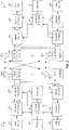
- FIG. 2 shows a block diagram of a design of a base station/eNB 110 and a UE 120, which may be one of the base stations/eNBs and one of the UEs in FIG. 1 .
- the eNB 110 may be the macro eNB 110c in FIG. 1
- the UE 120 may be the UE 120y.
- the eNB 110 may also be a base station of some other type.
- the eNB 110 may be equipped with antennas 234a through 234t, and the UE 120 may be equipped with antennas 252a through 252r.
- a transmit processor 220 may receive data from a data source 212 and control information from a controller/processor 240.
- the control information may be for the PBCH, PCFICH, PHICH, PDCCH, etc.
- the data may be for the PDSCH, etc.
- the transmit processor 220 may process (e.g., encode and symbol map) the data and control information to obtain data symbols and control symbols, respectively.
- the transmit processor 220 may also generate reference symbols, e.g., for the PSS, SSS, and cell-specific reference signal.
- a transmit (TX) multiple-input multiple-output (MIMO) processor 230 may perform spatial processing (e.g., precoding) on the data symbols, the control symbols, and/or the reference symbols, if applicable, and may provide output symbol streams to the modulators (MODs) 232a through 232t.
- Each modulator 232 may process a respective output symbol stream (e.g., for OFDM, etc.) to obtain an output sample stream.
- Each modulator 232 may further process (e.g., convert to analog, amplify, filter, and upconvert) the output sample stream to obtain a downlink signal.
- Downlink signals from modulators 232a through 232t may be transmitted via the antennas 234a through 234t, respectively.
- the antennas 252a through 252r may receive the downlink signals from the eNB 110 and may provide received signals to the demodulators (DEMODs) 254a through 254r, respectively.
- Each demodulator 254 may condition (e.g., filter, amplify, downconvert, and digitize) a respective received signal to obtain input samples.
- Each demodulator 254 may further process the input samples (e.g., for OFDM, etc.) to obtain received symbols.
- a MIMO detector 256 may obtain received symbols from all the demodulators 254a through 254r, perform MIMO detection on the received symbols if applicable, and provide detected symbols.
- a receive processor 258 may process (e.g., demodulate, deinterleave, and decode) the detected symbols, provide decoded data for the UE 120 to a data sink 260, and provide decoded control information to a controller/processor 280.
- a transmit processor 264 may receive and process data (e.g., for the PUSCH) from a data source 262 and control information (e.g., for the PUCCH) from the controller/processor 280.
- the transmit processor 264 may also generate reference symbols for a reference signal.
- the symbols from the transmit processor 264 may be precoded by a TX MIMO processor 266 if applicable, further processed by the demodulators 254a through 254r (e.g., for SC-FDM, etc.), and transmitted to the eNB 110.
- the uplink signals from the UE 120 may be received by the antennas 234, processed by the modulators 232, detected by a MIMO detector 236 if applicable, and further processed by a receive processor 238 to obtain decoded data and control information sent by the UE 120.
- the processor 238 may provide the decoded data to a data sink 239 and the decoded control information to the controller/processor 240.
- the controllers/processors 240 and 280 may direct the operation at the eNB 110 and the UE 120, respectively.
- the controller/processor 240 and/or other processors and modules at the eNB 110 may perform or direct the execution of various processes for the techniques described herein.
- the controllers/processor 280 and/or other processors and modules at the UE 120 may also perform or direct the execution of the functional blocks illustrated in FIGS. 5-13 , and/or other processes for the techniques described herein.
- the memories 242 and 282 may store data and program codes for the eNB 110 and the UE 120, respectively.
- a scheduler 244 may schedule UEs for data transmission on the downlink and/or uplink.
- LTE-Advanced UEs use spectrum up to 20 MHz bandwidths allocated in a carrier aggregation of up to a total of 100 MHz (5 component carriers) used for transmission in each direction.
- the uplink spectrum allocation may be smaller than the downlink allocation.
- the downlink may be assigned 100 MHz.
- Non-continuous CA occurs when multiple available component carriers are separated along the frequency band.
- continuous CA occurs when multiple available component carriers are adjacent to each other.
- Both non-continuous and continuous CA aggregate multiple LTE/component carriers to serve a single unit of LTE Advanced UE.
- Non-continuous CA supports data transmissions over multiple separated carriers across a large frequency range, propagation path loss, Doppler shift and other radio channel characteristics may vary a lot at different frequency bands.
- methods may be used to adaptively adjust coding, modulation and transmission power for different component carriers.
- eNodeB enhanced NodeB
- the effective coverage or supportable modulation and coding of each component carrier may be different.
- a UE When located at the cell edge, a UE may experience weak signals from its serving cell with more interference from neighboring cells. This combination may result in reduced performance for cell edge UEs.
- Advanced wireless networks may take advantage of unused capacity of neighboring cells by configuring network nodes and UEs to both receive on the downlink and transmit on the uplink to multiple cells or network nodes.
- a first node may be considered an anchor cell or the main serving cell, while the additional cells used for the multiflow operations may be considered booster cells.
- a UE conducting multiflow communication between a first node and a second node that are non co-located and/or have non-ideal backhaul communication links may communicate with each of the nodes over multiple component carriers (CCs).
- CCs component carriers
- a UE communicating with a node using multiple CCs will have a primary component carrier or cell (PCell) and additional secondary component carriers of cells (SCells).
- PCell primary component carrier or cell
- SCells additional secondary component carriers of cells
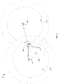
- FIG. 3 is a block diagram illustrating wireless network 30 configured for multiflow operation.
- UE 300 lies within the coverage area 304 of macro node 301.
- Macro node 301 also includes a cell range expansion (CRE) area defined between coverage area 304 and cell edge 305.
- CRE cell range expansion
- UE 300 also lies within the CRE area of macro node 302, defined between coverage area 307 and cell edge 307, and the CRE area of remote radio head (RRH) 303, defined between coverage area 308 and cell edge 309.
- RRH remote radio head
- UE 300 may receive separate downlink data from either or both of macro node 302 and RRH 303.
- the performance at UE 300 may even increase by taking advantage of additional resources available at macro node 302 and RRH 303.
- network nodes may be used with multiflow operations, such as eNBs, RRHs, WIFI TM access points, NodeBs, and the like.
- CA When operating on a network that supports for using CA, the CA standards provide for some PCell-specific functionalities. For example, advanced CA standards allow for uplink control in PUCCH only on the PCell. Thus, uplink control for all cells is conveyed on the PCell.
- This limitation in CA operation provides challenges to multiflow technology. In a multiflow environment, control for both bearer and packet level splitting should be conveyed to all nodes or cells involved in the downlink multiflow transmission. This may be relaxed in the case of packet splitting where there is a fiber connection among the multiple nodes participating in multiflow communication. Issues may also arise in uplink data transmission. Enabling the multiflow data transmission on uplink may be primarily related to the UE capability and timing advance (TA) grouping.
- TA timing advance
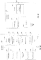
- UE 120 includes controller/processor 280 which controls the components and executes the software, firmware, or other logic that provide the features and functionality of UE 120.
- UE 120 may include components such as memory 282, transmitters 400, receivers 401, arithmetic unit 408, radio tuning control 409, power control 410, signal generator 411, and clock 412.
- Various software and logic may be stored on memory 282 that is executable by controller/processor 280 including multiflow operations 402, power control monitor 403, signal measurement 404, timing adjustment monitor 405, SRS generator 406, and tuning control 407, among others.
- Controller/processor 280 access memory 282 to execute these and other pieces of logic to operate the functionality of UE 120.
- a UE can generally be either multi-uplink capable or single-uplink capable.
- a multi-uplink capable UE has the capability to tune its multiple transmitters to different transmission frequencies simultaneously.
- radio tuning control 409 of UE 120 may be capable of tuning each of transmitters 400 to separate frequencies simultaneously. Otherwise, if radio tuning control 409 cannot provide such tuning, then UE 120 would only be able to transmit a single uplink transmission.
- Implementing multiflow communications with a UE for the uplink transmission process with the multiflow booster or secondary nodes may cause issues in various channels, signaling, and procedural operations, such as: power control (PC), pathloss (PL) estimation, timing adjustment grouping (TAG), sounding reference signal (SRS), random access (RA) processes, power headroom reporting (PHR), and discontinuous reception (DRX).
- PC power control
- PL pathloss
- TAG timing adjustment grouping
- SRS sounding reference signal
- RA random access
- PHR power headroom reporting
- DRX discontinuous reception
- FIG. 4B is a block diagram illustrating a booster node 40 configured according to one aspect of the present disclosure.
- Booster node 40 may include similar componentry as that included in eNB 110 ( FIG. 2 ), including controller processor 240, memory 242, and scheduler 244.
- Transmitters 413 and receivers 414 may include the individual components, such as transmit processor 220, TX MIMO processor 230, mod/demods 232a-t, antennas 234a-t, MIMO detector 236, and receiver processor 238 ( FIG.
- Booster node 40 may operate in multiflow networks through execution by controller/processor 240 of multiflow operations 415 in memory 242.
- the executing environment of multiflow operations 415 allow booster node 40 to receive uplink data and control information as a booster cell for a serviced UE and scheduling communications, through scheduler 244 under control of controller/processor 240, with the serviced UE based on the received control information and data.
- power control is defined separately for PUCCH and PUSCH for each CC. If multiple PUCCHs/PUSCHs are multiplexed on a single CC, separate power control for each of the channels should be provided.
- Transmit power control commands (TPC) in CA are provided in a downlink grant downlink control information (DCI) message of the PCell for PUCCH power control.
- DCI downlink grant downlink control information
- the TPC may be provided in an uplink grant DCI of the corresponding cell.
- the fields of the downlink grant of the booster or secondary node are utilized for some other purpose, e.g., for PUCCH Format 3 resource allocation.
- FIG. 5 is a functional block diagram illustrating example blocks executed to implement one aspect of the present disclosure.
- a UE participating in a multiflow operation prepares or compiles a PUCCH transmission for the booster or secondary node.
- controller/processor 280 would control signal generator 411 to prepare a PUCCH transmission targeted for the booster or secondary node.
- the combination of these components and acts would provide means for compiling, at a UE, a PUCCH transmission for a booster or secondary node in communication with the UE.
- the UE would receive a TPC command from the booster or secondary node included in a DCI message from the booster or secondary node.
- UE 120 receives a transmission from booster or secondary node through receivers 401.
- controller/processor 280 UE 120 decodes the signal as a downlink grant with a DCI message that includes a TPC command.
- the booster or secondary node may be configured, such as through RRC configuration to repurpose some of the existing bits of the DCI to accommodate a TPC command.
- the DCI bits are typically standardized to include information other than a TPC command. Accordingly, when multiflow operations cause such booster or secondary node to provide TPC commands or cause the UE to receive PUCCH on a booster or secondary node that was not provided for in the standard configuration of the DCI, various aspects of the present disclosure allow for re-purposing of the existing bits assigned for other purposes, to accommodate the new booster or secondary node provision of TPC commands or UE transmitting PUCCH to the booster or secondary node.
- the defined size of the DCI message may be increased in the standards to accommodate such TPC commands from booster or secondary nodes.
- the combination of these components and acts may provide means for receiving a transmit power control command from the booster or secondary node, wherein the transmit power control is received in a downlink control information message.
- the UE transmits the PUCCH to the booster or secondary node according to the TPC received.
- controller/processor 280 executes power control monitor 403 in memory 282.
- the executing environment of power control monitor 403 uses the TPC command received from the booster or secondary node to adjust the transmit power of the PUCCH transmission through power controller 410, under control of controller/processor 280.
- the combination of these components and acts may provide means for transmitting the PUCCH to the booster or secondary node according to the transmit power control command.
- FIG. 6 is a functional block diagram illustrating example blocks executed to implement one aspect of the present disclosure.
- the UE schedules a number of PUCCH and PUSCH transmissions for multiflow operation.
- Executing multiflow operations 402 in memory 282, controller/processor 280 operates to generate multiple PUCCH and PUSCH transmissions targeted at the nodes participating in the multiflow operation.
- the combination of these components and acts may provide means for scheduling, at a UE, a plurality of PUCCH transmissions and one or more PUSCH transmissions for multiflow uplink transmission.
- UE 120 determines that its maximum available power may not be sufficient to transmit all of the PUCCH and PUSCH transmissions that have been scheduled.
- the combination of these components and acts may provide means for determining, at the UE, that the UE is power limited.
- the UE prioritizes a power allocation across the multiple PUCCH and PUSCH transmissions scheduled for multiflow operation.
- Various numbers of prioritization schemes may be employed by the UE in order to prioritize or allocate the available UE power.
- prioritization of the multiple PUCCHs may give the highest priority to PUCCHs targeted for the anchor node or, alternatively, the UE may scale across PUCCHs, either using a uniform or weighted scaling (e.g., weighting more for anchor node PUCCH).
- prioritization of multiple PUSCHs may differentiate between the PUSCH that are carrying uplink control information and PUSCH that are carrying only data, in which PUSCH that carry uplink control information may receive a higher priority than pure data PUSCH transmissions.
- the UE may again give the highest priority to the anchor node or scale, uniformly or weighted, across PUSCHs.
- Controller/processor 280 running both multiflow operations 402 and power control monitor 403 creates an operating environment in which the prioritization schemes within multiflow operation 402 works with power control monitor 403 to control power controller 410 to adjust the power accordingly across the various PUCCH and PUSCH transmissions scheduled for multiflow.
- power controller 410 applies the appropriate power to transmitters 400 while signal generator 411 prepares the PUCCH and PUSCH signals for transmission and radio tuning control 409, all under control of controller/processor 280, tunes transmitters 400 to the appropriate frequencies for transmission of the PUCCH and PUSCH.
- the combination of these components and acts may provide means for prioritizing a power allocation of the UE across the plurality of PUCCH transmissions and means for prioritizing the power allocation of the UE across the one or more PUSCH transmissions.
- path loss estimation of a cell may be estimated either based on the corresponding downlink CC of the given cell, or the PCell, depending on which timing adjustment grouping (TAG) the serving cell belongs to.
- TAG timing adjustment grouping
- controller/processor 280 executes signal measurement 404 functionality in memory 282 to enable measurement and determination of the path loss estimate from signals received through receivers 401.
- the same mechanism can be used for multiflow in cases where PUCCH/PUSCH are transmitted on the corresponding (separate) carriers of the corresponding nodes. Such cases may only be implemented using multi-uplink capable UEs.
- the reference cell for path loss estimation may be different. Although transmitted on the same CC, the uplink signal will have to reach different nodes.
- the current specification is applicable as those channels would be linked to the separate cells (although transmitted on the same carrier).
- multiflow operations may connect a UE with base stations or nodes that are not in the same location or even within the same cell area, it is possible that the different cells with which the UE are communicating may not have the same timing adjustment (TA) and, therefore, not belong to the same TA grouping (TAG).
- TA timing adjustment
- TAG TA grouping
- Multiflow with the cells in different TAGs for a single uplink CC-capable UE may not be feasible, at least not with reasonable efficiency.
- An exception may also exist for fiber connected nodes or collocated nodes with packet level splitting. In most scenarios, however, multiflow operation with cells belonging to different TAGs will be configured for multi-uplink-capable UEs.
- FIG. 7 is a functional block diagram illustrating example blocks executed to implement one aspect of the present disclosure.
- a UE reports a multiple uplink capability of a UE.
- controller/processor 280 operates with radio tuning control 409 and will know whether radio tuning control 409 is capable of tuning transmitters 400 to different frequencies for simultaneous uplink transmission.
- UE 120 would report such a multi-uplink capability by sending a signal, generated by signal generator 411, under control of controller/processor 280, and transmitted by transmitters 400.
- the combination of these components and acts may provide means for reporting a multiple uplink capability of the UE.
- the UE receives configuration for the UE to perform multiflow uplink transmission for one or more cells regardless of a TAG to which the one or more cells belongs.
- UE 120 may, under control of controller/processor 280, execute timing adjustment monitor 405 in memory 282. Timing adjustment monitor 405 monitors the TAG for each of the cells.
- UE 120 receives control signaling over receivers 401 with configuration information that allows multiflow operation for UE 120 with cells having different TAGs.
- the combination of these components and acts may provide means for receiving configuration for the UE to perform multiflow uplink transmission for one or more CA cells regardless of a TAG to which the one or more cells belongs.
- FIG. 8 is a functional block diagram illustrating example blocks executed to implement one aspect of the present disclosure.
- a UE reports a single uplink capability of a UE.
- controller/processor 280 operates with radio tuning control 409 and will know whether radio tuning control 409 is capable of tuning transmitters 400 to different frequencies for simultaneous uplink transmission.
- UE 120 would report such a single uplink capability by sending a signal, generated by signal generator 411, under control of controller/processor 280, and transmitted by transmitters 400.
- the combination of these components and acts may provide means for reporting a single uplink capability of the UE.
- the UE receives configuration for the UE to perform multiflow uplink transmission for one or more cells that belong to the same TAG.
- UE 120 may, under control of controller/processor 280, execute timing adjustment monitor 405 in memory 282. Timing adjustment monitor 405 monitors the TAG for each of the cells.
- UE 120 receives control signaling over receivers 401 with configuration information that allows multiflow operation for UE 120 with cells of the same TAG.
- the combination of these components and acts may provide means for receiving configuration for the UE to perform multiflow uplink transmission for one or more CA cells belonging to the same TAG.
- SRS Sounding reference signals
- a UE may be configured with SRS parameters for trigger type 0 (periodic) and trigger type 1 (aperiodic) SRS on each serving cell.
- SRS parameters are generally serving cell specific and semi-statically configurable by higher layers.
- FIG. 9 is a functional block diagram illustrating example blocks executed to implement one aspect of the present disclosure.
- the UE determines that SRS are configured for multiple access nodes in a CA network with multiflow operations.
- multiflow operations 402, in memory 282, is executed along with SRS generator 406.
- Multiflow operations 402 includes triggers for scheduling multiple SRS targeted at the cells participating in the multiflow operation. The combination of these components and acts may provide means for determining, at a UE, that SRS are configured for a plurality of access nodes in network area configured for CA.
- the UE determines that it has a single-uplink capability.
- controller/processor 280 operates with radio tuning control 409 and will know whether or not radio tuning control 409 is capable of tuning transmitters 400 to different frequencies for simultaneous uplink transmission.
- the combination of these components and acts may provide means for determining, at the UE, that the UE has a single uplink capability.
- the UE identifies a cell identifier (ID) for each of the cells or nodes participating in the multiflow operation.
- UE 120 under control of controller/processor 280 analyzes signals received over receivers 401.
- the cell IDs are included in some of the transmissions from the participating nodes that are received at UE 120.
- UE 120 can identify the different cell IDs of each of the participating nodes.
- the combination of these components and acts may provide means for identifying a cell ID for each of the plurality of access nodes.
- the UE prioritizes transmission of the SRS according to the SRS when SRS collision is detected.
- Various prioritization schemes may be utilized by the UE in order to prioritize SRS transmission. For example, priority may be given to the lowest cell ID of the participating nodes. In many scenarios, the PCell will have the lowest cell ID and, thus, be provided the highest priority in an SRS collision instance.
- UE 120 under control of controller/processor 280 compares the cell IDs of the participating nodes for which scheduled SRS collide in a particular subframe using arithmetic unit 408, which may include arithmetic units such as comparators, adders, subtractors, and the like.
- controller/processor 280 Based on the comparison of cell IDs, controller/processor 280 triggers executing SRS generator 406 to generate an SRS using signal generator 411. Controller/processor 280 identifies the particular node which has received priority for SRS transmission, which will then be transmitted over transmitters 400, using power controller 410 and radio tuning control 409. A UE may transmit the highest priority SRS and drop the rest or may transmit subsequent SRS at a next highest priority. The combination of these components and acts may provide means for prioritizing transmission of the SRS according to the cell ID in a subframe where a collision is detected.
- random access is enabled on both PCell and SCell, using a PDCCH order for SCell random access.
- random access resources may be configured for each cell.
- a single TA can be supported.
- PHR power headroom report
- Type 2 currently applies to only PCell and where PUCCH and PUSCH are simultaneously transmitted.
- Type 2 PHR should also apply to the booster or secondary node as well. Accordingly, the various aspects of the present disclosure provide for configuration, such as through RRC messages, both a UE configured for CA and multiflow operation and participating booster or secondary node to transmit and receive Type 2 PHR.
- FIG. 10 is a functional block diagram illustrating example blocks executed to implement one aspect of the present disclosure.
- a UE configured for CA prepares a power headroom report for a booster or secondary node, where the power headroom report includes a maximum allowable transmission power of the UE minus a first transmit power allocated for PUCCH transmissions to the booster or secondary node and minus a second transmit power allocated for PUSCH transmissions to the booster or secondary node.
- Controller/processor 280 executes multiflow operations 402 in memory 282 to create a multiflow operations environment in which an operating power control monitor 403 calculates a Type 2 PHR for PUCCH and PUSCH that are prepared for transmission on booster or secondary node.
- the combination of these components and acts may provide means for preparing a power headroom report, at a UE configured for CA, for a booster or secondary node, wherein the power headroom report includes a maximum allowable transmission power of the UE for that cell minus a first transmit power allocated for PUCCH transmissions to the booster or secondary node and minus a second transmit power allocated for PUSCH transmissions.
- the UE transmits the PHR to the booster or secondary node.
- UE 120 may transmit the PHR generated by power control monitor 403 over transmitters 400.
- the combination of these components and acts may provide means for transmitting the power headroom report to the booster or secondary node.
- FIG. 11 is a functional block diagram illustrating example blocks executed to implement one aspect of the present disclosure from the SCell perspective.
- booster node 40 receives a power headroom report from a serviced UE, where the power headroom report includes a maximum allowable transmission power of the UE minus a first transmit power allocated for PUCCH transmissions to the secondary cell and minus a second transmit power allocated for PUSCH transmissions to the secondary cell.
- booster node 40 receives a PHR from a served UE over receivers 414.
- Controller/processor 240 which controls the componentry and executes the software, firmware, and other logic that defines the functionality and features of booster node 40, executes multiflow operations 415, stored in memory 242, which allows booster node 40 to understand receipt of PUCCH transmissions from a served UE where booster node 40 serves the UE as a secondary or booster node.
- the combination of these components and acts may provide means for receiving, at a booster or secondary node, a power headroom report from a serviced UE configured for CA, wherein the power headroom report includes a maximum allowable transmission power of the UE minus a first transmit power allocated for PUCCH transmissions to the secondary cell and minus a second transmit power allocated for PUSCH transmissions.
- the booster or secondary node may schedule communication with the serviced UE based on the received power headroom report.
- scheduler 244 schedules communication through transmitters 413 with the serviced UE, where the scheduling is performed by scheduler 244 using the power headroom report.
- the combination of these components and acts may provide means for scheduling, at the secondary cell, communication with the serviced UE based on the power headroom report.
- the power headroom formula may be adjusted to take into account additional channels.
- FIG. 12 is a functional block diagram illustrating example blocks executed to implement one aspect of the present disclosure.
- a UE prepares a power headroom report for a booster or secondary node, where the power headroom report includes a maximum allowable transmission power of the UE minus a first transmit power allocated for one or more PUSCH transmissions to the booster or secondary node.
- controller/processor 280 executes multiflow operations 402 in memory 282 to create a multiflow operations environment in which an operating power control monitor 403 calculates PHR that account for multiple PUSCH transmissions.
- the combination of these components and acts may provide means for preparing a power headroom report, at a UE configured for CA, for a anchor node and a booster or secondary node, wherein the power headroom report includes a maximum allowable transmission power of the UE for the corresponding cell minus a first transmit power allocated for one or more PUSCH transmissions.
- the UE transmits the PHR to both the anchor node and a booster or secondary nodes.
- UE 120 may transmit the PHR generated by power control monitor 403 over transmitters 400.
- the combination of these components and acts may provide means for transmitting the power headroom report to the anchor node and a booster or secondary nodes.
- SCell DRX may be configured to be separately from PCell DRX.
- SCell DRX may be configured to be an extended set of the PCell DRX subframes. That extended set may be a subset or a superset of the PCell DRX subframes depending on aspect of the disclosure being implemented. This configuration allows for more energy savings when downlink traffic is not so heavy.
- FIG. 13 is a functional block diagram illustrating example blocks executed to implement one aspect of the present disclosure.
- a UE configured for CA and multiflow operations receives a set of DRX subframes for a plurality of cells, where the set for one or more secondary cells of the network are configured separately from the set of DRX subframes of the primary cell.
- UE 120 receives through receivers 401 a set of DRX subframes.
- This set of DRX subframes includes a set of SCell DRX that are configured as an extension of the set of PCell DRX.
- the combination of these components and acts may provide means for receiving, at a UE configured for CA, a configuration for a secondary set of DRX subframes for one or more secondary cells, wherein the secondary set for one or more secondary cells is related to a primary set of DRX subframes of a primary cell.
- the UE tunes away its radios according to the received set of DRX subframes.
- controller/processor 280 executes tuning control 407 which uses the set of DRX subframes to determine when to activate radio tuning control 409, under control of controller/processor 280, to tune receivers 401 away from the current frequencies for DRX operation.
- the combination of these components and acts may provide means for tuning away, by the UE, one or more radios of the UE according to the secondary set of DRX subframes.
- the functional blocks and modules in FIGs. 5-13 may comprise processors, electronics devices, hardware devices, electronics components, logical circuits, memories, software codes, firmware codes, etc., or any combination thereof.
- DSP digital signal processor
- ASIC application specific integrated circuit
- FPGA field programmable gate array
- a general-purpose processor may be a microprocessor, but in the alternative, the processor may be any conventional processor, controller, microcontroller, or state machine.
- a processor may also be implemented as a combination of computing devices, e.g., a combination of a DSP and a microprocessor, a plurality of microprocessors, one or more microprocessors in conjunction with a DSP core, or any other such configuration.
- a software module may reside in RAM memory, flash memory, ROM memory, EPROM memory, EEPROM memory, registers, hard disk, a removable disk, a CD-ROM, or any other form of storage medium known in the art.
- An exemplary storage medium is coupled to the processor such that the processor can read information from, and write information to, the storage medium.
- the storage medium may be integral to the processor.
- the processor and the storage medium may reside in an ASIC.
- the ASIC may reside in a user terminal.
- the processor and the storage medium may reside as discrete components in a user terminal.
- the functions described may be implemented in hardware, software, firmware, or any combination thereof. If implemented in software, the functions may be stored on or transmitted over as one or more instructions or code on a computer-readable medium.
- Computer-readable media includes both computer storage media and communication media including any medium that facilitates transfer of a computer program from one place to another.
- a storage media may be any available media that can be accessed by a general purpose or special purpose computer.
- such computer-readable media can comprise RAM, ROM, EEPROM, CD-ROM or other optical disk storage, magnetic disk storage or other magnetic storage devices, or any other medium that can be used to carry or store desired program code means in the form of instructions or data structures and that can be accessed by a general-purpose or special-purpose computer, or a general-purpose or special-purpose processor.
- any connection is properly termed a computer-readable medium. For example, if the software is transmitted from a website, server, or other remote source using a coaxial cable, fiber optic cable, twisted pair, or digital subscriber line (DSL), then the coaxial cable, fiber optic cable, twisted pair, or are included in the definition of medium.
- DSL digital subscriber line
- Disk and disc includes compact disc (CD), laser disc, optical disc, digital versatile disc (DVD), floppy disk and blu-ray disc where disks usually reproduce data magnetically, while discs reproduce data optically with lasers. Combinations of the above should also be included within the scope of computer-readable media.
Landscapes
- Engineering & Computer Science (AREA)
- Signal Processing (AREA)
- Computer Networks & Wireless Communication (AREA)
- Mobile Radio Communication Systems (AREA)
Applications Claiming Priority (5)
| Application Number | Priority Date | Filing Date | Title |
|---|---|---|---|
| US201261725399P | 2012-11-12 | 2012-11-12 | |
| US201261725368P | 2012-11-12 | 2012-11-12 | |
| US14/076,931 US9509483B2 (en) | 2012-11-12 | 2013-11-11 | Uplink control and data transmission in multiflow-enabled networks |
| PCT/US2013/069631 WO2014075053A1 (en) | 2012-11-12 | 2013-11-12 | Uplink control and data transmission in multiflow-enabled networks |
| EP13796197.5A EP2918116A1 (en) | 2012-11-12 | 2013-11-12 | Uplink control and data transmission in multiflow-enabled networks |
Related Parent Applications (1)
| Application Number | Title | Priority Date | Filing Date |
|---|---|---|---|
| EP13796197.5A Division EP2918116A1 (en) | 2012-11-12 | 2013-11-12 | Uplink control and data transmission in multiflow-enabled networks |
Publications (1)
| Publication Number | Publication Date |
|---|---|
| EP4027711A1 true EP4027711A1 (en) | 2022-07-13 |
Family
ID=50681642
Family Applications (3)
| Application Number | Title | Priority Date | Filing Date |
|---|---|---|---|
| EP22159119.1A Pending EP4027711A1 (en) | 2012-11-12 | 2013-11-12 | Uplink control and data transmission in multiflow-enabled networks |
| EP13796197.5A Ceased EP2918116A1 (en) | 2012-11-12 | 2013-11-12 | Uplink control and data transmission in multiflow-enabled networks |
| EP13798811.9A Active EP2918035B1 (en) | 2012-11-12 | 2013-11-12 | Uplink transmission with carrier aggregation via multiple nodes |
Family Applications After (2)
| Application Number | Title | Priority Date | Filing Date |
|---|---|---|---|
| EP13796197.5A Ceased EP2918116A1 (en) | 2012-11-12 | 2013-11-12 | Uplink control and data transmission in multiflow-enabled networks |
| EP13798811.9A Active EP2918035B1 (en) | 2012-11-12 | 2013-11-12 | Uplink transmission with carrier aggregation via multiple nodes |
Country Status (10)
Families Citing this family (52)
| Publication number | Priority date | Publication date | Assignee | Title |
|---|---|---|---|---|
| WO2011155777A2 (ko) * | 2010-06-09 | 2011-12-15 | 엘지전자 주식회사 | 다중 반송파 지원 무선 통신 시스템에서 채널상태정보 송수신 방법 및 장치 |
| US9590791B2 (en) | 2012-11-12 | 2017-03-07 | Qualcomm Incorporated | Uplink transmission for carrier aggregation via multiple nodes |
| US9674886B2 (en) * | 2013-01-07 | 2017-06-06 | Lg Electronics Inc. | Method and apparatus for transmitting signals to a plurality of transmission points |
| EP2944133B1 (en) * | 2013-01-10 | 2022-09-07 | Telefonaktiebolaget LM Ericsson (publ) | A user equipment and a method for power control of uplink transmissions |
| US20140211647A1 (en) * | 2013-01-28 | 2014-07-31 | Innovative Sonic Corporation | Method and apparatus of small cell enhancement in a wireless communication system |
| KR102025385B1 (ko) * | 2013-02-26 | 2019-11-27 | 삼성전자주식회사 | 셀 내의 캐리어 집적 시스템에서 단말의 능력에 따른 제어 채널 전송 방법 및 장치 |
| KR102037388B1 (ko) * | 2013-04-05 | 2019-10-28 | 주식회사 팬택 | 무선 통신 시스템에서 단말의 잉여전력보고 전송방법 및 장치 |
| WO2014169459A1 (en) * | 2013-04-18 | 2014-10-23 | Telefonaktiebolaget L M Ericsson (Publ) | Method, ue and base station for transmitting periodic signal/periodic system information, and method and base station for forwarding periodic system information |
| CN105191448B (zh) * | 2013-04-19 | 2019-04-05 | Lg电子株式会社 | 在无线接入系统中的功率控制方法和设备 |
| EP3042536B1 (en) | 2013-09-04 | 2020-11-04 | LG Electronics, Inc. | Method and apparatus for controlling uplink power in wireless communication system |
| KR101611825B1 (ko) | 2013-11-08 | 2016-04-14 | 주식회사 케이티 | 상향링크 전송 전력을 제어하는 방법과 그 장치 |
| WO2015085561A1 (zh) * | 2013-12-13 | 2015-06-18 | 华为技术有限公司 | 调度方法、装置与系统 |
| CN104170341B (zh) * | 2014-01-29 | 2017-09-08 | 华为技术有限公司 | 一种数据传输方法、设备和系统 |
| CN106465289A (zh) * | 2014-05-08 | 2017-02-22 | 富士通株式会社 | 上行信道的功率控制方法、用户设备以及通信系统 |
| WO2015185256A1 (en) * | 2014-06-05 | 2015-12-10 | Sony Corporation | Communications device, infrastructure equipment, mobile communications network and methods |
| US10033505B2 (en) | 2014-07-31 | 2018-07-24 | Qualcomm Incorporated | Transmission of uplink control channels over an unlicensed radio frequency spectrum band |
| US9629094B2 (en) * | 2014-08-05 | 2017-04-18 | Qualcomm Incorporated | Techniques for prioritizing transmissions in multiple connectivity wireless communications |
| US10772051B2 (en) | 2014-08-15 | 2020-09-08 | Parallel Wireless, Inc. | Inter-cell interference mitigation |
| WO2016111527A1 (ko) * | 2015-01-05 | 2016-07-14 | 엘지전자 주식회사 | 제어 정보를 전송하는 방법 및 이를 위한 장치 |
| WO2016116165A1 (en) * | 2015-01-23 | 2016-07-28 | Nokia Solutions And Networks Oy | Method, apparatus and system for the configuration of an uplink control channel |
| US10159108B2 (en) * | 2015-04-10 | 2018-12-18 | Motorola Mobility Llc | DRX handling in LTE license assisted access operation |
| WO2017089473A1 (en) | 2015-11-24 | 2017-06-01 | Ipcom Gmbh & Co. Kg | Controlling uplink traffic received by multiple base stations |
| CN106817760B (zh) * | 2015-11-27 | 2021-11-02 | 中兴通讯股份有限公司 | 功率分配方法及装置 |
| CN107181514B (zh) * | 2016-03-11 | 2020-09-15 | 电信科学技术研究院 | 一种csi反馈方法、预编码方法及装置 |
| WO2017162813A1 (en) * | 2016-03-24 | 2017-09-28 | Telefonaktiebolaget Lm Ericsson (Publ) | Network node, method and computer program product for scheduling of paging messages with respect to discovery signal transmissions |
| US10219295B2 (en) * | 2016-05-13 | 2019-02-26 | Nokia Solutions And Networks Oy | Triggering of reference signals and control signaling |
| US20190182865A1 (en) * | 2016-08-12 | 2019-06-13 | Telefonaktiebolaget L M Ericsson (Publ) | Lbt parameters for uplink in unlicensed spectrum |
| US10574565B2 (en) | 2016-08-22 | 2020-02-25 | Qualcomm Incorporated | Event trigger for independent links |
| US20180097664A1 (en) * | 2016-09-30 | 2018-04-05 | Mediatek Inc. | Method And Apparatus For Handling Aperiodic Reference Signal In Mobile Communications |
| EP3376696B1 (en) * | 2017-03-13 | 2021-02-17 | Volkswagen Aktiengesellschaft | Apparatuses, methods and computer programs for estimating a multi-hop radio channel between a transmitter, one or more relay stations, and a receiver in a mobile communication system |
| KR102292994B1 (ko) * | 2017-03-23 | 2021-08-26 | 삼성전자 주식회사 | 무선 통신 시스템에서 타이밍 조정 방법 및 장치 |
| KR102423211B1 (ko) * | 2017-03-23 | 2022-07-20 | 가부시키가이샤 엔티티 도코모 | 유저단말 및 무선 통신 방법 |
| US10487564B2 (en) * | 2017-05-03 | 2019-11-26 | GM Global Technology Operations LLC | Door actuator adjustment for autonomous vehicles |
| US10560905B2 (en) | 2017-05-04 | 2020-02-11 | Samsung Electronics Co., Ltd. | Method and apparatus for transmitting power headroom information in a communication system |
| US10904908B2 (en) * | 2017-06-01 | 2021-01-26 | Qualcomm Incorporated | Grantless uplink transmission for eMTC-U |
| RU2732187C1 (ru) | 2017-06-15 | 2020-09-14 | Телефонактиеболагет Лм Эрикссон (Пабл) | Аппаратура, способы, компьютерные программы и компьютерные программные продукты для управления лучом |
| CN109429241A (zh) * | 2017-08-21 | 2019-03-05 | 中国移动通信集团公司 | 一种非连续接收的控制方法及终端 |
| US10959153B2 (en) | 2017-09-11 | 2021-03-23 | Qualcomm Incorporated | Techniques for multi-link aggregation signaling |
| US10314012B2 (en) | 2017-09-22 | 2019-06-04 | Qualcomm Incorporated | Carrier selection for position measurement |
| KR102289794B1 (ko) * | 2017-11-17 | 2021-08-12 | 차이나 아카데미 오브 텔레커뮤니케이션즈 테크놀로지 | 업링크 전력 제어 방법 및 이동 통신 단말 |
| WO2019125374A1 (en) * | 2017-12-18 | 2019-06-27 | Intel IP Corporation | Methods and apparatus to mitigate coexistence interference in a wireless network |
| US12225391B2 (en) | 2017-12-18 | 2025-02-11 | Intel Corporation | Methods and apparatus to mitigate coexistence interference in a wireless network |
| US11039465B2 (en) * | 2018-01-12 | 2021-06-15 | Qualcomm Incorporated | Uplink control information piggybacking in wireless systems |
| JP2019140465A (ja) * | 2018-02-07 | 2019-08-22 | パナソニック インテレクチュアル プロパティ コーポレーション オブ アメリカPanasonic Intellectual Property Corporation of America | 無線通信システム、無線通信制御方法、移動端末装置、基地局装置、及び、制御装置 |
| KR20200120701A (ko) * | 2018-02-12 | 2020-10-21 | 광동 오포 모바일 텔레커뮤니케이션즈 코포레이션 리미티드 | 채널 전송 방법, 장치 및 컴퓨터 기억 매체 |
| CN110474734B (zh) * | 2018-05-11 | 2022-02-08 | 华为技术有限公司 | 通信方法及装置 |
| CN113630229B (zh) | 2018-06-27 | 2022-11-25 | 华为技术有限公司 | 一种通信方法及装置 |
| CN110662285B (zh) * | 2018-06-29 | 2022-11-08 | 中兴通讯股份有限公司 | 定时调整信息的配置方法及装置 |
| EP4014618B1 (en) | 2019-08-16 | 2024-08-07 | Qualcomm Incorporated | Techniques for indicating uplink transmission capabilities in wireless communications |
| CN113973372B (zh) | 2020-07-24 | 2025-02-14 | 华为技术有限公司 | 一种信息发送和接收方法及装置 |
| WO2022064651A1 (ja) * | 2020-09-25 | 2022-03-31 | ソフトバンク株式会社 | ユーザ端末、基地局及び無線通信方法 |
| WO2024209488A1 (en) * | 2023-04-03 | 2024-10-10 | Centre Of Excellence In Wireless Technology | Method and signaling for enabling adaptation of subbands |
Citations (2)
| Publication number | Priority date | Publication date | Assignee | Title |
|---|---|---|---|---|
| US20120257569A1 (en) * | 2011-04-05 | 2012-10-11 | Samsung Electronics Co. Ltd. | Method and apparatus of configuring downlink timing and transmitting random access response in mobile communication system using carrier aggregation |
| US20120257513A1 (en) * | 2011-04-08 | 2012-10-11 | Sharp Laboratories Of America, Inc. | Devices for multi-group communications |
Family Cites Families (30)
| Publication number | Priority date | Publication date | Assignee | Title |
|---|---|---|---|---|
| US8150478B2 (en) | 2008-07-16 | 2012-04-03 | Marvell World Trade Ltd. | Uplink power control in aggregated spectrum systems |
| US20110143796A1 (en) * | 2008-07-30 | 2011-06-16 | Moon Il Lee | Method and apparatus of monitoring pdcch in wireless communication system |
| EP2394384B1 (en) | 2009-02-03 | 2019-01-30 | Nokia Solutions and Networks Oy | Apparatus and method of ack/nak bundling |
| TWI479924B (zh) * | 2009-08-02 | 2015-04-01 | Innovative Sonic Corp | 無線通訊系統之無線資源控制程序優化方法及通訊裝置 |
| US9014138B2 (en) | 2009-08-07 | 2015-04-21 | Blackberry Limited | System and method for a virtual carrier for multi-carrier and coordinated multi-point network operation |
| US20120188947A1 (en) * | 2009-10-02 | 2012-07-26 | Daniel Larsson | Uplink Power Control in Wireless Communication Systems |
| US9763197B2 (en) * | 2009-10-05 | 2017-09-12 | Qualcomm Incorporated | Component carrier power control in multi-carrier wireless network |
| US8804632B2 (en) | 2009-10-30 | 2014-08-12 | Lg Electronics Inc. | Method of performing random access procedure in multiple component carrier system |
| US8917605B2 (en) * | 2009-11-19 | 2014-12-23 | Interdigital Patent Holdings, Inc. | Component carrier activation/deactivation in multi-carrier systems |
| CN101800622B (zh) * | 2010-01-08 | 2015-10-21 | 中兴通讯股份有限公司 | 物理上行共享信道的信令配置方法及系统 |
| CN102158964B (zh) * | 2010-02-12 | 2014-03-12 | 华为技术有限公司 | 一种通信系统中的资源协调方法与装置 |
| US9762372B2 (en) * | 2010-06-15 | 2017-09-12 | Texas Instruments Incorporated | CSI reporting on PUSCH for carrier aggregation |
| US9106419B2 (en) * | 2010-08-16 | 2015-08-11 | Qualcomm Incorporated | ACK/NACK transmission for multi-carrier operation with downlink assignment index |
| KR101954185B1 (ko) * | 2010-11-05 | 2019-06-03 | 삼성전자 주식회사 | Carrier Aggregation 이동통신 시스템에서 단말이 Power Headroom을 보고하는 방법 및 장치 |
| US8989025B2 (en) | 2010-11-12 | 2015-03-24 | Telefonaktiebolaget L M Ericsson (Publ) | UE timing adjustment in a multi-RAT, carrier aggregation community system |
| KR101763751B1 (ko) | 2011-01-11 | 2017-08-02 | 삼성전자 주식회사 | 반송파 집적 기술을 사용하는 무선통신시스템에서 부차반송파의 활성화 및 비활성화 방법 및 장치 |
| JP5291135B2 (ja) * | 2011-03-11 | 2013-09-18 | シャープ株式会社 | 無線通信システム、基地局装置、移動局装置、無線通信方法及び集積回路 |
| EP2695322A1 (en) | 2011-04-08 | 2014-02-12 | Nokia Solutions and Networks Oy | Uplink control signalling in a carrier aggregation system |
| US8797924B2 (en) * | 2011-05-06 | 2014-08-05 | Innovative Sonic Corporation | Method and apparatus to improve discontinuous reception (DRX) operation for TDD (time division duplex) and FDD (frequency division duplex) mode in carrier aggregation (CA) |
| CN102238716A (zh) * | 2011-07-15 | 2011-11-09 | 电信科学技术研究院 | 一种调整发射功率的方法及装置 |
| CN102348269B (zh) * | 2011-09-27 | 2015-01-28 | 电信科学技术研究院 | 一种上行功率控制的方法和设备 |
| US8923253B2 (en) | 2011-10-16 | 2014-12-30 | Lg Electronics Inc. | Methods for transmitting and receiving channel state information (CSI) and apparatuses thereof |
| US9642114B2 (en) * | 2011-11-04 | 2017-05-02 | Intel Corporation | Path-loss estimation for uplink power control in a carrier aggregation environment |
| US9525526B2 (en) | 2012-02-02 | 2016-12-20 | Nokia Solutions And Networks Oy | Signaling of uplink scheduling information in case of carrier aggregation |
| US8964593B2 (en) * | 2012-04-16 | 2015-02-24 | Ofinno Technologies, Llc | Wireless device transmission power |
| KR20140032705A (ko) * | 2012-09-07 | 2014-03-17 | 삼성전자주식회사 | 이종 복식 기지국간 주파수 집적 시스템에서 상향링크 신호 전송 방법 및 장치 |
| US9301183B2 (en) | 2012-09-28 | 2016-03-29 | Intel Corporation | Transmission of uplink control information in inter-eNB carrier aggregation |
| TWI584621B (zh) | 2012-11-01 | 2017-05-21 | 創新音速股份有限公司 | 在無線通訊系統中處理傳輸時間區間集束傳輸之方法和設備 |
| US9590791B2 (en) | 2012-11-12 | 2017-03-07 | Qualcomm Incorporated | Uplink transmission for carrier aggregation via multiple nodes |
| US10687316B2 (en) | 2014-07-17 | 2020-06-16 | Qualcomm Incorporated | Techniques for enabling component carriers for multi-carrier wireless communication |
-
2013
- 2013-11-11 US US14/076,907 patent/US9590791B2/en active Active
- 2013-11-11 US US14/076,931 patent/US9509483B2/en active Active
- 2013-11-12 KR KR1020157015074A patent/KR101819079B1/ko active Active
- 2013-11-12 CN CN201380058582.2A patent/CN104782074B/zh active Active
- 2013-11-12 EP EP22159119.1A patent/EP4027711A1/en active Pending
- 2013-11-12 EP EP13796197.5A patent/EP2918116A1/en not_active Ceased
- 2013-11-12 CN CN201910220753.6A patent/CN110062454B/zh active Active
- 2013-11-12 JP JP2015542002A patent/JP6258341B2/ja active Active
- 2013-11-12 AP AP2015008465A patent/AP2015008465A0/xx unknown
- 2013-11-12 CN CN201380058576.7A patent/CN104782193B/zh active Active
- 2013-11-12 TW TW102141186A patent/TWI586188B/zh active
- 2013-11-12 TW TW102141187A patent/TWI530113B/zh active
- 2013-11-12 WO PCT/US2013/069608 patent/WO2014075043A2/en active Application Filing
- 2013-11-12 WO PCT/US2013/069631 patent/WO2014075053A1/en active Application Filing
- 2013-11-12 EP EP13798811.9A patent/EP2918035B1/en active Active
- 2013-11-12 JP JP2015542005A patent/JP6262247B2/ja active Active
-
2015
- 2015-05-11 SA SA515360419A patent/SA515360419B1/ar unknown
- 2015-06-12 EC ECIEPI201524985A patent/ECSP15024985A/es unknown
Patent Citations (2)
| Publication number | Priority date | Publication date | Assignee | Title |
|---|---|---|---|---|
| US20120257569A1 (en) * | 2011-04-05 | 2012-10-11 | Samsung Electronics Co. Ltd. | Method and apparatus of configuring downlink timing and transmitting random access response in mobile communication system using carrier aggregation |
| US20120257513A1 (en) * | 2011-04-08 | 2012-10-11 | Sharp Laboratories Of America, Inc. | Devices for multi-group communications |
Non-Patent Citations (6)
| Title |
|---|
| "3rd Generation Partnership Project; Technical Specification Group Radio Access Network; Evolved Universal Terrestrial Radio Access (E-UTRA) and Evolved Universal Terrestrial Radio Access Network (E-UTRAN); Overall description; Stage 2 (Release 11)", 3GPP STANDARD; 3GPP TS 36.300, 3RD GENERATION PARTNERSHIP PROJECT (3GPP), MOBILE COMPETENCE CENTRE ; 650, ROUTE DES LUCIOLES ; F-06921 SOPHIA-ANTIPOLIS CEDEX ; FRANCE, vol. RAN WG2, no. V11.3.0, 24 September 2012 (2012-09-24), pages 1 - 205, XP050649950 * |
| CATT: "Signaling for TAG configuration", 3GPP DRAFT; R2-115791, 3RD GENERATION PARTNERSHIP PROJECT (3GPP), MOBILE COMPETENCE CENTRE ; 650, ROUTE DES LUCIOLES ; F-06921 SOPHIA-ANTIPOLIS CEDEX ; FRANCE, vol. RAN WG2, no. San Francisco, USA; 20111114 - 20111118, 8 November 2011 (2011-11-08), XP050564300 * |
| CMCC: "Discussion on support of different TDD UL-DL configurations on different bands", 3GPP DRAFT; R1-113452_DISCUSSION ON SUPPORT OF DIFFERENT TDD UL-DL CONFIGURATIONS ON DIFFERENT BANDS, 3RD GENERATION PARTNERSHIP PROJECT (3GPP), MOBILE COMPETENCE CENTRE ; 650, ROUTE DES LUCIOLES ; F-06921 SOPHIA-ANTIPOLIS CEDEX ; FRANCE, vol. RAN WG1, no. Zhuhai; 20111010, 5 October 2011 (2011-10-05), XP050538540 * |
| EIKO SEIDEL: "LTE-A Carrier Aggregation Enhancements in Release 11", 28 August 2012 (2012-08-28), XP055100680, Retrieved from the Internet <URL:http://www.nomor.de/uploads/44/31/4431565c44fed73a799493f63b07aeaf/NewsletterNomor_CA_Enhancements_2012-08.pdf> [retrieved on 20140206] * |
| NTT DOCOMO ET AL: "Discussion on Multiple-TA capability signalling", vol. RAN WG2, no. New Orleans, USA; 20121112 - 20121116, 3 November 2012 (2012-11-03), XP050667458, Retrieved from the Internet <URL:http://www.3gpp.org/ftp/tsg_ran/WG2_RL2/TSGR2_80/Docs/> [retrieved on 20121103] * |
| QUALCOMM INCORPORATED: "Details on UL power control in carrier aggregation setting", 3GPP DRAFT; R1-101480 UL POWER CONTROL FOR MC, 3RD GENERATION PARTNERSHIP PROJECT (3GPP), MOBILE COMPETENCE CENTRE ; 650, ROUTE DES LUCIOLES ; F-06921 SOPHIA-ANTIPOLIS CEDEX ; FRANCE, vol. RAN WG1, no. San Francisco, USA; 20100222, 16 February 2010 (2010-02-16), XP050418934 * |
Also Published As
| Publication number | Publication date |
|---|---|
| WO2014075053A1 (en) | 2014-05-15 |
| TWI530113B (zh) | 2016-04-11 |
| JP2016502331A (ja) | 2016-01-21 |
| SA515360419B1 (ar) | 2018-06-16 |
| ECSP15024985A (es) | 2016-01-29 |
| JP2016503614A (ja) | 2016-02-04 |
| TW201431402A (zh) | 2014-08-01 |
| KR20150084909A (ko) | 2015-07-22 |
| CN104782074B (zh) | 2018-04-10 |
| JP6262247B2 (ja) | 2018-01-17 |
| US9590791B2 (en) | 2017-03-07 |
| TW201427317A (zh) | 2014-07-01 |
| EP2918035B1 (en) | 2018-05-09 |
| TWI586188B (zh) | 2017-06-01 |
| US20140133474A1 (en) | 2014-05-15 |
| CN110062454B (zh) | 2022-07-19 |
| CN110062454A (zh) | 2019-07-26 |
| US9509483B2 (en) | 2016-11-29 |
| CN104782193A (zh) | 2015-07-15 |
| US20140133415A1 (en) | 2014-05-15 |
| CN104782193B (zh) | 2019-04-05 |
| CN104782074A (zh) | 2015-07-15 |
| EP2918035A2 (en) | 2015-09-16 |
| AP2015008465A0 (en) | 2015-05-31 |
| WO2014075043A2 (en) | 2014-05-15 |
| EP2918116A1 (en) | 2015-09-16 |
| KR101819079B1 (ko) | 2018-02-28 |
| JP6258341B2 (ja) | 2018-01-10 |
| WO2014075043A3 (en) | 2014-07-17 |
Similar Documents
| Publication | Publication Date | Title |
|---|---|---|
| US9509483B2 (en) | Uplink control and data transmission in multiflow-enabled networks | |
| CN111226413B (zh) | 非周期性跟踪参考信号 | |
| US9844020B2 (en) | Positioning location for transmitters with same physical cell identity (PCI) | |
| KR101962457B1 (ko) | Csi 피드백을 위한 효율적인 업링크 리소스 표시 | |
| EP2777188B1 (en) | Incremental interference cancellation capability and signaling | |
| US11290896B2 (en) | Method and apparatus for enhanced new carrier type in wireless communication systems | |
| EP2987253B1 (en) | Enhanced antenna management by a base station | |
| AU2017396800A1 (en) | Techniques and apparatuses for handling collisions between legacy transmission time interval (TTI) communications and shortened TTI communications | |
| KR20230074635A (ko) | 우선순위화된 랜덤 액세스 절차 | |
| TW201838359A (zh) | 同步時槽中的資料傳輸 |
Legal Events
| Date | Code | Title | Description |
|---|---|---|---|
| PUAI | Public reference made under article 153(3) epc to a published international application that has entered the european phase |
Free format text: ORIGINAL CODE: 0009012 |
|
| STAA | Information on the status of an ep patent application or granted ep patent |
Free format text: STATUS: REQUEST FOR EXAMINATION WAS MADE |
|
| 17P | Request for examination filed |
Effective date: 20220228 |
|
| AC | Divisional application: reference to earlier application |
Ref document number: 2918116 Country of ref document: EP Kind code of ref document: P |
|
| AK | Designated contracting states |
Kind code of ref document: A1 Designated state(s): AL AT BE BG CH CY CZ DE DK EE ES FI FR GB GR HR HU IE IS IT LI LT LU LV MC MK MT NL NO PL PT RO RS SE SI SK SM TR |
|
| STAA | Information on the status of an ep patent application or granted ep patent |
Free format text: STATUS: EXAMINATION IS IN PROGRESS |
|
| 17Q | First examination report despatched |
Effective date: 20230605 |