EP4027368A1 - Charged particle beam system - Google Patents
Charged particle beam system Download PDFInfo
- Publication number
- EP4027368A1 EP4027368A1 EP21217690.3A EP21217690A EP4027368A1 EP 4027368 A1 EP4027368 A1 EP 4027368A1 EP 21217690 A EP21217690 A EP 21217690A EP 4027368 A1 EP4027368 A1 EP 4027368A1
- Authority
- EP
- European Patent Office
- Prior art keywords
- sample
- shaft
- chuck device
- magazine
- exchange chamber
- Prior art date
- Legal status (The legal status is an assumption and is not a legal conclusion. Google has not performed a legal analysis and makes no representation as to the accuracy of the status listed.)
- Pending
Links
- 239000002245 particle Substances 0.000 title claims abstract description 21
- 230000005540 biological transmission Effects 0.000 claims abstract description 21
- 230000001131 transforming effect Effects 0.000 claims description 2
- 230000032258 transport Effects 0.000 description 32
- 238000005192 partition Methods 0.000 description 12
- 238000010894 electron beam technology Methods 0.000 description 7
- 238000005086 pumping Methods 0.000 description 6
- 230000006870 function Effects 0.000 description 4
- 230000003287 optical effect Effects 0.000 description 4
- 230000006835 compression Effects 0.000 description 3
- 238000007906 compression Methods 0.000 description 3
- 230000003247 decreasing effect Effects 0.000 description 3
- 238000003384 imaging method Methods 0.000 description 3
- 238000010884 ion-beam technique Methods 0.000 description 3
- 238000010586 diagram Methods 0.000 description 2
- 230000000694 effects Effects 0.000 description 2
- 230000005489 elastic deformation Effects 0.000 description 2
- 238000005286 illumination Methods 0.000 description 2
- 238000000034 method Methods 0.000 description 2
- 238000003917 TEM image Methods 0.000 description 1
- 238000004458 analytical method Methods 0.000 description 1
- 239000000470 constituent Substances 0.000 description 1
- 238000001816 cooling Methods 0.000 description 1
- 230000007423 decrease Effects 0.000 description 1
- 238000012986 modification Methods 0.000 description 1
- 230000004048 modification Effects 0.000 description 1
- 230000000630 rising effect Effects 0.000 description 1
Images






Classifications
-
- H—ELECTRICITY
- H01—ELECTRIC ELEMENTS
- H01J—ELECTRIC DISCHARGE TUBES OR DISCHARGE LAMPS
- H01J37/00—Discharge tubes with provision for introducing objects or material to be exposed to the discharge, e.g. for the purpose of examination or processing thereof
- H01J37/02—Details
- H01J37/18—Vacuum locks ; Means for obtaining or maintaining the desired pressure within the vessel
- H01J37/185—Means for transferring objects between different enclosures of different pressure or atmosphere
-
- H—ELECTRICITY
- H01—ELECTRIC ELEMENTS
- H01J—ELECTRIC DISCHARGE TUBES OR DISCHARGE LAMPS
- H01J37/00—Discharge tubes with provision for introducing objects or material to be exposed to the discharge, e.g. for the purpose of examination or processing thereof
- H01J37/26—Electron or ion microscopes; Electron or ion diffraction tubes
- H01J37/261—Details
-
- H—ELECTRICITY
- H01—ELECTRIC ELEMENTS
- H01J—ELECTRIC DISCHARGE TUBES OR DISCHARGE LAMPS
- H01J37/00—Discharge tubes with provision for introducing objects or material to be exposed to the discharge, e.g. for the purpose of examination or processing thereof
- H01J37/02—Details
- H01J37/18—Vacuum locks ; Means for obtaining or maintaining the desired pressure within the vessel
-
- H—ELECTRICITY
- H01—ELECTRIC ELEMENTS
- H01J—ELECTRIC DISCHARGE TUBES OR DISCHARGE LAMPS
- H01J37/00—Discharge tubes with provision for introducing objects or material to be exposed to the discharge, e.g. for the purpose of examination or processing thereof
- H01J37/02—Details
- H01J37/20—Means for supporting or positioning the object or the material; Means for adjusting diaphragms or lenses associated with the support
-
- H—ELECTRICITY
- H01—ELECTRIC ELEMENTS
- H01J—ELECTRIC DISCHARGE TUBES OR DISCHARGE LAMPS
- H01J2237/00—Discharge tubes exposing object to beam, e.g. for analysis treatment, etching, imaging
- H01J2237/20—Positioning, supporting, modifying or maintaining the physical state of objects being observed or treated
- H01J2237/2005—Seal mechanisms
- H01J2237/2006—Vacuum seals
-
- H—ELECTRICITY
- H01—ELECTRIC ELEMENTS
- H01J—ELECTRIC DISCHARGE TUBES OR DISCHARGE LAMPS
- H01J2237/00—Discharge tubes exposing object to beam, e.g. for analysis treatment, etching, imaging
- H01J2237/20—Positioning, supporting, modifying or maintaining the physical state of objects being observed or treated
- H01J2237/2007—Holding mechanisms
-
- H—ELECTRICITY
- H01—ELECTRIC ELEMENTS
- H01J—ELECTRIC DISCHARGE TUBES OR DISCHARGE LAMPS
- H01J2237/00—Discharge tubes exposing object to beam, e.g. for analysis treatment, etching, imaging
- H01J2237/20—Positioning, supporting, modifying or maintaining the physical state of objects being observed or treated
- H01J2237/204—Means for introducing and/or outputting objects
Definitions
- the present invention relates to a charged particle beam system.
- patent document 1 discloses a charged particle beam system equipped with a first transport rod and a second transport rod.
- the first transport rod transports a magazine having a cartridge loaded therein between a sample container and a sample exchange chamber.
- the second transport rod transports the cartridge between the sample exchange chamber and a sample chamber.
- Patent document 1 JP-A-2015-88237
- One aspect of the charged particle beam system associated with the present invention includes a sample chamber, a sample exchange chamber connected to the sample chamber, a sample container capable of being removably attached in the sample exchange chamber, and a transport device for transporting a sample between the sample container and the sample exchange chamber.
- the transport device includes a chuck device for gripping the sample, a drive mechanism for moving the chuck device in a given direction, a mechanical driver for actuating the chuck device, and a power transmission mechanism for transmitting power of the mechanical driver to the chuck device.
- the power transmission mechanism includes a shaft and a resilient member that elastically deforms when a force in the given direction is applied to the shaft.
- this charged particle beam system includes the resilient member which elastically deforms when a force in the direction to move the chuck device is applied to the shaft, the force applied to the sample can be reduced when the chuck device grips the sample. Therefore, when the chuck device grips the sample, the force applied to the sample container via the sample can be decreased. Consequently, entry of the atmosphere into the sample container can be prevented.
- an electron microscope using an electron beam is set forth as one example of a charged particle beam system associated with the present invention.
- the charged particle beam system associated with the present invention may also be an instrument using a charged particle beam other than an electron beam such as an ion beam.
- FIG. 1 shows the configuration of this electron microscope, 100.
- X-, Y-, and Z-axes are shown as three mutually perpendicular axes.
- the Z-axis extends in an up/down direction.
- the electron microscope 100 includes a sample container 2, a sample chamber 10, a sample holder 20, a sample exchange chamber 30, a first transport device 40, a second transport device 50, vacuum pumping equipment 60, and a controller 70.
- the electron microscope 100 is a transmission electron microscope, for example.
- the sample chamber 10 is formed in an electron optical column 12.
- An electron source for emitting an electron beam, an illumination optical system, and an imaging system are housed in the electron optical column 12.
- the electron beam emitted from the electron source is directed at a sample by the illumination optical system.
- the imaging system creates a focused TEM image from the electron beam transmitted through the sample.
- the electron microscope 100 is also equipped with a detector for detecting the image focused by the imaging system and a detector for detecting X-rays released from the sample in a manner not illustrated.
- the sample chamber 10 includes the space between top and bottom polepieces of an objective lens (not shown).
- the sample chamber 10 is evacuated to a vacuum by vacuum pumping equipment.
- the sample holder 20 has a mounting portion 22 which is disposed in the sample chamber 10.
- a cartridge 6 is mounted to the mounting portion 22.
- the sample holder 20 is placed in position by a goniometer stage 24 capable of tilting a sample held in the sample holder 20.
- the sample can be tilted relative to two mutually perpendicular axes, for example.
- the sample holder 20 has the mounting portion 22 to which the cartridge 6 is mounted as mentioned previously.
- the sample is held in the cartridge 6. Because the cartridge 6 is mounted to the mounting portion 22, the sample can be observed in the electron microscope 100.
- the sample exchange chamber 30 is coupled to the sample chamber 10.
- a partition valve 32 is mounted between the sample exchange chamber 30 and the sample chamber 10.
- the sample container 2 is connected into the sample exchange chamber 30 via a connective member 36 in the illustrated example.
- the sample container 2 can be mounted to and detached from the connective member 36.
- Another partition valve 34 is mounted between the sample exchange chamber 30 and the sample container 2.
- the sample exchange chamber 30 and the sample container 2 are evacuated to a vacuum by the vacuum pumping equipment 60.
- a vacuum seal 38 is placed between the connective member 36 and the sample container 2.
- the vacuum seal 38 is an O-ring, for example.
- the vacuum seal 38 makes it possible to make the interiors of the sample exchange chamber 30 and sample container 2 airtight.
- the sample container 2 is used to receive a sample.
- a magazine 4 is received in the sample container 2.
- a plurality of cartridges 6 can be loaded in the magazine 4.
- a case is now presented in which the magazine 4 having the cartridges 6 loaded therein is received in the sample container 2.
- the cartridges 6 may be directly received into the sample container 2.
- the first transport device 40 transports a selected one of the cartridges 6 between the sample container 2 and the sample exchange chamber 30, i.e., transports the sample between the sample container 2 and the sample exchange chamber 30.
- the first transport device 40 transports the cartridge 6 by conveying the magazine 4.
- the first transport device 40 has a chuck device 42 and a drive mechanism 44 for moving the chuck device 42.
- the chuck device 42 grips the sample directly or indirectly. In some cases, the chuck device 42 may directly grip the sample. Where the sample is attached to other member, the chuck device 42 may grip this other member. In this example, the sample is attached to the cartridge 6 which in turn is loaded in the magazine 4. The chuck device 42 grips the magazine 4.
- the drive mechanism 44 moves the chuck device 42 along the Z-axis, i.e., in the +Z and - Z directions, by moving a rod 45 having a front end to which the chuck device 42 is mounted, using power from an electric motor or an air cylinder.
- the second transport device 50 transports the cartridge 6 between the sample exchange chamber 30 and the sample chamber 10, i.e., carries the sample between these two chambers 30 and 10.
- the second transport device 50 takes out the cartridge 6 from within the magazine 4 gripped by the first transport device 40.
- the second transport device 50 then carries the extracted cartridge 6 from the sample exchange chamber 30 to the sample chamber 10 and mounts the cartridge 6 to the mounting portion 22.
- the second transport device 50 has a chuck device 52 and a drive mechanism 54 for moving the chuck device 52.
- the chuck device 52 grips the cartridge 6.
- the drive mechanism 54 moves the chuck device 52 along the X-axis, i.e., in +X and -X directions, by moving a rod 55 having a front end to which the chuck device 52 is mounted, using power from an electric motor or an air cylinder.
- the vacuum pumping equipment 60 evacuates the sample container 2 to a vacuum via an exhaust tube 62.
- a solenoid valve 64 is mounted in the exhaust tube 62.
- the vacuum pumping equipment 60 also evacuates the sample exchange chamber 30 to a vacuum via an exhaust tube 66.
- a solenoid valve 68 is mounted in the exhaust tube 66.
- the sample exchange chamber 30 is maintained in a vacuum by evacuating the chamber by means of the vacuum pumping equipment 60.
- the controller 70 controls the partition valves 32, 34, first transport device 40, second transport device 50, and solenoid valves 64, 68.
- the controller 70 includes a CPU (central processing unit) and storage devices such as a RAM (random access memory) and a ROM (read only memory).
- the controller 70 performs various kinds of control operations by executing programs stored in the storage devices with the CPU.
- FIG. 2 illustrates the first transport device 40 which includes the chuck device 42, a mechanical driver 46, and a power transmission mechanism 48, as shown.
- the mechanical driver 46 includes a rotary air cylinder, for example, and produces a rotary force using pneumatic pressure. Alternatively, the mechanical driver 46 may use an electric motor to produce the rotary force.
- the power generated by the mechanical driver 46 is transmitted to the chuck device 42 via the power transmission mechanism 48, thus actuating the chuck device 42.
- the chuck device 42 can grip and release the magazine 4 using the power of the mechanical driver 46.
- the mechanical driver 46 is disposed outside the sample exchange chamber 30. This can prevent the degree of vacuum in the sample exchange chamber 30 from decreasing, i.e., prevent the internal pressure from rising.
- the power transmission mechanism 48 includes a first shaft 480, a ball spline 482, a ball screw 484, a second shaft 486, and a resilient member 488 all of which are incorporated within the rod 45.
- the rod 45 is separated into a first portion 450 and a second portion 452.
- the first shaft 480, the bearing 482b of the ball spline 482, and the resilient member 488 are received in the first portion 450.
- the ball screw 484 and the second shaft 486 are received in the second portion 452.
- the ball spline 482 has a splined shaft 482a to which the second portion 452 is connected.
- the first shaft 480 is coupled to the mechanical driver 46 and rotated by the rotary force generated by the mechanical driver 46.
- the ball screw 484 has a threaded shaft 484a to which the first shaft 480 is coupled.
- the first shaft 480 transmits the rotary motion of the mechanical driver 46 to the ball screw 484.
- FIG. 3 is a schematic cross-sectional view of the ball spline 482.
- the ball spline 482 includes the splined shaft 482a, the bearing 482b, and a retainer 482c.
- the retainer 482c holds a plurality of balls 482d therein.
- the balls 482d are interposed between grooves respectively formed in the splined shaft 482a and the bearing 482b.
- the ball spline 482 can perform rectilinear motion while restricting torque (rotating force) by causing the balls 482d to circulate or roll.
- the ball screw 484 transforms the rotary motion of the first shaft 480 into a helical motion including a rectilinear motion and the rotary motion and transmits the helical motion to the chuck device 42 via the second shaft 486.
- the ball screw 484 includes the threaded shaft 484a, a nut 484b, and balls (not shown). In the ball screw 484, the balls roll between the threaded shaft 484a and the nut 484b and so high efficiency can be obtained.
- the threaded shaft 484a rotates.
- the nut 484b is secured to the second portion 452 of the rod 45. Therefore, as the first shaft 480 rotates, the threaded shaft 484a produces helical motion. In this way, the ball screw 484 transforms the rotary motion of the first shaft 480 into helical motion.
- the threaded shaft 484a of the ball screw 484 is connected to the second shaft 486.
- the second shaft 486 also performs helical motion.
- the second shaft 486 transmits the helical motion of the threaded shaft 484a to the chuck device 42.
- the second shaft 486 has a front end to which a bearing 487 is mounted. Since the threaded shaft 484a performs helical motion, the second shaft 486 causes rotary motion in addition to rectilinear motion. Because the bearing 487 is mounted to the front end of the second shaft 486, only the rectilinear motion of the second shaft 486 is transmitted to the chuck device 42; rotary motion is not transmitted.
- the first shaft 480, the splined shaft 482a, the threaded shaft 484a, and the second shaft 486 have their respective central axes located on the same axis A which is parallel to the Z-axis.
- the axis A coincides with the central axis of the rod 45.
- the resilient member 488 is connected to the splined shaft 482a.
- the resilient member 488 may be connected to the splined shaft 482a via the first shaft 480.
- the resilient member 488 is located behind the bearing 482b.
- the resilient member 488 is a compression coil spring that sustains a compressive load, for example.
- the first shaft 480 passes through the compression coil spring. If the resilient member 488 elastically deforms when a force in the Z direction is applied to the splined shaft 482a, the resilient member 488 is not restricted to a compression coil spring.
- FIGS. 4-7 illustrate the chuck device 42.
- FIGS. 4 and 5 illustrate a state in which the magazine 4 is gripped by the chuck device 42.
- FIGS. 6 and 7 illustrate a state in which the magazine 4 is released by the chuck device 42.
- FIGS. 5 and 7 are views of the chuck device 42 as taken from the Z direction.
- the chuck device 42 includes a shaft 421, a shaft member 422, and balls 424.
- the shaft member 422 has a first portion 422a and a second portion 422b of a smaller diameter than the first portion 422a.
- the second portion 422b is located closer to the front end of the shaft member 422 than is the first portion 422a, i.e., located more forwardly of the front end of the shaft member 422 in the -Z direction.
- Three balls 424 are attached to the shaft member 422.
- the shaft 421 is connected to the shaft member 422. By moving the shaft 421 in the -Z direction, the shaft member 422 moves in the -Z direction. Similarly, by moving the shaft 421 in the +Z direction, the shaft member 422 moves in the +Z direction.
- the second portion 422b is of a smaller diameter than the first portion 422a and so when the three balls 424 are in contact with the second portion 422b, the adjacent balls 424 are spaced more closely than when the three balls 424 are in contact with the first portion 422a. Accordingly, when the three balls 424 are in contact with the second portion 422b, a circle interconnecting the three balls 424 has a diameter smaller than when the three balls 424 are in contact with the first portion 422a.
- the magazine 4 has a top portion provided with a cylindrical mounting portion 8.
- the shaft member 422 is inserted from the top opening of the mounting portion 8.
- the top opening of the mounting portion 8 has a diameter smaller than the inside diameter of the mounting portion 8. Therefore, a step portion 9 is formed inside the mounting portion 8.
- the chuck device 42 grips and locks the magazine 4
- the chuck device 42 is moved into contact with the magazine 4 and then the shaft member 422 and the balls 424 are pushed into the opening of the mounting portion 8 of the magazine 4.
- the three balls 424 are in a state where they are in contact with the second portion 422b as shown in FIGS. 6 and 7 .
- the shaft member 422 is moved in the +Z direction from the state where the magazine 4 is gripped by the chuck device 42. Consequently, as shown in FIGS. 6 and 7 , the three balls 424 come into contact with the second portion 422b, reducing the spacing between the adjacent balls 424. As a result, the three balls 424 are not caught on the step portion 9. Hence, the magazine 4 is unlocked and released from the chuck device 42.
- FIGS. 8 and 9 illustrate the operation of the power transmission mechanism 48.
- FIG. 8 shows a state in which the magazine 4 is gripped by the chuck device 42.
- FIG. 9 shows a state in which the magazine 4 is released from the chuck device 42.
- FIG. 10 illustrates the function of the resilient member 488.
- the resilient member 488 moves the chuck device 42 into the sample container 2 with the drive mechanism 44 and reduces the force produced when the chuck device 42 contacts the magazine 4. For example, if the power transmission mechanism 48 does not include the resilient member 488, and if the chuck device 42 contacts the magazine 4, the sample container 2 will be pushed in, resulting in a vacuum leak from the vacuum seal 38.
- the second shaft 486 and the ball screw 484 move in the +Z direction as shown in FIG. 10 . Because the nut 484b is secured to the second portion 452 of the rod 45, the second portion 452 also moves in the +Z direction.
- the splined shaft 482a of the ball spline 482 moves in the +Z direction.
- the resilient member 488 connected to the splined shaft 482a elastically deforms.
- the resilient member 488 is compressed along the Z-axis and then returns to its original shape.
- the ball spline 482 can perform rectilinear motion while restricting the torque as described above. Therefore, when a force in the Z direction is applied to the chuck device 42, the ball spline 482 can move in the Z direction as mentioned previously.
- the chuck device 42 keeps gripping the magazine 4. Since the first transport device 40 includes the ball screw 484, if a force in the Z direction is applied to the shaft member 422 of the chuck device 42, the distance D between the front end of the threaded shaft 484a and the front end of the shaft 421 of the chuck device 42 does not vary. Consequently, if a force in the Z direction is applied to the shaft member 422 of the chuck device 42, the chuck device 42 can keep gripping the magazine 4.
- the threaded shaft 484a In the chuck device 42, the threaded shaft 484a must be rotated in order to vary the distance D. If a force in the Z direction is applied to the shaft member 422 of the chuck device 42, the threaded shaft 484a does not rotate and so the gripping of the magazine 4 can be maintained.
- FIGS. 11-14 illustrate the operation of the electron microscope 100.
- the selected cartridge 6 received in the sample container 2 can be automatically transported into the sample chamber 10 and attached to the mounting portion 22 of the sample holder 20.
- the cartridge 6 loaded in the magazine 4 is received in the sample container 2, which in turn is mounted to the connective member 36 as shown in FIG. 11 .
- the partition valve 34 is closed. The user enters an instruction to the controller 70 to introduce the cartridge 6.
- the controller 70 Upon receiving the instruction for introducing the cartridge 6, the controller 70 opens the solenoid valve 64 and evacuates the interior of the sample container 2 to a vacuum. When the interior of the sample container 2 becomes below a given pressure, the controller 70 opens the partition valve 34 as shown in FIG. 12 .
- the controller 70 then moves the chuck device 42 into the sample container 2 and causes the chuck device 42 to grip the magazine 4.
- the chuck device 42 is first moved in the -Z direction using the drive mechanism 44 and brought into contact with the magazine 4 in the sample container 2.
- the chuck device 42 is then moved further in the -Z direction with the drive mechanism 44, and the shaft member 422 and the balls 424 are pushed into the opening of the mounting portion 8 of the magazine 4.
- the mechanical driver 46 is operated to move the shaft member 422 in the -Z direction. Consequently, as shown in FIGS. 4 and 5 , the spacing between the three balls 424 increases, securing the magazine 4. As a result, the magazine 4 can be gripped by the chuck device 42.
- the chuck device 42 gripping the magazine 4 is transported into the sample exchange chamber 30, then the partition valve 34 is closed, and the partition valve 32 is opened under control of the controller 70.
- the chuck device 52 grips the specified cartridge 6 from within the magazine 4 gripped by the chuck device 42, the chuck device 52 having the gripped cartridge 6 is transported into the sample chamber 10, and the cartridge 6 is mounted to the mounting portion 22 also under control of the controller 70.
- the controller 70 returns the chuck device 52 into the sample exchange chamber 30 and closes the partition valve 32. Because of the processing steps described so far, the cartridge 6 can be mounted to the sample holder 20. Consequently, the sample held in the cartridge 6 can be observed with the electron microscope 100.
- the cartridge 6 can be automatically taken out from the mounting portion 22 of the sample holder 20 and carried into the sample exchange chamber 30. Furthermore, in the electron microscope 100, the magazine 4 can be automatically returned from the sample exchange chamber 30 to the sample container 2.
- the controller 70 opens the partition valve 32 and moves the chuck device 52 into the sample chamber 10. Then, as shown in FIG. 12 , the controller 70 causes the chuck device 52 to grip the cartridge 6 mounted to the mounting portion 22 and carries the cartridge 6 into the sample exchange chamber 30. Then, the controller 70 closes the partition valve 32. Subsequently, the controller 70 inserts the cartridge 6 gripped by the chuck device 52 into the magazine 4 gripped by the chuck device 42.
- the controller 70 opens the partition valve 34, moves the chuck device 42 gripped by the magazine 4 into the sample container 2, and puts the magazine 4 into the sample container 2.
- the controller 70 operates the mechanical driver 46 to move the shaft member 422 in the +Z direction. Consequently, as shown in FIG. 6 , the spacing between the three balls 424 decreases, thus releasing the magazine 4.
- the controller 70 moves the chuck device 42 in the +Z direction back into the sample exchange chamber 30 as shown in FIG. 11 and closes the partition valve 32. Because of the processing steps described so far, the magazine 4 can be returned into the sample exchange chamber 30.
- the first transport device 40 includes the chuck device 42 for gripping the cartridge 6 in the sample container 2, the drive mechanism 44 for moving the chuck device 42 in the Z direction, the mechanical driver 46 for actuating the chuck device 42, and the power transmission mechanism 48 for transmitting power from the mechanical driver 46 to the chuck device 42.
- the power transmission mechanism 48 includes the splined shaft 482a and the resilient member 488 that elastically deforms when a force in the Z direction is applied to the splined shaft 482a.
- the electron microscope 100 includes the resilient member 488 which, when a force in the Z direction is applied to the splined shaft 482a, undergoes elastic deformation. Therefore, when the chuck device 42 grips the magazine 4, the force applied to the magazine 4 can be decreased. For this reason, when the chuck device 42 grips the magazine 4, the force applied to the sample container 2 via the magazine 4 can be reduced. In consequence, inflow of air into the sample container 2 can be prevented; otherwise, the sample may become frosted during cooling of the sample, making it impossible to observe the original shape of the sample.
- the power transmission mechanism 48 includes the ball spline 482 for restricting rotary motion of the mechanical driver 46 and the ball screw 484 for transforming the rotary motion transmitted from the first shaft 480 into a helical motion including a rectilinear motion and the rotary motion.
- the chuck device 42 is operated by the helical motion transmitted from the ball screw 484. Therefore, in the electron microscope 100, if the chuck device 42 is pushed against the magazine 4 and the power transmission mechanism 48 moves in the Z direction, the distance D between the front end of the threaded shaft 484a and the front end of the shaft 421 of the chuck device 42 does not vary.
- the chuck device 42 when the chuck device 42 is gripping the magazine 4, if an impact is applied to the chuck device 42, the gripping of the magazine 4 can be maintained. Similarly, when the chuck device 42 unlocks and releases the magazine 4, if an impact is applied to the chuck device 42, the releasing of the magazine 4 can be maintained.
- the resilient member 488 is connected to the splined shaft 482a of the ball spline 482 and elastically deforms when a force in the Z direction is applied to the splined shaft 482a.
- the ball spline 482 can perform a rectilinear motion while restricting the torque. Therefore, when a force in the Z direction is applied to the shaft member 422 of the chuck device 42 as described above, the splined shaft 482a can be moved in the Z direction.
- the charged particle beam system associated with the present invention has been described in which an electron microscope for observing or analyzing a sample using an electron beam is taken as an example.
- the charged particle beam system associated with the present invention may also be an instrument for making an observation or analysis of a sample using a charged particle beam other than an electron beam such as an ion beam.
- the charged particle beam system associated with the present invention may be a scanning transmission electron microscope, a scanning electron microscope, an Auger electron spectrometer, a focused ion beam system, or the like.
- the present invention is not restricted to the above embodiment and modifications thereof and that the invention can be practiced in further modified forms.
- the present invention embraces configurations substantially identical (e.g., in function or method) to the configurations described in the above embodiment.
- the present invention embraces configurations similar to the configurations described in the above embodiment except that nonessential portions have been replaced.
- the present invention embraces configurations similar to the configurations described in the above embodiment except that a well-known technique is added.
Landscapes
- Chemical & Material Sciences (AREA)
- Analytical Chemistry (AREA)
- Analysing Materials By The Use Of Radiation (AREA)
Abstract
Description
- The present invention relates to a charged particle beam system.
- In the field of charged particle beam systems including transmission electron microscopes, it is known to use an automated transport device for automatically conveying a cartridge, which holds a sample therein, into a sample chamber.
- For example, patent document 1 discloses a charged particle beam system equipped with a first transport rod and a second transport rod. The first transport rod transports a magazine having a cartridge loaded therein between a sample container and a sample exchange chamber. The second transport rod transports the cartridge between the sample exchange chamber and a sample chamber.
- Patent document 1:
JP-A-2015-88237 - In the charged particle beam system of patent document 1, when the first transport rod grips the magazine received in the sample container in the space between the sample container and the sample exchange chamber, the magazine is pushed by the first transport rod and thus a force is applied to the sample container. This may create a gap in the interface between the sample container and the sample exchange chamber, causing inflow of air into the sample container.
- One aspect of the charged particle beam system associated with the present invention includes a sample chamber, a sample exchange chamber connected to the sample chamber, a sample container capable of being removably attached in the sample exchange chamber, and a transport device for transporting a sample between the sample container and the sample exchange chamber. The transport device includes a chuck device for gripping the sample, a drive mechanism for moving the chuck device in a given direction, a mechanical driver for actuating the chuck device, and a power transmission mechanism for transmitting power of the mechanical driver to the chuck device. The power transmission mechanism includes a shaft and a resilient member that elastically deforms when a force in the given direction is applied to the shaft.
- Since this charged particle beam system includes the resilient member which elastically deforms when a force in the direction to move the chuck device is applied to the shaft, the force applied to the sample can be reduced when the chuck device grips the sample. Therefore, when the chuck device grips the sample, the force applied to the sample container via the sample can be decreased. Consequently, entry of the atmosphere into the sample container can be prevented.
-
-
FIG. 1 is a diagram showing the configuration of an electron microscope associated with one embodiment of the present invention. -
FIG. 2 illustrates a first transport device. -
FIG. 3 is a schematic cross-sectional view of a ball spline. -
FIGS. 4-7 illustrate a chuck device. -
FIGS. 8 and9 illustrate the operation of a power transmission mechanism. -
FIG. 10 illustrates the function of a resilient member. -
FIGS. 11-14 are diagrams illustrating the operation of the electron microscope ofFIG. 1 . - The preferred embodiments of the present invention are hereinafter described in detail with reference to the accompanying drawings. It is to be understood that the embodiments provided below are not intended to unduly restrict the contents of the present invention delineated by the claims and that not all the configurations set forth below are the essential constituent components of the invention.
- In the following, an electron microscope using an electron beam is set forth as one example of a charged particle beam system associated with the present invention. The charged particle beam system associated with the present invention may also be an instrument using a charged particle beam other than an electron beam such as an ion beam.
- An electron microscope associated with one embodiment of the present invention is first described by referring to
FIG. 1 , which shows the configuration of this electron microscope, 100. InFIG. 1 , X-, Y-, and Z-axes are shown as three mutually perpendicular axes. InFIG. 1 , the Z-axis extends in an up/down direction. - As shown in
FIG. 1 , theelectron microscope 100 includes asample container 2, asample chamber 10, asample holder 20, asample exchange chamber 30, afirst transport device 40, asecond transport device 50,vacuum pumping equipment 60, and acontroller 70. Theelectron microscope 100 is a transmission electron microscope, for example. - The
sample chamber 10 is formed in an electronoptical column 12. An electron source for emitting an electron beam, an illumination optical system, and an imaging system (none of which are shown) are housed in the electronoptical column 12. The electron beam emitted from the electron source is directed at a sample by the illumination optical system. The imaging system creates a focused TEM image from the electron beam transmitted through the sample. - The
electron microscope 100 is also equipped with a detector for detecting the image focused by the imaging system and a detector for detecting X-rays released from the sample in a manner not illustrated. - The
sample chamber 10 includes the space between top and bottom polepieces of an objective lens (not shown). Thesample chamber 10 is evacuated to a vacuum by vacuum pumping equipment. Thesample holder 20 has amounting portion 22 which is disposed in thesample chamber 10. Acartridge 6 is mounted to themounting portion 22. - The
sample holder 20 is placed in position by agoniometer stage 24 capable of tilting a sample held in thesample holder 20. In theelectron microscope 100, the sample can be tilted relative to two mutually perpendicular axes, for example. - The
sample holder 20 has themounting portion 22 to which thecartridge 6 is mounted as mentioned previously. The sample is held in thecartridge 6. Because thecartridge 6 is mounted to themounting portion 22, the sample can be observed in theelectron microscope 100. - The
sample exchange chamber 30 is coupled to thesample chamber 10. Apartition valve 32 is mounted between thesample exchange chamber 30 and thesample chamber 10. Thesample container 2 is connected into thesample exchange chamber 30 via aconnective member 36 in the illustrated example. Thesample container 2 can be mounted to and detached from theconnective member 36. Anotherpartition valve 34 is mounted between thesample exchange chamber 30 and thesample container 2. Thesample exchange chamber 30 and thesample container 2 are evacuated to a vacuum by thevacuum pumping equipment 60. - When the
sample container 2 is connected to theconnective member 36, avacuum seal 38 is placed between theconnective member 36 and thesample container 2. Thevacuum seal 38 is an O-ring, for example. When thesample container 2 is coupled into thesample exchange chamber 30, thevacuum seal 38 makes it possible to make the interiors of thesample exchange chamber 30 andsample container 2 airtight. - The
sample container 2 is used to receive a sample. In the illustrated example, amagazine 4 is received in thesample container 2. A plurality ofcartridges 6 can be loaded in themagazine 4. A case is now presented in which themagazine 4 having thecartridges 6 loaded therein is received in thesample container 2. Alternatively, thecartridges 6 may be directly received into thesample container 2. - The
first transport device 40 transports a selected one of thecartridges 6 between thesample container 2 and thesample exchange chamber 30, i.e., transports the sample between thesample container 2 and thesample exchange chamber 30. In this example, thefirst transport device 40 transports thecartridge 6 by conveying themagazine 4. - The
first transport device 40 has achuck device 42 and adrive mechanism 44 for moving thechuck device 42. Thechuck device 42 grips the sample directly or indirectly. In some cases, thechuck device 42 may directly grip the sample. Where the sample is attached to other member, thechuck device 42 may grip this other member. In this example, the sample is attached to thecartridge 6 which in turn is loaded in themagazine 4. Thechuck device 42 grips themagazine 4. - The
drive mechanism 44 moves thechuck device 42 along the Z-axis, i.e., in the +Z and - Z directions, by moving arod 45 having a front end to which thechuck device 42 is mounted, using power from an electric motor or an air cylinder. Thesecond transport device 50 transports thecartridge 6 between thesample exchange chamber 30 and thesample chamber 10, i.e., carries the sample between these twochambers - The
second transport device 50 takes out thecartridge 6 from within themagazine 4 gripped by thefirst transport device 40. Thesecond transport device 50 then carries the extractedcartridge 6 from thesample exchange chamber 30 to thesample chamber 10 and mounts thecartridge 6 to the mountingportion 22. - The
second transport device 50 has achuck device 52 and adrive mechanism 54 for moving thechuck device 52. Thechuck device 52 grips thecartridge 6. Thedrive mechanism 54 moves thechuck device 52 along the X-axis, i.e., in +X and -X directions, by moving arod 55 having a front end to which thechuck device 52 is mounted, using power from an electric motor or an air cylinder. - The
vacuum pumping equipment 60 evacuates thesample container 2 to a vacuum via anexhaust tube 62. Asolenoid valve 64 is mounted in theexhaust tube 62. Thevacuum pumping equipment 60 also evacuates thesample exchange chamber 30 to a vacuum via anexhaust tube 66. Asolenoid valve 68 is mounted in theexhaust tube 66. Thesample exchange chamber 30 is maintained in a vacuum by evacuating the chamber by means of thevacuum pumping equipment 60. - The
controller 70 controls thepartition valves first transport device 40,second transport device 50, andsolenoid valves controller 70 includes a CPU (central processing unit) and storage devices such as a RAM (random access memory) and a ROM (read only memory). Thecontroller 70 performs various kinds of control operations by executing programs stored in the storage devices with the CPU. -
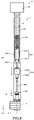
FIG. 2 illustrates thefirst transport device 40 which includes thechuck device 42, amechanical driver 46, and apower transmission mechanism 48, as shown. Themechanical driver 46 includes a rotary air cylinder, for example, and produces a rotary force using pneumatic pressure. Alternatively, themechanical driver 46 may use an electric motor to produce the rotary force. The power generated by themechanical driver 46 is transmitted to thechuck device 42 via thepower transmission mechanism 48, thus actuating thechuck device 42. In particular, thechuck device 42 can grip and release themagazine 4 using the power of themechanical driver 46. Themechanical driver 46 is disposed outside thesample exchange chamber 30. This can prevent the degree of vacuum in thesample exchange chamber 30 from decreasing, i.e., prevent the internal pressure from rising. - The
power transmission mechanism 48 includes afirst shaft 480, aball spline 482, aball screw 484, asecond shaft 486, and aresilient member 488 all of which are incorporated within therod 45. Therod 45 is separated into afirst portion 450 and asecond portion 452. Thefirst shaft 480, the bearing 482b of theball spline 482, and theresilient member 488 are received in thefirst portion 450. Theball screw 484 and thesecond shaft 486 are received in thesecond portion 452. Theball spline 482 has asplined shaft 482a to which thesecond portion 452 is connected. - The
first shaft 480 is coupled to themechanical driver 46 and rotated by the rotary force generated by themechanical driver 46. Theball screw 484 has a threadedshaft 484a to which thefirst shaft 480 is coupled. Thefirst shaft 480 transmits the rotary motion of themechanical driver 46 to theball screw 484. -
FIG. 3 is a schematic cross-sectional view of theball spline 482. Theball spline 482 includes thesplined shaft 482a, thebearing 482b, and aretainer 482c. Theretainer 482c holds a plurality ofballs 482d therein. In theball spline 482, theballs 482d are interposed between grooves respectively formed in thesplined shaft 482a and thebearing 482b. Theball spline 482 can perform rectilinear motion while restricting torque (rotating force) by causing theballs 482d to circulate or roll. - As shown in
FIG. 2 , theball screw 484 transforms the rotary motion of thefirst shaft 480 into a helical motion including a rectilinear motion and the rotary motion and transmits the helical motion to thechuck device 42 via thesecond shaft 486. Theball screw 484 includes the threadedshaft 484a, anut 484b, and balls (not shown). In theball screw 484, the balls roll between the threadedshaft 484a and thenut 484b and so high efficiency can be obtained. - As the
first shaft 480 rotates, the threadedshaft 484a rotates. Thenut 484b is secured to thesecond portion 452 of therod 45. Therefore, as thefirst shaft 480 rotates, the threadedshaft 484a produces helical motion. In this way, theball screw 484 transforms the rotary motion of thefirst shaft 480 into helical motion. The threadedshaft 484a of theball screw 484 is connected to thesecond shaft 486. - As the threaded
shaft 484a effects helical motion, thesecond shaft 486 also performs helical motion. Thesecond shaft 486 transmits the helical motion of the threadedshaft 484a to thechuck device 42. Thesecond shaft 486 has a front end to which abearing 487 is mounted. Since the threadedshaft 484a performs helical motion, thesecond shaft 486 causes rotary motion in addition to rectilinear motion. Because thebearing 487 is mounted to the front end of thesecond shaft 486, only the rectilinear motion of thesecond shaft 486 is transmitted to thechuck device 42; rotary motion is not transmitted. - The
first shaft 480, thesplined shaft 482a, the threadedshaft 484a, and thesecond shaft 486 have their respective central axes located on the same axis A which is parallel to the Z-axis. For example, the axis A coincides with the central axis of therod 45. - The
resilient member 488 is connected to thesplined shaft 482a. Theresilient member 488 may be connected to thesplined shaft 482a via thefirst shaft 480. Theresilient member 488 is located behind thebearing 482b. When a force in the Z direction is applied to thesplined shaft 482a, i.e., a force along the axis A is applied to thesplined shaft 482a, theresilient member 488 elastically deforms. - The
resilient member 488 is a compression coil spring that sustains a compressive load, for example. In the illustrated example, thefirst shaft 480 passes through the compression coil spring. If theresilient member 488 elastically deforms when a force in the Z direction is applied to thesplined shaft 482a, theresilient member 488 is not restricted to a compression coil spring. -
FIGS. 4-7 illustrate thechuck device 42.FIGS. 4 and5 illustrate a state in which themagazine 4 is gripped by thechuck device 42.FIGS. 6 and7 illustrate a state in which themagazine 4 is released by thechuck device 42.FIGS. 5 and7 are views of thechuck device 42 as taken from the Z direction. - As shown in
FIGS. 4-7 , thechuck device 42 includes ashaft 421, ashaft member 422, andballs 424. As shown in these figures, theshaft member 422 has afirst portion 422a and asecond portion 422b of a smaller diameter than thefirst portion 422a. Thesecond portion 422b is located closer to the front end of theshaft member 422 than is thefirst portion 422a, i.e., located more forwardly of the front end of theshaft member 422 in the -Z direction. Threeballs 424 are attached to theshaft member 422. - The
shaft 421 is connected to theshaft member 422. By moving theshaft 421 in the -Z direction, theshaft member 422 moves in the -Z direction. Similarly, by moving theshaft 421 in the +Z direction, theshaft member 422 moves in the +Z direction. - By moving the
shaft 421 in the -Z direction, the threeballs 424 are brought into contact with thefirst portion 422a as shown inFIGS. 4 and5 . By moving theshaft 421 in the +Z direction, the threeballs 424 are brought into contact with thesecond portion 422b as shown inFIGS. 6 and7 . - As mentioned previously, the
second portion 422b is of a smaller diameter than thefirst portion 422a and so when the threeballs 424 are in contact with thesecond portion 422b, theadjacent balls 424 are spaced more closely than when the threeballs 424 are in contact with thefirst portion 422a. Accordingly, when the threeballs 424 are in contact with thesecond portion 422b, a circle interconnecting the threeballs 424 has a diameter smaller than when the threeballs 424 are in contact with thefirst portion 422a. - The
magazine 4 has a top portion provided with a cylindrical mountingportion 8. Theshaft member 422 is inserted from the top opening of the mountingportion 8. The top opening of the mountingportion 8 has a diameter smaller than the inside diameter of the mountingportion 8. Therefore, astep portion 9 is formed inside the mountingportion 8. - Where the
chuck device 42 grips and locks themagazine 4, thechuck device 42 is moved into contact with themagazine 4 and then theshaft member 422 and theballs 424 are pushed into the opening of the mountingportion 8 of themagazine 4. At this time, the threeballs 424 are in a state where they are in contact with thesecond portion 422b as shown inFIGS. 6 and7 . - Then, the
shaft member 422 is moved in the -Z direction. Consequently, as shown inFIGS. 4 and5 , the threeballs 424 come into contact with thefirst portion 422a, increasing the spacing between theadjacent balls 424. As a consequence, theballs 424 are caught on thestep portion 9 and thus themagazine 4 is secured. - Where the
chuck device 42 releases themagazine 4, theshaft member 422 is moved in the +Z direction from the state where themagazine 4 is gripped by thechuck device 42. Consequently, as shown inFIGS. 6 and7 , the threeballs 424 come into contact with thesecond portion 422b, reducing the spacing between theadjacent balls 424. As a result, the threeballs 424 are not caught on thestep portion 9. Hence, themagazine 4 is unlocked and released from thechuck device 42. -
FIGS. 8 and9 illustrate the operation of thepower transmission mechanism 48.FIG. 8 shows a state in which themagazine 4 is gripped by thechuck device 42.FIG. 9 shows a state in which themagazine 4 is released from thechuck device 42. - When the
mechanical driver 46 rotates thefirst shaft 480 counterclockwise as shown inFIG. 8 , the threadedshaft 484a moves helically counterclockwise, thus stretching the threadedshaft 484a in the -Z direction. As a result, thesecond shaft 486 moves in the -Z direction. As shown inFIG. 4 , as thesecond shaft 486 moves in the -Z direction, theshaft member 422 moves in the -Z direction, securing themagazine 4. - When the
mechanical driver 46 rotates thefirst shaft 480 clockwise as shown inFIG. 9 , the threadedshaft 484a moves helically clockwise and becomes elongated in the +Z direction. As a result, thesecond shaft 486 moves in the +Z direction. As thesecond shaft 486 moves in the +Z direction as shown inFIG. 6 , theshaft member 422 moves in the +Z direction, unlocking themagazine 4. Thechuck device 42 releases themagazine 4. -
FIG. 10 illustrates the function of theresilient member 488. Theresilient member 488 moves thechuck device 42 into thesample container 2 with thedrive mechanism 44 and reduces the force produced when thechuck device 42 contacts themagazine 4. For example, if thepower transmission mechanism 48 does not include theresilient member 488, and if thechuck device 42 contacts themagazine 4, thesample container 2 will be pushed in, resulting in a vacuum leak from thevacuum seal 38. - If the
shaft member 422 and theballs 424 are pushed into the opening of the mountingportion 8 of themagazine 4 as shown inFIG. 4 in order to grip themagazine 4 with thechuck device 42, thesecond shaft 486 and the ball screw 484 (threadedshaft 484a and thenut 484b) move in the +Z direction as shown inFIG. 10 . Because thenut 484b is secured to thesecond portion 452 of therod 45, thesecond portion 452 also moves in the +Z direction. - Because the
ball screw 484 moves in the +Z direction, thesplined shaft 482a of theball spline 482 moves in the +Z direction. At this time, theresilient member 488 connected to thesplined shaft 482a elastically deforms. In particular, theresilient member 488 is compressed along the Z-axis and then returns to its original shape. When theshaft member 422 of thechuck device 42 and theballs 424 are pushed into the opening of the mountingportion 8 of themagazine 4, the force applied to themagazine 4 can be reduced by the elastic deformation of theresilient member 488. - The
ball spline 482 can perform rectilinear motion while restricting the torque as described above. Therefore, when a force in the Z direction is applied to thechuck device 42, theball spline 482 can move in the Z direction as mentioned previously. - If a force in the Z direction is applied to the
shaft member 422 of thechuck device 42, thechuck device 42 keeps gripping themagazine 4. Since thefirst transport device 40 includes theball screw 484, if a force in the Z direction is applied to theshaft member 422 of thechuck device 42, the distance D between the front end of the threadedshaft 484a and the front end of theshaft 421 of thechuck device 42 does not vary. Consequently, if a force in the Z direction is applied to theshaft member 422 of thechuck device 42, thechuck device 42 can keep gripping themagazine 4. - In the
chuck device 42, the threadedshaft 484a must be rotated in order to vary the distance D. If a force in the Z direction is applied to theshaft member 422 of thechuck device 42, the threadedshaft 484a does not rotate and so the gripping of themagazine 4 can be maintained. - In the foregoing description, a case has been presented in which a force in the Z direction is applied to the
shaft member 422 while thechuck device 42 is gripping themagazine 4. The same principle also applies to a case where a force in the Z direction is applied to theshaft member 422 while thechuck device 42 is releasing themagazine 4 as shown inFIG. 6 . That is, if a force in the Z direction is applied to theshaft member 422 of thechuck device 42 while thechuck device 42 is releasing themagazine 4, the release of themagazine 4 by thechuck device 42 is maintained. 2.3. Operation of Electron Microscope -
FIGS. 11-14 illustrate the operation of theelectron microscope 100. In theelectron microscope 100, the selectedcartridge 6 received in thesample container 2 can be automatically transported into thesample chamber 10 and attached to the mountingportion 22 of thesample holder 20. - The
cartridge 6 loaded in themagazine 4 is received in thesample container 2, which in turn is mounted to theconnective member 36 as shown inFIG. 11 . At this time, thepartition valve 34 is closed. The user enters an instruction to thecontroller 70 to introduce thecartridge 6. - Upon receiving the instruction for introducing the
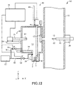
cartridge 6, thecontroller 70 opens thesolenoid valve 64 and evacuates the interior of thesample container 2 to a vacuum. When the interior of thesample container 2 becomes below a given pressure, thecontroller 70 opens thepartition valve 34 as shown inFIG. 12 . - The
controller 70 then moves thechuck device 42 into thesample container 2 and causes thechuck device 42 to grip themagazine 4. In particular, thechuck device 42 is first moved in the -Z direction using thedrive mechanism 44 and brought into contact with themagazine 4 in thesample container 2. Thechuck device 42 is then moved further in the -Z direction with thedrive mechanism 44, and theshaft member 422 and theballs 424 are pushed into the opening of the mountingportion 8 of themagazine 4. Then, themechanical driver 46 is operated to move theshaft member 422 in the -Z direction. Consequently, as shown inFIGS. 4 and5 , the spacing between the threeballs 424 increases, securing themagazine 4. As a result, themagazine 4 can be gripped by thechuck device 42. - When the
chuck device 42 is moved in the -Z direction and theshaft member 422 and theballs 424 are pushed into the opening of the mountingportion 8 of themagazine 4 as described above, a force in the -Z direction is applied to themagazine 4. However, in theelectron microscope 100, as shown inFIG. 10 , theresilient member 488 elastically deforms to thereby reduce the force applied to themagazine 4. Accordingly, if a force in the -Z direction, for example, is applied to themagazine 4, a force in the -Z direction will be applied to thesample container 2. As a result, a gap would normally be created between thesample container 2 and theconnective member 36, causing inflow of air into thesample container 2. - Then, as shown in
FIG. 13 , thechuck device 42 gripping themagazine 4 is transported into thesample exchange chamber 30, then thepartition valve 34 is closed, and thepartition valve 32 is opened under control of thecontroller 70. Thechuck device 52 grips the specifiedcartridge 6 from within themagazine 4 gripped by thechuck device 42, thechuck device 52 having the grippedcartridge 6 is transported into thesample chamber 10, and thecartridge 6 is mounted to the mountingportion 22 also under control of thecontroller 70. - Then, as shown in
FIG. 14 , thecontroller 70 returns thechuck device 52 into thesample exchange chamber 30 and closes thepartition valve 32. Because of the processing steps described so far, thecartridge 6 can be mounted to thesample holder 20. Consequently, the sample held in thecartridge 6 can be observed with theelectron microscope 100. - In the
electron microscope 100, thecartridge 6 can be automatically taken out from the mountingportion 22 of thesample holder 20 and carried into thesample exchange chamber 30. Furthermore, in theelectron microscope 100, themagazine 4 can be automatically returned from thesample exchange chamber 30 to thesample container 2. - As shown in
FIG. 13 , thecontroller 70 opens thepartition valve 32 and moves thechuck device 52 into thesample chamber 10. Then, as shown inFIG. 12 , thecontroller 70 causes thechuck device 52 to grip thecartridge 6 mounted to the mountingportion 22 and carries thecartridge 6 into thesample exchange chamber 30. Then, thecontroller 70 closes thepartition valve 32. Subsequently, thecontroller 70 inserts thecartridge 6 gripped by thechuck device 52 into themagazine 4 gripped by thechuck device 42. - The
controller 70 opens thepartition valve 34, moves thechuck device 42 gripped by themagazine 4 into thesample container 2, and puts themagazine 4 into thesample container 2. Thecontroller 70 operates themechanical driver 46 to move theshaft member 422 in the +Z direction. Consequently, as shown inFIG. 6 , the spacing between the threeballs 424 decreases, thus releasing themagazine 4. - The
controller 70 moves thechuck device 42 in the +Z direction back into thesample exchange chamber 30 as shown inFIG. 11 and closes thepartition valve 32. Because of the processing steps described so far, themagazine 4 can be returned into thesample exchange chamber 30. - In the
electron microscope 100, thefirst transport device 40 includes thechuck device 42 for gripping thecartridge 6 in thesample container 2, thedrive mechanism 44 for moving thechuck device 42 in the Z direction, themechanical driver 46 for actuating thechuck device 42, and thepower transmission mechanism 48 for transmitting power from themechanical driver 46 to thechuck device 42. Thepower transmission mechanism 48 includes thesplined shaft 482a and theresilient member 488 that elastically deforms when a force in the Z direction is applied to thesplined shaft 482a. - In this way, the
electron microscope 100 includes theresilient member 488 which, when a force in the Z direction is applied to thesplined shaft 482a, undergoes elastic deformation. Therefore, when thechuck device 42 grips themagazine 4, the force applied to themagazine 4 can be decreased. For this reason, when thechuck device 42 grips themagazine 4, the force applied to thesample container 2 via themagazine 4 can be reduced. In consequence, inflow of air into thesample container 2 can be prevented; otherwise, the sample may become frosted during cooling of the sample, making it impossible to observe the original shape of the sample. - In the
electron microscope 100, thepower transmission mechanism 48 includes theball spline 482 for restricting rotary motion of themechanical driver 46 and theball screw 484 for transforming the rotary motion transmitted from thefirst shaft 480 into a helical motion including a rectilinear motion and the rotary motion. Thechuck device 42 is operated by the helical motion transmitted from theball screw 484. Therefore, in theelectron microscope 100, if thechuck device 42 is pushed against themagazine 4 and thepower transmission mechanism 48 moves in the Z direction, the distance D between the front end of the threadedshaft 484a and the front end of theshaft 421 of thechuck device 42 does not vary. Accordingly, when thechuck device 42 is gripping themagazine 4, if an impact is applied to thechuck device 42, the gripping of themagazine 4 can be maintained. Similarly, when thechuck device 42 unlocks and releases themagazine 4, if an impact is applied to thechuck device 42, the releasing of themagazine 4 can be maintained. - In the
electron microscope 100, theresilient member 488 is connected to thesplined shaft 482a of theball spline 482 and elastically deforms when a force in the Z direction is applied to thesplined shaft 482a. Theball spline 482 can perform a rectilinear motion while restricting the torque. Therefore, when a force in the Z direction is applied to theshaft member 422 of thechuck device 42 as described above, thesplined shaft 482a can be moved in the Z direction. - In the foregoing embodiment, the charged particle beam system associated with the present invention has been described in which an electron microscope for observing or analyzing a sample using an electron beam is taken as an example. The charged particle beam system associated with the present invention may also be an instrument for making an observation or analysis of a sample using a charged particle beam other than an electron beam such as an ion beam. For example, the charged particle beam system associated with the present invention may be a scanning transmission electron microscope, a scanning electron microscope, an Auger electron spectrometer, a focused ion beam system, or the like.
- It is to be understood that the present invention is not restricted to the above embodiment and modifications thereof and that the invention can be practiced in further modified forms. For example, the present invention embraces configurations substantially identical (e.g., in function or method) to the configurations described in the above embodiment. Furthermore, the present invention embraces configurations similar to the configurations described in the above embodiment except that nonessential portions have been replaced. Further, the present invention embraces configurations similar to the configurations described in the above embodiment except that a well-known technique is added.
Claims (5)
- A charged particle beam system comprising:a sample chamber;a sample exchange chamber connected to the sample chamber;a sample container capable of being removably attached in the sample exchange chamber; anda transport device for transporting a sample between the sample container and the sample exchange chamber;wherein the transport device includes a chuck device for gripping the sample, a drive mechanism for moving the chuck device in a given direction, a mechanical driver for actuating the chuck device, and a power transmission mechanism for transmitting power of the mechanical driver to the chuck device; andwherein the power transmission mechanism includes a shaft and a resilient member that elastically deforms when a force in the given direction is applied to the shaft.
- A charged particle beam system as set forth in claim 1, wherein said power transmission mechanism includes a ball spline for restricting rotary motion of said mechanical driver and a ball screw for transforming the rotary motion transmitted from said shaft into a helical motion including a rectilinear motion and the rotary motion, and wherein said chuck device is operated by the helical motion transmitted from the ball screw.
- A charged particle beam system as set forth in claim 2, whereinsaid ball screw includes a threaded shaft,said shaft transmits the rotary motion to the threaded shaft, andthe threaded shaft is caused to perform helical motion by the rotary motion of the shaft.
- A charged particle beam system as set forth in any one of claims 1 to 3, wherein said mechanical driver is disposed outside said sample exchange chamber.
- A charged particle beam system as set forth in any one of claims 1 to 4, further comprising a vacuum seal mounted between said sample exchange chamber and said sample container.
Applications Claiming Priority (1)
| Application Number | Priority Date | Filing Date | Title |
|---|---|---|---|
| JP2021002167A JP7267318B2 (en) | 2021-01-08 | 2021-01-08 | Charged particle beam device |
Publications (1)
| Publication Number | Publication Date |
|---|---|
| EP4027368A1 true EP4027368A1 (en) | 2022-07-13 |
Family
ID=79024936
Family Applications (1)
| Application Number | Title | Priority Date | Filing Date |
|---|---|---|---|
| EP21217690.3A Pending EP4027368A1 (en) | 2021-01-08 | 2021-12-24 | Charged particle beam system |
Country Status (3)
| Country | Link |
|---|---|
| US (1) | US11631569B2 (en) |
| EP (1) | EP4027368A1 (en) |
| JP (1) | JP7267318B2 (en) |
Families Citing this family (1)
| Publication number | Priority date | Publication date | Assignee | Title |
|---|---|---|---|---|
| CN119002186B (en) * | 2024-07-26 | 2025-09-30 | 中国电子科技集团公司第四十八研究所 | A substrate disc locking device for electron beam exposure machine and control method thereof |
Citations (3)
| Publication number | Priority date | Publication date | Assignee | Title |
|---|---|---|---|---|
| JP2015088237A (en) | 2013-10-28 | 2015-05-07 | 日本電子株式会社 | Charged particle beam device and sample container |
| EP3038131A1 (en) * | 2014-12-22 | 2016-06-29 | FEI Company | Improved specimen holder for a charged particle microscope |
| US20170133197A1 (en) * | 2015-08-12 | 2017-05-11 | Jeol Ltd. | Charged Particle Beam System |
Family Cites Families (5)
| Publication number | Priority date | Publication date | Assignee | Title |
|---|---|---|---|---|
| JP3325389B2 (en) | 1994-06-29 | 2002-09-17 | 日本電子株式会社 | Electron microscope sample equipment |
| JPH11185686A (en) * | 1997-12-25 | 1999-07-09 | Jeol Ltd | Sample holder, sample holder mounting holder and sample holder |
| JP4394778B2 (en) * | 1999-09-22 | 2010-01-06 | 東京エレクトロン株式会社 | Plasma processing apparatus and plasma processing method |
| JP3778008B2 (en) | 2001-06-12 | 2006-05-24 | 株式会社日立製作所 | Sample preparation equipment |
| US7381971B2 (en) * | 2004-07-28 | 2008-06-03 | Omniprobe, Inc. | Method and apparatus for in-situ probe tip replacement inside a charged particle beam microscope |
-
2021
- 2021-01-08 JP JP2021002167A patent/JP7267318B2/en active Active
- 2021-12-24 EP EP21217690.3A patent/EP4027368A1/en active Pending
-
2022
- 2022-01-07 US US17/570,749 patent/US11631569B2/en active Active
Patent Citations (3)
| Publication number | Priority date | Publication date | Assignee | Title |
|---|---|---|---|---|
| JP2015088237A (en) | 2013-10-28 | 2015-05-07 | 日本電子株式会社 | Charged particle beam device and sample container |
| EP3038131A1 (en) * | 2014-12-22 | 2016-06-29 | FEI Company | Improved specimen holder for a charged particle microscope |
| US20170133197A1 (en) * | 2015-08-12 | 2017-05-11 | Jeol Ltd. | Charged Particle Beam System |
Also Published As
| Publication number | Publication date |
|---|---|
| JP2022107301A (en) | 2022-07-21 |
| US20220223371A1 (en) | 2022-07-14 |
| US11631569B2 (en) | 2023-04-18 |
| JP7267318B2 (en) | 2023-05-01 |
Similar Documents
| Publication | Publication Date | Title |
|---|---|---|
| JP5745757B2 (en) | Charged particle optics with double mounting optics | |
| JP7449872B2 (en) | Sample handling systems, mass spectrometers and related methods | |
| US9443707B2 (en) | Method and apparatus for transporting samples in a mass spectrometer | |
| US12362133B2 (en) | Transport device and charged particle beam system | |
| US9881768B2 (en) | Charged Particle Beam System With Receptacle Chamber For Cleaning Sample and Sample Stage | |
| US11881377B2 (en) | Automated multi-grid handling apparatus | |
| US11631569B2 (en) | Charged particle beam system | |
| CN103155089A (en) | Sample device for charged particle beam | |
| AU2026200390A1 (en) | Load lock chamber assemblies for sample analysis systems and related mass spectrometer systems and methods | |
| US12112917B2 (en) | Sample holder and charged particle beam system | |
| CN105836403A (en) | Sample carrying device and vacuum apparatus | |
| US9362095B1 (en) | Method and apparatus for transporting samples in a mass spectrometer | |
| US11640895B2 (en) | Sample holder and charged particle beam system | |
| US9318301B2 (en) | Sample introduction device and charged particle beam instrument | |
| CN111122632A (en) | Method for preparing biological samples for study in charged particle devices | |
| JP2002365182A (en) | Sample preparation equipment | |
| JP6130185B2 (en) | Sample introduction apparatus and charged particle beam apparatus | |
| JP2986129B2 (en) | Ion beam analyzer | |
| KR100580963B1 (en) | Nano processing system | |
| WO2025253620A1 (en) | Charged particle beam device and sample holder | |
| CA3091004C (en) | Sample handling systems, mass spectrometers and related methods | |
| JP4135013B2 (en) | Sample preparation equipment | |
| CN121601532A (en) | Teaching charged particle microscope robot grippers via beam splitting | |
| KR20260027070A (en) | Vacuum simulation for charged-particle microscopy grid receptacles | |
| JP2000338062A (en) | Surface analyzer |
Legal Events
| Date | Code | Title | Description |
|---|---|---|---|
| PUAI | Public reference made under article 153(3) epc to a published international application that has entered the european phase |
Free format text: ORIGINAL CODE: 0009012 |
|
| STAA | Information on the status of an ep patent application or granted ep patent |
Free format text: STATUS: THE APPLICATION HAS BEEN PUBLISHED |
|
| AK | Designated contracting states |
Kind code of ref document: A1 Designated state(s): AL AT BE BG CH CY CZ DE DK EE ES FI FR GB GR HR HU IE IS IT LI LT LU LV MC MK MT NL NO PL PT RO RS SE SI SK SM TR |
|
| STAA | Information on the status of an ep patent application or granted ep patent |
Free format text: STATUS: REQUEST FOR EXAMINATION WAS MADE |
|
| 17P | Request for examination filed |
Effective date: 20221130 |
|
| RBV | Designated contracting states (corrected) |
Designated state(s): AL AT BE BG CH CY CZ DE DK EE ES FI FR GB GR HR HU IE IS IT LI LT LU LV MC MK MT NL NO PL PT RO RS SE SI SK SM TR |
|
| STAA | Information on the status of an ep patent application or granted ep patent |
Free format text: STATUS: EXAMINATION IS IN PROGRESS |
|
| 17Q | First examination report despatched |
Effective date: 20240808 |