EP4027089A1 - Refrigerator - Google Patents
Refrigerator Download PDFInfo
- Publication number
- EP4027089A1 EP4027089A1 EP21215279.7A EP21215279A EP4027089A1 EP 4027089 A1 EP4027089 A1 EP 4027089A1 EP 21215279 A EP21215279 A EP 21215279A EP 4027089 A1 EP4027089 A1 EP 4027089A1
- Authority
- EP
- European Patent Office
- Prior art keywords
- valve body
- pipe part
- water
- refrigerator
- valve
- Prior art date
- Legal status (The legal status is an assumption and is not a legal conclusion. Google has not performed a legal analysis and makes no representation as to the accuracy of the status listed.)
- Pending
Links
- XLYOFNOQVPJJNP-UHFFFAOYSA-N water Substances O XLYOFNOQVPJJNP-UHFFFAOYSA-N 0.000 claims abstract description 192
- 230000002265 prevention Effects 0.000 claims abstract description 33
- 238000007599 discharging Methods 0.000 claims abstract description 6
- 238000007789 sealing Methods 0.000 claims description 37
- 230000008878 coupling Effects 0.000 claims description 35
- 238000010168 coupling process Methods 0.000 claims description 35
- 238000005859 coupling reaction Methods 0.000 claims description 35
- 230000006835 compression Effects 0.000 claims description 13
- 238000007906 compression Methods 0.000 claims description 13
- 238000010438 heat treatment Methods 0.000 claims description 10
- 239000000463 material Substances 0.000 claims description 6
- 230000000903 blocking effect Effects 0.000 claims description 3
- 238000011144 upstream manufacturing Methods 0.000 claims description 2
- 239000011810 insulating material Substances 0.000 claims 1
- 230000005494 condensation Effects 0.000 description 14
- 238000009833 condensation Methods 0.000 description 14
- 238000000034 method Methods 0.000 description 5
- 230000015572 biosynthetic process Effects 0.000 description 3
- 238000003825 pressing Methods 0.000 description 3
- 230000000694 effects Effects 0.000 description 2
- 238000007710 freezing Methods 0.000 description 2
- 230000008014 freezing Effects 0.000 description 2
- 229920001296 polysiloxane Polymers 0.000 description 2
- 238000001816 cooling Methods 0.000 description 1
- 230000007423 decrease Effects 0.000 description 1
- 238000012217 deletion Methods 0.000 description 1
- 230000037430 deletion Effects 0.000 description 1
- 235000006694 eating habits Nutrition 0.000 description 1
- 230000013011 mating Effects 0.000 description 1
- 239000003507 refrigerant Substances 0.000 description 1
- 238000005057 refrigeration Methods 0.000 description 1
- 239000012780 transparent material Substances 0.000 description 1
Images


Classifications
-
- F—MECHANICAL ENGINEERING; LIGHTING; HEATING; WEAPONS; BLASTING
- F25—REFRIGERATION OR COOLING; COMBINED HEATING AND REFRIGERATION SYSTEMS; HEAT PUMP SYSTEMS; MANUFACTURE OR STORAGE OF ICE; LIQUEFACTION SOLIDIFICATION OF GASES
- F25D—REFRIGERATORS; COLD ROOMS; ICE-BOXES; COOLING OR FREEZING APPARATUS NOT OTHERWISE PROVIDED FOR
- F25D23/00—General constructional features
- F25D23/12—Arrangements of compartments additional to cooling compartments; Combinations of refrigerators with other equipment, e.g. stove
- F25D23/126—Water cooler
-
- F—MECHANICAL ENGINEERING; LIGHTING; HEATING; WEAPONS; BLASTING
- F25—REFRIGERATION OR COOLING; COMBINED HEATING AND REFRIGERATION SYSTEMS; HEAT PUMP SYSTEMS; MANUFACTURE OR STORAGE OF ICE; LIQUEFACTION SOLIDIFICATION OF GASES
- F25D—REFRIGERATORS; COLD ROOMS; ICE-BOXES; COOLING OR FREEZING APPARATUS NOT OTHERWISE PROVIDED FOR
- F25D23/00—General constructional features
- F25D23/02—Doors; Covers
- F25D23/028—Details
-
- B—PERFORMING OPERATIONS; TRANSPORTING
- B67—OPENING, CLOSING OR CLEANING BOTTLES, JARS OR SIMILAR CONTAINERS; LIQUID HANDLING
- B67D—DISPENSING, DELIVERING OR TRANSFERRING LIQUIDS, NOT OTHERWISE PROVIDED FOR
- B67D3/00—Apparatus or devices for controlling flow of liquids under gravity from storage containers for dispensing purposes
- B67D3/0025—Apparatus or devices for controlling flow of liquids under gravity from storage containers for dispensing purposes provided with dispensing valves actuated by the receptacle to be filled
-
- B—PERFORMING OPERATIONS; TRANSPORTING
- B67—OPENING, CLOSING OR CLEANING BOTTLES, JARS OR SIMILAR CONTAINERS; LIQUID HANDLING
- B67D—DISPENSING, DELIVERING OR TRANSFERRING LIQUIDS, NOT OTHERWISE PROVIDED FOR
- B67D3/00—Apparatus or devices for controlling flow of liquids under gravity from storage containers for dispensing purposes
- B67D3/0058—Details
- B67D3/008—Supports
-
- B—PERFORMING OPERATIONS; TRANSPORTING
- B67—OPENING, CLOSING OR CLEANING BOTTLES, JARS OR SIMILAR CONTAINERS; LIQUID HANDLING
- B67D—DISPENSING, DELIVERING OR TRANSFERRING LIQUIDS, NOT OTHERWISE PROVIDED FOR
- B67D3/00—Apparatus or devices for controlling flow of liquids under gravity from storage containers for dispensing purposes
- B67D3/04—Liquid-dispensing taps or cocks adapted to seal and open tapping holes of casks, e.g. for beer
- B67D3/043—Liquid-dispensing taps or cocks adapted to seal and open tapping holes of casks, e.g. for beer with a closing element having a linear movement, in a direction perpendicular to the seat
-
- F—MECHANICAL ENGINEERING; LIGHTING; HEATING; WEAPONS; BLASTING
- F25—REFRIGERATION OR COOLING; COMBINED HEATING AND REFRIGERATION SYSTEMS; HEAT PUMP SYSTEMS; MANUFACTURE OR STORAGE OF ICE; LIQUEFACTION SOLIDIFICATION OF GASES
- F25D—REFRIGERATORS; COLD ROOMS; ICE-BOXES; COOLING OR FREEZING APPARATUS NOT OTHERWISE PROVIDED FOR
- F25D21/00—Defrosting; Preventing frosting; Removing condensed or defrost water
- F25D21/04—Preventing the formation of frost or condensate
-
- F—MECHANICAL ENGINEERING; LIGHTING; HEATING; WEAPONS; BLASTING
- F25—REFRIGERATION OR COOLING; COMBINED HEATING AND REFRIGERATION SYSTEMS; HEAT PUMP SYSTEMS; MANUFACTURE OR STORAGE OF ICE; LIQUEFACTION SOLIDIFICATION OF GASES
- F25D—REFRIGERATORS; COLD ROOMS; ICE-BOXES; COOLING OR FREEZING APPARATUS NOT OTHERWISE PROVIDED FOR
- F25D23/00—General constructional features
- F25D23/02—Doors; Covers
- F25D23/04—Doors; Covers with special compartments, e.g. butter conditioners
-
- F—MECHANICAL ENGINEERING; LIGHTING; HEATING; WEAPONS; BLASTING
- F25—REFRIGERATION OR COOLING; COMBINED HEATING AND REFRIGERATION SYSTEMS; HEAT PUMP SYSTEMS; MANUFACTURE OR STORAGE OF ICE; LIQUEFACTION SOLIDIFICATION OF GASES
- F25D—REFRIGERATORS; COLD ROOMS; ICE-BOXES; COOLING OR FREEZING APPARATUS NOT OTHERWISE PROVIDED FOR
- F25D2323/00—General constructional features not provided for in other groups of this subclass
- F25D2323/02—Details of doors or covers not otherwise covered
-
- F—MECHANICAL ENGINEERING; LIGHTING; HEATING; WEAPONS; BLASTING
- F25—REFRIGERATION OR COOLING; COMBINED HEATING AND REFRIGERATION SYSTEMS; HEAT PUMP SYSTEMS; MANUFACTURE OR STORAGE OF ICE; LIQUEFACTION SOLIDIFICATION OF GASES
- F25D—REFRIGERATORS; COLD ROOMS; ICE-BOXES; COOLING OR FREEZING APPARATUS NOT OTHERWISE PROVIDED FOR
- F25D2323/00—General constructional features not provided for in other groups of this subclass
- F25D2323/122—General constructional features not provided for in other groups of this subclass the refrigerator is characterised by a water tank for the water/ice dispenser
-
- F—MECHANICAL ENGINEERING; LIGHTING; HEATING; WEAPONS; BLASTING
- F25—REFRIGERATION OR COOLING; COMBINED HEATING AND REFRIGERATION SYSTEMS; HEAT PUMP SYSTEMS; MANUFACTURE OR STORAGE OF ICE; LIQUEFACTION SOLIDIFICATION OF GASES
- F25D—REFRIGERATORS; COLD ROOMS; ICE-BOXES; COOLING OR FREEZING APPARATUS NOT OTHERWISE PROVIDED FOR
- F25D2331/00—Details or arrangements of other cooling or freezing apparatus not provided for in other groups of this subclass
- F25D2331/80—Type of cooled receptacles
- F25D2331/806—Dispensers
Definitions
- the present disclosure relates to a refrigerator.
- a refrigerator is a home appliance that can store food at a low temperature in an internal storage space that is shielded by a door.
- the refrigerator is configured to store the stored food in an optimal state by cooling the inside of the storage space using cold air generated through heat exchange with a refrigerant circulating in the refrigeration cycle.
- refrigerators are gradually becoming larger and more multifunctional in accordance with changes in dietary habits and the trend of luxury products, and refrigerators having various structures and convenience devices in consideration of user convenience are being released.
- a refrigerator equipped with a dispenser for taking out water from a refrigerator door or an ice maker for making ice in a freezing chamber or a freezing chamber door is being developed.
- a water tank in which water supplied to the dispenser is stored may be detachably provided on the rear surface of the refrigerating chamber door.
- a water dispenser for the refrigerator capable of external water supply is disclosed so that water can be replenished to a water tank mounted inside from the outside of the door without opening the refrigerator door by building a simple structure inside the wall surface of the refrigerator door.
- Such a conventional refrigerator has a problem that dew condensation occurs around a valve body formed to take out water by being connected to a water tank under the influence of external temperature and humidity.
- An object of the present disclosure is to provide a refrigerator including a dispenser capable of preventing dew condensation from forming around a valve body connected to a water tank.
- An object of the present disclosure is to provide a refrigerator capable of preventing the residual water from falling by minimizing the amount of water remaining in a valve body.
- a refrigerator comprising: a cabinet forming a storage space; a door configured to open and close the storage space; and a dispenser provided at the door, e.g. a front surface of the door, for dispensing water out of the refrigerator.
- the dispenser comprises a water take-out valve.
- the refrigerator further includes a water tank for storing water and provided in the storage space above the dispenser and including a drain port for discharging the water stored therein.
- the water take-out valve comprising: a pipe part communicating with the drain port of the water tank to receive the water discharged from the drain port and including an inner surface defining a flow passage for the water so received; and a valve body disposed inside the flow passage of the pipe part and slidingly movable back and forth inside the flow passage of the pipe part along a longitudinal direction of the pipe part to open and close an opening and closing surface of the pipe part for allowing and blocking dispensing of water from the dispenser.
- the valve body includes an extension part extending from a surface of the valve body toward the inner surface of the pipe part.
- the water take-out valve comprises a leak prevention ring provided around the extension part and configured to contact the inner surface of the pipe part to seal a gap between the inner surface of the pipe part and the valve body, in a state when the opening and closing surface is closed by the valve body.
- a refrigerator includes a cabinet configured to form a storage space, a door configured to open and close the storage space, a dispenser configured to be formed on a front surface of the door, a water tank configured to be provided detachably from the door above the dispenser and including a drain port for discharging stored water, a pipe part configured to communicate with the water tank to form a passage for discharging water, and a water intake valve (water take-out valve) including a valve body that slides along the longitudinal direction of the pipe part and opens and closes an opening and closing surface or region of the pipe part, wherein the valve body includes an extension part configured to extend from one surface of the valve body toward an inner surface of the passage, and a leak prevention ring configured to be provided around the extension part to seal between the pipe part and the valve body in a state where the opening and closing surface is closed by the valve body.
- a water intake valve water take-out valve
- the refrigerator according to the aforementioned first aspect or the aforementioned second aspect may include one or more of the following.
- the pipe part may include an outer wall configured to form a part of an outer surface of the water intake valve.
- the pipe part may include an inner wall provided to be spaced apart from the outer wall and having a smaller diameter than the outer wall.
- the leak prevention ring may be formed to be in contact with the inner wall when the opening and closing surface is closed by the valve body.
- the leak prevention ring may be provided at an upper end of the valve body to block water from the drain port from flowing into a space between the pipe part and the valve body.
- the valve body may include a first valve body inserted into the inner wall and slidingly moved in the longitudinal direction of the pipe part.
- the valve body may include a second valve body formed along the circumferential surface of the first valve body and formed to be in contact with a portion of the inner wall.
- the extension part may extend from one surface of the second valve body in a direction of the pipe part.
- a groove recessed in the central direction of the valve body may be formed on the outer surface of the extension part.
- the leak prevention ring may be mounted in the groove.
- the leak prevention ring may be provided to be spaced apart from the inside of the drain port at a predetermined interval.
- the valve body may include a coupling ring configured to seal a gap between the first valve body and the second valve body.
- the extension part may be formed to have a cross-sectional area that increases from the center of the valve body toward the inner wall.
- the extension part may include an inclined part configured to be in contact with the coupling ring.
- the upper end of the extension part may be positioned on the same extension line as the coupling ring.
- a fastening part into which the drain port is inserted may be provided in the upper end of the inside of the drain port.
- a sealing part spaced apart between the fastening part and the drain port may be provided in the fastening part.
- the sealing part may extend along the longitudinal direction of the fastening part.
- the sealing part may be in surface contact with the drain port.
- the sealing part may be made of elastically deformable material.
- the sealing part may be made of elastically deformable rubber or silicone material.
- a compression ring sealing the end portion of the drain port may be provided in one end of the fastening part.
- the sealing part may be provided to be in contact with a portion of the compression ring.
- the pipe part and the valve body may be provided in the refrigerator door.
- a take-out lever may be installed on the door.
- the force for pressing one side of the take-out lever may be transmitted to the valve body so that the valve body opens the opening and closing surface of a pipe part.
- the door may include a front plate configured to form an outer appearance of a front surface.
- the door may include a door liner configured to form a rear surface.
- the door may include a dispenser fixing part formed to support a portion of the dispenser on the rear surface of the front plate.
- a connector into which the water intake valve is inserted may be provided above the dispenser fixing part.
- a heating wire may be attached to the outer circumferential surface of the connector.
- phrases such as 'in', 'inward', 'out', 'outward', 'front', 'back', 'backward', and like phrases are to construed with respect to a front-rear direction of the refrigerator unless otherwise specified, for example from a front opening (at which the door is provided) of the cabinet towards the storage space or rear wall of the cabinet (or rear surface of the storage space) unless otherwise specified.
- phrases such as 'up', 'upward', 'down', 'downward' are to be construed with respect to a vertical direction of the refrigerator unless otherwise specified, for example when the refrigerator is positioned/orientated to be in position for use.
- the water take-out valve may have inlet end i.e. end at which water from the water tank is received, and an outlet end i.e. end at which water so received is dispensed out of the water take-out valve.
- the inlet end and the outlet end of the water take-out valve may be spaced apart along a longitudinal direction or axis of the water take-out valve.
- phrases such as 'in', 'inward', 'out', 'outward', 'up', 'upward' 'down' 'downward' 'front', 'forward' 'back', 'backward', and like phrases with respect to the water take-out valve or components or parts of the water take-out valve may be understood with respect to the longitudinal direction or axis of the water take-out valve, wherein 'in', 'inward', 'back', 'backward', 'up' 'upward' and like phrase indicate or direct towards the inlet end of the water take-out valve - unless otherwise indicated, and the phrases such as 'out', 'outward', 'down' 'downward' 'front', 'forward', and like phrase indicate or direct towards the outlet end of the water take-out valve - unless otherwise indicated.
- the water take-out valve may have a longitudinally extending shape, extending along a longitudinal axis, and the inlet end and the outlet end may be spaced apart along the longitudinal axis.
- the refrigerator according to the present disclosure can expect the following effects.
- the present disclosure includes an extension part extending in the direction of the inner wall of the pipe part from the upper end of the valve body, and a leak prevention ring mounted around the extension part. Accordingly, in a state where the opening and closing surface of the pipe part is closed by the valve body, it is possible to maintain a sealed state between the pipe part and the valve body. Accordingly, water flowing through the drain port of the water tank may be blocked by the leak prevention ring, thereby preventing the water from flowing into the pipe part.
- the present disclosure is characterized in that a sealing part is provided inside the pipe part into which the drain port is inserted.
- the sealing part may separate the drain port inserted into the pipe part by a predetermined distance from the pipe part. Accordingly, it is possible to prevent direct conduction of heat from the drain port, whose temperature is lowered by the water in the water tank, to the pipe part. Thereby, it is possible to prevent dew condensation from occurring around the pipe part.
- a heating wire may be provided on an outer circumferential surface of a connector which is formed on the door and into which the water take-out valve is inserted. Accordingly, it is possible to prevent a temperature difference between the inside and outer surfaces of the door from occurring due to the water flowing through the water take-out valve. Accordingly, it is possible to prevent dew condensation from occurring around the connector and the door.
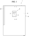
- Fig. 1 is a front view illustrating a refrigerator according to an embodiment of the present disclosure.
- the refrigerator 1 may include a cabinet 10 forming a storage space, and a door 20 disposed in front of the cabinet to open and close the storage space.
- the door 20 may be disposed by being hinged with the cabinet 10 and may open and close the storage space by rotation.
- a handle 201 recessed inwardly on the front surface of the door 20 to allow a user to open and close the door 20 may be provided.
- a dispenser 30 may be provided on the front surface of the door 20.
- the dispenser 30 allows a user to take out water by operating the dispenser from the outside, has a recessed part recessed from the front surface toward the rear of the door 20, and can be operated by a take-out lever 32 from the outside so that the water is taken out or dispensed.
- the refrigerator is described as an example of a refrigerator having a single door 20, but as an example, the cabinet may form a storage space that is partitioned e.g. up and down and/or left-right, and the refrigerator may have corresponding doors e.g. an upper door disposed in upper part of the cabinet and a lower door disposed is lower part the cabinet, respectively, and the dispenser 30 is not limited to the position and shape of the door, and it should be noted in advance that it can be applied to various types of refrigerator doors.
- Fig. 2 is a cross-sectional view taken along line II-II' of Fig. 1 and Fig. 3 is a side sectional view illustrating the structure of a water tank according to an embodiment of the present disclosure.
- the dispenser 30 is provided on the front surface of the door 20, and a water tank 40 is mounted behind the door 20, e.g. on the rear surface of the door 20.
- the door 20 may include a front plate that forms an outer appearance of the front surface of the door, and a door liner that is coupled to the front plate to form a rear surface of the door.
- a water tank 40 may be detachably mounted behind and/or on the rear surface of the door 20.
- the water tank 40 is for storing water supplied to the dispenser 30 and may be provided behind or at or on the rear surface of the door 20. Accordingly, the water tank 40 may be located inside the refrigerating chamber and naturally cooled by the cold air inside the refrigerating chamber to provide cooled water to the dispenser 30.
- the water tank 40 may be located above the dispenser 30, so that when the dispenser 30 is operated, the water inside the water tank 40 can be supplied to the dispenser 30 by its own weight.
- the water tank 40 may include a tank body 41 in which water is stored, and a tank cover 42 that shields or covers or caps the opened upper surface of the tank body 41.
- a tank body 41 in which water is stored
- a tank cover 42 that shields or covers or caps the opened upper surface of the tank body 41.
- at least a part of the tank body 41 may be made of a transparent material, and the user may easily check the amount of water stored in the water tank 40.
- a drain port 43 may be provided at the lower end of the water tank 40.
- the drain port 43 may extend downward to allow the water of the water tank 40 to be taken out or dispensed from the dispenser 30.
- the drain port 43 may extend toward the water take-out space while facing the front of the door.
- the drain port 43 may extend from the rear side/surface of the door downward toward the front side/surface of the door 20.
- the outer circumferential surface of the drain port 43 includes a valve coupling part 431 for example formed of or as a screw thread.
- the valve coupling part 431 may be fastened to a corresponding coupling or fastening part 511 provided at the upper end of a pipe part 51 (or piping part 51) of a water take-out valve 50, e.g. a screw thread of the valve coupling part 431 may be mated with the coupling part 511 provided on or at the upper end of the pipe part 51 of the water take-out valve 50.
- drain port 43 or the outer circumferential surface of the drain port 43 may be formed in various shapes in which the drain port 43 can be inserted and fixed inside the pipe part 51 in addition to the screw thread, and is not limited thereto.
- the valve coupling part 431 is in surface contact with a sealing part 512 to be described later.
- the sealing part 512 may be provided between the valve coupling part 431 and the fastening part 511.
- the sealing part 512 prevents the temperature of the drain port 43 cooled by the water of the water tank 40 from being conducted to the fastening part 511, thereby being capable of preventing the temperature of the valve body 55 from being lowered. Accordingly, it is possible to prevent dew condensation from forming around the valve body 55.
- the sealing part 512 may be a thermally insulating part or insert.
- Fig. 4 is a side sectional view illustrating a water take-out valve according to an embodiment of the present disclosure
- Fig. 5 is a side sectional view illustrating a state where the water tank and the water take-out valve are fastened or coupled
- Fig. 6 is a cross-sectional view illustrating a state where the water take-out valve is opened, in contrast to Fig. 5 where the water take-out valve is closed.
- the water take-out valve 50 of the present disclosure includes a valve body 55 provided inside the piping part 51 serving as a passage through which water of a water tank flows.
- a fastening part 511 into which the drain port 43 of the water tank 40 is inserted is formed inside the pipe part 51.
- a sealing part 512 that is in surface contact with the fastening part 511 is provided inside the pipe part 51.
- the sealing part 512 may be provided between the valve coupling part 431 and the fastening part 511.
- the valve coupling part 431 and the coupling part 511 may be spaced apart from each other by the sealing part 512.
- the valve coupling part 431 and the coupling part 511 may be spaced apart from each other by the sealing part 512 such that the valve coupling part 431 and the coupling part 511 are thermally disconnected from each other.
- the valve coupling part 431 and the coupling part 511 may not be in direct physical contact with each other.
- the water tank 40 and the water take-out valve 50 may not be in direct physical contact with each other.
- the sealing part 512 may be formed of an elastically deformable material e.g. rubber or silicone material and may be configured to be fixed between the fastening part 511 and the valve coupling part 431 e.g. by an interference fit method, adhesion, or mating.
- an elastically deformable material e.g. rubber or silicone material
- One surface of the sealing part 512 in contact with the valve coupling part 431 may be formed in a shape to mate with the valve coupling part 431.
- the other surface of the sealing part 512 in contact with the fastening part 511 may be formed in a shape to mate with the fastening part 511.
- the sealing part 512 may extend from an end portion to the other end portion of the fastening part 511, for example along an entire length or continuously along an entire length.
- the sealing part 512 may extend from an end portion to the other end portion of the valve coupling part 431, for example along an entire length or continuously along an entire length.
- the sealing part 512 may extend to contact a portion of a compression ring 513.
- the sealing part 512 may block direct conduction of heat from the drain port 43 cooled by the temperature of the water stored in the water tank 40 to the valve body 55. In other words, it is possible to prevent the heat of the water tank 40 cooled by water from being directly transmitted to the valve body 55, that is, the pipe part 51 by the sealing part 512. Accordingly, it is possible to prevent the temperature of the valve body 55 from being lowered by the temperature of the water, and thus it is possible to prevent dew condensation around the pipe part.
- a compression ring 513 for sealing between the end portion of the drain port 43 and the end portion of the pipe part 51 may be provided.
- the compression ring 513 has a rectangular cross section. Since the compression ring 513 has a rectangular cross section, it can be sealed even if there is a slight difference in size and shape between the end portion of the drain port 43 of the water tank 40 and the end portion of the pipe part 51.
- the water take-out valve 50 is provided with an outer wall 52 extending from the pipe part 51 and forming a portion of the outer surface of the water take-out valve 50 and an inner wall 53 spaced apart from the outer wall 52 and having a smaller diameter than the outer wall 52.
- the hollow portion 521 defined by the interval between the inner wall 53 and the outer wall 52 may be provided below the compression ring 513.
- An elastic body 522 such as a compression coil spring is installed in the hollow portion 521, wherein the elastic body 522 elastically supports the valve body 55 with respect to the pipe part 51 in a direction in which the valve body 55 is pushed.
- the take-out lever 32 When the take-out lever 32 is pressed by the user, the force that the user presses on the take-out lever counteracts or overcomes the elastic force of the elastic body 522 and the valve body 55 is moved or inserted toward the pipe part 51. Then, when the user releases the force pressing the take-out lever by completing water intake or the like, the valve body 55 slides toward the end portion of the pipe part by action of the elastic body 522.
- the inner wall 53 may be formed to extend further inward than the position in which the compression ring 513 is provided in the inner space of the water take-out valve 50.
- the inner wall 53 may be partitioned into a first inner wall 531 positioned above a reduced diameter part 533 and a second inner wall 532 positioned lower than the first inner wall 531.
- An inner diameter of the first inner wall 531 may be larger than an inner diameter of the second inner wall 532.
- the reduced diameter part 533 may be between the first inner wall 531 and the second inner wall 532.
- the reduced diameter part 533 may have an inclination such that the diameter gradually decreases as it moves downward along the length direction of the pipe part 51, i.e. from the first inner wall 531 toward the second inner wall 532.
- the reduced diameter part 533 may have an inclined surface 534 to be in close contact with an opening and closing ring 35 of the valve body, which will be described later.
- An outer insert ring 506 may be selectively fitted to the inner wall part of the reduced diameter part 533.
- an outer insert part 503 of the valve body may be inserted into the space between the second inner wall 532 and the outer wall 52.
- valve body 55 according to an embodiment of the present disclosure is fitted to the pipe part 51 and slides along the longitudinal direction of the pipe part 51 to open and close an opening and closing surface or region 54.
- the valve body 55 includes a second valve body 57 inserted into the inner wall 53 e.g. inserted into a first inner wall 531from an end portion of the pipe part 51, and a first valve body 56 inserted into the second valve body 57.
- a coupling ring 561 for sealing a gap generated between the first and second valve bodies 57 may be provided.
- the second valve body 57 has two or more blade shapes projecting radially, and the end portion of the blade cooperates with the inner wall surface of the first inner wall 531 to guide the sliding movement of the valve body.
- the second valve body 57 has an extension part 58 formed at an end portion adjacent to the drain port 43.
- the extension part 58 may be formed on the second valve body 57 at a position corresponding to the position where the coupling ring 561 is provided.
- the extension part 58 may extend from an end portion of the second valve body in a direction away from the center of the first valve body 56. In other words, the extension part 58 may extend from the end portion of the second valve body in the direction of the fastening part 511.
- the extension part 58 may extend radially outward from the end portion i.e. the upper end portion of the second valve body 57 e.g. in the direction of the fastening part 511.
- the extension part 58 may be formed as a circumferential lip e.g. encircling an entire circumference of the end portion i.e. the upper end portion of the second valve body 57.
- the extension part 58 serves to block the movement of water in the water tank 40 into the valve body 55 in a state where the user does not press the take-out lever 32 i.e. in a default state of the water take-out valve 50, in other words when the water take-out valve 50 is not being operated.
- the extension part 58 prevents or blocks water from entering and/or circulating in the space between the pipe part 51 and the first inner wall 531 in a state where the opening and closing surface 54 is closed.
- the extension part 58 may prevent or blocks water from entering and/or circulating in the space 520 (i.e. a flow passage for flow of water) between the second valve body 57 and the first inner wall 531. Accordingly, it is possible to prevent the temperature from being lowered by the water circulating in the space between the pipe part 51 and the inner wall 531, thereby preventing the formation of dew condensation around the valve body 55.
- the extension part 58 may further include an inclined part 581 in contact with the coupling ring 561.
- the inclined part 581 may be formed to have a cross-sectional area gradually increasing toward the end portion, so that one side of the coupling ring 561 can be supported.
- the inclined part 581 may accommodate or be in contact with the coupling ring 561 to support the coupling ring.
- the inclined part 581 may be formed to be inclined radially outwardly and upwardly with respect to the longitudinal axis of the water take-out valve 50 and/or the second valve body 57.
- the extension part 58 may be formed with a predetermined distance from the inner surface of the drain port 43 in a state where the valve coupling part 431 and the fastening part 511 are coupled.
- a groove 582 recessed in toward the center direction of the first valve body 56 is formed on one surface of the extension part 58.
- the groove 582 may be recessed inwards towards the longitudinal axis of the water take-out valve 50.
- the groove 582 may be recessed radially inwards.
- the groove 582 may be formed on a radially outermost surface of the extension part 58.
- a leak prevention ring 59 for sealing a gap between the drain port 43 and the valve body 55 may be provided in the groove 582. In other words, in a state where the leak prevention ring 59 is mounted in the groove 582 of the extension part 58, a portion of the leak prevention ring 59 has a structure in close contact with the first inner wall 531.
- the leak prevention ring 59 mounted in the groove 582 of the extension part 58 is radially aligned/positioned with a part of the first inner wall 531 to be in contact with part of the first inner wall 53 thereby sealing or closing a gap between the first inner wall 531 and the extension part 58.
- the extension part 58 and the leak prevention ring 59 are moved together with the second valve body 57 to have a structure that is spaced apart from the inner wall of the pipe part 51.
- the valve body 55 moves axially, e.g. axially upward, such that the valve body 55 is spaced apart from the inner wall 53 or the pipe part 51 to allow water from the drain port of the water tank to flow thereinbetween.
- the valve body 55 i.e.
- the first valve body 56 and the second valve body along with the leak prevention ring 59 mounted in the groove 582 of the extension part 58 moves axially, e.g. axially upward, such that the leak prevention ring 59 mounted in the groove 582 of the extension part 58 of the valve body 55 is radially aligned or positioned to be spaced apart from the inner wall 53 or the pipe part 51 to allow water from the drain port of the water tank to flow thereinbetween. Accordingly, the water stored in the water tank 40 may flow into the valve body 55 through the pipe part 51.
- the leak prevention ring 59 may seal between the inner wall 53 and the second valve body 57 when the valve body 55 slides. Accordingly, in a state where the user does not press the take-out lever 32, the water inside the water tank 40 flows into the pipe part 51 and thus the leak prevention ring 59 and/or the valve body 55 can block the inflow of water into the space 520 between the second valve body 57 and the first inner wall 531.
- valve body 55 slides, it is possible to prevent water from flowing into and circulating into the space 520, thereby preventing the formation of dew condensation around the valve body 55.
- the opening/closing ring 35 is fitted in the portion where the second valve body 57 faces the inclined surface 534 of the reduced diameter part 533 to be in close contact with the inclined surface 534 and in close contact with the opening and closing surface 54.
- a cover surface 501 covering the end portion, a rib 502 extending inwardly, e.g. axially inwardly, along the longitudinal direction of the pipe part from the inside of the inner wall 53 of the pipe part, and an outer insert part 503 extending inwardly, e.g. axially inwardly, along the longitudinal direction of the pipe part between the inner wall 53 and the outer wall is provided.
- the cover surface 501 may optionally be formed to be generally flat.
- a water take-out port 504 through which water is discharged may be provided in a portion, e.g. central portion, of the cover surface 501.
- the rib 502 may be formed to extend from the cover surface 501 in the longitudinal direction of the pipe part 51.
- a drain passage for lowering the pressure of water flowing into the space between the outer wall surface of the second inner wall 532 and the inner wall surface of the outer insert part 503 may be further provided.
- the drain passage may be a cutout 505 that passes through the cover surface between the rib 502 and the outer insert part 503 and is connected to the water take-out port 504 of the cover surface.
- the cutout 505 serves to relieve the water pressure formed in the space between the rib 502 and the outer insert part 503, and serves to allow the water flowing out from the space between the rib 502 and the outer insert part 503 to merge with the main stream in order to relieve the water pressure.
- a compression coil spring which is an example of the elastic body 522, is installed in the hollow part 521, and the elastic body 522 elastically supports the valve body 55 in a direction in which the valve body 55 is pushed by the pipe part 51.
- the elastic body 522 pushes the valve body such that the opening and closing ring 35 is in close contact with the inclined surface 534 of the pipe part 51 to seal the opening and closing surface 54.
- the end portion of the elastic body 522 may be supported by the seating groove 582, and the elastic force of the elastic body pushes the outer insert part 503 outward.
- the outer insert part 503 is a portion which is integral with the first valve body 56, and the first valve body 56 may maintain a state of being pressed outward by the elastic force of the elastic body 522.
- the force of the first valve body 56 is transmitted to the second valve body 57 through a coupling ring 561, and the coupling ring 561 may seal a gap between the first valve body 56 and the second valve body 57.
- the second valve body 57 is pressed to the outside (e.g. axially outwardly), and the opening and closing ring 35 is in close contact with the inclined surface 534 of the pipe part 51 to seal or close or block the opening and closing surface 54, to stop water flow therethrough.
- the valve body 55 is pressed by the force of the user pressing the take-out lever 32.
- the force that the user presses the take-out lever 32 overcomes the elastic force of the elastic body 522 to insert (e.g. axially inwardly) the valve body 55 toward the pipe part 51.
- the opening and closing ring 35 which was in close contact with the inclined surface 534 of the pipe part 51 is moved away or to be spaced apart from the inclined surface 534 to open the opening and closing surface 54.
- the front chamber part 530 may be understood as a space formed between the opening and closing ring 35 and the inclined surface 534 when the opening and closing surface 54 is in open state, i.e. when the opening and closing ring 35 and the inclined surface 534 are spaced apart from each other.
- valve body 55 slides toward the end portion of the pipe part 51 by the force of the elastic body 522, that is, toward the outside (e.g. axially outwardly).
- the front chamber part 530 is isolated from the external space except for the water take-out port 504.
- the water flowing from the water tank 40 to the drain port 43 does not flow in the space 520 between the inner wall 53 of the pipe part 51 and the valve body 55 by the leak prevention ring 59 and stays on the fastening part 511.
- the extension part 58 and the leak prevention ring 59 provided on the extension part 58 it is possible to block water from flowing into the space between the inner wall 53 and the valve body 55.
- the extension part 58 and the leak prevention ring 59 provided on the extension part 58 it is possible to block the inflow of water into the space between the upper end of the valve body 55 and the opening and closing surface 54.
- the water stored in the water tank 40 by the leak prevention ring 59 stays in the inner space of the valve coupling part 431, and the space 520 formed by the valve body 55, the pipe part 51, and the opening and closing surface 54 is maintained in a sealed state so that water does not flow into the space.
- Direct contact with the drain port 43 can be prevented by the sealing part 512 provided on the fastening part 511 of the pipe part 51.
- the sealing part 512 serves as a buffer so that the heat of the drain port 43 is not directly conducted to the fastening part 511.
- the water take-out valve 50 can minimize the influence of the temperature of the water tank 40 cooled by the cold air, thereby preventing the formation of dew condensation around the water take-out valve 50.
- the leak prevention ring 59 and the opening and closing ring 35 may be positioned relative to the inner wall 53 such that when the take-out lever 32 is released by the user to close the opening and closing surface 54, the leak prevention ring 59 comes in contact with the inner wall 53 before or prior to the opening and closing ring 35 comes in contact with the inner wall 53, or in other words, when the take-out lever 32 is released by the user to close the opening and closing surface 54 the gap between the leak prevention ring 59 and the inner wall 53 is closed before the gap between the opening and closing ring 35 and the inner wall 53 is closed.
- a heating wire may be provided at a portion where the water take-out valve is inserted into the rear surface of the door.
- Fig. 7 is a view illustrating a state where a heating wire is mounted on the dispenser according to an embodiment of the present disclosure.
- the door 20 includes a front plate 21 forming an outer appearance of the front surface and a door liner forming a rear surface.
- a dispenser fixing part 60 formed to support a portion of the dispenser 30 is provided on the rear surface of the front plate 21.
- a connector 61 for example a through-hole part in the front plate or a structure having a through hole, into which the water take-out valve 50 is inserted is provided above the dispenser fixing part 60, so that the drain port 43 of the water tank 40 and the water take-out valve 50 communicate with each other.
- a heating wire 62 capable of preventing dew condensation may be provided on the outer circumferential surface of the connector 61.
- the heating wire 62 by attaching the heating wire 62 to the outer circumferential surface of the connector 61, it is possible to increase the temperature of the circumferential portion of the connector 61, thereby preventing dew condensation from occurring around the connector 61 due to the water with a lower temperature.
- the heating wire 62 may be provided in a structure surrounding the outer circumferential surface of the connector 61, and the temperature around the connector 61 is lowered by water passing through the valve body 55, thereby preventing dew condensation from occurring.
- the heating wire 62 may be buried by or in an adiabatic material that insulates between the front plate 21 and the door liner to prevent exposure to the outside.
Abstract
Description
- The present disclosure relates to a refrigerator.
- In general, a refrigerator is a home appliance that can store food at a low temperature in an internal storage space that is shielded by a door. To this end, the refrigerator is configured to store the stored food in an optimal state by cooling the inside of the storage space using cold air generated through heat exchange with a refrigerant circulating in the refrigeration cycle.
- As such, refrigerators are gradually becoming larger and more multifunctional in accordance with changes in dietary habits and the trend of luxury products, and refrigerators having various structures and convenience devices in consideration of user convenience are being released.
- For example, in recent years, a refrigerator equipped with a dispenser for taking out water from a refrigerator door or an ice maker for making ice in a freezing chamber or a freezing chamber door is being developed. In addition, a water tank in which water supplied to the dispenser is stored may be detachably provided on the rear surface of the refrigerating chamber door.
- In
Korean Patent Laid-Open No. 10-1999-004822 - Meanwhile, such a conventional refrigerator has a problem that dew condensation occurs around a valve body formed to take out water by being connected to a water tank under the influence of external temperature and humidity.
- An object of the present disclosure is to provide a refrigerator including a dispenser capable of preventing dew condensation from forming around a valve body connected to a water tank.
- An object of the present disclosure is to provide a refrigerator capable of preventing the residual water from falling by minimizing the amount of water remaining in a valve body.
- One or more objects of the present technique are achieved by the features of the independent claim(s).
- According to a first aspect of the present technique, a refrigerator comprising: a cabinet forming a storage space; a door configured to open and close the storage space; and a dispenser provided at the door, e.g. a front surface of the door, for dispensing water out of the refrigerator. The dispenser comprises a water take-out valve. The refrigerator further includes a water tank for storing water and provided in the storage space above the dispenser and including a drain port for discharging the water stored therein. The water take-out valve comprising: a pipe part communicating with the drain port of the water tank to receive the water discharged from the drain port and including an inner surface defining a flow passage for the water so received; and a valve body disposed inside the flow passage of the pipe part and slidingly movable back and forth inside the flow passage of the pipe part along a longitudinal direction of the pipe part to open and close an opening and closing surface of the pipe part for allowing and blocking dispensing of water from the dispenser. The valve body includes an extension part extending from a surface of the valve body toward the inner surface of the pipe part. The water take-out valve comprises a leak prevention ring provided around the extension part and configured to contact the inner surface of the pipe part to seal a gap between the inner surface of the pipe part and the valve body, in a state when the opening and closing surface is closed by the valve body.
- According to a second aspect of the present technique a refrigerator according to the present disclosure includes a cabinet configured to form a storage space, a door configured to open and close the storage space, a dispenser configured to be formed on a front surface of the door, a water tank configured to be provided detachably from the door above the dispenser and including a drain port for discharging stored water, a pipe part configured to communicate with the water tank to form a passage for discharging water, and a water intake valve (water take-out valve) including a valve body that slides along the longitudinal direction of the pipe part and opens and closes an opening and closing surface or region of the pipe part, wherein the valve body includes an extension part configured to extend from one surface of the valve body toward an inner surface of the passage, and a leak prevention ring configured to be provided around the extension part to seal between the pipe part and the valve body in a state where the opening and closing surface is closed by the valve body.
- The refrigerator according to the aforementioned first aspect or the aforementioned second aspect may include one or more of the following.
- The pipe part may include an outer wall configured to form a part of an outer surface of the water intake valve.
- The pipe part may include an inner wall provided to be spaced apart from the outer wall and having a smaller diameter than the outer wall.
- The leak prevention ring may be formed to be in contact with the inner wall when the opening and closing surface is closed by the valve body.
- The leak prevention ring may be provided at an upper end of the valve body to block water from the drain port from flowing into a space between the pipe part and the valve body.
- The valve body may include a first valve body inserted into the inner wall and slidingly moved in the longitudinal direction of the pipe part.
- The valve body may include a second valve body formed along the circumferential surface of the first valve body and formed to be in contact with a portion of the inner wall.
- The extension part may extend from one surface of the second valve body in a direction of the pipe part.
- A groove recessed in the central direction of the valve body may be formed on the outer surface of the extension part.
- The leak prevention ring may be mounted in the groove.
- The leak prevention ring may be provided to be spaced apart from the inside of the drain port at a predetermined interval.
- The valve body may include a coupling ring configured to seal a gap between the first valve body and the second valve body.
- The extension part may be formed to have a cross-sectional area that increases from the center of the valve body toward the inner wall.
- The extension part may include an inclined part configured to be in contact with the coupling ring.
- The upper end of the extension part may be positioned on the same extension line as the coupling ring.
- A fastening part into which the drain port is inserted may be provided in the upper end of the inside of the drain port.
- A sealing part spaced apart between the fastening part and the drain port may be provided in the fastening part.
- The sealing part may extend along the longitudinal direction of the fastening part.
- The sealing part may be in surface contact with the drain port.
- The sealing part may be made of elastically deformable material.
- The sealing part may be made of elastically deformable rubber or silicone material.
- A compression ring sealing the end portion of the drain port may be provided in one end of the fastening part.
- The sealing part may be provided to be in contact with a portion of the compression ring.
- The pipe part and the valve body may be provided in the refrigerator door.
- A take-out lever may be installed on the door.
- The force for pressing one side of the take-out lever may be transmitted to the valve body so that the valve body opens the opening and closing surface of a pipe part.
- The door may include a front plate configured to form an outer appearance of a front surface.
- The door may include a door liner configured to form a rear surface.
- The door may include a dispenser fixing part formed to support a portion of the dispenser on the rear surface of the front plate.
- A connector into which the water intake valve is inserted may be provided above the dispenser fixing part.
- A heating wire may be attached to the outer circumferential surface of the connector.
- In the present disclosure, phrases such as 'in', 'inward', 'out', 'outward', 'front', 'back', 'backward', and like phrases are to construed with respect to a front-rear direction of the refrigerator unless otherwise specified, for example from a front opening (at which the door is provided) of the cabinet towards the storage space or rear wall of the cabinet (or rear surface of the storage space) unless otherwise specified. In the present disclosure, phrases such as 'up', 'upward', 'down', 'downward', are to be construed with respect to a vertical direction of the refrigerator unless otherwise specified, for example when the refrigerator is positioned/orientated to be in position for use.
- The water take-out valve may have inlet end i.e. end at which water from the water tank is received, and an outlet end i.e. end at which water so received is dispensed out of the water take-out valve. The inlet end and the outlet end of the water take-out valve may be spaced apart along a longitudinal direction or axis of the water take-out valve.
- In present disclosure, phrases such as 'in', 'inward', 'out', 'outward', 'up', 'upward' 'down' 'downward' 'front', 'forward' 'back', 'backward', and like phrases with respect to the water take-out valve or components or parts of the water take-out valve may be understood with respect to the longitudinal direction or axis of the water take-out valve, wherein 'in', 'inward', 'back', 'backward', 'up' 'upward' and like phrase indicate or direct towards the inlet end of the water take-out valve - unless otherwise indicated, and the phrases such as 'out', 'outward', 'down' 'downward' 'front', 'forward', and like phrase indicate or direct towards the outlet end of the water take-out valve - unless otherwise indicated.
- The water take-out valve may have a longitudinally extending shape, extending along a longitudinal axis, and the inlet end and the outlet end may be spaced apart along the longitudinal axis.
- In the present technique, the words 'axially', 'radially', 'circumferentially' and like phrases are to be construed with respect to the longitudinal axis of the valve body and/or the pipe part and/or water take-out valve, unless otherwise stated expressly.
- The refrigerator according to the present disclosure can expect the following effects.
- The present disclosure includes an extension part extending in the direction of the inner wall of the pipe part from the upper end of the valve body, and a leak prevention ring mounted around the extension part. Accordingly, in a state where the opening and closing surface of the pipe part is closed by the valve body, it is possible to maintain a sealed state between the pipe part and the valve body. Accordingly, water flowing through the drain port of the water tank may be blocked by the leak prevention ring, thereby preventing the water from flowing into the pipe part.
- Since water is not circulated inside the pipe part in a state where the opening and closing surface of the pipe part is closed by the leak prevention ring, it is possible to prevent the temperature inside the water take-out valve from being lowered by the temperature of the water. Accordingly, it is possible to prevent dew condensation from occurring around the water take-out valve.
- The present disclosure is characterized in that a sealing part is provided inside the pipe part into which the drain port is inserted. The sealing part may separate the drain port inserted into the pipe part by a predetermined distance from the pipe part. Accordingly, it is possible to prevent direct conduction of heat from the drain port, whose temperature is lowered by the water in the water tank, to the pipe part. Thereby, it is possible to prevent dew condensation from occurring around the pipe part.
- Also, in the present disclosure, a heating wire may be provided on an outer circumferential surface of a connector which is formed on the door and into which the water take-out valve is inserted. Accordingly, it is possible to prevent a temperature difference between the inside and outer surfaces of the door from occurring due to the water flowing through the water take-out valve. Accordingly, it is possible to prevent dew condensation from occurring around the connector and the door.
-
-
Fig. 1 is a front view illustrating a refrigerator according to an embodiment of the present disclosure. -
Fig. 2 is a cross-sectional view taken along line II-II' ofFig. 1 . -
Fig. 3 is a side sectional view illustrating the structure of a water tank according to an embodiment of the present disclosure. -
Fig. 4 is a side sectional view illustrating a water take-out valve according to an embodiment of the present disclosure. -
Fig. 5 is a side sectional view illustrating a state where the water tank and the water take-out valve are fastened. -
Fig. 6 is a cross-sectional view illustrating a state where the water take-out valve is opened. -
Fig. 7 is a view illustrating a state where a heating wire is mounted on the dispenser according to an embodiment of the present disclosure. - Hereinafter, specific embodiments of the present disclosure will be described in detail with reference to the drawings. However, the present disclosure cannot be said to be limited to the embodiments in which the spirit of the present disclosure is presented, and other disclosures that are degenerate by addition, changes, deletions, or the like of other elements or other embodiments included within the scope of the present disclosure can be easily suggested.
-
Fig. 1 is a front view illustrating a refrigerator according to an embodiment of the present disclosure. - As illustrated in the drawing, the
refrigerator 1 according to an embodiment of the present disclosure may include acabinet 10 forming a storage space, and adoor 20 disposed in front of the cabinet to open and close the storage space. - The
door 20 may be disposed by being hinged with thecabinet 10 and may open and close the storage space by rotation. Ahandle 201 recessed inwardly on the front surface of thedoor 20 to allow a user to open and close thedoor 20 may be provided. - A
dispenser 30 may be provided on the front surface of thedoor 20. Thedispenser 30 allows a user to take out water by operating the dispenser from the outside, has a recessed part recessed from the front surface toward the rear of thedoor 20, and can be operated by a take-outlever 32 from the outside so that the water is taken out or dispensed. - In this disclosure, the refrigerator is described as an example of a refrigerator having a
single door 20, but as an example, the cabinet may form a storage space that is partitioned e.g. up and down and/or left-right, and the refrigerator may have corresponding doors e.g. an upper door disposed in upper part of the cabinet and a lower door disposed is lower part the cabinet, respectively, and thedispenser 30 is not limited to the position and shape of the door, and it should be noted in advance that it can be applied to various types of refrigerator doors. - Hereinafter, a dispenser provided in the door will be described in more detail with reference to the drawings.
-
Fig. 2 is a cross-sectional view taken along line II-II' ofFig. 1 andFig. 3 is a side sectional view illustrating the structure of a water tank according to an embodiment of the present disclosure. - As illustrated, the
dispenser 30 is provided on the front surface of thedoor 20, and awater tank 40 is mounted behind thedoor 20, e.g. on the rear surface of thedoor 20. - In detail, the
door 20 may include a front plate that forms an outer appearance of the front surface of the door, and a door liner that is coupled to the front plate to form a rear surface of the door. Awater tank 40 may be detachably mounted behind and/or on the rear surface of thedoor 20. - The
water tank 40 is for storing water supplied to thedispenser 30 and may be provided behind or at or on the rear surface of thedoor 20. Accordingly, thewater tank 40 may be located inside the refrigerating chamber and naturally cooled by the cold air inside the refrigerating chamber to provide cooled water to thedispenser 30. - The
water tank 40 may be located above thedispenser 30, so that when thedispenser 30 is operated, the water inside thewater tank 40 can be supplied to thedispenser 30 by its own weight. - The
water tank 40 may include atank body 41 in which water is stored, and atank cover 42 that shields or covers or caps the opened upper surface of thetank body 41. Optionally, at least a part of thetank body 41 may be made of a transparent material, and the user may easily check the amount of water stored in thewater tank 40. - A
drain port 43 may be provided at the lower end of thewater tank 40. Thedrain port 43 may extend downward to allow the water of thewater tank 40 to be taken out or dispensed from thedispenser 30. In other words, when thewater tank 40 is mounted on the door, thedrain port 43 may extend toward the water take-out space while facing the front of the door. In other words, thedrain port 43 may extend from the rear side/surface of the door downward toward the front side/surface of thedoor 20. - The outer circumferential surface of the
drain port 43 includes avalve coupling part 431 for example formed of or as a screw thread. For example, thevalve coupling part 431 may be fastened to a corresponding coupling orfastening part 511 provided at the upper end of a pipe part 51 (or piping part 51) of a water take-outvalve 50, e.g. a screw thread of thevalve coupling part 431 may be mated with thecoupling part 511 provided on or at the upper end of thepipe part 51 of the water take-outvalve 50. - Of course, the
drain port 43 or the outer circumferential surface of thedrain port 43 may be formed in various shapes in which thedrain port 43 can be inserted and fixed inside thepipe part 51 in addition to the screw thread, and is not limited thereto. - The
valve coupling part 431 is in surface contact with a sealingpart 512 to be described later. In other words, the sealingpart 512 may be provided between thevalve coupling part 431 and thefastening part 511. The sealingpart 512 prevents the temperature of thedrain port 43 cooled by the water of thewater tank 40 from being conducted to thefastening part 511, thereby being capable of preventing the temperature of thevalve body 55 from being lowered. Accordingly, it is possible to prevent dew condensation from forming around thevalve body 55. For example, the sealingpart 512 may be a thermally insulating part or insert. - Hereinafter, a water take-out valve according to an embodiment of the present disclosure will be described in detail.
-
Fig. 4 is a side sectional view illustrating a water take-out valve according to an embodiment of the present disclosure,Fig. 5 is a side sectional view illustrating a state where the water tank and the water take-out valve are fastened or coupled,Fig. 6 is a cross-sectional view illustrating a state where the water take-out valve is opened, in contrast toFig. 5 where the water take-out valve is closed. - The water take-out
valve 50 of the present disclosure includes avalve body 55 provided inside the pipingpart 51 serving as a passage through which water of a water tank flows. - A
fastening part 511 into which thedrain port 43 of thewater tank 40 is inserted is formed inside thepipe part 51. - A sealing
part 512 that is in surface contact with thefastening part 511 is provided inside thepipe part 51. The sealingpart 512 may be provided between thevalve coupling part 431 and thefastening part 511. In other words, thevalve coupling part 431 and thecoupling part 511 may be spaced apart from each other by the sealingpart 512. In other words, thevalve coupling part 431 and thecoupling part 511 may be spaced apart from each other by the sealingpart 512 such that thevalve coupling part 431 and thecoupling part 511 are thermally disconnected from each other. For example, thevalve coupling part 431 and thecoupling part 511 may not be in direct physical contact with each other. Thus, thewater tank 40 and the water take-outvalve 50 may not be in direct physical contact with each other. - The sealing
part 512 may be formed of an elastically deformable material e.g. rubber or silicone material and may be configured to be fixed between thefastening part 511 and thevalve coupling part 431 e.g. by an interference fit method, adhesion, or mating. - One surface of the sealing
part 512 in contact with thevalve coupling part 431 may be formed in a shape to mate with thevalve coupling part 431. The other surface of the sealingpart 512 in contact with thefastening part 511 may be formed in a shape to mate with thefastening part 511. - The sealing
part 512 may extend from an end portion to the other end portion of thefastening part 511, for example along an entire length or continuously along an entire length. The sealingpart 512 may extend from an end portion to the other end portion of thevalve coupling part 431, for example along an entire length or continuously along an entire length. - Optionally, the sealing
part 512 may extend to contact a portion of acompression ring 513. - The sealing
part 512 may block direct conduction of heat from thedrain port 43 cooled by the temperature of the water stored in thewater tank 40 to thevalve body 55. In other words, it is possible to prevent the heat of thewater tank 40 cooled by water from being directly transmitted to thevalve body 55, that is, thepipe part 51 by the sealingpart 512. Accordingly, it is possible to prevent the temperature of thevalve body 55 from being lowered by the temperature of the water, and thus it is possible to prevent dew condensation around the pipe part. - At the lower end portion of the
fastening part 511, when thedrain port 43 and thepipe part 51 are fastened, acompression ring 513 for sealing between the end portion of thedrain port 43 and the end portion of thepipe part 51 may be provided. - Optionally, the
compression ring 513 has a rectangular cross section. Since thecompression ring 513 has a rectangular cross section, it can be sealed even if there is a slight difference in size and shape between the end portion of thedrain port 43 of thewater tank 40 and the end portion of thepipe part 51. - The water take-out
valve 50 is provided with anouter wall 52 extending from thepipe part 51 and forming a portion of the outer surface of the water take-outvalve 50 and aninner wall 53 spaced apart from theouter wall 52 and having a smaller diameter than theouter wall 52. Thehollow portion 521 defined by the interval between theinner wall 53 and theouter wall 52 may be provided below thecompression ring 513. - An
elastic body 522 such as a compression coil spring is installed in thehollow portion 521, wherein theelastic body 522 elastically supports thevalve body 55 with respect to thepipe part 51 in a direction in which thevalve body 55 is pushed. When the take-outlever 32 is pressed by the user, the force that the user presses on the take-out lever counteracts or overcomes the elastic force of theelastic body 522 and thevalve body 55 is moved or inserted toward thepipe part 51. Then, when the user releases the force pressing the take-out lever by completing water intake or the like, thevalve body 55 slides toward the end portion of the pipe part by action of theelastic body 522. - The
inner wall 53 may be formed to extend further inward than the position in which thecompression ring 513 is provided in the inner space of the water take-outvalve 50. - The
inner wall 53 may be partitioned into a firstinner wall 531 positioned above a reduceddiameter part 533 and a secondinner wall 532 positioned lower than the firstinner wall 531. An inner diameter of the firstinner wall 531 may be larger than an inner diameter of the secondinner wall 532. The reduceddiameter part 533 may be between the firstinner wall 531 and the secondinner wall 532. - The reduced
diameter part 533 may have an inclination such that the diameter gradually decreases as it moves downward along the length direction of thepipe part 51, i.e. from the firstinner wall 531 toward the secondinner wall 532. The reduceddiameter part 533 may have aninclined surface 534 to be in close contact with an opening and closingring 35 of the valve body, which will be described later. - An
outer insert ring 506 may be selectively fitted to the inner wall part of the reduceddiameter part 533. - Meanwhile, an
outer insert part 503 of the valve body may be inserted into the space between the secondinner wall 532 and theouter wall 52. - The
valve body 55 according to an embodiment of the present disclosure is fitted to thepipe part 51 and slides along the longitudinal direction of thepipe part 51 to open and close an opening and closing surface orregion 54. - The
valve body 55 includes asecond valve body 57 inserted into theinner wall 53 e.g. inserted into a first inner wall 531from an end portion of thepipe part 51, and afirst valve body 56 inserted into thesecond valve body 57. Acoupling ring 561 for sealing a gap generated between the first andsecond valve bodies 57 may be provided. - The
second valve body 57 has two or more blade shapes projecting radially, and the end portion of the blade cooperates with the inner wall surface of the firstinner wall 531 to guide the sliding movement of the valve body. - The
second valve body 57 has anextension part 58 formed at an end portion adjacent to thedrain port 43. Theextension part 58 may be formed on thesecond valve body 57 at a position corresponding to the position where thecoupling ring 561 is provided. Theextension part 58 may extend from an end portion of the second valve body in a direction away from the center of thefirst valve body 56. In other words, theextension part 58 may extend from the end portion of the second valve body in the direction of thefastening part 511. Theextension part 58 may extend radially outward from the end portion i.e. the upper end portion of thesecond valve body 57 e.g. in the direction of thefastening part 511. Optionally, theextension part 58 may be formed as a circumferential lip e.g. encircling an entire circumference of the end portion i.e. the upper end portion of thesecond valve body 57. - The
extension part 58 serves to block the movement of water in thewater tank 40 into thevalve body 55 in a state where the user does not press the take-outlever 32 i.e. in a default state of the water take-outvalve 50, in other words when the water take-outvalve 50 is not being operated. - In other words, the
extension part 58 prevents or blocks water from entering and/or circulating in the space between thepipe part 51 and the firstinner wall 531 in a state where the opening and closingsurface 54 is closed. Theextension part 58 may prevent or blocks water from entering and/or circulating in the space 520 (i.e. a flow passage for flow of water) between thesecond valve body 57 and the firstinner wall 531. Accordingly, it is possible to prevent the temperature from being lowered by the water circulating in the space between thepipe part 51 and theinner wall 531, thereby preventing the formation of dew condensation around thevalve body 55. - The
extension part 58 may further include aninclined part 581 in contact with thecoupling ring 561. Theinclined part 581 may be formed to have a cross-sectional area gradually increasing toward the end portion, so that one side of thecoupling ring 561 can be supported. Theinclined part 581 may accommodate or be in contact with thecoupling ring 561 to support the coupling ring. Theinclined part 581 may be formed to be inclined radially outwardly and upwardly with respect to the longitudinal axis of the water take-outvalve 50 and/or thesecond valve body 57. - The
extension part 58 may be formed with a predetermined distance from the inner surface of thedrain port 43 in a state where thevalve coupling part 431 and thefastening part 511 are coupled. - A
groove 582 recessed in toward the center direction of thefirst valve body 56 is formed on one surface of theextension part 58. Thegroove 582 may be recessed inwards towards the longitudinal axis of the water take-outvalve 50. Thegroove 582 may be recessed radially inwards. Thegroove 582 may be formed on a radially outermost surface of theextension part 58. Aleak prevention ring 59 for sealing a gap between thedrain port 43 and thevalve body 55 may be provided in thegroove 582. In other words, in a state where theleak prevention ring 59 is mounted in thegroove 582 of theextension part 58, a portion of theleak prevention ring 59 has a structure in close contact with the firstinner wall 531. When the opening and the closing surface is closed or when the water-take out valve is closed, theleak prevention ring 59 mounted in thegroove 582 of theextension part 58 is radially aligned/positioned with a part of the firstinner wall 531 to be in contact with part of the firstinner wall 53 thereby sealing or closing a gap between the firstinner wall 531 and theextension part 58. - Meanwhile, when the user presses the take-out
lever 32 to move thevalve body 55 toward the inside of thedrain port 43, theextension part 58 and theleak prevention ring 59 are moved together with thesecond valve body 57 to have a structure that is spaced apart from the inner wall of thepipe part 51. In other words, when the take-outlever 32 is operated, thevalve body 55 moves axially, e.g. axially upward, such that thevalve body 55 is spaced apart from theinner wall 53 or thepipe part 51 to allow water from the drain port of the water tank to flow thereinbetween. More specifically, when the take-outlever 32 is operated, thevalve body 55, i.e. thefirst valve body 56 and the second valve body along with theleak prevention ring 59 mounted in thegroove 582 of theextension part 58 moves axially, e.g. axially upward, such that theleak prevention ring 59 mounted in thegroove 582 of theextension part 58 of thevalve body 55 is radially aligned or positioned to be spaced apart from theinner wall 53 or thepipe part 51 to allow water from the drain port of the water tank to flow thereinbetween. Accordingly, the water stored in thewater tank 40 may flow into thevalve body 55 through thepipe part 51. - With a structure like this, the
leak prevention ring 59 may seal between theinner wall 53 and thesecond valve body 57 when thevalve body 55 slides. Accordingly, in a state where the user does not press the take-outlever 32, the water inside thewater tank 40 flows into thepipe part 51 and thus theleak prevention ring 59 and/or thevalve body 55 can block the inflow of water into thespace 520 between thesecond valve body 57 and the firstinner wall 531. - As the
valve body 55 slides, it is possible to prevent water from flowing into and circulating into thespace 520, thereby preventing the formation of dew condensation around thevalve body 55. - Meanwhile, the opening/
closing ring 35 is fitted in the portion where thesecond valve body 57 faces theinclined surface 534 of the reduceddiameter part 533 to be in close contact with theinclined surface 534 and in close contact with the opening and closingsurface 54. - At the end portion of the
valve body 55, acover surface 501 covering the end portion, arib 502 extending inwardly, e.g. axially inwardly, along the longitudinal direction of the pipe part from the inside of theinner wall 53 of the pipe part, and anouter insert part 503 extending inwardly, e.g. axially inwardly, along the longitudinal direction of the pipe part between theinner wall 53 and the outer wall is provided. - The
cover surface 501 may optionally be formed to be generally flat. A water take-outport 504 through which water is discharged may be provided in a portion, e.g. central portion, of thecover surface 501. - The
rib 502 may be formed to extend from thecover surface 501 in the longitudinal direction of thepipe part 51. - Further, in the present disclosure, a drain passage for lowering the pressure of water flowing into the space between the outer wall surface of the second
inner wall 532 and the inner wall surface of theouter insert part 503 may be further provided. The drain passage may be acutout 505 that passes through the cover surface between therib 502 and theouter insert part 503 and is connected to the water take-outport 504 of the cover surface. - The
cutout 505 serves to relieve the water pressure formed in the space between therib 502 and theouter insert part 503, and serves to allow the water flowing out from the space between therib 502 and theouter insert part 503 to merge with the main stream in order to relieve the water pressure. - Hereinafter, the operating principle of the water take-out valve will be described in detail.
- A compression coil spring, which is an example of the
elastic body 522, is installed in thehollow part 521, and theelastic body 522 elastically supports thevalve body 55 in a direction in which thevalve body 55 is pushed by thepipe part 51. In other words, in the normal state where the take-outlever 32 is not pressed, theelastic body 522 pushes the valve body such that the opening and closingring 35 is in close contact with theinclined surface 534 of thepipe part 51 to seal the opening and closingsurface 54. The end portion of theelastic body 522 may be supported by theseating groove 582, and the elastic force of the elastic body pushes theouter insert part 503 outward. Theouter insert part 503 is a portion which is integral with thefirst valve body 56, and thefirst valve body 56 may maintain a state of being pressed outward by the elastic force of theelastic body 522. The force of thefirst valve body 56 is transmitted to thesecond valve body 57 through acoupling ring 561, and thecoupling ring 561 may seal a gap between thefirst valve body 56 and thesecond valve body 57. - The
second valve body 57 is pressed to the outside (e.g. axially outwardly), and the opening and closingring 35 is in close contact with theinclined surface 534 of thepipe part 51 to seal or close or block the opening and closingsurface 54, to stop water flow therethrough. - Meanwhile, when the take-out
lever 32 is pressed by the user, thevalve body 55 is pressed by the force of the user pressing the take-outlever 32. In other words, the force that the user presses the take-outlever 32 overcomes the elastic force of theelastic body 522 to insert (e.g. axially inwardly) thevalve body 55 toward thepipe part 51. Thus, the opening and closingring 35 which was in close contact with theinclined surface 534 of thepipe part 51 is moved away or to be spaced apart from theinclined surface 534 to open the opening and closingsurface 54. Then, as the opening and closingsurface 54 is opened, water in the upstream flows out into afront chamber part 530 through the opening and closingsurface 54, and the water flowing into thefront chamber part 530 is discharged to the outside through the water take-outport 504. Thefront chamber part 530 may be understood as a space formed between the opening and closingring 35 and theinclined surface 534 when the opening and closingsurface 54 is in open state, i.e. when the opening and closingring 35 and theinclined surface 534 are spaced apart from each other. - After that, when the user releases the take-out
lever 32, thevalve body 55 slides toward the end portion of thepipe part 51 by the force of theelastic body 522, that is, toward the outside (e.g. axially outwardly). In this state, thefront chamber part 530 is isolated from the external space except for the water take-outport 504. - At this time, the water flowing from the
water tank 40 to thedrain port 43 does not flow in thespace 520 between theinner wall 53 of thepipe part 51 and thevalve body 55 by theleak prevention ring 59 and stays on thefastening part 511. In other words, in a state where the opening and closingsurface 54 is closed by thevalve body 55, by theextension part 58 and theleak prevention ring 59 provided on theextension part 58, it is possible to block water from flowing into the space between theinner wall 53 and thevalve body 55. In detail, by means of theextension part 58 and theleak prevention ring 59 provided on theextension part 58, it is possible to block the inflow of water into the space between the upper end of thevalve body 55 and the opening and closingsurface 54. In other words, the water stored in thewater tank 40 by theleak prevention ring 59 stays in the inner space of thevalve coupling part 431, and thespace 520 formed by thevalve body 55, thepipe part 51, and the opening and closingsurface 54 is maintained in a sealed state so that water does not flow into the space. - Accordingly, in a state where the opening and closing
surface 54 is closed, water stored in thewater tank 40 flows into the water take-outvalve 50 to prevent the temperature of the water take-outvalve 50 from being lowered by the water. It is possible to minimize water retention in the water take-outvalve 50, thereby ultimately preventing dew condensation from occurring around the water take-outvalve 50. - Direct contact with the
drain port 43 can be prevented by the sealingpart 512 provided on thefastening part 511 of thepipe part 51. In other words, it is possible to maintain a predetermined distance between thefastening part 511 and thedrain port 43 by the sealingpart 512. Accordingly, the sealingpart 512 serves as a buffer so that the heat of thedrain port 43 is not directly conducted to thefastening part 511. With this structure, the water take-outvalve 50 can minimize the influence of the temperature of thewater tank 40 cooled by the cold air, thereby preventing the formation of dew condensation around the water take-outvalve 50. - Optionally, the
leak prevention ring 59 and the opening and closingring 35 may be positioned relative to theinner wall 53 such that when the take-outlever 32 is released by the user to close the opening and closingsurface 54, theleak prevention ring 59 comes in contact with theinner wall 53 before or prior to the opening and closingring 35 comes in contact with theinner wall 53, or in other words, when the take-outlever 32 is released by the user to close the opening and closingsurface 54 the gap between theleak prevention ring 59 and theinner wall 53 is closed before the gap between the opening and closingring 35 and theinner wall 53 is closed. - Meanwhile, in the refrigerator according to an embodiment of the present disclosure, a heating wire may be provided at a portion where the water take-out valve is inserted into the rear surface of the door.
-
Fig. 7 is a view illustrating a state where a heating wire is mounted on the dispenser according to an embodiment of the present disclosure. - The
door 20 includes afront plate 21 forming an outer appearance of the front surface and a door liner forming a rear surface. - A
dispenser fixing part 60 formed to support a portion of thedispenser 30 is provided on the rear surface of thefront plate 21. - A
connector 61, for example a through-hole part in the front plate or a structure having a through hole, into which the water take-outvalve 50 is inserted is provided above thedispenser fixing part 60, so that thedrain port 43 of thewater tank 40 and the water take-outvalve 50 communicate with each other. - A
heating wire 62 capable of preventing dew condensation may be provided on the outer circumferential surface of theconnector 61. In other words, by attaching theheating wire 62 to the outer circumferential surface of theconnector 61, it is possible to increase the temperature of the circumferential portion of theconnector 61, thereby preventing dew condensation from occurring around theconnector 61 due to the water with a lower temperature. - The
heating wire 62 may be provided in a structure surrounding the outer circumferential surface of theconnector 61, and the temperature around theconnector 61 is lowered by water passing through thevalve body 55, thereby preventing dew condensation from occurring. - The
heating wire 62 may be buried by or in an adiabatic material that insulates between thefront plate 21 and the door liner to prevent exposure to the outside.
Claims (15)
- A refrigerator comprising:a cabinet (10) forming a storage space;a door (20) configured to open and close the storage space;a dispenser (30) provided at the door (20) for dispensing water out of the refrigerator and comprising a water take-out valve (50); anda water tank (40) for storing water and provided in the storage space above the dispenser (30) and including a drain port (43) for discharging the water stored therein;wherein the water take-out valve (50) comprising:a pipe part (51) communicating with the drain port (43) of the water tank (40) to receive the water discharged from the drain port (43) and including an inner surface (53) defining a flow passage for the water so received; anda valve body (55) disposed inside the flow passage of the pipe part (51) and slidingly movable back and forth inside the flow passage of the pipe part (51) along a longitudinal direction of the pipe part (51) to open and close an opening and closing surface (54) of the pipe part (51) for allowing and blocking dispensing of water from the dispenser (30);wherein the valve body (55) includes an extension part (58) extending from a surface of the valve body (55) toward the inner surface (53) of the pipe part (51); andwherein the water take-out valve (50) comprises a leak prevention ring (59) provided around the extension part (58) and configured to contact the inner surface (53) of the pipe part (51) to seal a gap between the inner surface (53) of the pipe part (51) and the valve body (55), in a state when the opening and closing surface (54) is closed by the valve body (55).
- The refrigerator of claim 1, wherein the leak prevention ring (59) is configured to be spaced apart from an inside surface of the drain port (43) and/or the pipe part (51) by a predetermined interval, in a state when the opening and closing surface (54) is opened by the valve body (55).
- The refrigerator of claim 1 or 2, wherein the extension part (58) and the leak prevention ring (59) are spaced apart from the opening and closing surface (54) along the longitudinal direction of the pipe part (51), and/or wherein the extension part (58) and the leak prevention ring (59) are upstream of the opening and closing surface (54) with respect to a flow direction of the water through the flow passage of the pipe part (51); and/or wherein the leak prevention ring (59) is provided at an upper end of the valve body (55) to block water from the drain port (43) from flowing into a space (520) between the pipe part (51) and the valve body (55).
- The refrigerator of any one of the preceding claims,wherein the pipe part (51) includes:an outer wall (52) forming an outer surface of the water take-out valve (50); andan inner wall (53) having a smaller diameter than the outer wall (52) and provided inside the outer wall (52) spaced apart from the outer wall (52), wherein the flow passage of the pipe part (51) is defined between the inner wall (53) and the valve body (55); andwherein the leak prevention ring (59) is configured to contact the inner wall (53) when the opening and closing surface (54) is closed by the valve body (55).
- The refrigerator of any one of the preceding claims, wherein the extension part (58) comprises a groove (582) recessed inwardly from an outer surface of the extension part (58), and
wherein the leak prevention ring (59) is mounted in the groove (582). - The refrigerator of any one of the preceding claims,wherein the valve body (55) includes:a first valve body (56) inserted into the flow passage of the pipe part (51)and slidingly movable along the longitudinal direction of the pipe part (51) in the flow passage of the pipe part (51); anda second valve body (57) disposed about a circumferential surface of the first valve body (56) and configured to be in contact with the inner surface (53) of the pipe part (51) defining the flow passage, andwherein the extension part (58) extends from a surface of the second valve body (57) toward the inner surface (53) of the pipe part (51).
- The refrigerator of claim 6, wherein the extension part (58) comprises an inclined part (581) facing the first valve body (56); and
wherein the water take-out valve (50) includes a coupling ring (561) disposed between the first valve body (56) and the second valve body (57) and in contact with the inclined part (581) and configured to seal a gap between the first valve body (56) and the second valve body (57). - The refrigerator of claim 7, wherein an upper end of the extension part (58) is radially aligned with the coupling ring (561).
- The refrigerator of any one of the preceding claims,wherein the pipe part (51) includes at an upper end thereof a fastening part (511) for receiving the drain port (43) therein, andwherein the water take-out valve (50) includes at least one of:a sealing part (512) provided between the fastening part (511) and the drain port (43) and extending longitudinally along an interface of the fastening part (511) and the drain port (43); anda compression ring (513) provided at an end portion of the drain port (43) and an end portion of the fastening part (511) to fasten the drain port (43) and the pipe part (51) to each other.
- The refrigerator of claim 9, wherein the sealing part (512) is made of elastically deformable material and/or wherein the sealing part (512) is made of a thermally insulating material to thermally insulate the fastening part (511) and/or the pipe part (51) from the drain port (43).
- The refrigerator of claim 9 or 10, comprising the compression ring (513) and the sealing part (512); and
wherein the sealing part (512) is in contact with a portion of the compression ring (513). - The refrigerator of any one of the preceding claims, wherein the water take-out valve (50) includes an opening/closing ring (35) fitted around the valve body (55) facing the inner surface of the flow passage of the pipe part (51) and configured to contact the inner surface of the flow passage of the pipe part (51) to close the opening and closing surface (54).
- The refrigerator of any one of the preceding claims,wherein the pipe part (51) and the valve body (55) are provided in the door (20),wherein the dispenser (30) comprises:a take-out lever (32) installed on the door (20) and operable to slidingly move the valve body (55) inside the flow passage of the pipe part (51) along the longitudinal direction of the pipe part (51) to open the opening and closing surface (54) of the pipe part (51) for allowing dispensing of water from the dispenser (30); and/oran elastic body (522) configured to elastically support the valve body (55) with respect to the pipe part (51) and to provide a force to slidingly move the valve body (55) inside the flow passage of the pipe part (51) along the longitudinal direction of the pipe part (51) to close the opening and closing surface (54) of the pipe part (51) for blocking dispensing of water from the dispenser (30)..
- The refrigerator of any one of the preceding claims,
wherein the door (20) includes:a front plate (21) forming an outer appearance of a front surface of the door (20),a door liner form a rear surface of the door (20); anda dispenser fixing part (60) formed at a rear surface of the front plate (21) to support a portion of the dispenser (30),wherein a connector (61) into which the water take-out valve (50) is inserted is provided above the dispenser fixing part (60). - The refrigerator of claim 14,
wherein a heating wire (62) is attached to the connector (61) around the water take-out valve (50).
Applications Claiming Priority (1)
| Application Number | Priority Date | Filing Date | Title |
|---|---|---|---|
| KR1020210001534A KR102463874B1 (en) | 2021-01-06 | 2021-01-06 | Refrigerator |
Publications (1)
| Publication Number | Publication Date |
|---|---|
| EP4027089A1 true EP4027089A1 (en) | 2022-07-13 |
Family
ID=78918707
Family Applications (1)
| Application Number | Title | Priority Date | Filing Date |
|---|---|---|---|
| EP21215279.7A Pending EP4027089A1 (en) | 2021-01-06 | 2021-12-16 | Refrigerator |
Country Status (3)
| Country | Link |
|---|---|
| US (1) | US11927387B2 (en) |
| EP (1) | EP4027089A1 (en) |
| KR (1) | KR102463874B1 (en) |
Citations (5)
| Publication number | Priority date | Publication date | Assignee | Title |
|---|---|---|---|---|
| KR19990004822A (en) | 1997-06-30 | 1999-01-25 | 배순훈 | Water Dispenser of Refrigerator |
| CN203771877U (en) * | 2014-01-06 | 2014-08-13 | 合肥华凌股份有限公司 | Door body assembly used for refrigerator |
| WO2015144244A1 (en) * | 2014-03-28 | 2015-10-01 | Arcelik Anonim Sirketi | Check valve assembly with improved safety for use in a water dispenser and refrigeration appliance having the same |
| EP3252405A1 (en) * | 2016-06-02 | 2017-12-06 | LG Electronics Inc. | Water valve preventing redundant water from dripping and refrigerator using the same |
| EP3604992A1 (en) * | 2018-08-01 | 2020-02-05 | Lg Electronics Inc. | Refrigerator |
Family Cites Families (4)
| Publication number | Priority date | Publication date | Assignee | Title |
|---|---|---|---|---|
| CN103673478B (en) * | 2014-01-06 | 2016-08-17 | 合肥华凌股份有限公司 | Door body assembly for refrigerator |
| CN104713301B (en) * | 2015-03-19 | 2017-03-08 | 青岛海尔股份有限公司 | Door body and the refrigerating device with this door body |
| KR102552900B1 (en) * | 2015-12-24 | 2023-07-07 | 엘지전자 주식회사 | A Manufacturing Method of a Dew Formation Prevention Member and a Refrigerator and an Evaporator comprising the Dew Formation Prevention Member |
| WO2018162027A1 (en) * | 2017-03-06 | 2018-09-13 | Arcelik Anonim Sirketi | Improved valve assembly for use in a water dispenser of a refrigerator |
-
2021
- 2021-01-06 KR KR1020210001534A patent/KR102463874B1/en active IP Right Grant
- 2021-12-16 US US17/552,948 patent/US11927387B2/en active Active
- 2021-12-16 EP EP21215279.7A patent/EP4027089A1/en active Pending
Patent Citations (5)
| Publication number | Priority date | Publication date | Assignee | Title |
|---|---|---|---|---|
| KR19990004822A (en) | 1997-06-30 | 1999-01-25 | 배순훈 | Water Dispenser of Refrigerator |
| CN203771877U (en) * | 2014-01-06 | 2014-08-13 | 合肥华凌股份有限公司 | Door body assembly used for refrigerator |
| WO2015144244A1 (en) * | 2014-03-28 | 2015-10-01 | Arcelik Anonim Sirketi | Check valve assembly with improved safety for use in a water dispenser and refrigeration appliance having the same |
| EP3252405A1 (en) * | 2016-06-02 | 2017-12-06 | LG Electronics Inc. | Water valve preventing redundant water from dripping and refrigerator using the same |
| EP3604992A1 (en) * | 2018-08-01 | 2020-02-05 | Lg Electronics Inc. | Refrigerator |
Also Published As
| Publication number | Publication date |
|---|---|
| US20220214101A1 (en) | 2022-07-07 |
| KR102463874B1 (en) | 2022-11-04 |
| KR20220099375A (en) | 2022-07-13 |
| US11927387B2 (en) | 2024-03-12 |
Similar Documents
| Publication | Publication Date | Title |
|---|---|---|
| EP2905564B1 (en) | Refrigerator | |
| US7870754B2 (en) | Refrigerator ice compartment latch and cover | |
| US20120279247A1 (en) | Fresh food compartment ice box door | |
| US20140283542A1 (en) | Refrigerator | |
| KR20180129259A (en) | Refrigerator | |
| CN214537003U (en) | Refrigerator with a door | |
| EP4027089A1 (en) | Refrigerator | |
| CN110553457A (en) | Water and air discharging and air inlet composite pipe for refrigerator and refrigerator | |
| US11650001B2 (en) | Upright appliance drain jumper | |
| US11674747B2 (en) | Refrigerator | |
| KR101584888B1 (en) | Refrigerator | |
| CN102016460B (en) | Refrigeration device comprising a pressure compensation valve | |
| KR100504917B1 (en) | Dispenser in refrigerator | |
| KR20140075302A (en) | Refrigerator | |
| WO2021196959A1 (en) | Container connection module and refrigeration appliance having same | |
| KR0153158B1 (en) | Water dispenser of a refrigerator | |
| CN114719512B (en) | Refrigerator with a refrigerator body | |
| KR101754360B1 (en) | Refrigerator | |
| US11150004B1 (en) | Integrated ice chute with dispenser housing | |
| KR101754365B1 (en) | Refrigerator | |
| KR20130017010A (en) | Refrigerator | |
| KR20070111629A (en) | Refrigerator | |
| KR200162809Y1 (en) | Refrigerator door | |
| KR20050051982A (en) | Device for providing water for refrigerator | |
| KR20210089547A (en) | Refrigerator |
Legal Events
| Date | Code | Title | Description |
|---|---|---|---|
| PUAI | Public reference made under article 153(3) epc to a published international application that has entered the european phase |
Free format text: ORIGINAL CODE: 0009012 |
|
| STAA | Information on the status of an ep patent application or granted ep patent |
Free format text: STATUS: THE APPLICATION HAS BEEN PUBLISHED |
|
| AK | Designated contracting states |
Kind code of ref document: A1 Designated state(s): AL AT BE BG CH CY CZ DE DK EE ES FI FR GB GR HR HU IE IS IT LI LT LU LV MC MK MT NL NO PL PT RO RS SE SI SK SM TR |
|
| STAA | Information on the status of an ep patent application or granted ep patent |
Free format text: STATUS: REQUEST FOR EXAMINATION WAS MADE |
|
| 17P | Request for examination filed |
Effective date: 20230105 |
|
| RBV | Designated contracting states (corrected) |
Designated state(s): AL AT BE BG CH CY CZ DE DK EE ES FI FR GB GR HR HU IE IS IT LI LT LU LV MC MK MT NL NO PL PT RO RS SE SI SK SM TR |
|
| GRAP | Despatch of communication of intention to grant a patent |
Free format text: ORIGINAL CODE: EPIDOSNIGR1 |
|
| STAA | Information on the status of an ep patent application or granted ep patent |
Free format text: STATUS: GRANT OF PATENT IS INTENDED |
|
| RIC1 | Information provided on ipc code assigned before grant |
Ipc: F25D 21/04 20060101ALN20240225BHEP Ipc: F25D 23/04 20060101ALN20240225BHEP Ipc: F16K 23/00 20060101ALI20240225BHEP Ipc: F25D 23/12 20060101AFI20240225BHEP |
|
| INTG | Intention to grant announced |
Effective date: 20240314 |