EP3604992A1 - Refrigerator - Google Patents
Refrigerator Download PDFInfo
- Publication number
- EP3604992A1 EP3604992A1 EP19189410.4A EP19189410A EP3604992A1 EP 3604992 A1 EP3604992 A1 EP 3604992A1 EP 19189410 A EP19189410 A EP 19189410A EP 3604992 A1 EP3604992 A1 EP 3604992A1
- Authority
- EP
- European Patent Office
- Prior art keywords
- water tank
- refrigerator
- outlet
- compartment door
- water
- Prior art date
- Legal status (The legal status is an assumption and is not a legal conclusion. Google has not performed a legal analysis and makes no representation as to the accuracy of the status listed.)
- Granted
Links
- XLYOFNOQVPJJNP-UHFFFAOYSA-N water Substances O XLYOFNOQVPJJNP-UHFFFAOYSA-N 0.000 claims abstract description 253
- 238000003780 insertion Methods 0.000 claims description 3
- 230000037431 insertion Effects 0.000 claims description 3
- 230000008901 benefit Effects 0.000 description 5
- 238000010586 diagram Methods 0.000 description 5
- 230000000694 effects Effects 0.000 description 4
- 230000005484 gravity Effects 0.000 description 4
- 239000012212 insulator Substances 0.000 description 4
- 230000008878 coupling Effects 0.000 description 3
- 238000010168 coupling process Methods 0.000 description 3
- 238000005859 coupling reaction Methods 0.000 description 3
- 238000007599 discharging Methods 0.000 description 3
- 238000012986 modification Methods 0.000 description 3
- 230000004048 modification Effects 0.000 description 3
- 239000003651 drinking water Substances 0.000 description 2
- 235000020188 drinking water Nutrition 0.000 description 2
- 239000008400 supply water Substances 0.000 description 2
- 230000000903 blocking effect Effects 0.000 description 1
- 238000004140 cleaning Methods 0.000 description 1
- 230000008094 contradictory effect Effects 0.000 description 1
- 238000009434 installation Methods 0.000 description 1
- 230000002452 interceptive effect Effects 0.000 description 1
- 239000000463 material Substances 0.000 description 1
- 239000007769 metal material Substances 0.000 description 1
- 238000000034 method Methods 0.000 description 1
- 244000005700 microbiome Species 0.000 description 1
- 230000008569 process Effects 0.000 description 1
- 230000035755 proliferation Effects 0.000 description 1
- 230000004083 survival effect Effects 0.000 description 1
Images


Classifications
-
- F—MECHANICAL ENGINEERING; LIGHTING; HEATING; WEAPONS; BLASTING
- F25—REFRIGERATION OR COOLING; COMBINED HEATING AND REFRIGERATION SYSTEMS; HEAT PUMP SYSTEMS; MANUFACTURE OR STORAGE OF ICE; LIQUEFACTION SOLIDIFICATION OF GASES
- F25C—PRODUCING, WORKING OR HANDLING ICE
- F25C1/00—Producing ice
- F25C1/22—Construction of moulds; Filling devices for moulds
- F25C1/25—Filling devices for moulds
-
- F—MECHANICAL ENGINEERING; LIGHTING; HEATING; WEAPONS; BLASTING
- F25—REFRIGERATION OR COOLING; COMBINED HEATING AND REFRIGERATION SYSTEMS; HEAT PUMP SYSTEMS; MANUFACTURE OR STORAGE OF ICE; LIQUEFACTION SOLIDIFICATION OF GASES
- F25D—REFRIGERATORS; COLD ROOMS; ICE-BOXES; COOLING OR FREEZING APPARATUS NOT OTHERWISE PROVIDED FOR
- F25D23/00—General constructional features
- F25D23/02—Doors; Covers
- F25D23/028—Details
-
- F—MECHANICAL ENGINEERING; LIGHTING; HEATING; WEAPONS; BLASTING
- F25—REFRIGERATION OR COOLING; COMBINED HEATING AND REFRIGERATION SYSTEMS; HEAT PUMP SYSTEMS; MANUFACTURE OR STORAGE OF ICE; LIQUEFACTION SOLIDIFICATION OF GASES
- F25D—REFRIGERATORS; COLD ROOMS; ICE-BOXES; COOLING OR FREEZING APPARATUS NOT OTHERWISE PROVIDED FOR
- F25D23/00—General constructional features
- F25D23/12—Arrangements of compartments additional to cooling compartments; Combinations of refrigerators with other equipment, e.g. stove
- F25D23/126—Water cooler
-
- F—MECHANICAL ENGINEERING; LIGHTING; HEATING; WEAPONS; BLASTING
- F25—REFRIGERATION OR COOLING; COMBINED HEATING AND REFRIGERATION SYSTEMS; HEAT PUMP SYSTEMS; MANUFACTURE OR STORAGE OF ICE; LIQUEFACTION SOLIDIFICATION OF GASES
- F25D—REFRIGERATORS; COLD ROOMS; ICE-BOXES; COOLING OR FREEZING APPARATUS NOT OTHERWISE PROVIDED FOR
- F25D11/00—Self-contained movable devices, e.g. domestic refrigerators
- F25D11/02—Self-contained movable devices, e.g. domestic refrigerators with cooling compartments at different temperatures
-
- F—MECHANICAL ENGINEERING; LIGHTING; HEATING; WEAPONS; BLASTING
- F16—ENGINEERING ELEMENTS AND UNITS; GENERAL MEASURES FOR PRODUCING AND MAINTAINING EFFECTIVE FUNCTIONING OF MACHINES OR INSTALLATIONS; THERMAL INSULATION IN GENERAL
- F16L—PIPES; JOINTS OR FITTINGS FOR PIPES; SUPPORTS FOR PIPES, CABLES OR PROTECTIVE TUBING; MEANS FOR THERMAL INSULATION IN GENERAL
- F16L29/00—Joints with fluid cut-off means
- F16L29/02—Joints with fluid cut-off means with a cut-off device in one of the two pipe ends, the cut-off device being automatically opened when the coupling is applied
-
- F—MECHANICAL ENGINEERING; LIGHTING; HEATING; WEAPONS; BLASTING
- F25—REFRIGERATION OR COOLING; COMBINED HEATING AND REFRIGERATION SYSTEMS; HEAT PUMP SYSTEMS; MANUFACTURE OR STORAGE OF ICE; LIQUEFACTION SOLIDIFICATION OF GASES
- F25C—PRODUCING, WORKING OR HANDLING ICE
- F25C1/00—Producing ice
- F25C1/22—Construction of moulds; Filling devices for moulds
- F25C1/24—Construction of moulds; Filling devices for moulds for refrigerators, e.g. freezing trays
-
- F—MECHANICAL ENGINEERING; LIGHTING; HEATING; WEAPONS; BLASTING
- F25—REFRIGERATION OR COOLING; COMBINED HEATING AND REFRIGERATION SYSTEMS; HEAT PUMP SYSTEMS; MANUFACTURE OR STORAGE OF ICE; LIQUEFACTION SOLIDIFICATION OF GASES
- F25D—REFRIGERATORS; COLD ROOMS; ICE-BOXES; COOLING OR FREEZING APPARATUS NOT OTHERWISE PROVIDED FOR
- F25D23/00—General constructional features
- F25D23/02—Doors; Covers
- F25D23/04—Doors; Covers with special compartments, e.g. butter conditioners
-
- F—MECHANICAL ENGINEERING; LIGHTING; HEATING; WEAPONS; BLASTING
- F25—REFRIGERATION OR COOLING; COMBINED HEATING AND REFRIGERATION SYSTEMS; HEAT PUMP SYSTEMS; MANUFACTURE OR STORAGE OF ICE; LIQUEFACTION SOLIDIFICATION OF GASES
- F25D—REFRIGERATORS; COLD ROOMS; ICE-BOXES; COOLING OR FREEZING APPARATUS NOT OTHERWISE PROVIDED FOR
- F25D23/00—General constructional features
- F25D23/12—Arrangements of compartments additional to cooling compartments; Combinations of refrigerators with other equipment, e.g. stove
-
- F—MECHANICAL ENGINEERING; LIGHTING; HEATING; WEAPONS; BLASTING
- F25—REFRIGERATION OR COOLING; COMBINED HEATING AND REFRIGERATION SYSTEMS; HEAT PUMP SYSTEMS; MANUFACTURE OR STORAGE OF ICE; LIQUEFACTION SOLIDIFICATION OF GASES
- F25D—REFRIGERATORS; COLD ROOMS; ICE-BOXES; COOLING OR FREEZING APPARATUS NOT OTHERWISE PROVIDED FOR
- F25D31/00—Other cooling or freezing apparatus
- F25D31/002—Liquid coolers, e.g. beverage cooler
-
- F—MECHANICAL ENGINEERING; LIGHTING; HEATING; WEAPONS; BLASTING
- F25—REFRIGERATION OR COOLING; COMBINED HEATING AND REFRIGERATION SYSTEMS; HEAT PUMP SYSTEMS; MANUFACTURE OR STORAGE OF ICE; LIQUEFACTION SOLIDIFICATION OF GASES
- F25C—PRODUCING, WORKING OR HANDLING ICE
- F25C2400/00—Auxiliary features or devices for producing, working or handling ice
- F25C2400/10—Refrigerator units
-
- F—MECHANICAL ENGINEERING; LIGHTING; HEATING; WEAPONS; BLASTING
- F25—REFRIGERATION OR COOLING; COMBINED HEATING AND REFRIGERATION SYSTEMS; HEAT PUMP SYSTEMS; MANUFACTURE OR STORAGE OF ICE; LIQUEFACTION SOLIDIFICATION OF GASES
- F25C—PRODUCING, WORKING OR HANDLING ICE
- F25C2400/00—Auxiliary features or devices for producing, working or handling ice
- F25C2400/14—Water supply
-
- F—MECHANICAL ENGINEERING; LIGHTING; HEATING; WEAPONS; BLASTING
- F25—REFRIGERATION OR COOLING; COMBINED HEATING AND REFRIGERATION SYSTEMS; HEAT PUMP SYSTEMS; MANUFACTURE OR STORAGE OF ICE; LIQUEFACTION SOLIDIFICATION OF GASES
- F25D—REFRIGERATORS; COLD ROOMS; ICE-BOXES; COOLING OR FREEZING APPARATUS NOT OTHERWISE PROVIDED FOR
- F25D2323/00—General constructional features not provided for in other groups of this subclass
- F25D2323/02—Details of doors or covers not otherwise covered
- F25D2323/024—Door hinges
-
- F—MECHANICAL ENGINEERING; LIGHTING; HEATING; WEAPONS; BLASTING
- F25—REFRIGERATION OR COOLING; COMBINED HEATING AND REFRIGERATION SYSTEMS; HEAT PUMP SYSTEMS; MANUFACTURE OR STORAGE OF ICE; LIQUEFACTION SOLIDIFICATION OF GASES
- F25D—REFRIGERATORS; COLD ROOMS; ICE-BOXES; COOLING OR FREEZING APPARATUS NOT OTHERWISE PROVIDED FOR
- F25D2323/00—General constructional features not provided for in other groups of this subclass
- F25D2323/122—General constructional features not provided for in other groups of this subclass the refrigerator is characterised by a water tank for the water/ice dispenser
Definitions
- the present invention relates to a refrigerator, and more particularly, to a refrigerator having a dispenser and an icemaker.
- a refrigerator is equipped with a food storage space capable of blocking externally infiltrating heat with a cabinet and door filled with heat insulator.
- the refrigerator is equipped with a freezer consisting of an evaporator absorbing heat in the food storage space and a radiator discharging collected heat from the food storage space. Therefore, the refrigerator controls the food storage space to be maintained as a low-temperature area in which microorganisms have difficulties in survival and proliferation, thereby keeping the stored food away from spoiling for a long time.
- a refrigerator has a refrigerator compartment for storing food in a temperature area above zero and a freezer compartment for storing food in a temperature area below zero.
- refrigerators are classified into a top freezer refrigerator having a top freezer compartment and a bottom refrigerator compartment, a bottom freezer refrigerator having a top refrigerator compartment and a bottom freezer compartment, a side-by-side refrigerator having a left freezer compartment and a right refrigerator compartment, etc.
- the refrigerator In order for a user to place or get the food stored in the food storage space conveniently, the refrigerator is equipped with a multitude of racks, drawers and the like provided in the food storage space. And, the refrigerator door is equipped with shelves, baskets and the like to store food, drinking water, etc.
- the refrigerator may be equipped with various convenience features.
- the refrigerator can be equipped with a dispenser, an icemaker and the like.
- the dispenser is a device for a user to get water (e.g., drinking water) without opening the refrigerator door.
- the icemaker is a device for making and keeping ice by being located in the freezer compartment in general. In this case, water needs to be supplied to the dispenser and the icemaker.
- embodiments of the present invention are directed to a refrigerator that substantially obviates one or more problems due to limitations and disadvantages of the related art.
- An object of the present invention is to provide a refrigerator capable of supplying water to a dispenser and an icemaker efficiently using a single water tank.
- Another object of the present invention is to provide a refrigerator, by which a water supply passage can be simplified while supplying water to a dispenser and an icemaker efficiently using a single water tank.
- Further object of the present invention is to provide a refrigerator having a dispenser and an icemaker, by which user's convenience is improved.
- the present invention can supply water to a dispenser and an icemaker from a single water tank.
- the present invention is applicable to a refrigerator having a refrigerator compartment and a freezer compartment.
- the present invention is applicable to a refrigerator having a freezer compartment located at the top and a refrigerator compartment located at the bottom.
- the dispenser may be provided to a refrigerator compartment door and the icemaker may be provided to the freezer compartment or a freezer compartment door.
- the water tank may be provided to the refrigerator compartment door, and a water supply passage may be connected to each of the dispenser and the icemaker from the water tank.
- the water tank is disposed over the dispenser so that water in the water tank can be supplied to the dispenser by gravity.
- a pump for sending water of the water tank to the icemaker is usable. And, the pump may be disposed under the eater tank.
- the water tank may have a first outlet for discharging water to the dispenser and a second outlet for discharging water to the icemaker.
- Each of the first and second outlets may be projected from a lower part of the water tank toward a front side and configured in a manner of inclining at a prescribed angle.
- the first outlet and the second outlet may be disposed on the same line.
- a passage to an entrance of the pump from the second outlet of the water tank may use an inside of the refrigerator compartment door, i.e., a space between an outer door and an inner door.
- a connector selectively removable from the second outlet may be provided to the inner door.
- a passage to the icemaker from an exit of the pump may use the inside of the refrigerator compartment door, i.e., the space between in the outer door and the inner door.
- a passage between the refrigerator compartment and the freezer compartment may use a hinge shaft of a refrigerator door.
- a hollow shaft is used as the hinge shaft, whereby the passage between the refrigerator compartment and the freezer compartment can be connected through a hollow portion of the hollow shaft.
- a refrigerator having a freezer compartment and a refrigerator compartment may include an icemaker provided to the freezer compartment or a freezer compartment door configured to open/close the freezer compartment, a dispenser provided to a refrigerator compartment door configured to open/close the refrigerator compartment, a pump configured to send the water supplied from the water tank to the icemaker, and a water tank provided to the refrigerator compartment door, the water tank having an inlet for putting in water, a first outlet for supplying water to the dispenser, and a second outlet for supplying water to the pump.
- the refrigerator may further include a cap configured to selectively open/close the inlet.
- the first outlet and the second outlet may be provided to a bottom side of the water tank.
- the first outlet and the second outlet may be provided in a manner of inclining downward at the same angle with the water tank in a front direction.
- the first outlet and the second outlet may extend downward, i.e. in a vertical direction or a direction of gravity.
- the first outlet and the second outlet may be inclined at the same angle with respect to a a horizontal plane, preferably towards an outer surface of the refrigerator compartment door or towards the dispenser.
- the water tank may be provided in the refrigerator compartment door.
- the terms “vertical” and “horizontal” may refer to directions when the refrigerator is in an operational position.
- the first outlet and the second outlet may be located on the same line when viewed in a lateral direction of the water tank. That is, the first outlet and the second outlet may extend in parallel to each other.
- a valve configured to selectively open/close the first outlet may be provided to the first outlet.
- a switch configured to selectively open/close the second outlet may be provided to the second outlet.
- the switch may close the second outlet. If the water tank is installed at the refrigerator compartment door, the switch may open the second outlet.
- a support member may be provided to an inside of the refrigerator compartment door. Further a guide member detachable from the support member may be provided to a lateral side of the water tank.
- the support member may include a top surface portion having a prescribed inclination, a rear surface portion descending at a prescribed angle from a rear of the top surface portion and a front surface portion descending at a prescribed angle from a front of the top surface portion.
- the guide member may include a center portion, a rear portion and a front portion corresponding to the top surface portion, the rear surface portion and the front surface portion, respectively.
- an inclination angle of the support member may be smaller than an inclination angle of the second outlet of the water tank. That is, the second outlet of the water tank may be inclined with respect to a horizontal plane.
- An angle of inclination of the top surface portion of the support member with respect to a horizontal plane may be smaller than an angle of inclination of the second outlet of the water tank.
- the angles may be defined as the smaller one of the angles being formed by the support member (or by the second outlet) with the horizontal plane.
- the refrigerator may further include a pump housing configured to receive the pump therein.
- a connecting member may be provided between the second outlet and the pump housing.
- a connector may be provided to the refrigerator compartment door.
- the second outlet of the water tank may be selectively connected to the connector.
- the connector may include a small-diameter portion, a large-diameter portion on the small-diameter portion and a tube-expanding portion on the large-diameter portion.
- the switch may be movable in an axial direction.
- a protruding portion may be provided to a top side of the small-diameter portion of the connector. The switch may be moved upward by the protruding portion.
- a gasket ring cover may be provided to an inside of the connector.
- a gasket ring may be provided to an inside of the gasket ring cover.
- the gasket ring cover and the connector may be disposed to have the same inclination of the second outlet.
- an inner door of the refrigerator compartment door may be inserted between a tip of the gasket ring cover and a tip of the connector.
- the refrigerator may further include a tube connecting the pump and the icemaker.
- the tube may pass through a hollow portion of a hinge shaft of the refrigerator compartment door.
- the refrigerator may further include a tube guide configured to receive the tube therein.
- a refrigerator according to the present invention provides the following effects or advantages.
- water can be supplied to a dispenser and an icemaker efficiently using a single water tank.
- a passage to a dispenser and an icemaker can be simplified despite using a single water tank.
- user's convenience can be improved by supplying water to a dispenser and an icemaker using a single water tank.
- FIG. 1 An overall configuration of a refrigerator according to a preferred embodiment of the present invention is described with reference to FIG. 1 .
- a top-freezer refrigerator having a freezer compartment located provided to a top and a refrigerator compartment provided to a bottom is taken as an example.
- a refrigerator door direction shall be represented as a front and a freezer/refrigerator compartment direction shall be represented as a rear. Moreover, left and right directions are described with reference to viewing a refrigerator in a door direction.
- a freezer compartment 21 is provided to a top side of a cabinet 2 configuring an exterior of a refrigerator 1, and a refrigerator compartment 23 is provided to a bottom side of the cabinet 2.
- a freezer compartment door 3 configured to open/close the freezer compartment 21 is rotatable coupled to the freezer compartment 21.
- a refrigerator compartment door 4 configured to open/close the refrigerator compartment 23 is rotatably coupled to the refrigerator compartment 23.
- an icemaker 7 is installed at the freezer compartment door 3 and a dispenser 9 (see FIG. 2 ) is installed at the refrigerator compartment door 4.
- a dispenser 9 is installed at the refrigerator compartment door 4.
- the icemaker 7 can be installed within the freezer compartment 21 or at the freezer compartment door 3, the following description is made by taking an example of installing the icemaker 7 at the freezer compartment door 3.
- a water tank 5 configured to receive water therein is removably provided to the refrigerator compartment door 4.
- a pump housing 8 is provided under the water tank 5, and a pump is installed within the pump housing 8.
- the water of the water tank 5 can be provided to the dispenser and/or the icemaker 7 selectively or simultaneously. Namely, a passage for supplying the water of the water tank 5 to the dispenser is provided between the water tank 5 and the dispenser and a passage for supplying the water of the water tank 5 to the icemaker 7 is provided between the water tank 5 and the icemaker 7. [Specific passage structures shall be described later.]
- the water tank 5 is preferably located over the dispenser. Therefore, the water supply from the water tank 5 to the dispenser can be achieved by gravity, i.e., free fall without using a separate pump.
- the icemaker 7 is provided to the freezer compartment door 3, it is preferable that the water of the water tank 5 is sent to the icemaker 7 using a pump.
- An automatic icemaker is preferably used as the icemaker 7, by which the present invention is non-limited.
- the water tank 5, the pump housing 8 and the dispenser 9 are described with reference to FIG. 2 as follows.
- the water of the water tank 5 should be supplied to each of the dispenser 9 and a pump 6 within the pump housing 8.
- a first outlet 58 and a second outlet 57 are provided to the water tank 5. And, the water is supplied to the dispenser 9 and the pump 6 through the first outlet 58 and the second outlet 57, respectively.
- the first outlet 58 of the water tank 5 is connected to the passage to the dispenser 9 and the second outlet 57 is connected to the passage to the pump 6. [Specific passage opening/closing structures of the first and second outlets shall be described later.]
- Water is received in the water tank 5.
- the water of the water tank 5 can be supplied to the dispenser 9 and the icemaker 7.
- an inlet (not shown) for putting external water into the water tank 5 may be provided to the water tank 5.
- a cap 56 for selectively opening/closing the inlet can be provided.
- the first outlet 58 for supplying water to the dispenser 9 may be provided to the water tank 5.
- the second outlet 57 for supplying water to the icemaker 7 may be provided to the water tank 5.
- the water tank 5 may be formed inte3grally, it may be configured in a manner of including a container 52 and a cover 54. For clarity of the following description, the water tank 5 is described in a manner of being divided into the container 52 and the cover 52.
- the water tank 5 may include the container 52 having a prescribed space configured to receive water therein.
- the cover 54 may be removably coupled to a top side of the container 52.
- a cap 56 may be removably provided to the cover 54.
- a shape of the container 52 is non-limited but may preferably have an approximately hexahedral shape of which inside is empty. And, it is preferable that a width (i.e., right-to-left length) of the container 52 may be substantially equal to or slightly smaller than a width of the refrigerator compartment door.
- a depth (i.e., front-to-rear length) and thickness (i.e., top-to-bottom length) of the container 52 can be selected appropriately.
- first outlet 58 and the second outlet 57 are provided to the container 52. It is preferable that each of the first and second outlets 58 and 57 is projected downward from a bottom of a front portion of the container 52. Water is supplied to the dispenser 9 through the first outlet 58. And, Water is supplied to the pump 6 within the pump housing 8 through the second outlet 57.
- the first outlet 58 is provided to the center of the container 52 approximately. Namely, as water is supplied to the dispenser 9 through the first outlet 58, the dispenser 9 is generally located at the center of the refrigerator compartment door 4. Hence, if the first outlet 58 is disposed at the center of the container 52, it is able to decrease a length of a passage.
- the second outlet 57 may be disposed in a manner of inclining to one side from the center of the container 52, and more preferably, a portion at which the hinge shaft of the refrigerator compartment door 4 is installed.
- the pump 6 plays a role in sending water of the water tank 5 to the icemaker 7 provided to the freezer compartment door 3. Yet, it is preferable to decrease the length of the passage connected to the icemaker 7 from the pump 6.
- the pump 6 may be preferably disposed to one side of the refrigerator compartment door 4, and more preferably, to a place adjacent to a portion at which the hinge shaft is installed. Therefore, it is preferable that the second outlet 57 connected to the pump housing 8 having the pump 6 received therein is also disposed in a manner of inclining in a direction of the hinge shaft.
- the first outlet 58 is preferably provided in a manner of inclining downward in a front direction (e.g., an outdoor direction) of the refrigerator compartment door 4. This is because the dispenser 9 connected to the first outlet 58 is provided in front of the refrigerator compartment door 4.
- the second outlet 57 is provided in a manner of having the substantially same inclination of the first outlet 58. Namely, if the first outlet 58 and the second outlet 57 differ from each other in inclination, it is not easy to couple the water tank 5 to the refrigerator compartment door 4.
- each of the first and second outlets 58 and 57 may have an inclination between horizontality (0°) and verticality (90°), it may have the inclination between 45° ⁇ 90° preferably. This is because, if the first and second outlets 58 and 57 are formed horizontally, it is possible to install the water tank 5 in a horizontal direction without interfering with other structures such as a rack, a basket and the like within the refrigerator compartment door 4. Yet, in this case, as the first and second outlets 58 and 57 are projected horizontally, it is necessary to increase the thickness of the refrigerator compartment door 4.
- first and second outlets 58 and 57 are formed in a direction closer to a vertical direction, when the water tank 5 is installed at the refrigerator compartment door 4, interference with other structures of the refrigerator compartment door 4 is generated. Although the height of the water tank 5 can be reduced to avoid such interference, the capacity or volume of the water tank 5 is disadvantageously reduced.
- each of the first and second outlets 58 and 57 has the inclination between 45° and 90°, such requirements can be met as far as possible. Namely, it is able to install the water tank 5 at the refrigerator compartment door 4 by minimizing the interference with other structures within the refrigerator compartment door 4 without reducing the capacity of the water tank 5 as well as increasing the thickness of the refrigerator compartment door 4.
- first outlet 58 and the second outlet 57 are preferably co-located on the front side of the water tank 5. Namely, when the first outlet 58 and the second outlet 57 are viewed in a lateral direction of the water tank 5, they are preferably located on the same line. This is because, if the first outlet 58 and the second outlet 57 are located on the front side and the rear side of the water tank 5, respectively, it is not easy to couple the water tank 5 to the refrigerator compartment door 4.
- the water tank 5 when the water tank 5 is coupled to the refrigerator compartment door 4, the water tank 5 interferes with racks of the refrigerator compartment door, which may be present above or below of the water tank, whereby the coupling is not facilitated. Moreover, if the first outlet 58 and the second outlet 57 are not located on the front side of the water tank 5, the passage from the water tank 5 to the refrigerator compartment door 4 increases.
- a valve 59 is coupled to the first outlet 58 of the water tank 5, and the valve 59 is coupled to the dispenser 9 through a dispenser connector 92. If a user pushes a lever 94, the valve 59 becomes open so that the water of the water tank 5 can be externally discharged through the first outlet 58 and the valve 59.
- the structure of the dispenser 9 is popularly known and used, its details shall be omitted. For convenience and facilitation of assembly, an inclination angle of the first outlet 58 of the water tank 5 may be equal to that of the dispenser connector 92.
- the pump housing 8 is coupled to an inside of the refrigerator compartment door 4.
- the pump 6 is provided within the pump housing 8.
- the pump housing 8 may include a front housing 8a and a rear housing 8b provided in rear of the front housing 8a.
- the front housing 8a may preferably have an approximately hexahedral shape.
- the rear housing 8b has a top-bottom height and a right-left width slightly greater than those of the front housing 8b.
- the rear housing 8b may play a role in supporting a portion of the water tank 5 installed over the rear housing 8b [See FIG. 3 ].
- a connecting member 80 may be provided between the pump housing 8 and the refrigerator compartment door 4.
- a passage e.g., a tube 62 may be received in the connecting member 80.
- the tube 62 can connect the entrance of the pump 6 and a connector 86 provided to the inner door of the refrigerator compartment door 4 [See FIG. 4 ].
- the connecting member 80 of the pump housing 8 is described as follows.
- a tube joint 87 is coupled to an outside of the front housing 8a, a tube guide 88 is coupled to the tube joint 87, and the connector 86 is coupled to the tube guide 88.
- a gasket ring cover 82 is coupled to an inside of the connector 86, and a gasket ring 84 is received in an inner surface of the gasket ring cover 82.
- the refrigerator compartment door 4 includes an outer door 22 and an inner door (e.g., a door liner) 24 coupled to the outer door 22.
- an inner door e.g., a door liner
- a top cap deco 28 is coupled to the top sides of the outer and inner doors 22 and 24, and a bottom cap deco (not shown) is coupled to the bottom sides thereof.
- a space formed by the outer door 22, the inner door 24, the top cap deco 26 and the bottom cap deco is filled up with an insulator 26.
- a seat portion 42 projected in an approximately horizontal direction is provided to the inner door 24.
- the water tank 5 is put on a top surface of the seat portion 42.
- the pump housing 8 is coupled to a bottom side of the seat portion 42.
- the rear housing 8b of the pump housing 8 is projected from the seat portion 42 in a rear direction, thereby playing a role in supporting the water tank 5.
- a dispenser connector 92 is coupled to an approximate center of the seat portion 42 of the inner door 24. And, the valve 59 coupled to the first outlet 58 of the water tank 5 is inserted in the dispenser connector 92.
- a gasket ring cover 82 may be provided next to the dispenser connector 92.
- the second outlet 57 of the water tank 5 is inserted in the gasket ring cover 82.
- the connecting member 80 is connected between the gasket ring cover 82 and the front housing 8a.
- an inclination angle of the first outlet 58 in the front direction is equal to that of the second outlet 57 in the front direction.
- an inclination angle of the dispenser connector 92 coupled to the first outlet 58 is equal to that of the gasket ring cover 82 coupled to the second outlet 57.
- an additional structure is provided preferably. Such a structure is described as follows.
- a pair of support members 500 are preferably provided to an inside of the refrigerator compartment door 4, and a guide member 400 attached to or detached from the support member 500 is preferably provided to each of both lateral sides of the water tank 5.
- the support member 50 is preferably provided to an inside of each of both ends of the inner door 24 with a prescribed thickness.
- a door dike for seating a rack, a basket or the like is provided to each of both sides of the inner door 24, and the support member 500 is more preferably provided to the door dike.
- the support member 500 preferably includes a top surface portion 502 formed to have a prescribed inclination, a rear surface portion 506 descending at a prescribed angle from a rear of the top surface portion 502, and a front surface portion 504 descending at a prescribed angle from a front of the top surface portion 502.
- an inclination angle A of the top surface portion 502 is preferably smaller than an inclination angle of the second outlet 57 of the water tank 5.
- the inclination angle A of the top surface portion 502 preferably has an about 35° with a horizontal plane.
- it is preferable that the front surface portion 504 is approximately vertical.
- the guide member 400 provided to the water tank 5 preferably has a shape corresponding to that of the support member 500.
- the guide member preferably includes a center portion 402, a rear portion 406 and a front portion 404. Moreover, a projected portion 408 further extending in front direction is preferably provided in front of the front portion 404 of the guide member 400.
- the inclination angles of the center portion 402, the rear portion 406 and the front portion 406 of the guide member 400 preferably correspond to the top surface portion 502, the rear surface portion 506 and the front surface portion 506 of the support member 500, respectively.
- the water tank 5 is coupled to the refrigerator compartment door 4. In this state, if the water tank 5 is empty, a user opens the cap 56 of the water tank 56 and then puts water into the water tank 5. In case that a user cleans the water tank 5, the water tank 5 is separated from the refrigerator compartment door 4.
- the first and second outlets 58 and 57 of the water tank 5 should be blocked so that the water of the water tank 5 is not discharged externally.
- the first and second outlets 58 and 57 of the water tank 5 should be open so that water can be supplied to the dispenser 9 and the pump 6.
- valve 59 is installed at the first outlet 58 of the water tank 5.
- the valve 59 is normally in a closed state. If a user pushes a lever 94 of the dispenser 9, the valve 59 is open. Namely, as the valve 59 is coupled to the first outlet 58, a separate passage open/close structure is not necessary.
- the valve 59 is generally used for the dispenser 9 and its details shall be omitted.
- the second outlet 57 of the water tank 5 should have a closed passage.
- the second outlet 57 of the water tank 5 should have an open passage.
- the passage to the entrance of the pump 6 from the water tank 5 is in an open state. And, by the operation of the pump, the water on the entrance side of the pump is supplied to the icemaker 7.
- a switch capable of selectively opening/closing the second outlet 57 can be provided to the second outlet 57. In the state that the water tank 5 is separated from the refrigerator compartment door 4, the switch can close the second outlet 57. In the state that the water tank is coupled to the refrigerator compartment door 4, the switch can open the second outlet 57.
- a small-diameter portion 57b having a small diameter is provided to a tip of the second outlet 57 of the water tank 5.
- a protruding portion 57c protruding inward is provided to a portion from which the small-diameter portion 57b begins.
- a spring 574 is installed within the small-diameter portion 57b, and the protruding portion 57c plays a role in supporting a top potion of the spring 574.
- a shaft 576 is installed in the small-diameter portion 57b.
- the shaft 576 includes a head portion 576a having a big diameter and a body portion 576b extending downward from the head portion 576a. And, an annular ring 572 is put on the head portion 576a, whereby water leakage can be prevented.
- the body portion 576b is configured in a manner that 4 thin panel-type members alternate one another in a radial direction at the center of the shaft 576 and has a cross-shaped cross-section. Space among the 4 panel-type members becomes a passage through which water passes.
- a catch portion 576c extending in a radial direction is provided to a bottom end of the body portion 576b, and a bottom end of the spring 574 is supported by the catch portion 576c.
- the connector 86 may be provided to the inner door 24 of the refrigerator compartment door 4.
- the second outlet 57 can be selectively connected to the connector 86.
- the gasket ring 84 can be provided to an inside of the connector 86.
- the gasket ring 84 can be supported by the gasket ring cover 82.
- One end of the tube guide 88 can be connected to the connector 86, and the other end of the tub guide 88 can be connected to the tube joint 87 coupled to the pump housing 8. And, a passage (e.g., a tube) connected to the entrance of the pump 6 may be connected to the connector 86.
- a passage e.g., a tube
- the tube joint 87 is coupled to an outside of the pump housing 8, and the tube guide 88 is coupled to the other side of the tube joint 87. And, the connector 86 is coupled to the other end of the tube guide 88.
- the connector 86 includes a small-diameter portion 86a inserted and coupled to an inside of the tube guide 88, and a projected portion 86c projected upward is provided to a top surface of the small-diameter portion 86a.
- a large-diameter portion 86b having a diameter greater than that of the small-diameter portion 86a is formed on the small-diameter portion 86a.
- a tube-expanding portion 86b extending in a radial direction by inclining upward is formed on the large-diameter portion 86b.
- the gasket ring cover 82 is coupled to the inner surfaces of the large-diameter portion 86b and the tube-expanding portion 86d of the connector 86.
- the gasket ring cover 82 approximately has the shape corresponding to the large-diameter portion 86b and the tube-expanding portion 86d of the connector 86.
- the gasket ring cover 82 includes a portion 82a corresponding to the large-diameter portion 86b of the connector 86 and a portion 82b corresponding to the tube-expanding portion 86b. And, the gasket ring 84 is received in an inner bottom of the gasket ring cover 82. And, a protruding portion 82c protruding inward is formed at a prescribed position of the gasket ring cover 82 so as to prevent the gasket ring 84 from being pulled out.
- the tip 82b of the gasket ring cover 82 is preferably coupled to a front side of the inner door 24 and the tip 86d of the connector 86 of the connecting member 80 is preferably coupled to a rear side of the inner door 24.
- the first outlet is provided in a manner of inclining in a front direction. Accordingly, the gasket ring cover 82 and the connector 86 are preferably installed to have the same inclination angle.
- the second outlet 57 of the water tank 5 is inserted in the gasket ring cover 82.
- the projected portion 86c of the connector 86 pushes the shaft 576 upward. Once the shaft 576 is moved upward, the head portion 576a of the shaft 576 is spaced apart from the protruding portion 57c of the second outlet 57.
- the water tank 5 is located above the dispenser 9.
- the valve 59 connected to the first outlet 58 of the water tank 5 is coupled to a dispenser connector 92.
- the passage between the water tank 5 and the dispenser 9 is relatively short.
- the water tank 5 is provided to the refrigerator compartment door 4. Yet, since the icemaker 7 is provided to the freezer compartment door 3 located above the water tank 5, the pump 6 is required in order to send the water of the water tank 5 to the icemaker 7.
- the supply of water to the icemaker 7 is performed selectively. Namely, water is preferably supplied to the icemaker 7 when an ice tray is empty. Hence, although the icemaker 7 is located below the water tank 5, the pump 6 is used preferably.
- the passage from the water tank 5 to the icemaker 7 includes a passage from the water tank 5 to the entrance 6a of the pump 6 and a passage from the exit 6b of the pump 6 to the icemaker 7.
- a substantial passage from the water tank 5 to the entrance 6a of the pump 6 is the tube 62 starting from the second outlet 57 of the water tank 5 up to the entrance 6a of the pump 6 via the connector 36.
- the pump 6 is installed at the refrigerator compartment door 4, and the icemaker 7 is installed at the freezer compartment door 3. Hence, the passage from the pump 6 to the icemaker 7 should connect the refrigerator compartment to the freezer compartment.
- connection of the passage from the refrigerator compartment to the freezer compartment preferably uses a hinge shaft 210 of a hinge member 200.
- the passage from the refrigerator compartment to the freezer compartment is connected in a manner of using a hollow shaft as the hinge shaft 210 and also using a hollow portion 212 of the hinge shaft 210.
- the passage from the exit 6b of the pump 6 to the icemaker 7 preferably uses the tube 64 having flexibility.
- the tube 64 is preferably received in a tube guide 100.
- the tube guide 100 includes a hollow pipe capable of receiving the tube therein and preferably uses a material having relative durability.
- the tube guide 100 is connected between the pump housing 8 and the hinge shat 210. And. Another tube guide 110 is preferably connected between the hinge shaft 210 and the icemaker 7.
- the tube guide 100 may directly pass through the hollow portion 212 of the hinge shaft 210.
- the tube 64 can directly pass through the hollow portion 212 of the hinge shaft 210 without using the tube guide 100 for the hollow portion 212 of the hinge shaft 210.
- the tube guide 100 from the pump housing 8 to the hinge shaft 210 is preferably buried in the insulator of the refrigerator compartment door.
- the tube guide 110 from the hinge shaft 210 to the icemaker 7 is preferably buried in the insulator of the freezer compartment door.
- the water tank 5 is removable from the refrigerator compartment door 4. For example, when the water tank 5 is cleaned, a user separates the water tank 5 from the refrigerator compartment door 4. While the water tank 5 is separated, water is not discharged through the first and second outlets 58 and 57 of the water tank 5.
- the first outlet 58 is in a state that the passage is blocked by the valve 59 coupled to the first outlet 58.
- the second outlet 57 has the passage blocked by the annular ring 572, the spring 574 and the shaft 576 installed within the second outlet 57.
- the user can easily seat the water tank 5 on the refrigerator compartment door 4 without interference with other components such as a rack, a basket and the like.
- the first and second outlets 58 and 57 of the water tank 5 are projected downward at the same inclination angle in a front direction.
- the first outlet 58 and the second outlet 57 are viewed in a lateral direction of the water tank 5, they are located on the same line.
- the water tank 5 can be seated more conveniently and easily.
- the water of the water tank 5 can be supplied to the dispenser 9 and/or the icemaker 7.
- the passage of the vale 59 coupled to the first outlet 58 is blocked even in the state that the water tank 5 is seated on the refrigerator compartment door 4, water is not discharged through the first outlet 58.
- an open signal is sent to the valve 59 so as to open the valve 59.
- the valve 59 is open, water is discharged to the dispenser 9.
- water of the water tank 5 can be supplied to the entrance of the pump 6 through the second outlet 57. Yet, if the pump 6 does not operate, the water reaches the pump entrance side only. In this state, if a drive signal of the pump is sent to the pump 6 from the icemaker 7, the pump 6 operates to supply water to the icemaker 7.
- the water of the water tank 5 is used all in the state that while the water tank 5 is seated on the refrigerator compartment door 4, a user can open the cap 56 of the water tank 5 and put water into the water tank 5 through the cap 56.
- water can be advantageously supplied to the dispenser 9 and the icemaker 7 using the single water tank 5, whereby convenience in suing the refrigerator is enhanced.
- the top-freezer refrigerator is exemplarily described in the above embodiment, by which the present invention is non-limited.
- the principle of the present invention is applicable to a bottom-freezer refrigerator.
- a water tank and a dispenser are preferably installed at a refrigerator compartment door and an icemaker is preferably installed in a freezer compartment.
- the water tank is located above the icemaker installed in the freezer compartment, it is preferable that water is selectively supplied to the icemaker.
- a pump is used preferably.
- an auto-icemaker preferably uses a pump.
- the principle of the present invention is applicable to a side-by-side refrigerator.
- a water tank and a dispenser are preferably installed at a refrigerator compartment door and an icemaker is preferably installed in a freezer compartment.
- the icemaker installed in the freezer compartment may be installed higher or lower than the water tank. Since it is preferable that water is selectively supplied to the icemaker irrespective of the water tank installation height, a pump is used preferably as well.
Landscapes
- Engineering & Computer Science (AREA)
- General Engineering & Computer Science (AREA)
- Mechanical Engineering (AREA)
- Physics & Mathematics (AREA)
- Thermal Sciences (AREA)
- Chemical & Material Sciences (AREA)
- Combustion & Propulsion (AREA)
- Devices That Are Associated With Refrigeration Equipment (AREA)
Abstract
Description
- This application claims the benefit of earlier filing date and right of priority to Korean Application No.
10-2018-0089933, filed on August 1, 2018 - The present invention relates to a refrigerator, and more particularly, to a refrigerator having a dispenser and an icemaker.
- A refrigerator is equipped with a food storage space capable of blocking externally infiltrating heat with a cabinet and door filled with heat insulator. The refrigerator is equipped with a freezer consisting of an evaporator absorbing heat in the food storage space and a radiator discharging collected heat from the food storage space. Therefore, the refrigerator controls the food storage space to be maintained as a low-temperature area in which microorganisms have difficulties in survival and proliferation, thereby keeping the stored food away from spoiling for a long time.
- A refrigerator has a refrigerator compartment for storing food in a temperature area above zero and a freezer compartment for storing food in a temperature area below zero. According to the disposition of a refrigerator compartment and a freezer compartment, refrigerators are classified into a top freezer refrigerator having a top freezer compartment and a bottom refrigerator compartment, a bottom freezer refrigerator having a top refrigerator compartment and a bottom freezer compartment, a side-by-side refrigerator having a left freezer compartment and a right refrigerator compartment, etc.
- In order for a user to place or get the food stored in the food storage space conveniently, the refrigerator is equipped with a multitude of racks, drawers and the like provided in the food storage space. And, the refrigerator door is equipped with shelves, baskets and the like to store food, drinking water, etc.
- Meanwhile, the refrigerator may be equipped with various convenience features. For example, the refrigerator can be equipped with a dispenser, an icemaker and the like. The dispenser is a device for a user to get water (e.g., drinking water) without opening the refrigerator door. And, the icemaker is a device for making and keeping ice by being located in the freezer compartment in general. In this case, water needs to be supplied to the dispenser and the icemaker.
- Accordingly, embodiments of the present invention are directed to a refrigerator that substantially obviates one or more problems due to limitations and disadvantages of the related art.
- An object of the present invention is to provide a refrigerator capable of supplying water to a dispenser and an icemaker efficiently using a single water tank.
- Another object of the present invention is to provide a refrigerator, by which a water supply passage can be simplified while supplying water to a dispenser and an icemaker efficiently using a single water tank.
- Further object of the present invention is to provide a refrigerator having a dispenser and an icemaker, by which user's convenience is improved.
- Additional advantages, objects, and features of the invention will be set forth in the disclosure herein as well as the accompanying drawings. Such aspects may also be appreciated by those skilled in the art based on the disclosure herein.
- The present invention can supply water to a dispenser and an icemaker from a single water tank.
- The present invention is applicable to a refrigerator having a refrigerator compartment and a freezer compartment. For instance, the present invention is applicable to a refrigerator having a freezer compartment located at the top and a refrigerator compartment located at the bottom.
- The dispenser may be provided to a refrigerator compartment door and the icemaker may be provided to the freezer compartment or a freezer compartment door. The water tank may be provided to the refrigerator compartment door, and a water supply passage may be connected to each of the dispenser and the icemaker from the water tank.
- The water tank is disposed over the dispenser so that water in the water tank can be supplied to the dispenser by gravity. A pump for sending water of the water tank to the icemaker is usable. And, the pump may be disposed under the eater tank.
- The water tank may have a first outlet for discharging water to the dispenser and a second outlet for discharging water to the icemaker.
- Each of the first and second outlets may be projected from a lower part of the water tank toward a front side and configured in a manner of inclining at a prescribed angle. In a lateral view of the water tank, the first outlet and the second outlet may be disposed on the same line.
- A passage to an entrance of the pump from the second outlet of the water tank may use an inside of the refrigerator compartment door, i.e., a space between an outer door and an inner door. A connector selectively removable from the second outlet may be provided to the inner door.
- And, a passage to the icemaker from an exit of the pump may use the inside of the refrigerator compartment door, i.e., the space between in the outer door and the inner door.
- Moreover, a passage between the refrigerator compartment and the freezer compartment may use a hinge shaft of a refrigerator door. For example, a hollow shaft is used as the hinge shaft, whereby the passage between the refrigerator compartment and the freezer compartment can be connected through a hollow portion of the hollow shaft.
- To achieve these objects and other advantages and in accordance with the purpose of the invention, as embodied and broadly described herein, a refrigerator having a freezer compartment and a refrigerator compartment according to one embodiment of the present invention may include an icemaker provided to the freezer compartment or a freezer compartment door configured to open/close the freezer compartment, a dispenser provided to a refrigerator compartment door configured to open/close the refrigerator compartment, a pump configured to send the water supplied from the water tank to the icemaker, and a water tank provided to the refrigerator compartment door, the water tank having an inlet for putting in water, a first outlet for supplying water to the dispenser, and a second outlet for supplying water to the pump.
- According to an exemplary embodiment of the present invention, the refrigerator may further include a cap configured to selectively open/close the inlet.
- According to an exemplary embodiment of the present invention, the first outlet and the second outlet may be provided to a bottom side of the water tank.
- According to an exemplary embodiment of the present invention, the first outlet and the second outlet may be provided in a manner of inclining downward at the same angle with the water tank in a front direction. The first outlet and the second outlet may extend downward, i.e. in a vertical direction or a direction of gravity. The first outlet and the second outlet may be inclined at the same angle with respect to a a horizontal plane, preferably towards an outer surface of the refrigerator compartment door or towards the dispenser. The water tank may be provided in the refrigerator compartment door. In this disclosure, the terms "vertical" and "horizontal" may refer to directions when the refrigerator is in an operational position.
- According to an exemplary embodiment of the present invention, the first outlet and the second outlet may be located on the same line when viewed in a lateral direction of the water tank. That is, the first outlet and the second outlet may extend in parallel to each other.
- According to an exemplary embodiment of the present invention, a valve configured to selectively open/close the first outlet may be provided to the first outlet.
- According to an exemplary embodiment of the present invention, a switch configured to selectively open/close the second outlet may be provided to the second outlet.
- According to an exemplary embodiment of the present invention, if the water tank is separated from the refrigerator compartment door, the switch may close the second outlet. If the water tank is installed at the refrigerator compartment door, the switch may open the second outlet.
- According to an exemplary embodiment of the present invention, a support member may be provided to an inside of the refrigerator compartment door. Further a guide member detachable from the support member may be provided to a lateral side of the water tank.
- According to an exemplary embodiment of the present invention, the support member may include a top surface portion having a prescribed inclination, a rear surface portion descending at a prescribed angle from a rear of the top surface portion and a front surface portion descending at a prescribed angle from a front of the top surface portion. The guide member may include a center portion, a rear portion and a front portion corresponding to the top surface portion, the rear surface portion and the front surface portion, respectively.
- According to an exemplary embodiment of the present invention, an inclination angle of the support member may be smaller than an inclination angle of the second outlet of the water tank. That is, the second outlet of the water tank may be inclined with respect to a horizontal plane. An angle of inclination of the top surface portion of the support member with respect to a horizontal plane may be smaller than an angle of inclination of the second outlet of the water tank. Here, the angles may be defined as the smaller one of the angles being formed by the support member (or by the second outlet) with the horizontal plane.
- According to an exemplary embodiment of the present invention, the refrigerator may further include a pump housing configured to receive the pump therein. A connecting member may be provided between the second outlet and the pump housing.
- According to an exemplary embodiment of the present invention, a connector may be provided to the refrigerator compartment door. The second outlet of the water tank may be selectively connected to the connector.
- According to an exemplary embodiment of the present invention, the connector may include a small-diameter portion, a large-diameter portion on the small-diameter portion and a tube-expanding portion on the large-diameter portion.
- According to an exemplary embodiment of the present invention, the switch may be movable in an axial direction. A protruding portion may be provided to a top side of the small-diameter portion of the connector. The switch may be moved upward by the protruding portion.
- According to an exemplary embodiment of the present invention, a gasket ring cover may be provided to an inside of the connector. A gasket ring may be provided to an inside of the gasket ring cover.
- According to an exemplary embodiment of the present invention, the gasket ring cover and the connector may be disposed to have the same inclination of the second outlet.
- According to an exemplary embodiment of the present invention, an inner door of the refrigerator compartment door may be inserted between a tip of the gasket ring cover and a tip of the connector.
- According to an exemplary embodiment of the present invention, the refrigerator may further include a tube connecting the pump and the icemaker. The tube may pass through a hollow portion of a hinge shaft of the refrigerator compartment door.
- According to an exemplary embodiment of the present invention, the refrigerator may further include a tube guide configured to receive the tube therein.
- The respective features of the above-described embodiments can be configured in a manner of being combined with other embodiments unless contradictory or exclusive to other embodiments.
- Accordingly, a refrigerator according to the present invention provides the following effects or advantages.
- First of all, according to the present invention, water can be supplied to a dispenser and an icemaker efficiently using a single water tank.
- Secondly, according to the present invention, a passage to a dispenser and an icemaker can be simplified despite using a single water tank.
- Thirdly, according to the present invention, user's convenience can be improved by supplying water to a dispenser and an icemaker using a single water tank.
- Effects obtainable from the present invention may be non-limited by the above mentioned effect. And, other unmentioned effects can be clearly understood from the following description by those having ordinary skill in the technical field to which the present invention pertains.
- It is to be understood that both the foregoing general description and the following detailed description of the present invention are exemplary and explanatory and are intended to provide further explanation of the invention as claimed.
- The accompanying drawings, which are included to provide a further understanding of the invention and are incorporated in and constitute a part of this application, illustrate embodiment(s) of the invention and together with the description serve to explain the principle of the invention. The above and other aspects, features, and advantages of the present invention will become more apparent upon consideration of the following description of preferred embodiments, taken in conjunction with the accompanying drawing figures. In the drawings:
-
FIG. 1 is a front diagram showing a refrigerator according to an embodiment of the present invention; -
FIG. 2 is a perspective diagram showing a water tank, a dispenser and a pump housing shown inFIG. 1 ; -
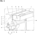
FIG. 3 is a partially-cut perspective diagram showing that a water tank shown inFIG. 1 is installed at a door; -
FIG. 4 is a cross-sectional diagram showing that a water tank shown inFIG. 1 is installed at a refrigerator compartment door; and -
FIG. 5 is a perspective diagram showing a passage to a pump and icemaker from a water tank shown inFIG. 1 . - Reference will now be made in detail to a refrigerator according to the preferred embodiment of the present invention, examples of which are illustrated in the accompanying drawings. Although description will now be given in detail according to exemplary embodiments disclosed herein with reference to the accompanying drawings, the embodiments and drawings are used to help the understanding of the present invention.
- Moreover, to help the understanding of the present invention, s the accompanying drawings may be illustrated in a manner of exaggerating sizes of some components instead of using a real scale.
- Thus, the present invention is non-limited to the following embodiment, and it is intended that the present invention covers the modifications and variations of this invention provided they come within the scope of the appended claims and their equivalents.
- First of all, an overall configuration of a refrigerator according to a preferred embodiment of the present invention is described with reference to
FIG. 1 . In the following description, a top-freezer refrigerator having a freezer compartment located provided to a top and a refrigerator compartment provided to a bottom is taken as an example. - For clarity of the following description, a refrigerator door direction shall be represented as a front and a freezer/refrigerator compartment direction shall be represented as a rear. Moreover, left and right directions are described with reference to viewing a refrigerator in a door direction.
- A
freezer compartment 21 is provided to a top side of acabinet 2 configuring an exterior of arefrigerator 1, and arefrigerator compartment 23 is provided to a bottom side of thecabinet 2. Afreezer compartment door 3 configured to open/close thefreezer compartment 21 is rotatable coupled to thefreezer compartment 21. And, arefrigerator compartment door 4 configured to open/close therefrigerator compartment 23 is rotatably coupled to therefrigerator compartment 23. - Meanwhile, an
icemaker 7 is installed at thefreezer compartment door 3 and a dispenser 9 (seeFIG. 2 ) is installed at therefrigerator compartment door 4. Although theicemaker 7 can be installed within thefreezer compartment 21 or at thefreezer compartment door 3, the following description is made by taking an example of installing theicemaker 7 at thefreezer compartment door 3. - A
water tank 5 configured to receive water therein is removably provided to therefrigerator compartment door 4. Apump housing 8 is provided under thewater tank 5, and a pump is installed within thepump housing 8. - The water of the
water tank 5 can be provided to the dispenser and/or theicemaker 7 selectively or simultaneously. Namely, a passage for supplying the water of thewater tank 5 to the dispenser is provided between thewater tank 5 and the dispenser and a passage for supplying the water of thewater tank 5 to theicemaker 7 is provided between thewater tank 5 and theicemaker 7. [Specific passage structures shall be described later.] - In some implementations, the
water tank 5 is preferably located over the dispenser. Therefore, the water supply from thewater tank 5 to the dispenser can be achieved by gravity, i.e., free fall without using a separate pump. On the other hand, since theicemaker 7 is provided to thefreezer compartment door 3, it is preferable that the water of thewater tank 5 is sent to theicemaker 7 using a pump. An automatic icemaker is preferably used as theicemaker 7, by which the present invention is non-limited. - The
water tank 5, thepump housing 8 and thedispenser 9 are described with reference toFIG. 2 as follows. - First of all, the water of the
water tank 5 should be supplied to each of thedispenser 9 and apump 6 within thepump housing 8. - Hence, a
first outlet 58 and asecond outlet 57 are provided to thewater tank 5. And, the water is supplied to thedispenser 9 and thepump 6 through thefirst outlet 58 and thesecond outlet 57, respectively. - While the
water tank 5 is separate from therefrigerator compartment door 4, since thefirst outlet 58 and thesecond outlet 57 are blocked or closed, the water of thewater tank 5 is not discharged externally. - If a user couples the
water tank 5 to therefrigerator compartment door 4, thefirst outlet 58 of thewater tank 5 is connected to the passage to thedispenser 9 and thesecond outlet 57 is connected to the passage to thepump 6. [Specific passage opening/closing structures of the first and second outlets shall be described later.] - The respective components are described in detail as follows.
- First of all, the
water tank 5 is described. - Water is received in the
water tank 5. The water of thewater tank 5 can be supplied to thedispenser 9 and theicemaker 7. - To this end, an inlet (not shown) for putting external water into the
water tank 5 may be provided to thewater tank 5. Acap 56 for selectively opening/closing the inlet can be provided. And, thefirst outlet 58 for supplying water to thedispenser 9 may be provided to thewater tank 5. And, thesecond outlet 57 for supplying water to theicemaker 7 may be provided to thewater tank 5. - In some implementations, although the
water tank 5 may be formed inte3grally, it may be configured in a manner of including acontainer 52 and acover 54. For clarity of the following description, thewater tank 5 is described in a manner of being divided into thecontainer 52 and thecover 52. - For example, the
water tank 5 may include thecontainer 52 having a prescribed space configured to receive water therein. Thecover 54 may be removably coupled to a top side of thecontainer 52. In order for a user to put water into thecontainer 52, acap 56 may be removably provided to thecover 54. - A shape of the
container 52 is non-limited but may preferably have an approximately hexahedral shape of which inside is empty. And, it is preferable that a width (i.e., right-to-left length) of thecontainer 52 may be substantially equal to or slightly smaller than a width of the refrigerator compartment door. A depth (i.e., front-to-rear length) and thickness (i.e., top-to-bottom length) of thecontainer 52 can be selected appropriately. - Meanwhile, the
first outlet 58 and thesecond outlet 57 are provided to thecontainer 52. It is preferable that each of the first andsecond outlets container 52. Water is supplied to thedispenser 9 through thefirst outlet 58. And, Water is supplied to thepump 6 within thepump housing 8 through thesecond outlet 57. - Preferably, the
first outlet 58 is provided to the center of thecontainer 52 approximately. Namely, as water is supplied to thedispenser 9 through thefirst outlet 58, thedispenser 9 is generally located at the center of therefrigerator compartment door 4. Hence, if thefirst outlet 58 is disposed at the center of thecontainer 52, it is able to decrease a length of a passage. - Preferably, the
second outlet 57 may be disposed in a manner of inclining to one side from the center of thecontainer 52, and more preferably, a portion at which the hinge shaft of therefrigerator compartment door 4 is installed. Namely, thepump 6 plays a role in sending water of thewater tank 5 to theicemaker 7 provided to thefreezer compartment door 3. Yet, it is preferable to decrease the length of the passage connected to theicemaker 7 from thepump 6. To this end, thepump 6 may be preferably disposed to one side of therefrigerator compartment door 4, and more preferably, to a place adjacent to a portion at which the hinge shaft is installed. Therefore, it is preferable that thesecond outlet 57 connected to thepump housing 8 having thepump 6 received therein is also disposed in a manner of inclining in a direction of the hinge shaft. - Meanwhile, the
first outlet 58 is preferably provided in a manner of inclining downward in a front direction (e.g., an outdoor direction) of therefrigerator compartment door 4. This is because thedispenser 9 connected to thefirst outlet 58 is provided in front of therefrigerator compartment door 4. Preferably, thesecond outlet 57 is provided in a manner of having the substantially same inclination of thefirst outlet 58. Namely, if thefirst outlet 58 and thesecond outlet 57 differ from each other in inclination, it is not easy to couple thewater tank 5 to therefrigerator compartment door 4. - The inclinations of the first and
second outlets - First of all, although each of the first and
second outlets second outlets water tank 5 in a horizontal direction without interfering with other structures such as a rack, a basket and the like within therefrigerator compartment door 4. Yet, in this case, as the first andsecond outlets refrigerator compartment door 4. - Moreover, if the first and
second outlets water tank 5 is installed at therefrigerator compartment door 4, interference with other structures of therefrigerator compartment door 4 is generated. Although the height of thewater tank 5 can be reduced to avoid such interference, the capacity or volume of thewater tank 5 is disadvantageously reduced. - Yet, if each of the first and
second outlets water tank 5 at therefrigerator compartment door 4 by minimizing the interference with other structures within therefrigerator compartment door 4 without reducing the capacity of thewater tank 5 as well as increasing the thickness of therefrigerator compartment door 4. - Meanwhile, the
first outlet 58 and thesecond outlet 57 are preferably co-located on the front side of thewater tank 5. Namely, when thefirst outlet 58 and thesecond outlet 57 are viewed in a lateral direction of thewater tank 5, they are preferably located on the same line. This is because, if thefirst outlet 58 and thesecond outlet 57 are located on the front side and the rear side of thewater tank 5, respectively, it is not easy to couple thewater tank 5 to therefrigerator compartment door 4. - Namely, when the
water tank 5 is coupled to therefrigerator compartment door 4, thewater tank 5 interferes with racks of the refrigerator compartment door, which may be present above or below of the water tank, whereby the coupling is not facilitated. Moreover, if thefirst outlet 58 and thesecond outlet 57 are not located on the front side of thewater tank 5, the passage from thewater tank 5 to therefrigerator compartment door 4 increases. - The coupling between the
first outlet 58 and thedispenser 9 is described as follows. - First of all, a
valve 59 is coupled to thefirst outlet 58 of thewater tank 5, and thevalve 59 is coupled to thedispenser 9 through adispenser connector 92. If a user pushes alever 94, thevalve 59 becomes open so that the water of thewater tank 5 can be externally discharged through thefirst outlet 58 and thevalve 59. As the structure of thedispenser 9 is popularly known and used, its details shall be omitted. For convenience and facilitation of assembly, an inclination angle of thefirst outlet 58 of thewater tank 5 may be equal to that of thedispenser connector 92. - Structures of the
second outlet 57 of thewater tank 5 and thepump housing 8 are described as follows. - First of all, the
pump housing 8 is described. - The
pump housing 8 is coupled to an inside of therefrigerator compartment door 4. Thepump 6 is provided within thepump housing 8. Thepump housing 8 may include afront housing 8a and arear housing 8b provided in rear of thefront housing 8a. Thefront housing 8a may preferably have an approximately hexahedral shape. Preferably, therear housing 8b has a top-bottom height and a right-left width slightly greater than those of thefront housing 8b. Therear housing 8b may play a role in supporting a portion of thewater tank 5 installed over therear housing 8b [SeeFIG. 3 ]. - Meanwhile, it is preferable that a passage connecting an entrance of the
pump 6 and thesecond outlet 57 is protected. To this end, a connectingmember 80 may be provided between thepump housing 8 and therefrigerator compartment door 4. - A passage, e.g., a
tube 62 may be received in the connectingmember 80. Thetube 62 can connect the entrance of thepump 6 and aconnector 86 provided to the inner door of the refrigerator compartment door 4 [SeeFIG. 4 ]. - The connecting
member 80 of thepump housing 8 is described as follows. - First of all, a tube joint 87 is coupled to an outside of the
front housing 8a, atube guide 88 is coupled to the tube joint 87, and theconnector 86 is coupled to thetube guide 88. - A
gasket ring cover 82 is coupled to an inside of theconnector 86, and agasket ring 84 is received in an inner surface of thegasket ring cover 82. - Meanwhile, an
annular ring 572, aspring 574 and ashaft 576 are provided within thesecond outlet 57. [Specific removable structures of thesecond outlet 57 of thewater tank 5 and the connectingmember 80 of thepump housing 8 shall be described later.] - With reference to
FIG. 2 andFIG. 3 , a structure that thewater tank 5 is coupled to therefrigerator compartment door 4 is described as follows. - First of all, the
refrigerator compartment door 4 is described. Generally, therefrigerator compartment door 4 includes anouter door 22 and an inner door (e.g., a door liner) 24 coupled to theouter door 22. - A
top cap deco 28 is coupled to the top sides of the outer andinner doors outer door 22, theinner door 24, thetop cap deco 26 and the bottom cap deco is filled up with aninsulator 26. - Meanwhile, a
seat portion 42 projected in an approximately horizontal direction is provided to theinner door 24. Thewater tank 5 is put on a top surface of theseat portion 42. Thepump housing 8 is coupled to a bottom side of theseat portion 42. Therear housing 8b of thepump housing 8 is projected from theseat portion 42 in a rear direction, thereby playing a role in supporting thewater tank 5. - A
dispenser connector 92 is coupled to an approximate center of theseat portion 42 of theinner door 24. And, thevalve 59 coupled to thefirst outlet 58 of thewater tank 5 is inserted in thedispenser connector 92. - A
gasket ring cover 82 may be provided next to thedispenser connector 92. Thesecond outlet 57 of thewater tank 5 is inserted in thegasket ring cover 82. And the connectingmember 80 is connected between thegasket ring cover 82 and thefront housing 8a. - Meanwhile, in order to facilitate the
water tank 4 to be seated on therefrigerator compartment door 4, it is preferable that an inclination angle of thefirst outlet 58 in the front direction is equal to that of thesecond outlet 57 in the front direction. And, it is preferable that an inclination angle of thedispenser connector 92 coupled to thefirst outlet 58 is equal to that of thegasket ring cover 82 coupled to thesecond outlet 57. - Moreover, in order to facilitate the
water tank 5 to be attached to or detached from therefrigerator compartment door 4, an additional structure is provided preferably. Such a structure is described as follows. - First of all, a pair of
support members 500 are preferably provided to an inside of therefrigerator compartment door 4, and aguide member 400 attached to or detached from thesupport member 500 is preferably provided to each of both lateral sides of thewater tank 5. - The support member 50 is preferably provided to an inside of each of both ends of the
inner door 24 with a prescribed thickness. A door dike for seating a rack, a basket or the like is provided to each of both sides of theinner door 24, and thesupport member 500 is more preferably provided to the door dike. - The
support member 500 preferably includes atop surface portion 502 formed to have a prescribed inclination, arear surface portion 506 descending at a prescribed angle from a rear of thetop surface portion 502, and afront surface portion 504 descending at a prescribed angle from a front of thetop surface portion 502. - And, an inclination angle A of the
top surface portion 502 is preferably smaller than an inclination angle of thesecond outlet 57 of thewater tank 5. For example, the inclination angle A of thetop surface portion 502 preferably has an about 35° with a horizontal plane. And, it is preferable that thefront surface portion 504 is approximately vertical. - Meanwhile, the
guide member 400 provided to thewater tank 5 preferably has a shape corresponding to that of thesupport member 500. - The guide member preferably includes a
center portion 402, arear portion 406 and afront portion 404. Moreover, a projectedportion 408 further extending in front direction is preferably provided in front of thefront portion 404 of theguide member 400. - The inclination angles of the
center portion 402, therear portion 406 and thefront portion 406 of theguide member 400 preferably correspond to thetop surface portion 502, therear surface portion 506 and thefront surface portion 506 of thesupport member 500, respectively. Hence, if thewater tank 5 is installed at therefrigerator compartment door 4, thecenter portion 402, therear portion 406 and thefront portion 406 of theguide member 400 are supported by thetop surface portion 502, therear surface portion 506 and thefront surface portion 506 of thesupport member 500, respectively. - Meanwhile, in a general use state of the refrigerator, the
water tank 5 is coupled to therefrigerator compartment door 4. In this state, if thewater tank 5 is empty, a user opens thecap 56 of thewater tank 56 and then puts water into thewater tank 5. In case that a user cleans thewater tank 5, thewater tank 5 is separated from therefrigerator compartment door 4. - In the state that the
water tank 5 is separated from therefrigerator compartment door 4, the first andsecond outlets water tank 5 should be blocked so that the water of thewater tank 5 is not discharged externally. In the state that thewater tank 5 is coupled to therefrigerator compartment door 4, the first andsecond outlets water tank 5 should be open so that water can be supplied to thedispenser 9 and thepump 6. - Yet, the
valve 59 is installed at thefirst outlet 58 of thewater tank 5. Thevalve 59 is normally in a closed state. If a user pushes alever 94 of thedispenser 9, thevalve 59 is open. Namely, as thevalve 59 is coupled to thefirst outlet 58, a separate passage open/close structure is not necessary. Thevalve 59 is generally used for thedispenser 9 and its details shall be omitted. - On the other hand, in the state that the
water tank 5 is separated from therefrigerator compartment door 4, thesecond outlet 57 of thewater tank 5 should have a closed passage. In the state that thewater tank 5 is coupled to therefrigerator compartment door 4, thesecond outlet 57 of thewater tank 5 should have an open passage. In the state that thewater tank 5 is coupled to therefrigerator compartment door 4, the passage to the entrance of thepump 6 from thewater tank 5 is in an open state. And, by the operation of the pump, the water on the entrance side of the pump is supplied to theicemaker 7. - With reference to
FIG. 2 andFIG. 4 , the open/closed structure of the passage of thesecond outlet 57 of thewater tank 5 is described as follows. - First of all, the structure of the
second outlet 57 of thewater tank 5 is described in detail. - A switch capable of selectively opening/closing the
second outlet 57 can be provided to thesecond outlet 57. In the state that thewater tank 5 is separated from therefrigerator compartment door 4, the switch can close thesecond outlet 57. In the state that the water tank is coupled to therefrigerator compartment door 4, the switch can open thesecond outlet 57. - One embodiment of the switch is described as follows.
- First of all, the
second outlet 57 of the switch is described. A small-diameter portion 57b having a small diameter is provided to a tip of thesecond outlet 57 of thewater tank 5. A protrudingportion 57c protruding inward is provided to a portion from which the small-diameter portion 57b begins. Aspring 574 is installed within the small-diameter portion 57b, and the protrudingportion 57c plays a role in supporting a top potion of thespring 574. - A
shaft 576 is installed in the small-diameter portion 57b. Theshaft 576 includes ahead portion 576a having a big diameter and abody portion 576b extending downward from thehead portion 576a. And, anannular ring 572 is put on thehead portion 576a, whereby water leakage can be prevented. - The
body portion 576b is configured in a manner that 4 thin panel-type members alternate one another in a radial direction at the center of theshaft 576 and has a cross-shaped cross-section. Space among the 4 panel-type members becomes a passage through which water passes. Acatch portion 576c extending in a radial direction is provided to a bottom end of thebody portion 576b, and a bottom end of thespring 574 is supported by thecatch portion 576c. - Next, the structure of the coupling part of the
pump housing 8 is described. - The
connector 86 may be provided to theinner door 24 of therefrigerator compartment door 4. Thesecond outlet 57 can be selectively connected to theconnector 86. When thesecond outlet 57 is coupled to theconnector 86, water leakage can be prevented preferably. Hence, thegasket ring 84 can be provided to an inside of theconnector 86. Moreover, thegasket ring 84 can be supported by thegasket ring cover 82. - One end of the
tube guide 88 can be connected to theconnector 86, and the other end of thetub guide 88 can be connected to the tube joint 87 coupled to thepump housing 8. And, a passage (e.g., a tube) connected to the entrance of thepump 6 may be connected to theconnector 86. - This is described in detail as follows.
- First of all, the tube joint 87 is coupled to an outside of the
pump housing 8, and thetube guide 88 is coupled to the other side of the tube joint 87. And, theconnector 86 is coupled to the other end of thetube guide 88. - The
connector 86 includes a small-diameter portion 86a inserted and coupled to an inside of thetube guide 88, and a projectedportion 86c projected upward is provided to a top surface of the small-diameter portion 86a. A large-diameter portion 86b having a diameter greater than that of the small-diameter portion 86a is formed on the small-diameter portion 86a. And, a tube-expandingportion 86b extending in a radial direction by inclining upward is formed on the large-diameter portion 86b. - Meanwhile, the
gasket ring cover 82 is coupled to the inner surfaces of the large-diameter portion 86b and the tube-expandingportion 86d of theconnector 86. Hence, thegasket ring cover 82 approximately has the shape corresponding to the large-diameter portion 86b and the tube-expandingportion 86d of theconnector 86. - The
gasket ring cover 82 includes aportion 82a corresponding to the large-diameter portion 86b of theconnector 86 and aportion 82b corresponding to the tube-expandingportion 86b. And, thegasket ring 84 is received in an inner bottom of thegasket ring cover 82. And, a protrudingportion 82c protruding inward is formed at a prescribed position of thegasket ring cover 82 so as to prevent thegasket ring 84 from being pulled out. - Meanwhile, the
tip 82b of thegasket ring cover 82 is preferably coupled to a front side of theinner door 24 and thetip 86d of theconnector 86 of the connectingmember 80 is preferably coupled to a rear side of theinner door 24. - The first outlet is provided in a manner of inclining in a front direction. Accordingly, the
gasket ring cover 82 and theconnector 86 are preferably installed to have the same inclination angle. - The attaching/detaching process for the
second outlet 57 of thewater tank 5 and the connectingmember 80 of thepump housing 8 is described as follows. - First of all, with reference to
FIG. 4 (a) , a state that thewater tank 5 is separated from therefrigerator compartment door 4 is described. - In this state, the
spring 574 installed within thesecond outlet 57 pulls theshaft 576 downward. Hence, theannular ring 572 provided to thehead portion 576a of theshaft 576 closely comes in contact with the protrudingportion 57c of thesecond outlet 57, whereby water is not discharged out of thesecond outlet 57. - Next, with reference to
FIG. 4 (b) , a state that thewater tank 5 is coupled to therefrigerator compartment door 4 is described. - If the
water tank 5 is coupled to therefrigerator compartment door 4, thesecond outlet 57 of thewater tank 5 is inserted in thegasket ring cover 82. - Once the insertion is complete, the projected
portion 86c of theconnector 86 pushes theshaft 576 upward. Once theshaft 576 is moved upward, thehead portion 576a of theshaft 576 is spaced apart from the protrudingportion 57c of thesecond outlet 57. - Therefore, there is a gap between the
head portion 576a of theshaft 576 and the protrudingportion 57c, whereby water of thewater tank 5 is discharged in the direction of thetube 62 through the gap. In doing so, as the small-diameter portion 57b of thesecond outlet 57 of thewater tank 5 is already inserted in thegasket ring 84, the water leakage can be prevented by thegasket ring 84. - With reference to
FIG. 3 andFIG. 5 , the passages from thewater tank 5 to thedispenser 9 and theicemaker 7 are described as follows. - First of all, the passage from the
water tank 5 to thedispenser 9 is described. - The
water tank 5 is located above thedispenser 9. Thevalve 59 connected to thefirst outlet 58 of thewater tank 5 is coupled to adispenser connector 92. The passage between thewater tank 5 and thedispenser 9 is relatively short. - Moreover, as the
water tank 5 is located above thedispenser 9, a separate pump is unnecessary. If a user pushes thelever 94, thevalve 59 is open and the water of thewater tank 5 is discharged to thedispenser 9 by gravity. - Next, the passage from the
water tank 5 to theicemaker 7 is described with reference to FIG. 6. - The
water tank 5 is provided to therefrigerator compartment door 4. Yet, since theicemaker 7 is provided to thefreezer compartment door 3 located above thewater tank 5, thepump 6 is required in order to send the water of thewater tank 5 to theicemaker 7. Preferably, the supply of water to theicemaker 7 is performed selectively. Namely, water is preferably supplied to theicemaker 7 when an ice tray is empty. Hence, although theicemaker 7 is located below thewater tank 5, thepump 6 is used preferably. - The passage from the
water tank 5 to theicemaker 7 includes a passage from thewater tank 5 to theentrance 6a of thepump 6 and a passage from theexit 6b of thepump 6 to theicemaker 7. A substantial passage from thewater tank 5 to theentrance 6a of thepump 6 is thetube 62 starting from thesecond outlet 57 of thewater tank 5 up to theentrance 6a of thepump 6 via the connector 36. - Next, the passage connecting the
exit 6b of thepump 6 to theicemaker 7 is described. - The
pump 6 is installed at therefrigerator compartment door 4, and theicemaker 7 is installed at thefreezer compartment door 3. Hence, the passage from thepump 6 to theicemaker 7 should connect the refrigerator compartment to the freezer compartment. - The connection of the passage from the refrigerator compartment to the freezer compartment preferably uses a
hinge shaft 210 of ahinge member 200. For example, the passage from the refrigerator compartment to the freezer compartment is connected in a manner of using a hollow shaft as thehinge shaft 210 and also using ahollow portion 212 of thehinge shaft 210. - This is described in detail as follows.
- First of all, the passage from the
exit 6b of thepump 6 to theicemaker 7 preferably uses thetube 64 having flexibility. To protect the tube, thetube 64 is preferably received in atube guide 100. Thetube guide 100 includes a hollow pipe capable of receiving the tube therein and preferably uses a material having relative durability. - The
tube guide 100 is connected between thepump housing 8 and the hinge shat 210. And. Anothertube guide 110 is preferably connected between thehinge shaft 210 and theicemaker 7. Thetube guide 100 may directly pass through thehollow portion 212 of thehinge shaft 210. Or, since thehinge shaft 210 is generally formed of metallic material, thetube 64 can directly pass through thehollow portion 212 of thehinge shaft 210 without using thetube guide 100 for thehollow portion 212 of thehinge shaft 210. - Meanwhile, the
tube guide 100 from thepump housing 8 to thehinge shaft 210 is preferably buried in the insulator of the refrigerator compartment door. Moreover, thetube guide 110 from thehinge shaft 210 to theicemaker 7 is preferably buried in the insulator of the freezer compartment door. - With reference to
FIG. 2 andFIG. 3 , an operation of thewater tank 5 of the refrigerator according to the present embodiment is described as follows. - First of all, the
water tank 5 is removable from therefrigerator compartment door 4. For example, when thewater tank 5 is cleaned, a user separates thewater tank 5 from therefrigerator compartment door 4. While thewater tank 5 is separated, water is not discharged through the first andsecond outlets water tank 5. - This is because the
first outlet 58 is in a state that the passage is blocked by thevalve 59 coupled to thefirst outlet 58. And, thesecond outlet 57 has the passage blocked by theannular ring 572, thespring 574 and theshaft 576 installed within thesecond outlet 57. - Once the user finishes the cleaning of the
water tank 5, the user installs thewater tank 5 at therefrigerator compartment door 4 again. - In doing so, the user can easily seat the
water tank 5 on therefrigerator compartment door 4 without interference with other components such as a rack, a basket and the like. This is because the first andsecond outlets water tank 5 are projected downward at the same inclination angle in a front direction. Moreover, when thefirst outlet 58 and thesecond outlet 57 are viewed in a lateral direction of thewater tank 5, they are located on the same line. Hence, thewater tank 5 can be seated more conveniently and easily. - Once the
water tank 5 is seated on therefrigerator compartment door 4, the water of thewater tank 5 can be supplied to thedispenser 9 and/or theicemaker 7. As the passage of thevale 59 coupled to thefirst outlet 58 is blocked even in the state that thewater tank 5 is seated on therefrigerator compartment door 4, water is not discharged through thefirst outlet 58. Yet, if a user pushes thelever 94 of thedispenser 9, an open signal is sent to thevalve 59 so as to open thevalve 59. As thevalve 59 is open, water is discharged to thedispenser 9. - Meanwhile, while the
water tank 5 is seated on therefrigerator compartment door 4, water of thewater tank 5 can be supplied to the entrance of thepump 6 through thesecond outlet 57. Yet, if thepump 6 does not operate, the water reaches the pump entrance side only. In this state, if a drive signal of the pump is sent to thepump 6 from theicemaker 7, thepump 6 operates to supply water to theicemaker 7. - Meanwhile, if the water of the
water tank 5 is used all in the state that while thewater tank 5 is seated on therefrigerator compartment door 4, a user can open thecap 56 of thewater tank 5 and put water into thewater tank 5 through thecap 56. - As described above, according to the present invention, water can be advantageously supplied to the
dispenser 9 and theicemaker 7 using thesingle water tank 5, whereby convenience in suing the refrigerator is enhanced. - And, owing to the structures of the first and
second outlets water tank 5, a user can conveniently install/separate the water tank at/from therefrigerator compartment door 4. Moreover, the passage from thewater tank 5 to thedispenser 9 and theicemaker 7 can be minimized advantageously. - The matter of the above-described embodiment is identically applicable to other undescribed parts. Moreover, the technical matter described in one embodiment is identically applicable to another embodiment if it is not contrary mutually, unless otherwise specifically stated.
- The top-freezer refrigerator is exemplarily described in the above embodiment, by which the present invention is non-limited. For example, the principle of the present invention is applicable to a bottom-freezer refrigerator. In this case, a water tank and a dispenser are preferably installed at a refrigerator compartment door and an icemaker is preferably installed in a freezer compartment. Although the water tank is located above the icemaker installed in the freezer compartment, it is preferable that water is selectively supplied to the icemaker. Hence, a pump is used preferably. Particularly, an auto-icemaker preferably uses a pump.
- Moreover, the principle of the present invention is applicable to a side-by-side refrigerator. In this case, a water tank and a dispenser are preferably installed at a refrigerator compartment door and an icemaker is preferably installed in a freezer compartment. The icemaker installed in the freezer compartment may be installed higher or lower than the water tank. Since it is preferable that water is selectively supplied to the icemaker irrespective of the water tank installation height, a pump is used preferably as well.
- It will be appreciated by those skilled in the art that various modifications and variations can be made in the present invention without departing from the spirit or scope of the inventions. As the present features may be embodied in several forms without departing from the characteristics thereof, it should also be understood that the above-described embodiments are not limited by any of the details of the foregoing description, unless otherwise specified, but rather should be considered broadly within its scope as defined in the appended claims, and therefore all changes and modifications that fall within the metes and bounds of the claims, or equivalents of such metes and bounds, are therefore intended to be embraced by the appended claims.
Claims (15)
- A refrigerator having a freezer compartment (21) and a refrigerator compartment (23), the refrigerator comprising:an icemaker (7) provided in the freezer compartment or at a freezer compartment door (3) configured to open/close the freezer compartment (21);a dispenser (9) provided at a refrigerator compartment door (4) configured to open/close the refrigerator compartment (23);a water tank (5) provided at the refrigerator compartment door (4); anda pump (6) configured to pump water from the water tank (5) to the icemaker (7);wherein the water tank (5) has an inlet for putting in water, a first outlet (58) for supplying water to the dispenser (9), and a second outlet (57) for supplying water to the pump (6).
- The refrigerator of claim 1, wherein the first outlet (58) and the second outlet (57) extend downward and/or are inclined at the same angle to a horizontal plane.
- The refrigerator of claim 1 or 2, wherein the first outlet and the second outlet extend in parallel to each other.
- The refrigerator according to any one of the preceding claims, further comprising a switch configured to selectively open and close the second outlet (57).
- The refrigerator of claim 4, wherein if the water tank (5) is separated from the refrigerator compartment door (4), the switch is configured to close the second outlet (57) and/or wherein if the water tank (5) is installed at the refrigerator compartment door (4), the switch is configured to open the second outlet (57).
- The refrigerator according to any one of the preceding claims, further comprising a pump housing (8) accommodating the pump (6) therein and a connecting member (80) for detachably connecting the second outlet (57) and the pump housing (8).
- The refrigerator of claim 6, wherein the connecting member (80) includes a connector (86), into which the second outlet (57) of the water tank (5) is insertable.
- The refrigerator of claim 7, wherein the connector (86) comprises a small-diameter portion (86a), a large-diameter portion (86b) and an expanding portion (86d), wherein the large-diameter portion (86b) is arranged between the small-diameter portion (86a) and the expanding portion (86d), and wherein the large-diameter portion (86b) has a larger diameter than the small-diameter portion (86a) and the expanding portion (86d) has a diameter expanding from the diameter of the large-diameter portion (86b).
- The refrigerator of claim 8, wherein the switch is movable in an insertion direction of the second outlet (57), wherein the connector (80) includes a protruding portion (86c) provided at the small-diameter portion (86a) and protruding in the insertion direction of the second outlet (57) in order to operate the switch of the second outlet.
- The refrigerator of any one of claims 7 to 9, wherein a gasket ring cover (82) including a gasket ring (84) is provided in the connector (86).
- The refrigerator of claim 10, wherein an inner door (24) of the refrigerator compartment door (4) is arranged between the gasket ring cover (82) and the connector (86).
- The refrigerator of claim 11, further comprising a tube (64) connecting the pump (6) and the icemaker (7), wherein the tube (64) passes through a hollow portion of a hinge shaft of the refrigerator compartment door (4).
- The refrigerator according to any one of the preceding claims, wherein the refrigerator compartment door (4) has a support member (500) for detachably supporting the water tank (5)and wherein the water tank (5) has a guide member (400) to be supported by the support member.
- The refrigerator of claim 13, wherein the support member (500) comprises a top surface portion (502) being inclined at a prescribed angle with respect to a horizontal plane, a rear surface portion (506) descending at a prescribed angle from one end of the top surface portion (502), and a front surface portion (504) descending at a prescribed angle from the other end of the top surface portion (502), and wherein the guide member (400) comprises a center portion (402), a rear portion (406) and a front portion (404) corresponding to the top surface portion (502), the rear surface portion (506) and the front surface portion (504) of the support member (500), respectively.
- The refrigerator of claim 14, wherein the second outlet (57) of the water tank (5) is inclined with respect to a horizontal plane and an angle of inclination of the top surface portion (502) of the support member (500) is smaller than an angle of inclination of the second outlet (57) of the water tank (5).
Priority Applications (1)
| Application Number | Priority Date | Filing Date | Title |
|---|---|---|---|
| EP23202429.9A EP4279842A3 (en) | 2018-08-01 | 2019-07-31 | Refrigerator |
Applications Claiming Priority (1)
| Application Number | Priority Date | Filing Date | Title |
|---|---|---|---|
| KR20180089933 | 2018-08-01 |
Related Child Applications (1)
| Application Number | Title | Priority Date | Filing Date |
|---|---|---|---|
| EP23202429.9A Division EP4279842A3 (en) | 2018-08-01 | 2019-07-31 | Refrigerator |
Publications (2)
| Publication Number | Publication Date |
|---|---|
| EP3604992A1 true EP3604992A1 (en) | 2020-02-05 |
| EP3604992B1 EP3604992B1 (en) | 2023-10-11 |
Family
ID=67514413
Family Applications (2)
| Application Number | Title | Priority Date | Filing Date |
|---|---|---|---|
| EP19189410.4A Active EP3604992B1 (en) | 2018-08-01 | 2019-07-31 | Refrigerator |
| EP23202429.9A Pending EP4279842A3 (en) | 2018-08-01 | 2019-07-31 | Refrigerator |
Family Applications After (1)
| Application Number | Title | Priority Date | Filing Date |
|---|---|---|---|
| EP23202429.9A Pending EP4279842A3 (en) | 2018-08-01 | 2019-07-31 | Refrigerator |
Country Status (7)
| Country | Link |
|---|---|
| US (3) | US11112159B2 (en) |
| EP (2) | EP3604992B1 (en) |
| KR (1) | KR20200014706A (en) |
| CN (1) | CN110806048B (en) |
| AU (1) | AU2019210604B2 (en) |
| BR (1) | BR102019016001A2 (en) |
| MX (1) | MX2019009081A (en) |
Cited By (1)
| Publication number | Priority date | Publication date | Assignee | Title |
|---|---|---|---|---|
| EP4027089A1 (en) * | 2021-01-06 | 2022-07-13 | LG Electronics Inc. | Refrigerator |
Families Citing this family (3)
| Publication number | Priority date | Publication date | Assignee | Title |
|---|---|---|---|---|
| US11112159B2 (en) * | 2018-08-01 | 2021-09-07 | Lg Electronics Inc. | Refrigerator |
| BR102019015737A2 (en) | 2018-08-01 | 2020-02-18 | Lg Electronics Inc. | REFRIGERATOR |
| JP2023095128A (en) * | 2021-12-24 | 2023-07-06 | アクア株式会社 | refrigerator |
Citations (9)
| Publication number | Priority date | Publication date | Assignee | Title |
|---|---|---|---|---|
| GB2118700A (en) * | 1982-03-09 | 1983-11-02 | Philips Nv | Ice cube maker for a refrigerator |
| KR20050117830A (en) * | 2004-06-11 | 2005-12-15 | 엘지전자 주식회사 | Apparatus for supplying water to refrigerator |
| DE102007023304A1 (en) * | 2007-05-16 | 2008-11-20 | Stricker, Heinz, Dipl.-Ing. | Refrigerator-freezer combination comprises refrigerator and freezer, which are arranged adjacent to each other, where refrigerator and freezer both have housing and cooling device, and freezer is provided with ice-water tap unit |
| WO2011019202A2 (en) * | 2009-08-11 | 2011-02-17 | Lg Electronics Inc. | Refrigerator |
| EP2600085A2 (en) * | 2011-11-29 | 2013-06-05 | Samsung Electronics Co., Ltd | Refrigerator |
| US20160083241A1 (en) * | 2014-09-23 | 2016-03-24 | Dongbu Daewoo Electronics Corporation | Functional beverage making and dispensing from a refrigerator |
| KR20170096326A (en) * | 2016-02-16 | 2017-08-24 | 엘지전자 주식회사 | A refrigerator |
| KR20180089933A (en) | 2017-02-01 | 2018-08-10 | 주식회사 효성 | Apparatus for coagulating doped solution of precursor for a carbon fiber |
| EP3406992A1 (en) * | 2017-05-26 | 2018-11-28 | LG Electronics Inc. | Refrigerator |
Family Cites Families (34)
| Publication number | Priority date | Publication date | Assignee | Title |
|---|---|---|---|---|
| US2781153A (en) | 1955-12-14 | 1957-02-12 | Gen Electric | Liquid cooler for refrigerating apparatus |
| JPS63254367A (en) * | 1987-04-13 | 1988-10-21 | ホシザキ電機株式会社 | Ice dispenser |
| JPH0611228A (en) | 1992-06-29 | 1994-01-21 | Hitachi Ltd | Refrigerator with automatic ice machine |
| JPH07260303A (en) | 1994-03-28 | 1995-10-13 | Matsushita Refrig Co Ltd | Icemaker |
| US5737932A (en) | 1995-10-31 | 1998-04-14 | Samsung Electronics Co., Ltd. | Refrigerator having controller for supplying water from a reservoir to either an ice maker or an outside dispenser |
| US5813246A (en) | 1995-12-05 | 1998-09-29 | Samsung Electronics Co., Ltd. | Water dispenser for a refrigerator |
| KR970075794A (en) * | 1996-05-16 | 1997-12-10 | 배순훈 | External water supply of water tank for water dispenser |
| JP2002115960A (en) | 2000-10-04 | 2002-04-19 | Hitachi Ltd | Refrigerator |
| JP2006162224A (en) | 2004-12-10 | 2006-06-22 | Toshiba Corp | Water supply device |
| ITTO20050164A1 (en) | 2005-03-15 | 2006-09-16 | Eltek Spa | REFRIGERATION APPARATUS WITH A LIQUID FEEDING SYSTEM |
| US7337620B2 (en) | 2005-05-18 | 2008-03-04 | Whirlpool Corporation | Insulated ice compartment for bottom mount refrigerator |
| US9127873B2 (en) | 2006-12-14 | 2015-09-08 | General Electric Company | Temperature controlled compartment and method for a refrigerator |
| US8833100B2 (en) | 2006-12-28 | 2014-09-16 | Whirlpool Corporation | Water reservoir pressure vessel |
| KR101647374B1 (en) | 2009-05-18 | 2016-08-10 | 엘지전자 주식회사 | A refrigerator and a control method thereof |
| BRPI0902419B1 (en) | 2009-06-29 | 2021-02-02 | Electrolux Do Brasil Sa | cooler |
| KR20110026602A (en) * | 2009-09-08 | 2011-03-16 | 삼성전자주식회사 | Refrigerator |
| KR20110032167A (en) * | 2009-09-22 | 2011-03-30 | 삼성전자주식회사 | Water tank for dispenser and refrigerator having the same |
| US9797649B2 (en) | 2010-04-02 | 2017-10-24 | Hefei Midea Refrigerator Co., Ltd. | Refrigerator |
| WO2011159116A2 (en) | 2010-06-16 | 2011-12-22 | Lg Electronics Inc. | Refrigerator |
| US9021828B2 (en) * | 2011-06-28 | 2015-05-05 | General Electric Company | Ice box housing assembly and related refrigeration appliance |
| WO2013022252A2 (en) | 2011-08-09 | 2013-02-14 | 주식회사 대우일렉트로닉스 | Refrigerator |
| KR20130059987A (en) | 2011-11-29 | 2013-06-07 | 삼성전자주식회사 | Refrigerator |
| WO2013086501A2 (en) | 2011-12-09 | 2013-06-13 | Electrolux Home Products, Inc. | Refrigerator with automatic liquid dispenser |
| US9890029B2 (en) | 2011-12-09 | 2018-02-13 | Electrolux Home Products, Inc. | Refrigerator with automatic liquid dispenser |
| KR101403754B1 (en) | 2012-07-04 | 2014-06-03 | 엘지전자 주식회사 | Refrigerator |
| KR101476299B1 (en) | 2013-04-16 | 2014-12-24 | 엘지전자 주식회사 | Refrigerator |
| CN203534044U (en) * | 2013-07-02 | 2014-04-09 | 青岛海尔电冰箱(国际)有限公司 | A refrigerator with a water storage tank |
| US10808993B2 (en) * | 2014-01-07 | 2020-10-20 | Samsung Electronics Co., Ltd. | Refrigerator |
| CN104344657B (en) | 2014-03-07 | 2016-11-16 | 海尔集团公司 | Refrigerator |
| KR101612703B1 (en) | 2014-07-31 | 2016-04-15 | 엘지전자 주식회사 | Refrigerator |
| CN104613719A (en) | 2015-01-28 | 2015-05-13 | 苏州路之遥科技股份有限公司 | Drawer type aeration refrigerator freshness preservation sprayer |
| US10228184B2 (en) | 2015-06-10 | 2019-03-12 | Whirlpool Corporation | Water line guide assembly for inserting a fluid line into a fluid line valve of an appliance |
| CN107928408A (en) * | 2017-10-13 | 2018-04-20 | 青岛海尔股份有限公司 | Refrigerator |
| US11112159B2 (en) * | 2018-08-01 | 2021-09-07 | Lg Electronics Inc. | Refrigerator |
-
2019
- 2019-07-30 US US16/526,294 patent/US11112159B2/en active Active
- 2019-07-31 MX MX2019009081A patent/MX2019009081A/en unknown
- 2019-07-31 EP EP19189410.4A patent/EP3604992B1/en active Active
- 2019-07-31 KR KR1020190093101A patent/KR20200014706A/en not_active Application Discontinuation
- 2019-07-31 EP EP23202429.9A patent/EP4279842A3/en active Pending
- 2019-08-01 BR BR102019016001-2A patent/BR102019016001A2/en not_active Application Discontinuation
- 2019-08-01 AU AU2019210604A patent/AU2019210604B2/en active Active
- 2019-08-01 CN CN201910708246.7A patent/CN110806048B/en active Active
-
2021
- 2021-08-06 US US17/396,068 patent/US11781796B2/en active Active
-
2023
- 2023-09-06 US US18/242,656 patent/US20230408160A1/en active Pending
Patent Citations (9)
| Publication number | Priority date | Publication date | Assignee | Title |
|---|---|---|---|---|
| GB2118700A (en) * | 1982-03-09 | 1983-11-02 | Philips Nv | Ice cube maker for a refrigerator |
| KR20050117830A (en) * | 2004-06-11 | 2005-12-15 | 엘지전자 주식회사 | Apparatus for supplying water to refrigerator |
| DE102007023304A1 (en) * | 2007-05-16 | 2008-11-20 | Stricker, Heinz, Dipl.-Ing. | Refrigerator-freezer combination comprises refrigerator and freezer, which are arranged adjacent to each other, where refrigerator and freezer both have housing and cooling device, and freezer is provided with ice-water tap unit |
| WO2011019202A2 (en) * | 2009-08-11 | 2011-02-17 | Lg Electronics Inc. | Refrigerator |
| EP2600085A2 (en) * | 2011-11-29 | 2013-06-05 | Samsung Electronics Co., Ltd | Refrigerator |
| US20160083241A1 (en) * | 2014-09-23 | 2016-03-24 | Dongbu Daewoo Electronics Corporation | Functional beverage making and dispensing from a refrigerator |
| KR20170096326A (en) * | 2016-02-16 | 2017-08-24 | 엘지전자 주식회사 | A refrigerator |
| KR20180089933A (en) | 2017-02-01 | 2018-08-10 | 주식회사 효성 | Apparatus for coagulating doped solution of precursor for a carbon fiber |
| EP3406992A1 (en) * | 2017-05-26 | 2018-11-28 | LG Electronics Inc. | Refrigerator |
Cited By (2)
| Publication number | Priority date | Publication date | Assignee | Title |
|---|---|---|---|---|
| EP4027089A1 (en) * | 2021-01-06 | 2022-07-13 | LG Electronics Inc. | Refrigerator |
| US11927387B2 (en) | 2021-01-06 | 2024-03-12 | Lg Electronics Inc. | Refrigerator |
Also Published As
| Publication number | Publication date |
|---|---|
| US11112159B2 (en) | 2021-09-07 |
| AU2019210604B2 (en) | 2021-03-11 |
| BR102019016001A2 (en) | 2020-02-18 |
| MX2019009081A (en) | 2020-02-05 |
| US11781796B2 (en) | 2023-10-10 |
| AU2019210604A1 (en) | 2020-02-20 |
| CN110806048B (en) | 2021-08-31 |
| EP4279842A2 (en) | 2023-11-22 |
| US20210364213A1 (en) | 2021-11-25 |
| EP4279842A3 (en) | 2024-01-24 |
| KR20200014706A (en) | 2020-02-11 |
| EP3604992B1 (en) | 2023-10-11 |
| US20200041188A1 (en) | 2020-02-06 |
| CN110806048A (en) | 2020-02-18 |
| US20230408160A1 (en) | 2023-12-21 |
Similar Documents
| Publication | Publication Date | Title |
|---|---|---|
| EP3604992B1 (en) | Refrigerator | |
| CN108931095B (en) | Refrigerator with a door | |
| US8429927B2 (en) | Refrigerator | |
| US9222722B2 (en) | Refrigerator and water tank assembly for refrigerator | |
| CN102414525B (en) | Refrigerator | |
| US8800315B2 (en) | Refrigerator | |
| AU2010283082A1 (en) | Refrigerator | |
| US12038217B2 (en) | Refrigerator | |
| KR20110138777A (en) | Refrigerator | |
| KR101639442B1 (en) | Refrigerator | |
| KR100568203B1 (en) | Refrigerator | |
| JP3435149B2 (en) | refrigerator |
Legal Events
| Date | Code | Title | Description |
|---|---|---|---|
| PUAI | Public reference made under article 153(3) epc to a published international application that has entered the european phase |
Free format text: ORIGINAL CODE: 0009012 |
|
| STAA | Information on the status of an ep patent application or granted ep patent |
Free format text: STATUS: REQUEST FOR EXAMINATION WAS MADE |
|
| 17P | Request for examination filed |
Effective date: 20190731 |
|
| AK | Designated contracting states |
Kind code of ref document: A1 Designated state(s): AL AT BE BG CH CY CZ DE DK EE ES FI FR GB GR HR HU IE IS IT LI LT LU LV MC MK MT NL NO PL PT RO RS SE SI SK SM TR |
|
| AX | Request for extension of the european patent |
Extension state: BA ME |
|
| RBV | Designated contracting states (corrected) |
Designated state(s): AL AT BE BG CH CY CZ DE DK EE ES FI FR GB GR HR HU IE IS IT LI LT LU LV MC MK MT NL NO PL PT RO RS SE SI SK SM TR |
|
| STAA | Information on the status of an ep patent application or granted ep patent |
Free format text: STATUS: EXAMINATION IS IN PROGRESS |
|
| 17Q | First examination report despatched |
Effective date: 20211112 |
|
| GRAP | Despatch of communication of intention to grant a patent |
Free format text: ORIGINAL CODE: EPIDOSNIGR1 |
|
| STAA | Information on the status of an ep patent application or granted ep patent |
Free format text: STATUS: GRANT OF PATENT IS INTENDED |
|
| INTG | Intention to grant announced |
Effective date: 20230421 |
|
| GRAS | Grant fee paid |
Free format text: ORIGINAL CODE: EPIDOSNIGR3 |
|
| GRAA | (expected) grant |
Free format text: ORIGINAL CODE: 0009210 |
|
| STAA | Information on the status of an ep patent application or granted ep patent |
Free format text: STATUS: THE PATENT HAS BEEN GRANTED |
|
| AK | Designated contracting states |
Kind code of ref document: B1 Designated state(s): AL AT BE BG CH CY CZ DE DK EE ES FI FR GB GR HR HU IE IS IT LI LT LU LV MC MK MT NL NO PL PT RO RS SE SI SK SM TR |
|
| REG | Reference to a national code |
Ref country code: GB Ref legal event code: FG4D |
|
| REG | Reference to a national code |
Ref country code: CH Ref legal event code: EP |
|
| REG | Reference to a national code |
Ref country code: DE Ref legal event code: R096 Ref document number: 602019039017 Country of ref document: DE |
|
| REG | Reference to a national code |
Ref country code: IE Ref legal event code: FG4D |
|
| REG | Reference to a national code |
Ref country code: LT Ref legal event code: MG9D |
|
| REG | Reference to a national code |
Ref country code: NL Ref legal event code: MP Effective date: 20231011 |
|
| REG | Reference to a national code |
Ref country code: AT Ref legal event code: MK05 Ref document number: 1620596 Country of ref document: AT Kind code of ref document: T Effective date: 20231011 |
|
| PG25 | Lapsed in a contracting state [announced via postgrant information from national office to epo] |
Ref country code: NL Free format text: LAPSE BECAUSE OF FAILURE TO SUBMIT A TRANSLATION OF THE DESCRIPTION OR TO PAY THE FEE WITHIN THE PRESCRIBED TIME-LIMIT Effective date: 20231011 |
|
| PG25 | Lapsed in a contracting state [announced via postgrant information from national office to epo] |
Ref country code: GR Free format text: LAPSE BECAUSE OF FAILURE TO SUBMIT A TRANSLATION OF THE DESCRIPTION OR TO PAY THE FEE WITHIN THE PRESCRIBED TIME-LIMIT Effective date: 20240112 |
|
| PG25 | Lapsed in a contracting state [announced via postgrant information from national office to epo] |
Ref country code: IS Free format text: LAPSE BECAUSE OF FAILURE TO SUBMIT A TRANSLATION OF THE DESCRIPTION OR TO PAY THE FEE WITHIN THE PRESCRIBED TIME-LIMIT Effective date: 20240211 |
|
| PG25 | Lapsed in a contracting state [announced via postgrant information from national office to epo] |
Ref country code: LT Free format text: LAPSE BECAUSE OF FAILURE TO SUBMIT A TRANSLATION OF THE DESCRIPTION OR TO PAY THE FEE WITHIN THE PRESCRIBED TIME-LIMIT Effective date: 20231011 |
|
| PG25 | Lapsed in a contracting state [announced via postgrant information from national office to epo] |
Ref country code: AT Free format text: LAPSE BECAUSE OF FAILURE TO SUBMIT A TRANSLATION OF THE DESCRIPTION OR TO PAY THE FEE WITHIN THE PRESCRIBED TIME-LIMIT Effective date: 20231011 |
|
| PG25 | Lapsed in a contracting state [announced via postgrant information from national office to epo] |
Ref country code: ES Free format text: LAPSE BECAUSE OF FAILURE TO SUBMIT A TRANSLATION OF THE DESCRIPTION OR TO PAY THE FEE WITHIN THE PRESCRIBED TIME-LIMIT Effective date: 20231011 |
|
| PG25 | Lapsed in a contracting state [announced via postgrant information from national office to epo] |
Ref country code: LT Free format text: LAPSE BECAUSE OF FAILURE TO SUBMIT A TRANSLATION OF THE DESCRIPTION OR TO PAY THE FEE WITHIN THE PRESCRIBED TIME-LIMIT Effective date: 20231011 Ref country code: IS Free format text: LAPSE BECAUSE OF FAILURE TO SUBMIT A TRANSLATION OF THE DESCRIPTION OR TO PAY THE FEE WITHIN THE PRESCRIBED TIME-LIMIT Effective date: 20240211 Ref country code: GR Free format text: LAPSE BECAUSE OF FAILURE TO SUBMIT A TRANSLATION OF THE DESCRIPTION OR TO PAY THE FEE WITHIN THE PRESCRIBED TIME-LIMIT Effective date: 20240112 Ref country code: ES Free format text: LAPSE BECAUSE OF FAILURE TO SUBMIT A TRANSLATION OF THE DESCRIPTION OR TO PAY THE FEE WITHIN THE PRESCRIBED TIME-LIMIT Effective date: 20231011 Ref country code: BG Free format text: LAPSE BECAUSE OF FAILURE TO SUBMIT A TRANSLATION OF THE DESCRIPTION OR TO PAY THE FEE WITHIN THE PRESCRIBED TIME-LIMIT Effective date: 20240111 Ref country code: AT Free format text: LAPSE BECAUSE OF FAILURE TO SUBMIT A TRANSLATION OF THE DESCRIPTION OR TO PAY THE FEE WITHIN THE PRESCRIBED TIME-LIMIT Effective date: 20231011 Ref country code: PT Free format text: LAPSE BECAUSE OF FAILURE TO SUBMIT A TRANSLATION OF THE DESCRIPTION OR TO PAY THE FEE WITHIN THE PRESCRIBED TIME-LIMIT Effective date: 20240212 |
|
| PG25 | Lapsed in a contracting state [announced via postgrant information from national office to epo] |
Ref country code: SE Free format text: LAPSE BECAUSE OF FAILURE TO SUBMIT A TRANSLATION OF THE DESCRIPTION OR TO PAY THE FEE WITHIN THE PRESCRIBED TIME-LIMIT Effective date: 20231011 Ref country code: RS Free format text: LAPSE BECAUSE OF FAILURE TO SUBMIT A TRANSLATION OF THE DESCRIPTION OR TO PAY THE FEE WITHIN THE PRESCRIBED TIME-LIMIT Effective date: 20231011 Ref country code: PL Free format text: LAPSE BECAUSE OF FAILURE TO SUBMIT A TRANSLATION OF THE DESCRIPTION OR TO PAY THE FEE WITHIN THE PRESCRIBED TIME-LIMIT Effective date: 20231011 Ref country code: NO Free format text: LAPSE BECAUSE OF FAILURE TO SUBMIT A TRANSLATION OF THE DESCRIPTION OR TO PAY THE FEE WITHIN THE PRESCRIBED TIME-LIMIT Effective date: 20240111 Ref country code: LV Free format text: LAPSE BECAUSE OF FAILURE TO SUBMIT A TRANSLATION OF THE DESCRIPTION OR TO PAY THE FEE WITHIN THE PRESCRIBED TIME-LIMIT Effective date: 20231011 Ref country code: HR Free format text: LAPSE BECAUSE OF FAILURE TO SUBMIT A TRANSLATION OF THE DESCRIPTION OR TO PAY THE FEE WITHIN THE PRESCRIBED TIME-LIMIT Effective date: 20231011 |
|
| PGFP | Annual fee paid to national office [announced via postgrant information from national office to epo] |
Ref country code: GB Payment date: 20240604 Year of fee payment: 6 |
|
| PG25 | Lapsed in a contracting state [announced via postgrant information from national office to epo] |
Ref country code: DK Free format text: LAPSE BECAUSE OF FAILURE TO SUBMIT A TRANSLATION OF THE DESCRIPTION OR TO PAY THE FEE WITHIN THE PRESCRIBED TIME-LIMIT Effective date: 20231011 |
|
| REG | Reference to a national code |
Ref country code: DE Ref legal event code: R097 Ref document number: 602019039017 Country of ref document: DE |
|
| PG25 | Lapsed in a contracting state [announced via postgrant information from national office to epo] |
Ref country code: CZ Free format text: LAPSE BECAUSE OF FAILURE TO SUBMIT A TRANSLATION OF THE DESCRIPTION OR TO PAY THE FEE WITHIN THE PRESCRIBED TIME-LIMIT Effective date: 20231011 |
|
| PG25 | Lapsed in a contracting state [announced via postgrant information from national office to epo] |
Ref country code: SK Free format text: LAPSE BECAUSE OF FAILURE TO SUBMIT A TRANSLATION OF THE DESCRIPTION OR TO PAY THE FEE WITHIN THE PRESCRIBED TIME-LIMIT Effective date: 20231011 |
|
| PG25 | Lapsed in a contracting state [announced via postgrant information from national office to epo] |
Ref country code: SM Free format text: LAPSE BECAUSE OF FAILURE TO SUBMIT A TRANSLATION OF THE DESCRIPTION OR TO PAY THE FEE WITHIN THE PRESCRIBED TIME-LIMIT Effective date: 20231011 Ref country code: SK Free format text: LAPSE BECAUSE OF FAILURE TO SUBMIT A TRANSLATION OF THE DESCRIPTION OR TO PAY THE FEE WITHIN THE PRESCRIBED TIME-LIMIT Effective date: 20231011 Ref country code: RO Free format text: LAPSE BECAUSE OF FAILURE TO SUBMIT A TRANSLATION OF THE DESCRIPTION OR TO PAY THE FEE WITHIN THE PRESCRIBED TIME-LIMIT Effective date: 20231011 Ref country code: EE Free format text: LAPSE BECAUSE OF FAILURE TO SUBMIT A TRANSLATION OF THE DESCRIPTION OR TO PAY THE FEE WITHIN THE PRESCRIBED TIME-LIMIT Effective date: 20231011 Ref country code: DK Free format text: LAPSE BECAUSE OF FAILURE TO SUBMIT A TRANSLATION OF THE DESCRIPTION OR TO PAY THE FEE WITHIN THE PRESCRIBED TIME-LIMIT Effective date: 20231011 Ref country code: CZ Free format text: LAPSE BECAUSE OF FAILURE TO SUBMIT A TRANSLATION OF THE DESCRIPTION OR TO PAY THE FEE WITHIN THE PRESCRIBED TIME-LIMIT Effective date: 20231011 |
|
| PLBE | No opposition filed within time limit |
Free format text: ORIGINAL CODE: 0009261 |
|
| STAA | Information on the status of an ep patent application or granted ep patent |
Free format text: STATUS: NO OPPOSITION FILED WITHIN TIME LIMIT |
|
| 26N | No opposition filed |
Effective date: 20240712 |
|
| PGFP | Annual fee paid to national office [announced via postgrant information from national office to epo] |
Ref country code: IT Payment date: 20240605 Year of fee payment: 6 |
|
| PGFP | Annual fee paid to national office [announced via postgrant information from national office to epo] |
Ref country code: DE Payment date: 20240604 Year of fee payment: 6 |