EP4027080A1 - Refrigerator - Google Patents
Refrigerator Download PDFInfo
- Publication number
- EP4027080A1 EP4027080A1 EP21215609.5A EP21215609A EP4027080A1 EP 4027080 A1 EP4027080 A1 EP 4027080A1 EP 21215609 A EP21215609 A EP 21215609A EP 4027080 A1 EP4027080 A1 EP 4027080A1
- Authority
- EP
- European Patent Office
- Prior art keywords
- compartment
- refrigerating
- flow path
- duct unit
- freezing
- Prior art date
- Legal status (The legal status is an assumption and is not a legal conclusion. Google has not performed a legal analysis and makes no representation as to the accuracy of the status listed.)
- Pending
Links
Images


Classifications
-
- F—MECHANICAL ENGINEERING; LIGHTING; HEATING; WEAPONS; BLASTING
- F25—REFRIGERATION OR COOLING; COMBINED HEATING AND REFRIGERATION SYSTEMS; HEAT PUMP SYSTEMS; MANUFACTURE OR STORAGE OF ICE; LIQUEFACTION SOLIDIFICATION OF GASES
- F25D—REFRIGERATORS; COLD ROOMS; ICE-BOXES; COOLING OR FREEZING APPARATUS NOT OTHERWISE PROVIDED FOR
- F25D17/00—Arrangements for circulating cooling fluids; Arrangements for circulating gas, e.g. air, within refrigerated spaces
- F25D17/04—Arrangements for circulating cooling fluids; Arrangements for circulating gas, e.g. air, within refrigerated spaces for circulating air, e.g. by convection
- F25D17/06—Arrangements for circulating cooling fluids; Arrangements for circulating gas, e.g. air, within refrigerated spaces for circulating air, e.g. by convection by forced circulation
- F25D17/062—Arrangements for circulating cooling fluids; Arrangements for circulating gas, e.g. air, within refrigerated spaces for circulating air, e.g. by convection by forced circulation in household refrigerators
- F25D17/065—Arrangements for circulating cooling fluids; Arrangements for circulating gas, e.g. air, within refrigerated spaces for circulating air, e.g. by convection by forced circulation in household refrigerators with compartments at different temperatures
-
- F—MECHANICAL ENGINEERING; LIGHTING; HEATING; WEAPONS; BLASTING
- F25—REFRIGERATION OR COOLING; COMBINED HEATING AND REFRIGERATION SYSTEMS; HEAT PUMP SYSTEMS; MANUFACTURE OR STORAGE OF ICE; LIQUEFACTION SOLIDIFICATION OF GASES
- F25D—REFRIGERATORS; COLD ROOMS; ICE-BOXES; COOLING OR FREEZING APPARATUS NOT OTHERWISE PROVIDED FOR
- F25D11/00—Self-contained movable devices, e.g. domestic refrigerators
- F25D11/02—Self-contained movable devices, e.g. domestic refrigerators with cooling compartments at different temperatures
-
- F—MECHANICAL ENGINEERING; LIGHTING; HEATING; WEAPONS; BLASTING
- F25—REFRIGERATION OR COOLING; COMBINED HEATING AND REFRIGERATION SYSTEMS; HEAT PUMP SYSTEMS; MANUFACTURE OR STORAGE OF ICE; LIQUEFACTION SOLIDIFICATION OF GASES
- F25D—REFRIGERATORS; COLD ROOMS; ICE-BOXES; COOLING OR FREEZING APPARATUS NOT OTHERWISE PROVIDED FOR
- F25D17/00—Arrangements for circulating cooling fluids; Arrangements for circulating gas, e.g. air, within refrigerated spaces
- F25D17/04—Arrangements for circulating cooling fluids; Arrangements for circulating gas, e.g. air, within refrigerated spaces for circulating air, e.g. by convection
- F25D17/042—Air treating means within refrigerated spaces
- F25D17/045—Air flow control arrangements
-
- F—MECHANICAL ENGINEERING; LIGHTING; HEATING; WEAPONS; BLASTING
- F25—REFRIGERATION OR COOLING; COMBINED HEATING AND REFRIGERATION SYSTEMS; HEAT PUMP SYSTEMS; MANUFACTURE OR STORAGE OF ICE; LIQUEFACTION SOLIDIFICATION OF GASES
- F25D—REFRIGERATORS; COLD ROOMS; ICE-BOXES; COOLING OR FREEZING APPARATUS NOT OTHERWISE PROVIDED FOR
- F25D17/00—Arrangements for circulating cooling fluids; Arrangements for circulating gas, e.g. air, within refrigerated spaces
- F25D17/04—Arrangements for circulating cooling fluids; Arrangements for circulating gas, e.g. air, within refrigerated spaces for circulating air, e.g. by convection
- F25D17/06—Arrangements for circulating cooling fluids; Arrangements for circulating gas, e.g. air, within refrigerated spaces for circulating air, e.g. by convection by forced circulation
- F25D17/08—Arrangements for circulating cooling fluids; Arrangements for circulating gas, e.g. air, within refrigerated spaces for circulating air, e.g. by convection by forced circulation using ducts
-
- F—MECHANICAL ENGINEERING; LIGHTING; HEATING; WEAPONS; BLASTING
- F25—REFRIGERATION OR COOLING; COMBINED HEATING AND REFRIGERATION SYSTEMS; HEAT PUMP SYSTEMS; MANUFACTURE OR STORAGE OF ICE; LIQUEFACTION SOLIDIFICATION OF GASES
- F25D—REFRIGERATORS; COLD ROOMS; ICE-BOXES; COOLING OR FREEZING APPARATUS NOT OTHERWISE PROVIDED FOR
- F25D23/00—General constructional features
- F25D23/06—Walls
- F25D23/061—Walls with conduit means
-
- F—MECHANICAL ENGINEERING; LIGHTING; HEATING; WEAPONS; BLASTING
- F25—REFRIGERATION OR COOLING; COMBINED HEATING AND REFRIGERATION SYSTEMS; HEAT PUMP SYSTEMS; MANUFACTURE OR STORAGE OF ICE; LIQUEFACTION SOLIDIFICATION OF GASES
- F25D—REFRIGERATORS; COLD ROOMS; ICE-BOXES; COOLING OR FREEZING APPARATUS NOT OTHERWISE PROVIDED FOR
- F25D23/00—General constructional features
- F25D23/06—Walls
- F25D23/065—Details
- F25D23/066—Liners
-
- F—MECHANICAL ENGINEERING; LIGHTING; HEATING; WEAPONS; BLASTING
- F25—REFRIGERATION OR COOLING; COMBINED HEATING AND REFRIGERATION SYSTEMS; HEAT PUMP SYSTEMS; MANUFACTURE OR STORAGE OF ICE; LIQUEFACTION SOLIDIFICATION OF GASES
- F25D—REFRIGERATORS; COLD ROOMS; ICE-BOXES; COOLING OR FREEZING APPARATUS NOT OTHERWISE PROVIDED FOR
- F25D23/00—General constructional features
- F25D23/06—Walls
- F25D23/069—Cooling space dividing partitions
-
- F—MECHANICAL ENGINEERING; LIGHTING; HEATING; WEAPONS; BLASTING
- F25—REFRIGERATION OR COOLING; COMBINED HEATING AND REFRIGERATION SYSTEMS; HEAT PUMP SYSTEMS; MANUFACTURE OR STORAGE OF ICE; LIQUEFACTION SOLIDIFICATION OF GASES
- F25D—REFRIGERATORS; COLD ROOMS; ICE-BOXES; COOLING OR FREEZING APPARATUS NOT OTHERWISE PROVIDED FOR
- F25D2317/00—Details or arrangements for circulating cooling fluids; Details or arrangements for circulating gas, e.g. air, within refrigerated spaces, not provided for in other groups of this subclass
- F25D2317/06—Details or arrangements for circulating cooling fluids; Details or arrangements for circulating gas, e.g. air, within refrigerated spaces, not provided for in other groups of this subclass with forced air circulation
- F25D2317/063—Details or arrangements for circulating cooling fluids; Details or arrangements for circulating gas, e.g. air, within refrigerated spaces, not provided for in other groups of this subclass with forced air circulation with air guides
-
- F—MECHANICAL ENGINEERING; LIGHTING; HEATING; WEAPONS; BLASTING
- F25—REFRIGERATION OR COOLING; COMBINED HEATING AND REFRIGERATION SYSTEMS; HEAT PUMP SYSTEMS; MANUFACTURE OR STORAGE OF ICE; LIQUEFACTION SOLIDIFICATION OF GASES
- F25D—REFRIGERATORS; COLD ROOMS; ICE-BOXES; COOLING OR FREEZING APPARATUS NOT OTHERWISE PROVIDED FOR
- F25D2317/00—Details or arrangements for circulating cooling fluids; Details or arrangements for circulating gas, e.g. air, within refrigerated spaces, not provided for in other groups of this subclass
- F25D2317/06—Details or arrangements for circulating cooling fluids; Details or arrangements for circulating gas, e.g. air, within refrigerated spaces, not provided for in other groups of this subclass with forced air circulation
- F25D2317/065—Details or arrangements for circulating cooling fluids; Details or arrangements for circulating gas, e.g. air, within refrigerated spaces, not provided for in other groups of this subclass with forced air circulation characterised by the air return
-
- F—MECHANICAL ENGINEERING; LIGHTING; HEATING; WEAPONS; BLASTING
- F25—REFRIGERATION OR COOLING; COMBINED HEATING AND REFRIGERATION SYSTEMS; HEAT PUMP SYSTEMS; MANUFACTURE OR STORAGE OF ICE; LIQUEFACTION SOLIDIFICATION OF GASES
- F25D—REFRIGERATORS; COLD ROOMS; ICE-BOXES; COOLING OR FREEZING APPARATUS NOT OTHERWISE PROVIDED FOR
- F25D2317/00—Details or arrangements for circulating cooling fluids; Details or arrangements for circulating gas, e.g. air, within refrigerated spaces, not provided for in other groups of this subclass
- F25D2317/06—Details or arrangements for circulating cooling fluids; Details or arrangements for circulating gas, e.g. air, within refrigerated spaces, not provided for in other groups of this subclass with forced air circulation
- F25D2317/066—Details or arrangements for circulating cooling fluids; Details or arrangements for circulating gas, e.g. air, within refrigerated spaces, not provided for in other groups of this subclass with forced air circulation characterised by the air supply
- F25D2317/0663—Details or arrangements for circulating cooling fluids; Details or arrangements for circulating gas, e.g. air, within refrigerated spaces, not provided for in other groups of this subclass with forced air circulation characterised by the air supply from the mullion
-
- F—MECHANICAL ENGINEERING; LIGHTING; HEATING; WEAPONS; BLASTING
- F25—REFRIGERATION OR COOLING; COMBINED HEATING AND REFRIGERATION SYSTEMS; HEAT PUMP SYSTEMS; MANUFACTURE OR STORAGE OF ICE; LIQUEFACTION SOLIDIFICATION OF GASES
- F25D—REFRIGERATORS; COLD ROOMS; ICE-BOXES; COOLING OR FREEZING APPARATUS NOT OTHERWISE PROVIDED FOR
- F25D2317/00—Details or arrangements for circulating cooling fluids; Details or arrangements for circulating gas, e.g. air, within refrigerated spaces, not provided for in other groups of this subclass
- F25D2317/06—Details or arrangements for circulating cooling fluids; Details or arrangements for circulating gas, e.g. air, within refrigerated spaces, not provided for in other groups of this subclass with forced air circulation
- F25D2317/066—Details or arrangements for circulating cooling fluids; Details or arrangements for circulating gas, e.g. air, within refrigerated spaces, not provided for in other groups of this subclass with forced air circulation characterised by the air supply
- F25D2317/0666—Details or arrangements for circulating cooling fluids; Details or arrangements for circulating gas, e.g. air, within refrigerated spaces, not provided for in other groups of this subclass with forced air circulation characterised by the air supply from the freezer
-
- F—MECHANICAL ENGINEERING; LIGHTING; HEATING; WEAPONS; BLASTING
- F25—REFRIGERATION OR COOLING; COMBINED HEATING AND REFRIGERATION SYSTEMS; HEAT PUMP SYSTEMS; MANUFACTURE OR STORAGE OF ICE; LIQUEFACTION SOLIDIFICATION OF GASES
- F25D—REFRIGERATORS; COLD ROOMS; ICE-BOXES; COOLING OR FREEZING APPARATUS NOT OTHERWISE PROVIDED FOR
- F25D2317/00—Details or arrangements for circulating cooling fluids; Details or arrangements for circulating gas, e.g. air, within refrigerated spaces, not provided for in other groups of this subclass
- F25D2317/06—Details or arrangements for circulating cooling fluids; Details or arrangements for circulating gas, e.g. air, within refrigerated spaces, not provided for in other groups of this subclass with forced air circulation
- F25D2317/067—Details or arrangements for circulating cooling fluids; Details or arrangements for circulating gas, e.g. air, within refrigerated spaces, not provided for in other groups of this subclass with forced air circulation characterised by air ducts
Definitions
- the present disclosure relates to a refrigerator including a grill assembly in which a discharge flow path and an absorption flow path for supplying and retrieving cool air into a storage compartment are provided together.
- refrigerators are a household appliance that is configured to store various foodstuffs and drinks for a long period of time using cool air that is generated by circulating refrigerant with a freezing cycle.
- Refrigerators are categorized into top freezer type refrigerators in which a freezing compartment is arranged over a refrigerating compartment, bottom freezer type refrigerators in which the freezing compartment is arranged under the refrigerating compartment, and side-by-side type refrigerators in which the refrigerating compartment and the freezing compartment are arranged side by side in the leftward-rightward direction.
- an evaporator is positioned in a rear side space inside the freezing compartment, and a freezing-compartment grill assembly in which a blowing fan for supplying and circulating cool air toward the freezing compartment is mounted is positioned in front of the evaporator.
- a refrigerating-compartment grill assembly is positioned in a rear side space inside the refrigerating compartment.
- One portion of the cool air, supplied by the freezing-compartment grill assembly, is supplied to the refrigerating-compartment grill assembly through a connection flow path.
- the cool air supplied through the connection flow path is supplied into the refrigerating compartment.
- the top freezer type refrigerators are as disclosed in Korean Patent No. 10-0160419 and Korean Patent Application Publication Nos. 10-1999-0060433 , 10-2016-0100548 , and 10-2017-0006995 .
- top freezer type refrigerators in the related art are configured in such a manner that a retrieval flow path is formed in a partition wall by which division into the freezing compartment and the refrigerating compartment is realized and that the cool air circulating through the inside of the refrigerating compartment is retrieved into the evaporator behind the freezing compartment.
- the cool air discharged from an upper portion of the refrigerating-compartment grill assembly is discharged directly to the retrieval flow path without being sufficiently supplied all the way up to the front side of the refrigerating compartment that has the same height as the upper portion. Due to this phenomenon, the efficiency of refrigerating is decreased.
- the above-described retrieval flow path makes it very difficult to form another flow path in the partition wall. For this reason, various design changes do not have been made using the partition wall. That is, selection of the retrieval flow path is limited when forming a new flow path in the partition wall.
- the partition wall needs to provide sufficient thermal insulation in order to maintain predetermined temperatures inside the freezing compartment and the refrigerating compartment.
- the insulation performance of the partition is decreased due to the above-described retrieval flow path.
- An objective of the present disclosure is to provide a refrigerator including a refrigerating-compartment grill assembly in which a refrigerating-compartment discharge flow path for supplying cool air to a refrigerating compartment and a freezing-compartment retrieval flow path for retrieving the cool air circulating through a freezing compartment are provided together.
- Another objective of the present disclosure is to provide a refrigerator including a new type of refrigerating-compartment grill assembly capable of causing cool air supplied into an upper space inside a refrigerating compartment to flow sufficiently through the inside of the refrigerating compartment and then discharging the cool air, thereby increasing the efficiency of refrigerating.
- Still another objective of the present disclosure is to provide a refrigerator including a new type of refrigerating-compartment grill assembly in which a refrigerating-compartment retrieval flow path is formed in a partition wall by which division into a refrigerating compartment and a freezing compartment is realized, thereby preventing the occurrence of insulation loss caused in the related art.
- a refrigerator in which a flow path for discharging cool air to a refrigerating compartment and a flow path for discharging the cool air to a freezing compartment are formed together in a refrigerating-compartment grill assembly.
- a flow path guiding discharging of the cool air supplied from a freezing-compartment grill assembly into the refrigerating compartment may be formed in a refrigerating-compartment grill assembly.
- a refrigerating-compartment retrieval flow path guiding flowing of the cool air retrieved from the refrigerating compartment into the freezing compartment may be formed in the freezing-compartment grill assembly.
- a flow path may be formed in a partition wall.
- the flow path formed in the partition wall may include a flow path that is provided with the cool air from the freezing-compartment grill assembly.
- the flow path may supply the provided cool air to a refrigerating-compartment discharge flow path in the refrigerating-compartment grill assembly.
- the flow path formed in the partition wall may include a first transfer flow path that passes through a rear side center portion of the partition wall from top to bottom.
- a cool-air inlet of the refrigerating-compartment discharge flow path may be positioned more downward in a backward direction than a bottom end of the first transfer flow path.
- a rear side branch flow path connected to the refrigerating-compartment discharge flow path and a front side branch flow path extending up to a front side bottom surface of the partition wall may be both formed on the bottom end of the first transfer flow path.
- the rear side branch flow path may be formed in a manner that is gradually inclined downward from the first transfer flow path toward the refrigerating-compartment discharge flow path.
- a second transfer flow path that is provided with the cool air from the refrigerating-compartment retrieval flow path in the refrigerating-compartment grill assembly and guides flowing of the provided cool air to a position where an evaporator is positioned may be formed in the partition wall.
- the second transfer flow path may be formed in a rear surface of the partition wall in a recessed manner.
- a blocking covering the second transfer flow path in such a manner as to be blocked from an external environment may be provided on the rear surface of the partition wall.
- the blocking cover may be detachably mounted on the rear surface of the partition wall.
- a cool-air outlet of the refrigerating-compartment retrieval flow path may be formed in each of the opposite sides of an upper surface of the refrigerating-compartment grill assembly.
- a communication groove may be formed in each of the opposite sides of the second transfer flow path in a manner that passes through each of the opposite sides thereof and reaches a position where the cool-air outlet is positioned.
- a guidance flow path guiding flowing of the cool air in the refrigerating-compartment retrieval flow path transferred through the two communication grooves in the second transfer flow path to above an upper center portion of the blocking cover may be formed in the blocking cover.
- the refrigerating-compartment grill assembly may include a first duct unit and a second duct unit.
- the first duct unit may be formed to be positioned in a manner that is exposed to the inside of the refrigerating compartment.
- the first duct unit may have a plurality of refrigerating-compartment discharge openings.
- the refrigerating-chamber discharge flow path may be formed in the second duct unit.
- the first duct unit may be formed in such a manner as to have a greater width in a leftward-rightward direction than the second duct unit.
- the first duct unit may have lateral walls on opposite sides thereof.
- a front surface of the second duct unit may be brought into close contact with one portion of the rear surface of the first duct unit.
- rear surfaces of the first duct unit and the second duct unit may be covered by a blocking plate.
- the refrigerating-compartment discharge flow path may be formed in the rear surface of the second duct unit in a recessed manner.
- the refrigerating-compartment discharge flow path may be formed as a path that is blocked by the blocking plate from an outside environment.
- the blocking plate may be formed of an insulating material.
- the second duct unit may be positioned in a center portion of the rear surface of the first duct unit.
- the refrigerating-compartment retrieval flow path may be formed between one lateral wall of the first duct unit and one lateral wall of the second duct unit and between the other lateral wall of the first duct unit and the other lateral wall of the second duct unit.
- a communication discharge opening may be formed in the second duct unit in a manner that communicates with each of the refrigerating-compartment discharge openings in the first duct unit and thus discharges the cool air.
- the refrigerating-compartment discharge flow path may be formed in such a manner as to pass through each of the communication discharge openings.
- the refrigerating-compartment discharge openings may be formed in opposite sides, respectively, of the first duct unit.
- the communication discharge openings may be formed in portions, respectively, of the first duct unit that correspond to the refrigerating-compartment discharge openings when the second duct unit is combined with the rear surface of the first duct unit.
- the refrigerating-compartment discharge flow paths may be formed in such a manner as to branch off from a cool-air inlet into opposite sides, respectively, of the second duct unit, to pass through the communication discharge openings, respectively, and to reach bottoms, respectively, of the opposite sides of the second duct unit.
- the cool-air inlet of the refrigerating-component discharge flow path may be formed in a center portion of an upper surface of the second duct unit in a manner that passes therethrough.
- the first duct unit may be formed in such a manner as to be open at opposite sides bottom surfaces and opposite sides upper surfaces, and the cool air inside the refrigerating compartment may flow into each of the refrigerating-compartment retrieval flow paths through openings in the opposite sides bottom surfaces and then may be discharged through openings in the opposite side upper surfaces.
- the discharge flow path for supplying the cool air to the refrigerating compartment and the refrigerating-compartment retrieval flow path for retrieving the cool air circulating through the refrigerating compartment are formed together in the refrigerating-compartment grill assembly.
- the cool-air inlet of the refrigerating-compartment retrieval flow path for retrieving the cool air inside the refrigerating compartment is formed in a bottom surface of the refrigerating-compartment grill assembly.
- the refrigerator according to the present disclosure is configured in such a manner that the cool air retrieved through the refrigerating-compartment retrieval flow path in the refrigerating-compartment grill assembly is transferred to the evaporator through the second transfer flow path formed in the rear surface of the partition wall without passing through the inside of the partition wall.
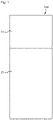
- FIG. 1 is a front view illustrating a refrigerator according to an embodiment of the present disclosure.
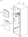
- FIG. 2 is an exploded perspective view illustrating a mounted state of each grill assembly of the refrigerator according to the embodiment of the present disclosure.
- FIG. 3 is a front view illustrating an internal state of the refrigerator according to the embodiment of the present disclosure.
- FIG. 4 is a cross-sectional view taken along line I-I on FIG. 3 .
- FIG. 5 is an enlarged view illustrating a portion indicated by a circle "A" on FIG. 4 .
- the refrigerator may be configured to include a cabinet 100, an evaporator 30, a freezing-compartment grill assembly 200, and a refrigerating-compartment grill assembly 300.
- a refrigerating-compartment discharge flow path 301 and a refrigerating-compartment retrieval path 302 are formed together in the refrigerating-compartment grill assembly 300.
- the refrigerator is configured to include the cabinet 100.
- the cabinet 100 may be configured to include an outer casing 110 and inner casings 121 and 122.
- the outer casing 110 provides an exterior appearance of the cabinet 100.
- the inner casings 121 and 122 are positioned inside the outer casing 110 and form a storage space.
- the inner casings 121 and 122 may be a freezing-compartment inner casing 121 and a refrigerating-compartment inner casing 122, respectively.
- the freezing-compartment inner casing 121 provides a freezing compartment 10.
- the refrigerating-compartment inner casing 122 provides a refrigerating compartment 20.
- the inner casings 121 and 122 are positioned in an upper space and a lower space, respectively, inside the outer casing 110 with a partition wall 130 in between.
- the freezing-compartment inner casing 121 is positioned over the partition wall 130 and provides the freezing compartment 10.
- the refrigerating-compartment inner casing 122 is positioned under the partition wall 130 and provides the refrigerating compartment 20.
- the respective positions of the freezing-compartment inner casing 121 and the refrigerating-compartment inner casing 122 are illustrated in FIGS. 3 to 5 .
- the partition wall 130 is formed in such a manner that an upper end portion thereof surrounds a lower end portion of the freezing-compartment inner casing 121.
- the partition wall 130 is formed in such a manner that a lower end portion thereof surrounds an upper end portion of the refrigerating-compartment inner casing 122.
- the partition wall 130 is formed as illustrated in FIG. 9 .
- the first transfer flow path 131 may be formed in the partition wall 130.
- the first transfer flow path 131 serves to be provided with cool air from the freezing-compartment grill assembly 200 and to supply the provided cool air to the refrigerating-compartment discharge flow path 301 in the refrigerating-compartment grill assembly 300.
- the first transfer flow path 131 may be formed in a rear side center portion of the partition wall 130 in a manner that passes through a rear side center portion from top to bottom.
- a front side branch flow path 132 is formed on a bottom end of the first transfer flow path 131.
- the front side branch flow path 132 extends from the bottom end thereof up to a front side bottom surface of the partition wall 130.
- the front side branch flow path 132 supplies the cool air to a front side space inside the refrigerating compartment 20.
- a rear side branch flow path 133 may further be formed on the bottom end of the first transfer flow path 131.
- the rear side branch flow path 133 supplies the cool air to the refrigerating-compartment discharge flow path 301 in the refrigerating-compartment grill assembly 300.
- the rear side branch flow path 133 may be formed in a manner that is gradually inclined downward from the first transfer flow path 131 toward the refrigerating-compartment discharge flow path 301.
- the first transfer flow path 131 and each of the branch flow paths 132 and 133 are formed as illustrated in FIGS. 5 to 7 .
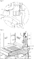
- FIG. 8 is a rear view illustrating the refrigerator according to the embodiment of the present disclosure from which the outer casing 110 is removed to describe a rear side structure of the inside of the refrigerator.
- FIG. 9 is a perspective view illustrating essential components of the refrigerator according to the embodiment of the present disclosure from which the outer casing 110 is removed to describe the rear side structure of the inside of the refrigerator.
- FIG. 10 is a perspective view illustrating essential components of the refrigerator according to the embodiment of the present disclosure from which a blocking cover is removed to describe a second transfer flow path 134 in a rear surface of the partition wall 130 in the rear side structure of the inside of the refrigerator.
- FIG. 11 is a rear view illustrating the essential components in FIG. 10 .
- the second transfer flow path 134 may be formed in the partition wall 130.
- the second transfer flow path 134 serves to be supplied with the cool air retrieved from the refrigerating-compartment grill assembly 300 and to guide flowing of the supplied cool air to a position where the evaporator 30 is positioned.
- the second transfer flow path 134 is formed in a rear surface of the partition wall 130 in a recessed manner, and a blocking cover 140 is provided on the rear surface of the partition wall 130.
- the blocking cover 140 covers the second transfer flow path 134 in such a manner as to be blocked from an outside environment.
- the blocking cover 140 may be detachably mounted on the rear surface of the partition wall 130.
- the second transfer flow path 134 is formed by the structure of the second transfer flow path recessed into the rear surface of the partition wall 130 and by the blocking cover 140.
- a structure for retrieving the cool air can be simplified.
- the second transfer flow path 134 is formed in such a manner that a cooling-air discharge side portion thereof is positioned on a rear side bottom of the evaporator 30.
- Communication groove 135 may be formed in opposite sides, respectively, of the second transfer flow path 134.
- the communication groove 135 communicates with a cool-air outlet of the refrigerating-compartment retrieval path 302.
- a guidance flow path 141 may be formed in the blocking cover 140.
- the cool air in the refrigerating-compartment retrieval path 302 is transferred to the guidance flow path 141 through the two communication grooves 135 in the second transfer flow path 134.
- the guidance flow path 141 guides flowing of the transferred cool air to above an upper center portion of the blocking cover 140.
- the freezing compartment 10 and the refrigerating compartment 20 are configured in such manner as to be opened and closed by doors 11 and 21, respectively.
- the doors 11 and 21 may be configured in such a manner as to employ a hinge mechanism.
- doors 11 and 21 may be configured as a drawer-type door.
- the refrigerator according to the embodiment of the present disclosure may be configured to include the evaporator 30.
- the evaporator 30 is configured in such a manner as to generate the cool air that is supplied to the freezing compartment 10 or the refrigerating compartment 20.
- the evaporator 30 constitutes a freezing system.
- the evaporator 30 exchanges heat with air flowing therethrough and thus performs a function of decreasing temperature of the air.
- the evaporator 30 may be positioned in a rear portion of the inside of the freezing compartment 10. Specifically, the evaporator 30 may be positioned adjacent to a front surface of a rear wall of the freezing compartment 10.
- the refrigerator may be configured to include the freezing-compartment grill assembly 200.
- the freezing-compartment grill assembly 200 serves to provide to the freezing compartment 10 and the refrigerating-compartment grill assembly 300 the cool air that exchanges heat with the evaporator 30 while passing therethrough.
- the freezing-compartment grill assembly 200 is positioned in front of the evaporator 30 inside the freezing compartment 10. That is, the freezing compartment 10 has a front side storage space and a rear side heat exchange space inside with the freezing-compartment grill assembly 200 in between.
- a blowing fan 201 that blows the cool air may be mounted in the freezing-compartment grill assembly 200.
- the blowing fan 201 may be configured as a module including both a fan and a motor. The blowing fan 201 supplies the cool air passing through the evaporator 30 to the freezing compartment 10 or the refrigerating compartment 20.
- a plurality of freezing-compartment discharge openings 202 is formed in the freezing-compartment grill assembly 200.
- a refrigerating-compartment discharge flow path 203 is formed in the freezing-compartment grill assembly 200.
- the refrigerating-compartment discharge flow path 203 guides discharging of the cool air blown by the blowing fan 201 to each of the freezing-compartment discharge openings 202.
- the refrigerating-compartment discharge flow path 203 may be formed in such a manner as to guide flowing of the cool air to above and below the opposite sides of a center portion of the freezing-compartment grill assembly 200 in which the blowing fan 201 is mounted.
- each of the freezing-compartment discharge openings 202 may be formed in the refrigerating-compartment discharge flow paths 203.
- a refrigerating-compartment supply flow path 204 is formed in the freezing-compartment grill assembly 200.
- the refrigerating-compartment supply flow path 204 is a flow path that is formed to supply one portion of the cool air blown by the blowing fan 201 to the refrigerating-compartment grill assembly 300.
- the refrigerating-compartment supply flow path 204 is formed in such a manner as to extend from the center portion of the freezing-compartment grill assembly 200, in which the blowing fan 201 is positioned, up to a bottom surface of the freezing-compartment grill assembly 200.
- a temperature adjustment device 206 (refer to FIGS. 3 and 4 ) may be provided in the refrigerating-compartment supply flow path 204.
- the temperature adjustment device 206 adjusts an amount of cool air passing therethrough and thus adjusts temperature inside the freezing compartment 10 or inside the refrigerating compartment 20.
- a freezing-compartment retrieval flow path 205 is formed in the freezing-compartment grill assembly 200.
- the freezing-compartment retrieval flow path 205 is formed in the bottom surface of the freezing-compartment grill assembly 200 in a recessed manner.
- the freezing-compartment retrieval flow path 205 is formed in such a manner that a front side end portion thereof is exposed to the inside of the freezing compartment 10 and that a rear side end portion thereof is exposed to a bottom of the evaporator 30.
- the cool water flowing through the inside of the freezing compartment 10 is retrieved toward the cool-air inflow side of the evaporator 30 through the freezing-compartment retrieval flow path 205.
- the refrigerator may be configured to include the refrigerating-compartment grill assembly 300.
- the refrigerating-compartment grill assembly 300 is configured in such a manner to guide discharging of the cool air transferred from the freezing-compartment grill assembly 200 into the refrigerating compartment 20.
- the refrigerating-compartment grill assembly 300 is positioned in a rear portion of the inside of the refrigerating compartment 20. Specifically, the refrigerating-compartment grill assembly 300 is positioned in front of a front surface of a rear wall of the refrigerating-compartment inner casing 122.
- the refrigerating-compartment discharge flow path 301 and the refrigerating-compartment retrieval path 302 are formed together in the refrigerating-compartment grill assembly 300.
- the cool air flows to the refrigerating-compartment discharge flow path 301 from the freezing-compartment grill assembly 200.
- the refrigerating-compartment discharge flow path 301 serves to guide discharging of the cool air into the refrigerating compartment 20.
- the refrigerating-compartment retrieval path 302 serves to guide flowing of the cool retrieved from the refrigerating compartment 20 into the freezing compartment 10.
- FIG. 12 is an exploded perspective view illustrating the refrigerating-compartment grill assembly 300 of the refrigerator according to the embodiment of the present disclosure.
- FIG. 13 is a perspective view illustrating an assembled state of the refrigerating-compartment grill assembly 300 of the refrigerator according to the embodiment of the present disclosure.
- FIG. 14 is a perspective view illustrating a state where a first duct unit and a second duct unit of the refrigerating-compartment grill assembly 300 are combined with each other in the rear of the refrigerator according to the embodiment of the present disclosure.
- FIG. 15 is a perspective view illustrating a state where a blocking plate is mounted on the refrigerating-compartment grill assembly 300 of the refrigerator according to the embodiment of the present disclosure.
- the refrigerating-compartment grill assembly 300 is configured to include a first duct unit 310.
- the first duct unit 310 provides a front surface of the refrigerating-compartment grill assembly 300 and is positioned in a manner that is exposed to the inside of the refrigerating compartment 20.
- the first duct unit 310 is formed in a manner that has a greater width in the leftward-rightward direction than the second duct unit 320 described below.
- surrounding walls are formed on an edge of the first duct unit 310. That is, the first duct unit 310 is formed in such a manner as to have an upper wall 311 and lateral walls 312 on opposite sides thereof.
- the upper wall 311 provides an upper surface of the first duct unit 310
- the lateral walls 312 provide opposite lateral surfaces thereof, respectively.
- the surrounding walls (the upper wall 311 and the lateral walls 312) of the first duct unit 310 may be formed in such a manner that respective heights in the forward-backward direction thereof are such that the cool air can flow. That is, thicknesses (heights) in the forward-backward direction of the first duct unit 310 are minimized so that a space inside the refrigerating compartment 20 can be maximally secured.
- a plurality of refrigerating-compartment discharge openings 310a may be formed in the first duct unit 310.
- the refrigerating-compartment discharge openings 310a are formed according to the height direction of the first duct unit 310.
- the cool air is discharged into spaces of different heights inside the refrigerating compartment 20.
- each of the spaces of different heights may be a space between shelves provided inside the refrigerating compartment 20.
- the refrigerating-compartment discharge openings 310a are formed in opposite sides, respectively, of the first duct unit 310. Therefore, the cool air may be uniformly supplied into opposite side spaces inside the refrigerating compartment 20
- the refrigerating-compartment grill assembly 300 is configured to include the second duct unit 320.
- the second duct unit 320 is provided to a portion of the refrigerating-compartment grill assembly 300 in which the refrigerating-compartment discharge flow path 301 is formed.
- a front surface of the second duct unit 320 is brought into close contact with one portion of a rear surface of the first duct unit 310 for being combined therewith.
- the front surface of the second duct unit 320 may be brought into close contact with a center portion of the rear surface of the first duct unit 310.
- the second duct unit 320 is formed in a manner that has a smaller width in the leftward-rightward direction than the first duct unit 310.
- the refrigerating-compartment retrieval path 302 is formed between one lateral wall of the first duct unit 310 and one lateral wall of the second duct unit 320 and between the other lateral wall of the first duct unit 310 and the other lateral wall of the second duct unit 320.
- a space between one lateral wall of the first duct unit 310 and one lateral wall of the second duct unit 320 and a space between the other lateral wall of the first duct unit 310 and the other lateral wall of the second duct unit 320 are used as the refrigerating-compartment retrieval paths 302, respectively.
- the first duct unit 310 is formed in a manner that is open at the bottom.
- Retrieval cool-air inlets 313a are formed opposite sides, respectively, of a bottom surface between the first duct unit 310 and the second duct unit 320.
- the retrieval cool-air inlets 313a communicate with the refrigerating-compartment retrieval paths 302, respectively.
- Retrieval cool-air outlets 311b are formed in opposite sides, respectively, of the upper wall 311 of the first duct unit 310.
- the retrieval cool-air outlets 311b communicate with the refrigerating-compartment retrieval flow paths 302, respectively. That is, the cool air that flows through the refrigerating compartment 20 flows into the refrigerating-compartment retrieval path 302 through the retrieval cool-air inlet 313a and then is discharged through the retrieval cool-air outlet 311b.
- the retrieval cool-air outlets 311b communicate with the communication grooves 135, respectively, that are formed in the opposite sides of the second transfer flow path 134. Accordingly, the cool air that flows along the refrigerating-compartment retrieval path 302 passes sequentially through the retrieval cool-air outlet 311b and the communication groove 135 and then is retrieved toward the cool-air inflow side of the evaporator 30 along the guidance flow path 141 formed in the blocking cover 140.
- a supply cool-air inlet 311a is formed in the upper wall 311 of the first duct unit 310.
- the supply cool-air inlet 311a serves to supply the cool air to the refrigerating-compartment discharge flow path 301.
- the supply cool-air inlet 311a is formed in a center portion of the upper wall 311 of the first duct unit 310.
- the retrieval cool-air outlets 311b may be formed to opposite sides, respectively, of the supply cool-air inlet 311a, and are positioned in such a manner as to correspond to the communication grooves 135, respectively, formed in the above-described partition wall 130.
- a communication discharge opening 320a is formed in the second duct unit 320 in a manner that communicates with each of the refrigerating-compartment discharge openings 310a in the first duct unit 310 and thus discharges the cool air.
- the communication discharge openings 320a may be formed at positions, respectively, that correspond to positions of the refrigerating-compartment discharge openings 310a. That is, since the refrigerating-compartment discharge openings 310a are formed in opposite sides, respectively, of the first duct unit 310, the communication discharge openings 320a may be formed in opposite sides, respectively, of the second duct unit 320.
- the refrigerating-compartment discharge flow path 301 is formed in a rear surface of the second duct unit 320 in a recessed manner. Specifically, a cool-air inlet of the refrigerating-compartment discharge flow path 301 may be formed at a position that corresponds to a position of the supply cool-air inlet 311a in the first duct unit 310. In this case, the supply cool-air inlet 311a is positioned in such a manner as to correspond to a lower end of the rear side branch flow path 133 branching off from the first transfer flow path 131 in the partition wall 130.
- the refrigerating-compartment discharge flow path 301 may be formed in such a manner to pass through each of the communication discharge openings 320a.
- the refrigerating-compartment discharge flow paths 301 are formed in such a manner as to branch off from the cool-air inlet into opposite sides, respectively, of the second duct unit 320, to pass through the communication discharge openings 320a, respectively, and to reach bottoms, respectively, of the opposite sides of the second duct unit 320.
- An upper surface of the second duct unit 320 is brought into close contact with a bottom surface of the upper wall 311 of the first duct unit 310.
- a bottom surface of the second duct unit 320 is brought into close contact with an upper surface of a lower wall 313 of the first duct unit 310.
- the refrigerating-compartment grill assembly 300 may be configured to include a blocking plate 330.
- the blocking plate 330 is formed in such a manner as to cover both rear surfaces of the first duct unit 310 and the second duct unit 320. That is, with the blocking plate 330, the refrigerating-compartment discharge flow path 301 and the two refrigerating-compartment retrieval paths 302 may be formed as paths blocked from the external environment.
- the blocking plate 330 is formed of an insulating material. Accordingly, the cool air that flows along the refrigerating-compartment discharge flow path 301 or the refrigerating-compartment retrieval path 302 can be prevented from being affected by outside air.
- the compressor (not illustrated) and the blowing fan 201 operate.
- the compressor operates with a cooling cycle according to a condition of temperature inside the freezing compartment 10 or the refrigerating compartment 20.
- the compressor when the temperature inside the freezing compartment 10 or the refrigerating compartment 20 reaches a range of improper temperatures (a range of temperatures higher than a setting temperature), the compressor operates, and thus refrigerant flows sequentially through the condenser, the expander, and the evaporator 30.
- the blowing fan 201 operates, and thus the cool air that exchanges heat with the evaporator 30 while passing therethrough is supplied to the freezing compartment 10 and the refrigerating compartment 20 through the grill assembly 200.
- the cool air that is retrieved from the freezing compartment 10 or the refrigerating compartment 20 by the operation of the blowing fan 201 passes through the evaporator 30. Moisture is removed from the cool air passing through the evaporator 30. As a result of the heat exchange, temperature of the cool air is decreased to a lower temperature.
- the cool air passing through the evaporator 30 passes through the blowing fan 201 and then flows into the freezing-compartment grill assembly 200. Subsequently, while flowing along the refrigerating-compartment discharge flow path 203 formed in the freezing-compartment grill assembly 200, the cool air is supplied into the freezing compartment 10 through each of the freezing-compartment discharge openings 202 formed in the freezing-compartment grill assembly 200.
- an object subject to being stored in a frozen state is frozen by the cool air in the freezing compartment 10 for being stored.
- Cool air circulation for freezing is as illustrated in FIG. 16 .
- One portion of the cool air flowing into the freezing-compartment grill assembly 200 flows along the refrigerating-compartment supply flow path 204 formed in the freezing-compartment grill assembly 200 and then is provided to the first transfer flow path 131 formed in the partition wall 130.
- the cool air provided to the first transfer flow path 131 flows along the first transfer flow path 131, and then the cool air branches off into two streams.
- the two streams of the cool air flow along the front side branch flow path 132 and the rear side branch flow path 133, respectively, that extend from the bottom end of the first transfer flow path 131.
- the cool air that flows along the front side branch flow path 132 passes through the front side bottom surface of the partition wall 130 and is supplied into the front side space inside the refrigerating compartment 20.
- the cool air flowing along the rear side branch flow path 133 passes through the supply cool-air inlet 311a formed in the first duct unit 310 of the refrigerating-compartment grill assembly 300 and is supplied to the refrigerating-compartment discharge flow path 301 formed in the second duct unit 320.
- the cool air While flowing along the first duct unit 310, the cool air is discharged sequentially through each of the communication discharge openings 320a formed in the second duct unit 320 and each of the refrigerating-compartment discharge openings 310a formed in the refrigerating-compartment discharge flow path 301 and is supplied into each of the spaces of different heights inside the refrigerating compartment 20.
- Cool air circulation for refrigerating is as illustrated in FIG. 17 .
- the cool air supplied into the refrigerating compartment 20 circulates through the inside of the refrigerating compartment 20 and then flows into the retrieval cool-air inlets 313a formed in opposite sides of the lower wall 313 of the first duct unit 310 constituting the refrigerating-compartment grill assembly 300.
- the cool air flows along the refrigerating-compartment retrieval path 302 communicating with the retrieval cool-air inlet 313a. Then, the cool air passes sequentially through the retrieval cool-air outlets 311b formed in opposite sides respectively, of the upper wall 311 of the first duct unit 310 and through the communication grooves 135 positioned in such a manner as to correspond to the retrieval coo-air outlets 311b, respectively. Then, the cool air is provided to the second transfer flow path 134. Cool air circulation is as illustrated in FIGS. 18 and 19 .
- the cool air is retrieved toward the cool-air inflow side of the evaporator 30 along the guidance flow path 141 in the blocking cover 140 formed in such a manner as to cover the second transfer flow path 134. Then, the cool air passes back through the evaporator 30. This cool air circulation for heat exchange is repeated.
- the blowing fan 201 and the compressor stops operating.
- the blowing fan 201 and the compressor may be controlled in such a manner as to stop operating.
- the refrigerating-compartment discharge flow path 301 for supplying the cool air to the refrigerating compartment 20 and the refrigerating-compartment retrieval path 302 for retrieving the cool air circulating through the refrigerating compartment 20 are formed together in the refrigerating-compartment grill assembly 300. Accordingly, an overall structure of the refrigerator according to the present disclosure may be simplified because there is no need to provide a separate duct for retrieving the cool air.
- a cool-air inlet of the refrigerating-compartment retrieval path 302 for retrieving the cool air inside the refrigerating compartment 20 is formed in a bottom surface of the refrigerating-compartment grill assembly 300. Accordingly, the cool air supplied into an upper space inside the refrigerating compartment 20 sufficiently flows through the inside of the refrigerating compartment 20 and then is discharged. Thus, the efficiency of refrigerating can be improved.
- the refrigerator according to the present disclosure is configured in such a manner that the cool air retrieved through the refrigerating-compartment retrieval path 302 in the refrigerating-compartment grill assembly 300 is transferred to the evaporator 30 through the second transfer flow path 134 formed in a rear surface of the partition wall 130. With this configuration, insulation loss can be reduced.
Abstract
Proposed is a refrigerator including a cabinet having a freezing compartment above a partition wall and a refrigerating compartment there below, an evaporator positioned behind the freezing compartment and generating cool air, a freezing-compartment grill assembly positioned in front of the evaporator inside the freezing compartment, a blowing fan for blowing the cool air being mounted in the freezing-compartment grill assembly, and a refrigerating-compartment grill assembly positioned behind the refrigerating compartment, wherein a refrigerating-compartment discharge flow path guiding discharging of the cool air supplied from the freezing-compartment grill assembly into the refrigerating compartment, and a refrigerating-compartment retrieval flow path guiding flowing of the cool air retrieved from the refrigerating compartment into the freezing compartment are formed together in the refrigerating-compartment grill assembly.
Description
- The present application claims priority to
Korean Patent Application No. 10-2021-0002287, filed 08, JANUARY 2021 - The present disclosure relates to a refrigerator including a grill assembly in which a discharge flow path and an absorption flow path for supplying and retrieving cool air into a storage compartment are provided together.
- Usually, refrigerators are a household appliance that is configured to store various foodstuffs and drinks for a long period of time using cool air that is generated by circulating refrigerant with a freezing cycle.
- Refrigerators are categorized into top freezer type refrigerators in which a freezing compartment is arranged over a refrigerating compartment, bottom freezer type refrigerators in which the freezing compartment is arranged under the refrigerating compartment, and side-by-side type refrigerators in which the refrigerating compartment and the freezing compartment are arranged side by side in the leftward-rightward direction.
- In the top freezer type refrigerators, an evaporator is positioned in a rear side space inside the freezing compartment, and a freezing-compartment grill assembly in which a blowing fan for supplying and circulating cool air toward the freezing compartment is mounted is positioned in front of the evaporator.
- In addition, in the top freezer type refrigerators, a refrigerating-compartment grill assembly is positioned in a rear side space inside the refrigerating compartment.
- One portion of the cool air, supplied by the freezing-compartment grill assembly, is supplied to the refrigerating-compartment grill assembly through a connection flow path. The cool air supplied through the connection flow path is supplied into the refrigerating compartment.
- The top freezer type refrigerators are as disclosed in
Korean Patent No. 10-0160419 10-1999-0060433 10-2016-0100548 10-2017-0006995 - The above-described top freezer type refrigerators in the related art are configured in such a manner that a retrieval flow path is formed in a partition wall by which division into the freezing compartment and the refrigerating compartment is realized and that the cool air circulating through the inside of the refrigerating compartment is retrieved into the evaporator behind the freezing compartment.
- Accordingly, in the top freezer type refrigerators in the related art, the cool air discharged from an upper portion of the refrigerating-compartment grill assembly is discharged directly to the retrieval flow path without being sufficiently supplied all the way up to the front side of the refrigerating compartment that has the same height as the upper portion. Due to this phenomenon, the efficiency of refrigerating is decreased.
- Particularly, the above-described retrieval flow path makes it very difficult to form another flow path in the partition wall. For this reason, various design changes do not have been made using the partition wall. That is, selection of the retrieval flow path is limited when forming a new flow path in the partition wall.
- In addition, the partition wall needs to provide sufficient thermal insulation in order to maintain predetermined temperatures inside the freezing compartment and the refrigerating compartment. However, the insulation performance of the partition is decreased due to the above-described retrieval flow path.
- The foregoing is intended merely to aid in the understanding of the background of the present disclosure, and is not intended to mean that the present disclosure falls within the purview of the related art that is already known to those skilled in the art.
- Document of Related Art:
- (Patent Document 1)
Korean Patent No. 10-0160419 - (Patent Document 2)
Korean Patent Application Publication No. 10-1999-0060433 - (Patent Document 3)
Korean Patent Application Publication No. 10-2016-0100548 - (Patent Document 4)
Korean Patent Application Publication No. 10-2017-0006995 - An objective of the present disclosure is to provide a refrigerator including a refrigerating-compartment grill assembly in which a refrigerating-compartment discharge flow path for supplying cool air to a refrigerating compartment and a freezing-compartment retrieval flow path for retrieving the cool air circulating through a freezing compartment are provided together.
- Another objective of the present disclosure is to provide a refrigerator including a new type of refrigerating-compartment grill assembly capable of causing cool air supplied into an upper space inside a refrigerating compartment to flow sufficiently through the inside of the refrigerating compartment and then discharging the cool air, thereby increasing the efficiency of refrigerating.
- Still another objective of the present disclosure is to provide a refrigerator including a new type of refrigerating-compartment grill assembly in which a refrigerating-compartment retrieval flow path is formed in a partition wall by which division into a refrigerating compartment and a freezing compartment is realized, thereby preventing the occurrence of insulation loss caused in the related art.
- The object is solved by the features of the independent claims. Preferred embodiments are given in the dependent claims.
- According to an aspect of the present disclosure, there is a refrigerator in which a flow path for discharging cool air to a refrigerating compartment and a flow path for discharging the cool air to a freezing compartment are formed together in a refrigerating-compartment grill assembly.
- The following optional features could be combined alone or in combination with the above mentioned most abstract version of the refrigerator.
- In one or more embodiments, a flow path guiding discharging of the cool air supplied from a freezing-compartment grill assembly into the refrigerating compartment may be formed in a refrigerating-compartment grill assembly.
- In one or more embodiments, a refrigerating-compartment retrieval flow path guiding flowing of the cool air retrieved from the refrigerating compartment into the freezing compartment may be formed in the freezing-compartment grill assembly.
- In one or more embodiments, a flow path may be formed in a partition wall.
- In one or more embodiments, the flow path formed in the partition wall may include a flow path that is provided with the cool air from the freezing-compartment grill assembly.
- In one or more embodiments, the flow path may supply the provided cool air to a refrigerating-compartment discharge flow path in the refrigerating-compartment grill assembly.
- In one or more embodiments, the flow path formed in the partition wall may include a first transfer flow path that passes through a rear side center portion of the partition wall from top to bottom.
- In one or more embodiments, a cool-air inlet of the refrigerating-compartment discharge flow path may be positioned more downward in a backward direction than a bottom end of the first transfer flow path.
- In one or more embodiments, a rear side branch flow path connected to the refrigerating-compartment discharge flow path and a front side branch flow path extending up to a front side bottom surface of the partition wall may be both formed on the bottom end of the first transfer flow path.
- In one or more embodiments, the rear side branch flow path may be formed in a manner that is gradually inclined downward from the first transfer flow path toward the refrigerating-compartment discharge flow path.
- In one or more embodiments, a second transfer flow path that is provided with the cool air from the refrigerating-compartment retrieval flow path in the refrigerating-compartment grill assembly and guides flowing of the provided cool air to a position where an evaporator is positioned may be formed in the partition wall.
- In one or more embodiments, the second transfer flow path may be formed in a rear surface of the partition wall in a recessed manner.
- In one or more embodiments, a blocking covering the second transfer flow path in such a manner as to be blocked from an external environment may be provided on the rear surface of the partition wall.
- In one or more embodiments, the blocking cover may be detachably mounted on the rear surface of the partition wall.
- In one or more embodiments, a cool-air outlet of the refrigerating-compartment retrieval flow path may be formed in each of the opposite sides of an upper surface of the refrigerating-compartment grill assembly.
- In one or more embodiments, a communication groove may be formed in each of the opposite sides of the second transfer flow path in a manner that passes through each of the opposite sides thereof and reaches a position where the cool-air outlet is positioned.
- In one or more embodiments, a guidance flow path guiding flowing of the cool air in the refrigerating-compartment retrieval flow path transferred through the two communication grooves in the second transfer flow path to above an upper center portion of the blocking cover may be formed in the blocking cover.
- In one or more embodiments, the refrigerating-compartment grill assembly may include a first duct unit and a second duct unit.
- In one or more embodiments, the first duct unit may be formed to be positioned in a manner that is exposed to the inside of the refrigerating compartment.
- In one or more embodiments, the first duct unit may have a plurality of refrigerating-compartment discharge openings.
- In one or more embodiments, the refrigerating-chamber discharge flow path may be formed in the second duct unit.
- In one or more embodiments, the first duct unit may be formed in such a manner as to have a greater width in a leftward-rightward direction than the second duct unit.
- In one or more embodiments, the first duct unit may have lateral walls on opposite sides thereof.
- In one or more embodiments, a front surface of the second duct unit may be brought into close contact with one portion of the rear surface of the first duct unit.
- In one or more embodiments, rear surfaces of the first duct unit and the second duct unit may be covered by a blocking plate.
- In one or more embodiments, the refrigerating-compartment discharge flow path may be formed in the rear surface of the second duct unit in a recessed manner.
- In one or more embodiments, the refrigerating-compartment discharge flow path may be formed as a path that is blocked by the blocking plate from an outside environment.
- In one or more embodiments, the blocking plate may be formed of an insulating material.
- In one or more embodiments, the second duct unit may be positioned in a center portion of the rear surface of the first duct unit.
- In one or more embodiments, the refrigerating-compartment retrieval flow path may be formed between one lateral wall of the first duct unit and one lateral wall of the second duct unit and between the other lateral wall of the first duct unit and the other lateral wall of the second duct unit.
- In one or more embodiments, a communication discharge opening may be formed in the second duct unit in a manner that communicates with each of the refrigerating-compartment discharge openings in the first duct unit and thus discharges the cool air.
- In one or more embodiments, the refrigerating-compartment discharge flow path may be formed in such a manner as to pass through each of the communication discharge openings.
- In one or more embodiments, the refrigerating-compartment discharge openings may be formed in opposite sides, respectively, of the first duct unit.
- In one or more embodiments, the communication discharge openings may be formed in portions, respectively, of the first duct unit that correspond to the refrigerating-compartment discharge openings when the second duct unit is combined with the rear surface of the first duct unit.
- In one or more embodiments, the refrigerating-compartment discharge flow paths may be formed in such a manner as to branch off from a cool-air inlet into opposite sides, respectively, of the second duct unit, to pass through the communication discharge openings, respectively, and to reach bottoms, respectively, of the opposite sides of the second duct unit.
- In one or more embodiments, the cool-air inlet of the refrigerating-component discharge flow path may be formed in a center portion of an upper surface of the second duct unit in a manner that passes therethrough.
- In one or more embodiments, the first duct unit may be formed in such a manner as to be open at opposite sides bottom surfaces and opposite sides upper surfaces, and the cool air inside the refrigerating compartment may flow into each of the refrigerating-compartment retrieval flow paths through openings in the opposite sides bottom surfaces and then may be discharged through openings in the opposite side upper surfaces.
- As described above, in the refrigerator according to the present disclosure, the discharge flow path for supplying the cool air to the refrigerating compartment and the refrigerating-compartment retrieval flow path for retrieving the cool air circulating through the refrigerating compartment are formed together in the refrigerating-compartment grill assembly. Thus, the effect of simplifying an overall structure of the refrigerator without the need to provide a separate duct for retrieving the cool air can be achieved.
- In the refrigerator according to the present disclosure, the cool-air inlet of the refrigerating-compartment retrieval flow path for retrieving the cool air inside the refrigerating compartment is formed in a bottom surface of the refrigerating-compartment grill assembly. Thus, the cool air supplied into an upper space inside the refrigerating compartment can flow sufficiently through the inside of the refrigerating compartment and then can be discharged. Thus, the effect of improving the efficiency of refrigerating can be achieved.
- The refrigerator according to the present disclosure is configured in such a manner that the cool air retrieved through the refrigerating-compartment retrieval flow path in the refrigerating-compartment grill assembly is transferred to the evaporator through the second transfer flow path formed in the rear surface of the partition wall without passing through the inside of the partition wall. Thus, the effect of reducing insulation loss can be achieved.
- The above and other objectives, features, and other advantages of the present disclosure will be more clearly understood from the following detailed description when taken in conjunction with the accompanying drawings, in which:
-
FIG. 1 is a front view illustrating a refrigerator of an embodiment of the present disclosure; -
FIG. 2 is an exploded perspective view illustrating a mounted state of each grill assembly of the refrigerator according to the embodiment of the present disclosure; -
FIG. 3 is a front view of an internal state of the refrigerator of the embodiment of the disclosure; -
FIG. 4 is a cross-sectional view taken along line I-I onFIG. 3 ; -
FIG. 5 is an enlarged view illustrating a portion indicated by a circle "A" onFIG. 4 ; -
FIGS. 6 and7 are cross-sectional views each illustrating essential components, respectively, that are differently cross-sectioned to describe an internal structure of a partition wall of the refrigerator according to the embodiment of the present disclosure; -
FIG. 8 is a rear view illustrating the refrigerator of the embodiment of the present disclosure from which an outer casing is removed to describe a rear side structure of the inside of the refrigerator; -
FIG. 9 is a perspective view illustrating essential components of the refrigerator according to the embodiment of the present disclosure from which the outer casing is removed to describe the rear side structure of the inside of the refrigerator; -
FIG. 10 is a perspective view illustrating essential components of the refrigerator of the embodiment of the disclosure from which a block cover is removed to describe a second transfer flow path in a rear surface of the partition wall in the rear side structure of the inside of the refrigerator; -
FIG. 11 is a rear view illustrating the essential components inFIG. 10 ; -
FIG. 12 is an exploded perspective view illustrating a refrigerating-compartment grill assembly of the refrigerator according to the embodiment of the present disclosure; -
FIG. 13 is a perspective view illustrating an assembled state of the refrigerating-compartment grill assembly of the refrigerator according to the embodiment of the present disclosure; -
FIG. 14 is a perspective view illustrating a state where a first duct unit and a second duct unit of the refrigerating-compartment grill assembly are combined with each other in the rear of the refrigerator according to the embodiment of the present disclosure; -
FIG. 15 is a perspective view illustrating a state where a blocking plate is mounted on the refrigerating-compartment grill assembly of the refrigerator of the embodiment of the present disclosure; -
FIG. 16 is a cross-sectional view illustrating a state where cool air circulates through a freezing compartment of the refrigerator according to the present disclosure; -
FIG. 17 is a cross-sectional view illustrating a state where the cool air circulates through a refrigerating compartment of the refrigerator according to the present disclosure; -
FIG. 18 is a perspective view illustrating a state where the cool air circulates through the refrigerating-compartment grill assembly of the refrigerator according to the present disclosure; and -
FIG. 19 is a cross-sectional view illustrating essential components that are cross-sectioned to describe a state where the cool air circulates through the inside of the refrigerating-compartment grill assembly of the refrigerator according to the present disclosure. - A preferred embodiment of the present disclosure will be described below with reference to
FIGS. 1 to 19 . -
FIG. 1 is a front view illustrating a refrigerator according to an embodiment of the present disclosure.FIG. 2 is an exploded perspective view illustrating a mounted state of each grill assembly of the refrigerator according to the embodiment of the present disclosure.FIG. 3 is a front view illustrating an internal state of the refrigerator according to the embodiment of the present disclosure.FIG. 4 is a cross-sectional view taken along line I-I onFIG. 3 .FIG. 5 is an enlarged view illustrating a portion indicated by a circle "A" onFIG. 4 . - As illustrated in
FIGS. 1 to 5 , the refrigerator according to the embodiment of the present disclosure may be configured to include acabinet 100, anevaporator 30, a freezing-compartment grill assembly 200, and a refrigerating-compartment grill assembly 300. Particularly, a refrigerating-compartmentdischarge flow path 301 and a refrigerating-compartment retrieval path 302 are formed together in the refrigerating-compartment grill assembly 300. - Components of the refrigerator according to the embodiment of the present disclosure will be described below.
- First, the refrigerator according to the embodiment of the present disclosure is configured to include the
cabinet 100. - The
cabinet 100 may be configured to include anouter casing 110 andinner casings outer casing 110 provides an exterior appearance of thecabinet 100. Theinner casings outer casing 110 and form a storage space. - In this case, the
inner casings inner casing 121 and a refrigerating-compartmentinner casing 122, respectively. The freezing-compartmentinner casing 121 provides a freezing compartment 10. The refrigerating-compartmentinner casing 122 provides arefrigerating compartment 20. - The
inner casings outer casing 110 with apartition wall 130 in between. - That is, the freezing-compartment
inner casing 121 is positioned over thepartition wall 130 and provides the freezing compartment 10. The refrigerating-compartmentinner casing 122 is positioned under thepartition wall 130 and provides therefrigerating compartment 20. The respective positions of the freezing-compartmentinner casing 121 and the refrigerating-compartmentinner casing 122 are illustrated inFIGS. 3 to 5 . - More specifically, the
partition wall 130 is formed in such a manner that an upper end portion thereof surrounds a lower end portion of the freezing-compartmentinner casing 121. Thepartition wall 130 is formed in such a manner that a lower end portion thereof surrounds an upper end portion of the refrigerating-compartmentinner casing 122. Thepartition wall 130 is formed as illustrated inFIG. 9 . - The first
transfer flow path 131 may be formed in thepartition wall 130. The firsttransfer flow path 131 serves to be provided with cool air from the freezing-compartment grill assembly 200 and to supply the provided cool air to the refrigerating-compartmentdischarge flow path 301 in the refrigerating-compartment grill assembly 300. - The first
transfer flow path 131 may be formed in a rear side center portion of thepartition wall 130 in a manner that passes through a rear side center portion from top to bottom. In this case, a front sidebranch flow path 132 is formed on a bottom end of the firsttransfer flow path 131. The front sidebranch flow path 132 extends from the bottom end thereof up to a front side bottom surface of thepartition wall 130. The front sidebranch flow path 132 supplies the cool air to a front side space inside the refrigeratingcompartment 20. - A rear side
branch flow path 133 may further be formed on the bottom end of the firsttransfer flow path 131. The rear sidebranch flow path 133 supplies the cool air to the refrigerating-compartmentdischarge flow path 301 in the refrigerating-compartment grill assembly 300. The rear sidebranch flow path 133 may be formed in a manner that is gradually inclined downward from the firsttransfer flow path 131 toward the refrigerating-compartmentdischarge flow path 301. - The first
transfer flow path 131 and each of thebranch flow paths FIGS. 5 to 7 . -
FIG. 8 is a rear view illustrating the refrigerator according to the embodiment of the present disclosure from which theouter casing 110 is removed to describe a rear side structure of the inside of the refrigerator.FIG. 9 is a perspective view illustrating essential components of the refrigerator according to the embodiment of the present disclosure from which theouter casing 110 is removed to describe the rear side structure of the inside of the refrigerator.FIG. 10 is a perspective view illustrating essential components of the refrigerator according to the embodiment of the present disclosure from which a blocking cover is removed to describe a secondtransfer flow path 134 in a rear surface of thepartition wall 130 in the rear side structure of the inside of the refrigerator.FIG. 11 is a rear view illustrating the essential components inFIG. 10 . - As illustrated in
FIGS. 8 to 11 , the secondtransfer flow path 134 may be formed in thepartition wall 130. The secondtransfer flow path 134 serves to be supplied with the cool air retrieved from the refrigerating-compartment grill assembly 300 and to guide flowing of the supplied cool air to a position where theevaporator 30 is positioned. - Particularly, the second
transfer flow path 134 is formed in a rear surface of thepartition wall 130 in a recessed manner, and a blockingcover 140 is provided on the rear surface of thepartition wall 130. The blockingcover 140 covers the secondtransfer flow path 134 in such a manner as to be blocked from an outside environment. In this case, the blockingcover 140 may be detachably mounted on the rear surface of thepartition wall 130. - That is, instead of providing a separate duct for transferring the cool air retrieved from the refrigerating compartment 22 to the
evaporator 30, the secondtransfer flow path 134 is formed by the structure of the second transfer flow path recessed into the rear surface of thepartition wall 130 and by the blockingcover 140. Thus, a structure for retrieving the cool air can be simplified. - In this case, the second
transfer flow path 134 is formed in such a manner that a cooling-air discharge side portion thereof is positioned on a rear side bottom of theevaporator 30. -
Communication groove 135 may be formed in opposite sides, respectively, of the secondtransfer flow path 134. Thecommunication groove 135 communicates with a cool-air outlet of the refrigerating-compartment retrieval path 302. - Moreover, a
guidance flow path 141 may be formed in the blockingcover 140. The cool air in the refrigerating-compartment retrieval path 302 is transferred to theguidance flow path 141 through the twocommunication grooves 135 in the secondtransfer flow path 134. Theguidance flow path 141 guides flowing of the transferred cool air to above an upper center portion of the blockingcover 140. - In addition, the freezing compartment 10 and the
refrigerating compartment 20 are configured in such manner as to be opened and closed bydoors doors - Of course, although not illustrated, the
doors - Next, the refrigerator according to the embodiment of the present disclosure may be configured to include the
evaporator 30. - The
evaporator 30 is configured in such a manner as to generate the cool air that is supplied to the freezing compartment 10 or therefrigerating compartment 20. - Particularly, along with a compressor 60 (refer to
FIG. 4 ), a condenser (not illustrated), and an expander (not illustrated), theevaporator 30 constitutes a freezing system. Theevaporator 30 exchanges heat with air flowing therethrough and thus performs a function of decreasing temperature of the air. - The
evaporator 30 may be positioned in a rear portion of the inside of the freezing compartment 10. Specifically, theevaporator 30 may be positioned adjacent to a front surface of a rear wall of the freezing compartment 10. - Next, the refrigerator according to the embodiment of the present disclosure may be configured to include the freezing-
compartment grill assembly 200. - The freezing-
compartment grill assembly 200 serves to provide to the freezing compartment 10 and the refrigerating-compartment grill assembly 300 the cool air that exchanges heat with theevaporator 30 while passing therethrough. - As illustrated in
FIG. 4 , the freezing-compartment grill assembly 200 is positioned in front of theevaporator 30 inside the freezing compartment 10. That is, the freezing compartment 10 has a front side storage space and a rear side heat exchange space inside with the freezing-compartment grill assembly 200 in between. - Moreover, a blowing
fan 201 that blows the cool air may be mounted in the freezing-compartment grill assembly 200. In this case, the blowingfan 201 may be configured as a module including both a fan and a motor. The blowingfan 201 supplies the cool air passing through theevaporator 30 to the freezing compartment 10 or therefrigerating compartment 20. - As illustrated in
FIG. 3 , a plurality of freezing-compartment discharge openings 202 (refer toFIG. 3 ) is formed in the freezing-compartment grill assembly 200. - Moreover, as illustrated in
FIG. 3 , a refrigerating-compartmentdischarge flow path 203 is formed in the freezing-compartment grill assembly 200. The refrigerating-compartmentdischarge flow path 203 guides discharging of the cool air blown by the blowingfan 201 to each of the freezing-compartment discharge openings 202. In this case, the refrigerating-compartmentdischarge flow path 203 may be formed in such a manner as to guide flowing of the cool air to above and below the opposite sides of a center portion of the freezing-compartment grill assembly 200 in which the blowingfan 201 is mounted. In this case, each of the freezing-compartment discharge openings 202 may be formed in the refrigerating-compartmentdischarge flow paths 203. - In addition, as illustrated in
FIG. 3 , a refrigerating-compartmentsupply flow path 204 is formed in the freezing-compartment grill assembly 200. - The refrigerating-compartment
supply flow path 204 is a flow path that is formed to supply one portion of the cool air blown by the blowingfan 201 to the refrigerating-compartment grill assembly 300. The refrigerating-compartmentsupply flow path 204 is formed in such a manner as to extend from the center portion of the freezing-compartment grill assembly 200, in which the blowingfan 201 is positioned, up to a bottom surface of the freezing-compartment grill assembly 200. - Although not specifically illustrated, a temperature adjustment device 206 (refer to
FIGS. 3 and4 ) may be provided in the refrigerating-compartmentsupply flow path 204. Thetemperature adjustment device 206 adjusts an amount of cool air passing therethrough and thus adjusts temperature inside the freezing compartment 10 or inside the refrigeratingcompartment 20. - In addition, a freezing-compartment
retrieval flow path 205 is formed in the freezing-compartment grill assembly 200. The freezing-compartmentretrieval flow path 205 is formed in the bottom surface of the freezing-compartment grill assembly 200 in a recessed manner. In this case, the freezing-compartmentretrieval flow path 205 is formed in such a manner that a front side end portion thereof is exposed to the inside of the freezing compartment 10 and that a rear side end portion thereof is exposed to a bottom of theevaporator 30. - That is, the cool water flowing through the inside of the freezing compartment 10 is retrieved toward the cool-air inflow side of the
evaporator 30 through the freezing-compartmentretrieval flow path 205. - Next, according to the embodiment of the present disclosure, the refrigerator may be configured to include the refrigerating-
compartment grill assembly 300. - The refrigerating-
compartment grill assembly 300 is configured in such a manner to guide discharging of the cool air transferred from the freezing-compartment grill assembly 200 into therefrigerating compartment 20. The refrigerating-compartment grill assembly 300 is positioned in a rear portion of the inside of therefrigerating compartment 20. Specifically, the refrigerating-compartment grill assembly 300 is positioned in front of a front surface of a rear wall of the refrigerating-compartmentinner casing 122. - The refrigerating-compartment
discharge flow path 301 and the refrigerating-compartment retrieval path 302 are formed together in the refrigerating-compartment grill assembly 300. In this case, the cool air flows to the refrigerating-compartmentdischarge flow path 301 from the freezing-compartment grill assembly 200. The refrigerating-compartmentdischarge flow path 301 serves to guide discharging of the cool air into therefrigerating compartment 20. The refrigerating-compartment retrieval path 302 serves to guide flowing of the cool retrieved from the refrigeratingcompartment 20 into the freezing compartment 10. - Each component of the refrigerating-
compartment grill assembly 300 is described in more detail as follows with reference toFIGS. 12 to 15 .FIG. 12 is an exploded perspective view illustrating the refrigerating-compartment grill assembly 300 of the refrigerator according to the embodiment of the present disclosure.FIG. 13 is a perspective view illustrating an assembled state of the refrigerating-compartment grill assembly 300 of the refrigerator according to the embodiment of the present disclosure.FIG. 14 is a perspective view illustrating a state where a first duct unit and a second duct unit of the refrigerating-compartment grill assembly 300 are combined with each other in the rear of the refrigerator according to the embodiment of the present disclosure.FIG. 15 is a perspective view illustrating a state where a blocking plate is mounted on the refrigerating-compartment grill assembly 300 of the refrigerator according to the embodiment of the present disclosure. - First, the refrigerating-
compartment grill assembly 300 is configured to include afirst duct unit 310. - The
first duct unit 310 provides a front surface of the refrigerating-compartment grill assembly 300 and is positioned in a manner that is exposed to the inside of therefrigerating compartment 20. - The
first duct unit 310 is formed in a manner that has a greater width in the leftward-rightward direction than thesecond duct unit 320 described below. - Moreover, surrounding walls are formed on an edge of the
first duct unit 310. That is, thefirst duct unit 310 is formed in such a manner as to have anupper wall 311 andlateral walls 312 on opposite sides thereof. Theupper wall 311 provides an upper surface of thefirst duct unit 310, and thelateral walls 312 provide opposite lateral surfaces thereof, respectively. The surrounding walls (theupper wall 311 and the lateral walls 312) of thefirst duct unit 310 may be formed in such a manner that respective heights in the forward-backward direction thereof are such that the cool air can flow. That is, thicknesses (heights) in the forward-backward direction of thefirst duct unit 310 are minimized so that a space inside the refrigeratingcompartment 20 can be maximally secured. - In addition, a plurality of refrigerating-
compartment discharge openings 310a may be formed in thefirst duct unit 310. The refrigerating-compartment discharge openings 310a are formed according to the height direction of thefirst duct unit 310. Through the refrigerating-compartment discharge openings 310a, the cool air is discharged into spaces of different heights inside the refrigeratingcompartment 20. In this case, each of the spaces of different heights may be a space between shelves provided inside the refrigeratingcompartment 20. - Moreover, the refrigerating-
compartment discharge openings 310a are formed in opposite sides, respectively, of thefirst duct unit 310. Therefore, the cool air may be uniformly supplied into opposite side spaces inside the refrigeratingcompartment 20 - The refrigerating-
compartment grill assembly 300 is configured to include thesecond duct unit 320. - The
second duct unit 320 is provided to a portion of the refrigerating-compartment grill assembly 300 in which the refrigerating-compartmentdischarge flow path 301 is formed. A front surface of thesecond duct unit 320 is brought into close contact with one portion of a rear surface of thefirst duct unit 310 for being combined therewith. Specifically, the front surface of thesecond duct unit 320 may be brought into close contact with a center portion of the rear surface of thefirst duct unit 310. - The
second duct unit 320 is formed in a manner that has a smaller width in the leftward-rightward direction than thefirst duct unit 310. The refrigerating-compartment retrieval path 302 is formed between one lateral wall of thefirst duct unit 310 and one lateral wall of thesecond duct unit 320 and between the other lateral wall of thefirst duct unit 310 and the other lateral wall of thesecond duct unit 320. A space between one lateral wall of thefirst duct unit 310 and one lateral wall of thesecond duct unit 320 and a space between the other lateral wall of thefirst duct unit 310 and the other lateral wall of thesecond duct unit 320 are used as the refrigerating-compartment retrieval paths 302, respectively. - The
first duct unit 310 is formed in a manner that is open at the bottom. Retrieval cool-air inlets 313a are formed opposite sides, respectively, of a bottom surface between thefirst duct unit 310 and thesecond duct unit 320. The retrieval cool-air inlets 313a communicate with the refrigerating-compartment retrieval paths 302, respectively. Retrieval cool-air outlets 311b are formed in opposite sides, respectively, of theupper wall 311 of thefirst duct unit 310. The retrieval cool-air outlets 311b communicate with the refrigerating-compartmentretrieval flow paths 302, respectively. That is, the cool air that flows through therefrigerating compartment 20 flows into the refrigerating-compartment retrieval path 302 through the retrieval cool-air inlet 313a and then is discharged through the retrieval cool-air outlet 311b. - Particularly, the retrieval cool-
air outlets 311b communicate with thecommunication grooves 135, respectively, that are formed in the opposite sides of the secondtransfer flow path 134. Accordingly, the cool air that flows along the refrigerating-compartment retrieval path 302 passes sequentially through the retrieval cool-air outlet 311b and thecommunication groove 135 and then is retrieved toward the cool-air inflow side of theevaporator 30 along theguidance flow path 141 formed in the blockingcover 140. - A supply cool-
air inlet 311a is formed in theupper wall 311 of thefirst duct unit 310. The supply cool-air inlet 311a serves to supply the cool air to the refrigerating-compartmentdischarge flow path 301. - Specifically, the supply cool-
air inlet 311a is formed in a center portion of theupper wall 311 of thefirst duct unit 310. In this case, the retrieval cool-air outlets 311b may be formed to opposite sides, respectively, of the supply cool-air inlet 311a, and are positioned in such a manner as to correspond to thecommunication grooves 135, respectively, formed in the above-describedpartition wall 130. - In addition, a
communication discharge opening 320a is formed in thesecond duct unit 320 in a manner that communicates with each of the refrigerating-compartment discharge openings 310a in thefirst duct unit 310 and thus discharges the cool air. In this case, thecommunication discharge openings 320a may be formed at positions, respectively, that correspond to positions of the refrigerating-compartment discharge openings 310a. That is, since the refrigerating-compartment discharge openings 310a are formed in opposite sides, respectively, of thefirst duct unit 310, thecommunication discharge openings 320a may be formed in opposite sides, respectively, of thesecond duct unit 320. - The refrigerating-compartment
discharge flow path 301 is formed in a rear surface of thesecond duct unit 320 in a recessed manner. Specifically, a cool-air inlet of the refrigerating-compartmentdischarge flow path 301 may be formed at a position that corresponds to a position of the supply cool-air inlet 311a in thefirst duct unit 310. In this case, the supply cool-air inlet 311a is positioned in such a manner as to correspond to a lower end of the rear sidebranch flow path 133 branching off from the firsttransfer flow path 131 in thepartition wall 130. - The refrigerating-compartment
discharge flow path 301 may be formed in such a manner to pass through each of thecommunication discharge openings 320a. In this case, in order to guide flowing of the cool air, the refrigerating-compartmentdischarge flow paths 301 are formed in such a manner as to branch off from the cool-air inlet into opposite sides, respectively, of thesecond duct unit 320, to pass through thecommunication discharge openings 320a, respectively, and to reach bottoms, respectively, of the opposite sides of thesecond duct unit 320. - An upper surface of the
second duct unit 320 is brought into close contact with a bottom surface of theupper wall 311 of thefirst duct unit 310. A bottom surface of thesecond duct unit 320 is brought into close contact with an upper surface of a lower wall 313 of thefirst duct unit 310. - The refrigerating-
compartment grill assembly 300 may be configured to include a blockingplate 330. - The blocking
plate 330 is formed in such a manner as to cover both rear surfaces of thefirst duct unit 310 and thesecond duct unit 320. That is, with the blockingplate 330, the refrigerating-compartmentdischarge flow path 301 and the two refrigerating-compartment retrieval paths 302 may be formed as paths blocked from the external environment. - It is desirable that the blocking
plate 330 is formed of an insulating material. Accordingly, the cool air that flows along the refrigerating-compartmentdischarge flow path 301 or the refrigerating-compartment retrieval path 302 can be prevented from being affected by outside air. - A process of supplying and retrieving the cool air in the refrigerator according to the embodiment of the present disclosure will be described in more detail below with reference to
FIGS. 16 to 19 . - First, in the refrigerator, the compressor (not illustrated) and the blowing
fan 201 operate. The compressor operates with a cooling cycle according to a condition of temperature inside the freezing compartment 10 or therefrigerating compartment 20. - That is, when the temperature inside the freezing compartment 10 or the
refrigerating compartment 20 reaches a range of improper temperatures (a range of temperatures higher than a setting temperature), the compressor operates, and thus refrigerant flows sequentially through the condenser, the expander, and theevaporator 30. At the same time, the blowingfan 201 operates, and thus the cool air that exchanges heat with theevaporator 30 while passing therethrough is supplied to the freezing compartment 10 and therefrigerating compartment 20 through thegrill assembly 200. - At this point, the cool air that is retrieved from the freezing compartment 10 or the
refrigerating compartment 20 by the operation of the blowingfan 201 passes through theevaporator 30. Moisture is removed from the cool air passing through theevaporator 30. As a result of the heat exchange, temperature of the cool air is decreased to a lower temperature. - Furthermore, the cool air passing through the evaporator 30 passes through the blowing
fan 201 and then flows into the freezing-compartment grill assembly 200. Subsequently, while flowing along the refrigerating-compartmentdischarge flow path 203 formed in the freezing-compartment grill assembly 200, the cool air is supplied into the freezing compartment 10 through each of the freezing-compartment discharge openings 202 formed in the freezing-compartment grill assembly 200. - Therefore, an object subject to being stored in a frozen state is frozen by the cool air in the freezing compartment 10 for being stored.
- Then, the cool air supplied into the freezing compartment 10 circulates through the inside of the freezing compartment 10. Subsequently, the cool air passes through the freezing-compartment
retrieval flow path 205 formed in the bottom surface of the freezing-compartment grill assembly 200, is retrieved toward the cool-air inflow side of theevaporator 30, and passes back through theevaporator 30. This cool air circulation for heat exchange is repeated. Cool air circulation for freezing is as illustrated inFIG. 16 . - One portion of the cool air flowing into the freezing-
compartment grill assembly 200 flows along the refrigerating-compartmentsupply flow path 204 formed in the freezing-compartment grill assembly 200 and then is provided to the firsttransfer flow path 131 formed in thepartition wall 130. - Subsequently, the cool air provided to the first
transfer flow path 131 flows along the firsttransfer flow path 131, and then the cool air branches off into two streams. The two streams of the cool air flow along the front sidebranch flow path 132 and the rear sidebranch flow path 133, respectively, that extend from the bottom end of the firsttransfer flow path 131. - At this point, the cool air that flows along the front side
branch flow path 132 passes through the front side bottom surface of thepartition wall 130 and is supplied into the front side space inside the refrigeratingcompartment 20. - Moreover, the cool air flowing along the rear side
branch flow path 133 passes through the supply cool-air inlet 311a formed in thefirst duct unit 310 of the refrigerating-compartment grill assembly 300 and is supplied to the refrigerating-compartmentdischarge flow path 301 formed in thesecond duct unit 320. - While flowing along the
first duct unit 310, the cool air is discharged sequentially through each of thecommunication discharge openings 320a formed in thesecond duct unit 320 and each of the refrigerating-compartment discharge openings 310a formed in the refrigerating-compartmentdischarge flow path 301 and is supplied into each of the spaces of different heights inside the refrigeratingcompartment 20. - Therefore, an object subject to being stored in a refrigerated state is cooled by the cool air in the
refrigerating compartment 20 for being stored. Cool air circulation for refrigerating is as illustrated inFIG. 17 . - The cool air supplied into the
refrigerating compartment 20 circulates through the inside of therefrigerating compartment 20 and then flows into the retrieval cool-air inlets 313a formed in opposite sides of the lower wall 313 of thefirst duct unit 310 constituting the refrigerating-compartment grill assembly 300. - Subsequently, the cool air flows along the refrigerating-
compartment retrieval path 302 communicating with the retrieval cool-air inlet 313a. Then, the cool air passes sequentially through the retrieval cool-air outlets 311b formed in opposite sides respectively, of theupper wall 311 of thefirst duct unit 310 and through thecommunication grooves 135 positioned in such a manner as to correspond to the retrieval coo-air outlets 311b, respectively. Then, the cool air is provided to the secondtransfer flow path 134. Cool air circulation is as illustrated inFIGS. 18 and19 . - Subsequently, the cool air is retrieved toward the cool-air inflow side of the
evaporator 30 along theguidance flow path 141 in the blockingcover 140 formed in such a manner as to cover the secondtransfer flow path 134. Then, the cool air passes back through theevaporator 30. This cool air circulation for heat exchange is repeated. - While the cool air is supplied by each of the above-described processes to the
refrigerating compartment 20, when the temperature inside the refrigeratingcompartment 20 reaches a range of proper temperatures (when a setting temperature is reached), the blowingfan 201 and the compressor stops operating. Of course, in a case where the temperatures inside the refrigeratingcompartment 20 and the freezingcompartment 100 are both proper, the blowingfan 201 and the compressor may be controlled in such a manner as to stop operating. - In summary, in the refrigerator according to the present disclosure, the refrigerating-compartment
discharge flow path 301 for supplying the cool air to therefrigerating compartment 20 and the refrigerating-compartment retrieval path 302 for retrieving the cool air circulating through therefrigerating compartment 20 are formed together in the refrigerating-compartment grill assembly 300. Accordingly, an overall structure of the refrigerator according to the present disclosure may be simplified because there is no need to provide a separate duct for retrieving the cool air. - In addition, in the refrigerator according to the present disclosure, a cool-air inlet of the refrigerating-
compartment retrieval path 302 for retrieving the cool air inside the refrigeratingcompartment 20 is formed in a bottom surface of the refrigerating-compartment grill assembly 300. Accordingly, the cool air supplied into an upper space inside the refrigeratingcompartment 20 sufficiently flows through the inside of therefrigerating compartment 20 and then is discharged. Thus, the efficiency of refrigerating can be improved. - In addition, the refrigerator according to the present disclosure is configured in such a manner that the cool air retrieved through the refrigerating-
compartment retrieval path 302 in the refrigerating-compartment grill assembly 300 is transferred to theevaporator 30 through the secondtransfer flow path 134 formed in a rear surface of thepartition wall 130. With this configuration, insulation loss can be reduced. - Although the specific embodiment of the present disclosure has been described for illustrative purposes, those skilled in the art will appreciate that various modifications, additions and substitutions are possible, without departing from the scope of the disclosure as disclosed in the accompanying claims.
Claims (15)
- A refrigerator comprising:a cabinet (100) having a freezing compartment (10), a partition wall 130 and a refrigerating compartment (20);an evaporator (30) positioned behind the freezing compartment (10) for generating cool air;a freezing-compartment grill assembly (200) positioned in front of the evaporator (30) inside the freezing compartment (10), a blowing fan (201) being mounted in the freezing-compartment grill assembly (200); anda refrigerating-compartment grill assembly (300) positioned behind the refrigerating compartment (20),wherein the refrigerating-compartment grill assembly (200) comprises:a refrigerating-compartment discharge flow path (301) for guiding a discharging of the cool air supplied from the freezing-compartment grill assembly (200) into the refrigerating compartment (20), anda refrigerating-compartment retrieval flow path (302) for guiding a flowing of the cool air retrieved from the refrigerating compartment (20) into the freezing compartment (10).
- The refrigerator of claim 1, wherein a first transfer flow path (131) is formed in the partition wall, the first transfer flow path (131) is provided with cool air from the freezing-compartment grill assembly (200) and configured to supply the cool air to the refrigerating-compartment discharge flow path (301) in the refrigerating-compartment grill assembly (300) and/or the first transfer flow path (131) is formed in a rear side center portion of the partition wall (130) to pass through the rear side center portion thereof from top to bottom.
- The refrigerator of claim 1 or 2, further comprising at least one of:a cool-air inlet (311a) of the refrigerating-compartment discharge flow path (301) being positioned more downward in a backward direction than a bottom end of the first transfer flow path (131), and/ora front side branch flow path (132) extending up to a front side bottom surface of the partition wall (130) anda rear side branch flow path (133) connected to the refrigerating-compartment discharge flow path (301), preferably the front side branch flow path (132) and the rear side branch flow path (133) are both formed on the bottom end of the first transfer flow path (131).
- The refrigerator of claim 3, wherein the rear side branch flow path (133) is gradually inclined downward from the first transfer flow path (131) toward the refrigerating-compartment discharge flow path (301).
- The refrigerator of any one of the preceding claims, further comprising:
a second transfer flow path (134) is formed in the partition wall (130), the second transfer flow path (134) is provided with cool air from the refrigerating-compartment retrieval flow path (302) in the refrigerating-compartment grill assembly (300) and is configured to guide a flowing of the cool air to a position where the evaporator (30) is positioned, preferably the second transfer flow path (134) is formed in a rear surface of the partition wall (130) in a recessed manner. - The refrigerator of claim 5, further comprising a blocking cover (140) on the rear surface of the partition wall (130) for covering the second transfer flow path (134), preferably the blocking cover (140) is detachably mounted on the rear surface of the partition wall (130).
- The refrigerator of claim 5 or 6, further comprising at least one of:at least one cool-air outlet (311b) of the refrigerating-compartment retrieval flow path being formed on an upper surface of the refrigerating-compartment grill assembly (300), anda communication groove (135) formed in the second transfer flow path (134) in a manner that passes through a side thereof and reaches a position where the cool-air outlet (311b) is positioned.
- The refrigerator of claim 7, further comprising a guidance flow path formed in the blocking cover (140) for guiding a flowing of the cool air in the refrigerating-compartment retrieval flow path (302) transferred from the communication groove (135) in the second transfer flow path (134) to above an upper center portion of the blocking cover (140).
- The refrigerator of any one of the preceding claims, wherein the refrigerating-compartment grill assembly (300) comprises:a first duct unit (310) positioned to be exposed to the inside of the refrigerating compartment (20) and having a plurality of refrigerating-compartment discharge openings (310a); anda second duct unit (320) combined with a rear surface of the first duct unit (310), the refrigerating-chamber discharge flow path (302) being thus formed in the second duct unit (320).
- The refrigerator of claim 9, wherein the first duct unit (310) is formed in such a manner as to have a greater width in a leftward-rightward direction than the second duct unit (320) and to have lateral walls on opposite sides thereof, a front surface of the second duct unit (320) is brought into close contact with one portion of the rear surface of the first duct unit (310), and rear surfaces of the first duct unit (310) and the second duct unit (320) are covered by a blocking plate (330).
- The refrigerator of claim 9 or 10, wherein the refrigerating-compartment discharge flow path (301) is formed in the rear surface of the second duct unit (320) in a recessed manner and thus is formed as a path that is blocked by the blocking plate (330) from an outside environment, preferably the blocking plate (140) is formed of an insulating material.
- The refrigerator of claim 9, 10 or 11, wherein the second duct unit (320) is positioned in a center portion of the rear surface of the first duct unit (310), and the refrigerating-compartment retrieval flow path (302) is formed between one lateral wall of the first duct unit (310) and one lateral wall of the second duct unit (320) and between the other lateral wall of the first duct unit (310) the other lateral wall of the second duct unit (320).
- The refrigerator of any one of the claims 9, 10, 11 or 12, further comprising a communication discharge opening (320a) formed in the second duct unit (320) to communicate with each of the refrigerating-compartment discharge openings (310a) in the first duct unit (310) and thus discharges the cool air, preferably the refrigerating-compartment discharge flow path (301) is formed in such a manner as to pass through each of the communication discharge openings (310a).
- The refrigerator of claim 13, wherein the refrigerating-compartment discharge openings (310a) are formed in opposite sides, respectively, of the first duct unit (310), and the communication discharge openings (320a) are formed in portions, respectively, of the first duct unit (310) that correspond to the refrigerating-compartment discharge openings (310a) when the second duct unit (320) is combined with the rear surface of the first duct unit (310).
- The refrigerator of claim 13 or 14, wherein the refrigerating-compartment discharge flow path (301) are formed in such a manner as to branch off from a cool-air inlet (311a, 313a) into opposite sides, respectively, of the second duct unit (302), to pass through the communication discharge openings (320a), respectively, and to reach bottoms, respectively, of the opposite sides of the second duct unit (320), and the cool-air inlet (311a, 313a) of the refrigerating-compartment discharge flow path (301) is formed in a center portion of an upper surface of the second duct unit (320) in a manner that passes therethrough and/or the first duct unit (310) is formed in such a manner as to be open at opposite sides bottom surfaces and opposite sides upper surfaces, and the cool air inside the refrigerating compartment (20) flows into each of the refrigerating-compartment retrieval flow paths (302) through openings in the opposite sides bottom surfaces and then is discharged through openings in the opposite side upper surfaces and/or the refrigerating-compartment discharge flow path (301) in the second duct unit (320) is formed in such a manner as to be supplied with the cool air from a center portion of an upper surface of the second duct unit (320).
Applications Claiming Priority (1)
| Application Number | Priority Date | Filing Date | Title |
|---|---|---|---|
| KR1020210002287A KR20220100170A (en) | 2021-01-08 | 2021-01-08 | refrigerator |
Publications (1)
| Publication Number | Publication Date |
|---|---|
| EP4027080A1 true EP4027080A1 (en) | 2022-07-13 |
Family
ID=78957362
Family Applications (1)
| Application Number | Title | Priority Date | Filing Date |
|---|---|---|---|
| EP21215609.5A Pending EP4027080A1 (en) | 2021-01-08 | 2021-12-17 | Refrigerator |
Country Status (5)
| Country | Link |
|---|---|
| US (1) | US20220221213A1 (en) |
| EP (1) | EP4027080A1 (en) |
| KR (1) | KR20220100170A (en) |
| CN (1) | CN114754530A (en) |
| AU (1) | AU2021286426B2 (en) |
Citations (10)
| Publication number | Priority date | Publication date | Assignee | Title |
|---|---|---|---|---|
| DE19641722A1 (en) * | 1995-10-13 | 1997-04-17 | Lg Electronics Inc | Reloading intensive cooling device for a refrigerator |
| DE19641498A1 (en) * | 1995-10-13 | 1997-04-24 | Lg Electronics Inc | Cold air circulator for refrigerator |
| KR0160419B1 (en) | 1994-04-04 | 1999-01-15 | 윤종용 | Cool air duct of a refrigerator |
| KR19990060433A (en) | 1997-12-31 | 1999-07-26 | 구자홍 | Cold air supply structure of refrigerator |
| KR200184118Y1 (en) * | 2000-01-08 | 2000-06-01 | 삼성전자주식회사 | Connecting structure for cooling air passage of refrigerator |
| DE19956998A1 (en) * | 1998-11-28 | 2000-06-21 | Lg Electronics Inc | Refrigerator for use to refrigerate food comprises simplified circulation path for cold air to increase storage space |
| US20040107724A1 (en) * | 2002-12-06 | 2004-06-10 | Lg Electronics Inc. | Cool air supplying apparatus of refrigerator |
| KR20160100548A (en) | 2015-02-16 | 2016-08-24 | 엘지전자 주식회사 | Refrigerator |
| KR20170006995A (en) | 2015-07-10 | 2017-01-18 | 엘지전자 주식회사 | Refrigerator |
| KR20210002287A (en) | 2019-06-28 | 2021-01-07 | 삼성디스플레이 주식회사 | Display device and method for manufacturing the same |
Family Cites Families (7)
| Publication number | Priority date | Publication date | Assignee | Title |
|---|---|---|---|---|
| US3261173A (en) * | 1964-07-29 | 1966-07-19 | Gen Motors Corp | Refrigerating apparatus |
| KR101390448B1 (en) * | 2007-02-26 | 2014-04-29 | 삼성전자주식회사 | Refrigerator |
| KR102310657B1 (en) * | 2015-03-20 | 2021-10-12 | 삼성전자주식회사 | Refrigerator |
| KR101852677B1 (en) * | 2016-05-26 | 2018-04-26 | 엘지전자 주식회사 | Refrigerator |
| KR102613454B1 (en) * | 2016-10-11 | 2023-12-14 | 삼성전자주식회사 | Refrigerator |
| KR102619556B1 (en) * | 2018-12-19 | 2024-01-02 | 삼성전자주식회사 | Refrigerator |
| KR20200084634A (en) * | 2019-01-03 | 2020-07-13 | 삼성전자주식회사 | Refrigerator |
-
2021
- 2021-01-08 KR KR1020210002287A patent/KR20220100170A/en active Search and Examination
- 2021-11-23 CN CN202111393778.XA patent/CN114754530A/en active Pending
- 2021-12-07 US US17/544,134 patent/US20220221213A1/en active Pending
- 2021-12-17 EP EP21215609.5A patent/EP4027080A1/en active Pending
- 2021-12-17 AU AU2021286426A patent/AU2021286426B2/en active Active
Patent Citations (10)
| Publication number | Priority date | Publication date | Assignee | Title |
|---|---|---|---|---|
| KR0160419B1 (en) | 1994-04-04 | 1999-01-15 | 윤종용 | Cool air duct of a refrigerator |
| DE19641722A1 (en) * | 1995-10-13 | 1997-04-17 | Lg Electronics Inc | Reloading intensive cooling device for a refrigerator |
| DE19641498A1 (en) * | 1995-10-13 | 1997-04-24 | Lg Electronics Inc | Cold air circulator for refrigerator |
| KR19990060433A (en) | 1997-12-31 | 1999-07-26 | 구자홍 | Cold air supply structure of refrigerator |
| DE19956998A1 (en) * | 1998-11-28 | 2000-06-21 | Lg Electronics Inc | Refrigerator for use to refrigerate food comprises simplified circulation path for cold air to increase storage space |
| KR200184118Y1 (en) * | 2000-01-08 | 2000-06-01 | 삼성전자주식회사 | Connecting structure for cooling air passage of refrigerator |
| US20040107724A1 (en) * | 2002-12-06 | 2004-06-10 | Lg Electronics Inc. | Cool air supplying apparatus of refrigerator |
| KR20160100548A (en) | 2015-02-16 | 2016-08-24 | 엘지전자 주식회사 | Refrigerator |
| KR20170006995A (en) | 2015-07-10 | 2017-01-18 | 엘지전자 주식회사 | Refrigerator |
| KR20210002287A (en) | 2019-06-28 | 2021-01-07 | 삼성디스플레이 주식회사 | Display device and method for manufacturing the same |
Also Published As
| Publication number | Publication date |
|---|---|
| CN114754530A (en) | 2022-07-15 |
| AU2021286426A1 (en) | 2022-07-28 |
| US20220221213A1 (en) | 2022-07-14 |
| KR20220100170A (en) | 2022-07-15 |
| AU2021286426B2 (en) | 2023-10-19 |
Similar Documents
| Publication | Publication Date | Title |
|---|---|---|
| EP3926264B1 (en) | Refrigerator having centrifugal fan with volute | |
| KR101390448B1 (en) | Refrigerator | |
| EP2196753B1 (en) | Refrigerator | |
| EP2519793B1 (en) | Refrigerator | |
| KR102483212B1 (en) | Refrigerator | |
| US8789387B2 (en) | Refrigerator | |
| JP3904866B2 (en) | refrigerator | |
| CN111609619B (en) | Refrigerator with air return openings formed in two side walls of refrigerator body | |
| JP5254578B2 (en) | refrigerator | |
| JP3219692B2 (en) | refrigerator | |
| EP4027080A1 (en) | Refrigerator | |
| KR101645731B1 (en) | Refrigerator | |
| EP4008981B1 (en) | Refrigerator | |
| KR101052971B1 (en) | Refrigerator | |
| KR20190019428A (en) | refrigerator | |
| US20230152024A1 (en) | Refrigerator | |
| KR101132554B1 (en) | Refrigerator | |
| KR101203993B1 (en) | Refrigerator | |
| KR20230016934A (en) | Refrigerator | |
| JP2022065292A (en) | refrigerator | |
| KR100451344B1 (en) | Apparatus for rapid freezing in side-by-side type refrigerator | |
| JP2001349656A (en) | Refrigerator | |
| KR20230116577A (en) | Grille-fan assembly for refrigerator and refrigerator | |
| KR20000006564U (en) | Refrigerator | |
| CN116518477A (en) | Air conditioner |
Legal Events
| Date | Code | Title | Description |
|---|---|---|---|
| PUAI | Public reference made under article 153(3) epc to a published international application that has entered the european phase |
Free format text: ORIGINAL CODE: 0009012 |
|
| STAA | Information on the status of an ep patent application or granted ep patent |
Free format text: STATUS: REQUEST FOR EXAMINATION WAS MADE |
|
| 17P | Request for examination filed |
Effective date: 20211217 |
|
| AK | Designated contracting states |
Kind code of ref document: A1 Designated state(s): AL AT BE BG CH CY CZ DE DK EE ES FI FR GB GR HR HU IE IS IT LI LT LU LV MC MK MT NL NO PL PT RO RS SE SI SK SM TR |
|
| RBV | Designated contracting states (corrected) |
Designated state(s): AL AT BE BG CH CY CZ DE DK EE ES FI FR GB GR HR HU IE IS IT LI LT LU LV MC MK MT NL NO PL PT RO RS SE SI SK SM TR |