EP4027070A1 - Total heat recovery defrosting control method and control device, and air conditioning apparatus - Google Patents
Total heat recovery defrosting control method and control device, and air conditioning apparatus Download PDFInfo
- Publication number
- EP4027070A1 EP4027070A1 EP20860254.0A EP20860254A EP4027070A1 EP 4027070 A1 EP4027070 A1 EP 4027070A1 EP 20860254 A EP20860254 A EP 20860254A EP 4027070 A1 EP4027070 A1 EP 4027070A1
- Authority
- EP
- European Patent Office
- Prior art keywords
- demand
- heat recovery
- temperature
- heating
- heated water
- Prior art date
- Legal status (The legal status is an assumption and is not a legal conclusion. Google has not performed a legal analysis and makes no representation as to the accuracy of the status listed.)
- Granted
Links
Images



Classifications
-
- F—MECHANICAL ENGINEERING; LIGHTING; HEATING; WEAPONS; BLASTING
- F24—HEATING; RANGES; VENTILATING
- F24F—AIR-CONDITIONING; AIR-HUMIDIFICATION; VENTILATION; USE OF AIR CURRENTS FOR SCREENING
- F24F12/00—Use of energy recovery systems in air conditioning, ventilation or screening
- F24F12/001—Use of energy recovery systems in air conditioning, ventilation or screening with heat-exchange between supplied and exhausted air
-
- F—MECHANICAL ENGINEERING; LIGHTING; HEATING; WEAPONS; BLASTING
- F24—HEATING; RANGES; VENTILATING
- F24F—AIR-CONDITIONING; AIR-HUMIDIFICATION; VENTILATION; USE OF AIR CURRENTS FOR SCREENING
- F24F11/00—Control or safety arrangements
- F24F11/30—Control or safety arrangements for purposes related to the operation of the system, e.g. for safety or monitoring
- F24F11/41—Defrosting; Preventing freezing
- F24F11/42—Defrosting; Preventing freezing of outdoor units
-
- F—MECHANICAL ENGINEERING; LIGHTING; HEATING; WEAPONS; BLASTING
- F24—HEATING; RANGES; VENTILATING
- F24F—AIR-CONDITIONING; AIR-HUMIDIFICATION; VENTILATION; USE OF AIR CURRENTS FOR SCREENING
- F24F11/00—Control or safety arrangements
- F24F11/62—Control or safety arrangements characterised by the type of control or by internal processing, e.g. using fuzzy logic, adaptive control or estimation of values
- F24F11/63—Electronic processing
- F24F11/64—Electronic processing using pre-stored data
-
- F—MECHANICAL ENGINEERING; LIGHTING; HEATING; WEAPONS; BLASTING
- F24—HEATING; RANGES; VENTILATING
- F24F—AIR-CONDITIONING; AIR-HUMIDIFICATION; VENTILATION; USE OF AIR CURRENTS FOR SCREENING
- F24F11/00—Control or safety arrangements
- F24F11/62—Control or safety arrangements characterised by the type of control or by internal processing, e.g. using fuzzy logic, adaptive control or estimation of values
- F24F11/63—Electronic processing
- F24F11/65—Electronic processing for selecting an operating mode
-
- F—MECHANICAL ENGINEERING; LIGHTING; HEATING; WEAPONS; BLASTING
- F24—HEATING; RANGES; VENTILATING
- F24F—AIR-CONDITIONING; AIR-HUMIDIFICATION; VENTILATION; USE OF AIR CURRENTS FOR SCREENING
- F24F11/00—Control or safety arrangements
- F24F11/70—Control systems characterised by their outputs; Constructional details thereof
-
- F—MECHANICAL ENGINEERING; LIGHTING; HEATING; WEAPONS; BLASTING
- F24—HEATING; RANGES; VENTILATING
- F24F—AIR-CONDITIONING; AIR-HUMIDIFICATION; VENTILATION; USE OF AIR CURRENTS FOR SCREENING
- F24F11/00—Control or safety arrangements
- F24F11/88—Electrical aspects, e.g. circuits
-
- F—MECHANICAL ENGINEERING; LIGHTING; HEATING; WEAPONS; BLASTING
- F25—REFRIGERATION OR COOLING; COMBINED HEATING AND REFRIGERATION SYSTEMS; HEAT PUMP SYSTEMS; MANUFACTURE OR STORAGE OF ICE; LIQUEFACTION SOLIDIFICATION OF GASES
- F25B—REFRIGERATION MACHINES, PLANTS OR SYSTEMS; COMBINED HEATING AND REFRIGERATION SYSTEMS; HEAT PUMP SYSTEMS
- F25B49/00—Arrangement or mounting of control or safety devices
- F25B49/02—Arrangement or mounting of control or safety devices for compression type machines, plants or systems
-
- F—MECHANICAL ENGINEERING; LIGHTING; HEATING; WEAPONS; BLASTING
- F24—HEATING; RANGES; VENTILATING
- F24D—DOMESTIC- OR SPACE-HEATING SYSTEMS, e.g. CENTRAL HEATING SYSTEMS; DOMESTIC HOT-WATER SUPPLY SYSTEMS; ELEMENTS OR COMPONENTS THEREFOR
- F24D3/00—Hot-water central heating systems
- F24D3/08—Hot-water central heating systems in combination with systems for domestic hot-water supply
-
- F—MECHANICAL ENGINEERING; LIGHTING; HEATING; WEAPONS; BLASTING
- F24—HEATING; RANGES; VENTILATING
- F24F—AIR-CONDITIONING; AIR-HUMIDIFICATION; VENTILATION; USE OF AIR CURRENTS FOR SCREENING
- F24F2140/00—Control inputs relating to system states
- F24F2140/20—Heat-exchange fluid temperature
-
- F—MECHANICAL ENGINEERING; LIGHTING; HEATING; WEAPONS; BLASTING
- F25—REFRIGERATION OR COOLING; COMBINED HEATING AND REFRIGERATION SYSTEMS; HEAT PUMP SYSTEMS; MANUFACTURE OR STORAGE OF ICE; LIQUEFACTION SOLIDIFICATION OF GASES
- F25B—REFRIGERATION MACHINES, PLANTS OR SYSTEMS; COMBINED HEATING AND REFRIGERATION SYSTEMS; HEAT PUMP SYSTEMS
- F25B47/00—Arrangements for preventing or removing deposits or corrosion, not provided for in another subclass
- F25B47/02—Defrosting cycles
Definitions
- the invention belongs to the technical field of air conditioning, and in particular relates to a total heat recovery defrosting control method, a total heat recovery defrosting control system and an air conditioning device.
- An air conditioning device with total heat recovery function refers to an air conditioning unit that integrates functions such as cooling, heating and supplying domestic heated water.
- this type of air conditioning device includes a compressor, an outdoor air-side fin heat exchanger that exchanges heat with air, a water-side heat exchanger, a total heat recovery heat exchanger that recovers wasted heat, a four-way valve, an electronic expansion valve, an accumulator and a plurality of execution components arranged in the refrigerant system configured to adjust refrigerant flow and directions to perform different functions such as solenoid valves and one-way valves.
- the air conditioning device with total heat recovery function could have multiple function modes, such as heating mode, cooling mode, heated water supply mode and the like.
- Chinese Patent CN201212721Y ) discloses the refrigerant circulation structure and working process of the air conditioning device with total heat recovery mechanism.
- frost may build up on the surface of the outdoor air-side fin heat exchanger.
- the heat capacity of the outdoor air-side fin heat exchanger is gradually reduced as the thermal resistance increases, which is caused by the accumulation of frost and drops rapidly if the frost grows to a certain thickness.
- a corresponding heating defrost mode and a heated water defrost mode are pre-established.
- high-temperature and high-pressure refrigerant discharged from the compressor flows into the outdoor air-side fin heat exchanger through the four-way valve to defrost and condenses to a medium-temperature and medium-pressure liquid refrigerant; the medium-temperature and medium-pressure refrigerant is supercooled by passing through components such as the accumulator and an economizer and changes into low-temperature and low-pressure refrigerant through the throttling device for extracting heat from water for air conditioning in the indoor water-side heat exchanger.
- a total heat recovery defrosting control method is provided by the present invention.
- a total heat recovery defrosting control method comprises: a total heat recovery unit is operated in a heating mode or in a heated water supply mode; determining whether a current operating condition satisfies a set defrost operating condition; comparing a heating demand with a heated water demand if it is determined that the current operating condition satisfies the set defrost operating condition, performing a heated water defrost mode if the heating demand is higher than the heated water demand; or performing a heating defrost mode if the heated water demand is higher than the heating demand.
- the process that comparing the heating demand with the heated water demand includes: acquiring a rate of change ⁇ T wi of the inlet water temperature at the heat recovery heat exchanger side within a preset sampling period; acquiring a rate of change ⁇ T h of the outlet water temperature at the heat recovery heat exchanger side within a preset sampling period; it is determined that the heating demand is greater than the heated water demand if ⁇ T wi > ⁇ T h and the heated water defrost mode is executed; or it is determined that the heated water demand is greater than the heating demand if ⁇ T wi ⁇ ⁇ T h and the heating defrost mode is executed.
- the time duration of the preset sampling period is 30 minutes.
- set defrost operating condition includes: continuous operating time is greater than or equal to a set operating period and a coil temperature of an outdoor heat exchanger is less than or equal to a preset defrost temperature, wherein the set operating period is greater than the preset sampling period.
- a total heat recovery defrosting control system including: a defrosting determination module configured to determine whether a current operating condition satisfies a set defrost operating condition; a comparison module configured to compare a heating demand with a heated water demand; and an execution module configured to perform a heated water defrost mode if the heating demand is higher than the heated water demand or to perform a heating defrost mode if the heated water demand is higher than the heating demand.
- Another aspect of the present invention provides air conditioning device, which is a total heat recovery unit; the air conditioning device applies to a total heat recovery defrosting control method; wherein the total heat recovery defrosting control method comprises: a total heat recovery unit is operated in a heating mode or in a heated water supply mode; determining whether a current operating condition satisfies a set defrost operating condition; comparing a heating demand with a heated water demand if it is determined that the current operating condition satisfies the set defrost operating condition, performing a heated water defrost mode if the heating demand is higher than the heated water demand; or performing a heating defrost mode if the heated water demand is higher than the heating demand.
- the advantages and positive effects of the present invention are: a comparison between the heating demand and the heated water demand is performed to select the heat exchanger with less heat demand to fulfill the defrost function, thereby avoiding a large amount of heat loss of heat exchanger in operating mode, so as to minimize the impact on user experience and further guarantee heating demand or heated water demand by users.
- Embodiment in the present invention means that specific features, structures or properties described in one embodiment could be included in one or more embodiments.
- the term in various positions of the specification does not necessarily refer to one same embodiment, nor is it an independent embodiment or an alternative embodiment mutually exclusive with other embodiments. Those skilled in the art could understand that the embodiments described could be combined with other embodiments.
- the total heat recovery unit could operate in a cooling mode, a heating mode and a heated water supply mode. It is necessary to defrost an outdoor heat exchanger as being operated in the heating mode or in the heated water supply mode.
- low-temperature and low-pressure refrigerant vapor is compressed by a compressor into high-temperature and high-pressure superheated refrigerant vapor.
- Corresponding valves in the refrigeration cycle are open to enable the high-temperature and high-pressure superheated refrigerant vapor to flow into a heat recovery heat exchanger to exchange heat with medium on the heat recovery heat exchanger side; usually the medium on the heat recovery heat exchanger side is water in a water tank that is heated to a preset water temperature; while the high-temperature and high-pressure superheated refrigerant vapor is condensed to medium-temperature and high-pressure liquid refrigerant within the heat recovery heat exchanger, and is further guided to flow through an accumulator, a filter and an expansion valve changing to low-temperature and low-pressure liquid.
- the low-temperature and low-pressure liquid then flows into an outdoor finned-tube heat exchanger through corresponding refrigerant pipeline to exchange heat with outdoor air blown by a switch-on indoor fan.
- the low-temperature and low-pressure liquid evaporates into low-temperature and low-pressure gaseous refrigerant, and back to the compressor through a four-way valve to complete a refrigerant cycle of the heated water supply mode.
- low-temperature and low-pressure refrigerant vapor is compressed by the compressor into high-temperature and high-pressure superheated refrigerant vapor.
- Corresponding valves in the refrigeration cycle are open to enable the high-temperature and high-pressure superheated refrigerant vapor to flow into an indoor water-side heat exchanger through the four-way valve and exchange heat with water for air conditioning and warm the water for air conditioning up to a preset heating temperature; while the high-temperature and high-pressure superheated refrigerant vapor is condensed to medium-temperature and high-pressure liquid refrigerant, and is further guided to flow through refrigerant pipeline, the filter and the expansion valve to changing to low-temperature and low-pressure liquid.
- the low-temperature and low-pressure liquid then flows into an outdoor finned-tube heat exchanger through corresponding refrigerant pipeline to exchange heat with outdoor air blown by a switch-on indoor fan.
- the low-temperature and low-pressure liquid evaporates into low-temperature and low-pressure gaseous refrigerant, and back to the compressor through the four-way valve to complete a refrigerant cycle of the heating mode.
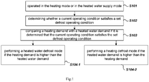
- Fig.1 is a flowchart of a total heat recovery defrosting control method according to the present invention, and the control method includes steps as follows.
- Step S101 the total heat recovery unit is operated in the heating mode or in the heated water supply mode.
- the total recovery unit could automatically work in the heating mode or in the heated water supply mode in different periods of time, or automatically work in the heating mode and the heated water supply mode according to varied heat load of the air-conditioned room or heated water requirements.
- Step S102 determining whether a current operating condition satisfies a set defrost operating condition.
- frost layer will increase thermal resistance of the outdoor finned-tube heat exchanger resulting in a gradual decrease of the amount of heat transferred. But if the frost grows to a certain thickness, the amount of heat transferred will drop significantly, thereby inducing that both of the evaporating pressure and the evaporating temperature of the unit begin to drop at an accelerated rate. Therefore with those features of coil temperature and pressure, dual factors including temperature and time could be used to determine whether a current operating condition satisfies a set defrost operating condition.
- the set defrost operating condition is satisfied if the continuous operating time is greater than or equal to a set operating period and a coil temperature of the outdoor finned-tube heat exchanger is less than or equal to a preset defrost temperature.
- the set operating period is optionally 45 minutes and the preset defrost temperature could be in a range from-8°C to -5°C.
- pressure and time also could be chosen as the dual factors in the set defrost operating condition.
- Other set defrost operating conditions known by the ordinary skills in the art also could be used as the set defrost operating condition.
- Step S103 comparing a heating demand with a heated water demand if it is determined that the current operating condition satisfies the set defrost operating condition, in which the heating load refers to the amount of heat required to warm up medium, such as water for air conditioning and the like, to a preset heating temperature and maintain at the preset heating temperature, while the heated water requirement refers to the amount of heat required to warm up water in a water tank to a preset water temperature and maintain at the preset water temperature.
- the heating load refers to the amount of heat required to warm up medium, such as water for air conditioning and the like
- Step S 104-1 performing a heated water defrost mode if the heating demand is higher than the heated water demand; more precisely the unit is preferably configured to meet the control target of the heating mode but to realize a defrost function with the heat transferred by the heat recovery heat exchanger.
- high-temperature and high-pressure refrigerant vapor discharged from the compressor flows into the outdoor air-side finned-tube heat exchanger and release heat to surrounding so that frost is melted while the high-temperature and high-pressure refrigerant vapor is condensed to medium-temperature liquid refrigerant, and then is supercooled as passing through refrigerant pipeline, an accumulator and an economizer, and is turned to low-temperature and low-pressure liquid refrigerant; the low-temperature and low-pressure liquid refrigerant enters into the heat recovery heat exchanger and transfers heat with water in the water tank; after heat exchange enters into a gas-liquid separator to remove droplets from gaseous refrigerant and then back to the compressor again for compression, thereby completing a refrigeration cycle in the heated water defrost mode.
- the operation of the heating mode with a high priority is guaranteed and less affected, so the user experience could be
- Step S 104-2 performing a heating defrost mode if the heated water demand is higher than the heating demand; more precisely the unit is preferably configured to meet the control target of the heated water supply mode but to realize a defrost function with the heat transferred by the indoor water-side heat exchanger.
- high-temperature and high-pressure refrigerant vapor discharged from the compressor flows into the outdoor air-side finned-tube heat exchanger and release heat to surrounding so that frost is melted while the high-temperature and high-pressure refrigerant vapor is condensed to medium-temperature liquid refrigerant, and then is supercooled as passing through refrigerant pipeline, an accumulator and an economizer, and is turned to low-temperature and low-pressure liquid refrigerant; the low-temperature and low-pressure liquid refrigerant enters into the indoor water-side heat exchanger and transfers heat with medium such as water for air conditioning; after heat exchange enters into a gas-liquid separator to remove droplets from gaseous refrigerant and then back to the compressor again for compression, thereby completing a refrigeration cycle in the heating defrost mode.
- the operation of the heated water supply mode with a high priority is guaranteed and less affected, so the
- a comparison between the heating demand and the heated water demand is performed to select the heat exchanger with less heat demand to fulfill the defrost function, thereby avoiding a large amount of heat loss of heat exchanger in operating mode, so as to minimize the impact on user experience and further guarantee heating demand or heated water demand by users.
- the process to compare the heating demand with the heated water demand includes the following steps.
- Step S201 collecting a current heating set temperature T r and an inlet water temperature T wi at the heat recovery heat exchanger side, wherein the current heating set temperature T r could be a preset temperature input by user, a corrected temperature corrected by a stored algorithm on the basis of the preset temperature input by user, or a given temperature generated by a control algorithm stored in the unit as manufactured according to environmental parameters.
- the heating set temperature T r refers to a target temperature of the water for air conditioning which could achieve ideal environmental parameters of the air-conditioned room in the heating mode.
- the inlet water temperature in the entire total heat recovery unit could be considered consistent and the inlet water temperature T wi on the heat recovery heat exchanger side could be obtained by a temperature sensor set at an inlet of the water tank, which is convenient to realize, the inlet water temperature T wi at the heat recovery heat exchanger side represents a current actual temperature of the water for air conditioning.
- Step S203 collecting a current set temperature of heated water T hr and an outlet water temperature T h at the heat recovery heat exchanger side, wherein the current set temperature of heated water T hr could be preset temperature input by user, a corrected temperature corrected by a stored algorithm on the basis of the preset temperature input by user, or a given temperature generated by a control algorithm stored in the unit as manufactured according to environmental parameters.
- the current set temperature of heated water T hr is the target temperature of heated water that the user requires and the outlet water temperature T h at the heat recovery heat exchanger side represents the temperature of heated water could be supplied currently, wherein the outlet water temperature T h at the heat recovery heat exchanger side could be detected by a temperature sensor arranged at an water outlet of the water tank.
- Step S205-1 if the first temperature difference T d1 is greater than the second temperature difference T d2 , it means that the thermal load that requires to be satisfied by operation in the heating mode is greater than the thermal load that requires to be satisfied by operation in the heated water supply mode, and it could be further determined that the heating demand is higher than the heated water demand, the heat exchanger causing less impact on operation as performing a defrost process is selected, to be specific the heated water defrost mode is executed.
- Step S205-2 if the first temperature difference T d1 is less than the second temperature difference T d2 , it means that the thermal load that requires to be satisfied by operation in the heated water supply mode is greater than the thermal load that requires to be satisfied by operation in the heating mode and it could be further determined that the heated water demand is higher than the heating demand, the heat exchanger causing less impact on operation as performing a defrost process is selected, to be specific the heating defrost mode is executed.
- the process to compare the heating demand with the heated water demand could include the following steps.
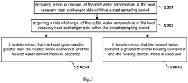
- Step S301 acquiring a rate of change ⁇ T wi of the inlet water temperature at the heat recovery heat exchanger side within a preset sampling period.
- the rate of change of the inlet water temperature at the heat recovery heat exchanger side within the preset sampling period that represents how the temperature at the inlet of the water tank at the heat recovery heat exchanger side changes during a preset period when the unit being normally operated.
- the temperature change at the inlet of the water tank at the heat recovery heat exchanger side accelerates as water circulation in the total heat recovery unit is fast while the temperature change at the inlet of the water tank on the heat exchanger side slows down as water circulation in the total heat recovery unit is slow.
- the temperature change at the inlet of the water tank at the heat recovery heat exchanger side represents water circulation state in the total heat recovery unit, which also could dynamically reflect a heating demand in a period as the unit being normally operated just before the set defrost operating condition is met.
- the acquisition of the rate of change ⁇ T wi of the inlet water temperature at the heat recovery heat exchanger side within a preset sampling period could be realized by the following steps.
- a group of inlet water temperatures at the heat recovery heat exchanger side collected at each set sampling point and a time duration of the preset sampling period are stored in the unit, so further an inlet water temperatureT wi2 at the heat recovery heat exchanger side at a time point when the preset sampling period starts could be retrieved according to the time duration of the set sampling period.
- Step S302 acquiring a rate of change ⁇ T h of the outlet water temperature at the heat recovery heat exchanger side within the preset sampling period.
- the rate of change of the outlet water temperature at the heat recovery heat exchanger side within the preset sampling period that represents how the temperature at the outlet of the water tank at the heat recovery heat exchanger side changes during a preset period when the unit being normally operated.
- the temperature change at the outlet of the water tank at the heat recovery heat exchanger side accelerates while the less heated water used by users, the temperature change at the outlet of the water tank at the heat recovery heat exchanger side slows down.
- the temperature change at the outlet of the water tank at the heat recovery heat exchanger side represents how much heated water used by users, which also could dynamically reflect a heated water demand in a period as the unit being normally operated just before the set defrost operating condition is met.
- the acquisition of the rate of change ⁇ T h of the outlet water temperature at the heat recovery heat exchanger side within the preset sampling period could be realized by the following steps.
- a group of outlet water temperatures at the heat recovery heat exchanger side collected at each set sampling point and a time duration of the preset sampling period are stored in the unit, so further an outlet water temperature T h2 at the heat recovery heat exchanger side at a time point when the preset sampling period starts could be retrieved according to the time duration of the set sampling period.
- Step S303-1 it is determined that the heating demand is greater than the heated water demand if ⁇ T wi > ⁇ T h and the heated water defrost mode is executed.
- Step S303-2 it is determined that the heated water demand is greater than the heating demand if ⁇ T wi ⁇ ⁇ T h and the heating defrost mode is executed.
- the method disclosed in Fig.2 provides an approach to compare and evaluate the heating demand and the heated water demand on the basis of static parameters, such as the current heating set temperature and the current set temperature of heated water; while the method disclosed in Fig.3 provides another approach to compare and evaluate the heating demand and the heated water demand based on dynamic parameters, such as the rate of change of the inlet water temperature and the rate of change of the outlet water temperature.
- static parameters and the dynamic parameters are combined including the following steps.
- Step S403-1 acquiring the rate of change ⁇ T wi of the inlet water temperature at the heat recovery heat exchanger side within the preset sampling period and the rate of change ⁇ T h of the outlet water temperature at the heat recovery heat exchanger side within the preset sampling period if the first temperature differenceT d1 is greater than the second temperature difference T d2 .
- Step S404-1 it is determined that the heating demand is higher than the heated water demand if ⁇ T wi > ⁇ T h and the heated water defrost mode is executed.
- Step S404-2 it is determined that the heated water demand is higher the heating demand if ⁇ T wi ⁇ ⁇ T h as the user's dynamic usage being regarded as priority and the heating defrost mode is executed.
- Step S403-2 acquiring the rate of change ⁇ T wi of the inlet water temperature at the heat recovery heat exchanger side within the preset sampling period and the rate of change ⁇ T h of the outlet water temperature at the heat recovery heat exchanger side within the preset sampling period if the first temperature differenceT d1 is less than the second temperature difference T d2 .
- Step S404-3 it is determined that the heating demand is higher than the heated water demand if ⁇ T wi > ⁇ T h as the user's dynamic usage being regarded as priority and the heated water defrost mode is executed.
- Step S404-4 it is determined that the heated water demand is higher the heating demand if ⁇ T wi ⁇ ⁇ T h and the heating defrost mode is executed.
- the time duration of the preset sampling period is set as 30 minutes. If the dual factors, either time and temperature or time and pressure are configured as the set defrost operating condition, it is preferable to establish the set operating period longer than the preset sampling period so as to ensure a complete and accurate usage cycle could be sampled for further acquiring the rate of change of water temperature and make the evaluation result more precise.
- the coil temperature and pressure of the outdoor exchanger rise after defrost, it is preferably determined that a defrost exit condition is met once they rise to a certain value and the heating mode or the heated water mode is restored automatically.
- Fig.5 discloses a total heat recovery defrosting control system including components as follows.
- a defrosting determination module 101 is configured to determine whether a current operating condition satisfies a set defrost operating condition.
- the set defrost operating condition is satisfied if the continuous operating time is greater than or equal to a set operating period and a coil temperature of the outdoor finned-tube heat exchanger is less than or equal to a preset defrost temperature.
- the set operating period is optionally 45 minutes and the preset defrost temperature could be in a range from-8°C to -5°C.
- pressure and time also could be chosen as the dual factors in the set defrost operating condition.
- Other set defrost operating conditions known by the ordinary skills in the art also could be used as the set defrost operating condition.
- a comparison module 102 is configured to compare a heating demand with a heated water demand if it is determined that the current operating condition satisfies the set defrost operating condition, in which the heating load refers to the amount of heat required to warm up medium, such as water for air conditioning and the like, to a preset heating temperature and maintain at the preset heating temperature, while the heated water requirement refers to the amount of heat required to warm up water in a water tank to a preset water temperature and maintain at the preset water temperature.
- An execution module 103 is configured to perform a heated water defrost mode if the heating demand is higher than the heated water demand or to perform a heating defrost mode if the heated water demand is higher than the heating demand.
- a comparison between the heating demand and the heated water demand is performed to select the heat exchanger with less heat demand to fulfill the defrost function, thereby avoiding a large amount of heat loss of heat exchanger in operating mode, so as to minimize the impact on user experience and further guarantee heating demand or heated water demand by users.
- the invention also provides an air conditioning device.
- the air conditioning device is a total heat recovery unit.
- the total heat recovery unit adopts the total heat recovery defrosting control method.
- the air conditioning device adopting the total heat recovery defrosting control method can achieve the same technical effect.
- An embodiment of the present application also provides a computer storage medium, wherein the computer storage medium is stored in a computer program for electronic data exchange, and the computer program enables the air conditioner to perform part or all of the steps of any method described in the above method embodiment.
- the disclosed device may be implemented in other ways.
- the device embodiments described above are merely illustrative: the division of the above-mentioned units or modules is only a logical function division. In actual implementation, there may be other division methods, for example, multiple units or components may be combined or integrated into another system, or some features can be ignored or not implemented.
- the displayed or discussed mutual coupling or direct coupling or communication connection may be indirect coupling or communication connection through some interfaces, devices or units, and may be in electrical or other forms.
- the units described above as separate components may or may not be physically separated, and the components displayed as units may or may not be physical units, that is to say, they may be located in one physical space, or they may be distributed on multiple network units. Some or all of the units may be selected according to practical requirements to achieve the objectives of the solutions of the embodiments.
- the functional units in the various embodiments of the present application may be integrated into one processing unit, or each unit may exist alone physically, or two or more units may be integrated into one unit.
- the above-mentioned integrated unit can be implemented in the form of hardware or software functional unit.
Landscapes
- Engineering & Computer Science (AREA)
- Mechanical Engineering (AREA)
- General Engineering & Computer Science (AREA)
- Chemical & Material Sciences (AREA)
- Combustion & Propulsion (AREA)
- Signal Processing (AREA)
- Physics & Mathematics (AREA)
- Fuzzy Systems (AREA)
- Mathematical Physics (AREA)
- Thermal Sciences (AREA)
- Air Conditioning Control Device (AREA)
- Heat-Pump Type And Storage Water Heaters (AREA)
Abstract
Description
- The invention belongs to the technical field of air conditioning, and in particular relates to a total heat recovery defrosting control method, a total heat recovery defrosting control system and an air conditioning device.
- An air conditioning device with total heat recovery function refers to an air conditioning unit that integrates functions such as cooling, heating and supplying domestic heated water. In a general sense, this type of air conditioning device includes a compressor, an outdoor air-side fin heat exchanger that exchanges heat with air, a water-side heat exchanger, a total heat recovery heat exchanger that recovers wasted heat, a four-way valve, an electronic expansion valve, an accumulator and a plurality of execution components arranged in the refrigerant system configured to adjust refrigerant flow and directions to perform different functions such as solenoid valves and one-way valves. Based on the arrangements that refrigerant could flow along varied routes and exchange heat with different media in heat exchangers, the air conditioning device with total heat recovery function could have multiple function modes, such as heating mode, cooling mode, heated water supply mode and the like. Chinese Patent (
CN201212721Y ) discloses the refrigerant circulation structure and working process of the air conditioning device with total heat recovery mechanism. - When the air conditioning device with total heat recovery function is operated in the heating mode or in the heated water supply mode, especially under a condition that the outdoor ambient temperature is pretty low, frost may build up on the surface of the outdoor air-side fin heat exchanger. The heat capacity of the outdoor air-side fin heat exchanger is gradually reduced as the thermal resistance increases, which is caused by the accumulation of frost and drops rapidly if the frost grows to a certain thickness. In order to minimize the impact on the operation of air conditioner due to the drop of heat capacity, a corresponding heating defrost mode and a heated water defrost mode are pre-established. When the air conditioning device operates in the heating defrost mode, high-temperature and high-pressure refrigerant discharged from the compressor flows into the outdoor air-side fin heat exchanger through the four-way valve to defrost and condenses to a medium-temperature and medium-pressure liquid refrigerant; the medium-temperature and medium-pressure refrigerant is supercooled by passing through components such as the accumulator and an economizer and changes into low-temperature and low-pressure refrigerant through the throttling device for extracting heat from water for air conditioning in the indoor water-side heat exchanger. When the air conditioning device operates in the heated water defrost mode, high-temperature and high-pressure refrigerant discharged from the compressor flows into the outdoor air-side fin heat exchanger through the four-way valve to defrost and is condensed to medium-temperature and medium-pressure liquid refrigerant; the medium-temperature and medium-pressure liquid refrigerant is supercooled by passing through components such as the accumulator and the economizer and changes into low-temperature and low-pressure refrigerant through the throttling device; the low-temperature and low-pressure refrigerant flows to the heat recovery heat exchanger. It is obvious that either in the heating defrost mode or in the heated water defrost mode, defrost is relied on the sacrifice heat produced by the water-side heat exchanger or by the heat recovery heat exchanger and it inevitably affects user experience.
- The above-mentioned information is only used to explain the background of the present invention and it may include the prior art that is not known to those of ordinary skill in the art.
- Aiming at solving the problem that frost may form as an air conditioning device with a total heat recovery function being operated in heating mode or in heated water supply mode in winter but the traditional defrost method may consume the amount of heat exchange of the system and deteriorate user's experience, a total heat recovery defrosting control method is provided by the present invention.
- In order to achieve the above-mentioned purpose of the present invention, the following technical solutions are adopted.
- A total heat recovery defrosting control method comprises: a total heat recovery unit is operated in a heating mode or in a heated water supply mode; determining whether a current operating condition satisfies a set defrost operating condition; comparing a heating demand with a heated water demand if it is determined that the current operating condition satisfies the set defrost operating condition, performing a heated water defrost mode if the heating demand is higher than the heated water demand; or performing a heating defrost mode if the heated water demand is higher than the heating demand.
- Further the process that comparing the heating demand with the heated water demand includes: collecting a current heating set temperature Tr and an inlet water temperature Twi at the heat recovery heat exchanger side; calculating a first temperature differenceTd1, wherein Td1 = Tr - Twi; collecting a current set temperature of heated water Thr and an outlet water temperature Th at the heat recovery heat exchanger side; calculating a second temperature difference Td2, wherein Td2 = Thr - Th; if the first temperature difference Td1 is greater than the second temperature difference Td2, it is determined that the heating demand is higher than the heated water demand and the heated water defrost mode is executed; or if the first temperature difference Td1 is less than the second temperature difference Td2, it is determined that the heated water demand is higher than the heating demand and the heating defrost mode is executed.
- Alternatively the process that comparing the heating demand with the heated water demand includes: acquiring a rate of change ΔTwi of the inlet water temperature at the heat recovery heat exchanger side within a preset sampling period; acquiring a rate of change ΔTh of the outlet water temperature at the heat recovery heat exchanger side within a preset sampling period; it is determined that the heating demand is greater than the heated water demand if ΔTwi > ΔTh and the heated water defrost mode is executed; or it is determined that the heated water demand is greater than the heating demand if ΔTwi < ΔTh and the heating defrost mode is executed.
- Alternatively the process that comparing the heating demand with the heated water demand includes: collecting the current heating set temperature Tr and the inlet water temperature Twi at the heat recovery heat exchanger side; calculating the first temperature differenceTd1, whereinTd1 = Tr - Twi; collecting a current set temperature of heated water Thr and an outlet water temperature Th at the heat recovery heat exchanger side; calculating a second temperature difference Td2, wherein Td2 = Thr - Th; acquiring the rate of change ΔTwi of the inlet water temperature at the heat recovery heat exchanger side within the preset sampling period and the rate of change ΔTh of the outlet water temperature at the heat recovery heat exchanger side within the preset sampling period if the first temperature differenceTd1 is greater than the second temperature difference Td2; it is determined that the heating demand is higher than the heated water demand if ΔTwi > ΔTh and the heated water defrost mode is executed; it is determined that the heated water demand is higher the heating demand if ΔTwi < ΔTh and the heating defrost mode is executed; acquiring the rate of change ΔTwi of the inlet water temperature at the heat recovery heat exchanger side within the preset sampling period and the rate of change ΔTh of the outlet water temperature at the heat recovery heat exchanger side within the preset sampling period if the first temperature differenceTd1 is less than the second temperature difference Td2; it is determined that the heating demand is higher than the heated water demand if ΔTwi > ΔTh and the heated water defrost mode is executed; it is determined that the heated water demand is higher the heating demand if ΔTwi < ΔTh and the heating defrost mode is executed.
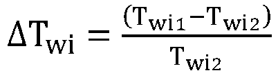
- Further the acquisition of the rate of change ΔTwi of the inlet water temperature at the heat recovery heat exchanger side within a preset sampling period including: obtaining an inlet water temperature Twi1 at the heat recovery heat exchanger side at a time point when the preset sampling period ends, wherein the time point when the preset sampling period ends is the time point when it is determined that the set defrost operating condition is met; obtaining an inlet water temperatureTwi2 at the heat recovery heat exchanger side at a time point when the preset sampling period starts; and calculating the rate of change ΔTwi of the inlet water temperature at the heat recovery heat exchanger side;

- Further the acquisition of the rate of change ΔTh of the outlet water temperature at the heat recovery heat exchanger side within the preset sampling period including: obtaining an outlet water temperature Th1 at the heat recovery heat exchanger side a time point when the preset sampling period ends, wherein the time point when the preset sampling period ends is the time point when it is determined that the set defrost operating condition is met; obtaining an outlet water temperature Th2 at the heat recovery heat exchanger side at a time point when the preset sampling period starts; and calculating the rate of change ΔTh of the outlet water temperature at the heat recovery heat exchanger side;

- Preferably the time duration of the preset sampling period is 30 minutes.
- Further the set defrost operating condition includes: continuous operating time is greater than or equal to a set operating period and a coil temperature of an outdoor heat exchanger is less than or equal to a preset defrost temperature, wherein the set operating period is greater than the preset sampling period.
- Another aspect of the present invention provides a total heat recovery defrosting control system including: a defrosting determination module configured to determine whether a current operating condition satisfies a set defrost operating condition; a comparison module configured to compare a heating demand with a heated water demand; and an execution module configured to perform a heated water defrost mode if the heating demand is higher than the heated water demand or to perform a heating defrost mode if the heated water demand is higher than the heating demand.
- Another aspect of the present invention provides air conditioning device, which is a total heat recovery unit; the air conditioning device applies to a total heat recovery defrosting control method; wherein the total heat recovery defrosting control method comprises: a total heat recovery unit is operated in a heating mode or in a heated water supply mode; determining whether a current operating condition satisfies a set defrost operating condition; comparing a heating demand with a heated water demand if it is determined that the current operating condition satisfies the set defrost operating condition, performing a heated water defrost mode if the heating demand is higher than the heated water demand; or performing a heating defrost mode if the heated water demand is higher than the heating demand.
- Compared with the prior art, the advantages and positive effects of the present invention are: a comparison between the heating demand and the heated water demand is performed to select the heat exchanger with less heat demand to fulfill the defrost function, thereby avoiding a large amount of heat loss of heat exchanger in operating mode, so as to minimize the impact on user experience and further guarantee heating demand or heated water demand by users.
- After reading the specific embodiments of the present invention in conjunction with the accompanying drawings, other features and advantages of the present invention will become clearer.
- In order to clearly explain embodiments of the present invention or technical solutions in the prior art, at first drawings related to description of the embodiments or the prior art will be briefly introduced as follows. It is obvious that the drawings are described here are part of embodiments of the present invention; for those ordinary skill in the art other drawings could be obtained based on these without any creative work.
-
Fig.1 is a flowchart of a total heat recovery defrosting control method according to one aspect of the present invention; -
Fig.2 is a flowchart of a first alternative method to compare the heating demand and the heated water demand; -
Fig.3 is a flowchart of a second alternative method to compare the heating demand and the heated water demand; -
Fig.4 is a flowchart of a third alternative method to compare the heating demand and the heated water demand; -
Fig.5 is a schematic block diagram of a total heat recovery defrosting control system according to another aspect of the present invention. - In order to give a full explanation of the objectives, technical solutions and advantages of embodiments of the present invention, the technical solutions disclosed by the present embodiments will be clearly and completely described based on the accompanying drawings.
- Terms "first", "second", "third" and the like in the specification, claims and drawings in the present invention are used to distinguish different objects, rather than to describe a specific order. In addition, terms "including", "having" and their variations are not exclusive; such as a process or a method that includes a series of steps, or a system, a product or a device that includes a plurality of units is not restricted to the steps or the units concerned, but optionally further includes steps or units not listed, or optionally includes other inherent steps or units of the process, the method, the product or the device.
- "Embodiment" in the present invention means that specific features, structures or properties described in one embodiment could be included in one or more embodiments. The term in various positions of the specification does not necessarily refer to one same embodiment, nor is it an independent embodiment or an alternative embodiment mutually exclusive with other embodiments. Those skilled in the art could understand that the embodiments described could be combined with other embodiments.
- A brief introduction of a total heat recovery unit is provided at the beginning. The total heat recovery unit could operate in a cooling mode, a heating mode and a heated water supply mode. It is necessary to defrost an outdoor heat exchanger as being operated in the heating mode or in the heated water supply mode.
- When the total heat recovery unit is operated in the heated water supply mode, low-temperature and low-pressure refrigerant vapor is compressed by a compressor into high-temperature and high-pressure superheated refrigerant vapor. Corresponding valves in the refrigeration cycle are open to enable the high-temperature and high-pressure superheated refrigerant vapor to flow into a heat recovery heat exchanger to exchange heat with medium on the heat recovery heat exchanger side; usually the medium on the heat recovery heat exchanger side is water in a water tank that is heated to a preset water temperature; while the high-temperature and high-pressure superheated refrigerant vapor is condensed to medium-temperature and high-pressure liquid refrigerant within the heat recovery heat exchanger, and is further guided to flow through an accumulator, a filter and an expansion valve changing to low-temperature and low-pressure liquid. The low-temperature and low-pressure liquid then flows into an outdoor finned-tube heat exchanger through corresponding refrigerant pipeline to exchange heat with outdoor air blown by a switch-on indoor fan. The low-temperature and low-pressure liquid evaporates into low-temperature and low-pressure gaseous refrigerant, and back to the compressor through a four-way valve to complete a refrigerant cycle of the heated water supply mode.
- When the total heat recovery unit is operated in the heating mode, low-temperature and low-pressure refrigerant vapor is compressed by the compressor into high-temperature and high-pressure superheated refrigerant vapor. Corresponding valves in the refrigeration cycle are open to enable the high-temperature and high-pressure superheated refrigerant vapor to flow into an indoor water-side heat exchanger through the four-way valve and exchange heat with water for air conditioning and warm the water for air conditioning up to a preset heating temperature; while the high-temperature and high-pressure superheated refrigerant vapor is condensed to medium-temperature and high-pressure liquid refrigerant, and is further guided to flow through refrigerant pipeline, the filter and the expansion valve to changing to low-temperature and low-pressure liquid. The low-temperature and low-pressure liquid then flows into an outdoor finned-tube heat exchanger through corresponding refrigerant pipeline to exchange heat with outdoor air blown by a switch-on indoor fan. The low-temperature and low-pressure liquid evaporates into low-temperature and low-pressure gaseous refrigerant, and back to the compressor through the four-way valve to complete a refrigerant cycle of the heating mode.
-
Fig.1 is a flowchart of a total heat recovery defrosting control method according to the present invention, and the control method includes steps as follows. - Step S101, the total heat recovery unit is operated in the heating mode or in the heated water supply mode. In winter, the total recovery unit could automatically work in the heating mode or in the heated water supply mode in different periods of time, or automatically work in the heating mode and the heated water supply mode according to varied heat load of the air-conditioned room or heated water requirements.
- Step S102, determining whether a current operating condition satisfies a set defrost operating condition. The formation of frost layer will increase thermal resistance of the outdoor finned-tube heat exchanger resulting in a gradual decrease of the amount of heat transferred. But if the frost grows to a certain thickness, the amount of heat transferred will drop significantly, thereby inducing that both of the evaporating pressure and the evaporating temperature of the unit begin to drop at an accelerated rate. Therefore with those features of coil temperature and pressure, dual factors including temperature and time could be used to determine whether a current operating condition satisfies a set defrost operating condition. For example, it is determined that the set defrost operating condition is satisfied if the continuous operating time is greater than or equal to a set operating period and a coil temperature of the outdoor finned-tube heat exchanger is less than or equal to a preset defrost temperature. The set operating period is optionally 45 minutes and the preset defrost temperature could be in a range from-8°C to -5°C. In addition to selecting the temperature and time as the dual factors, pressure and time also could be chosen as the dual factors in the set defrost operating condition. Other set defrost operating conditions known by the ordinary skills in the art also could be used as the set defrost operating condition.
- Step S103, comparing a heating demand with a heated water demand if it is determined that the current operating condition satisfies the set defrost operating condition, in which the heating load refers to the amount of heat required to warm up medium, such as water for air conditioning and the like, to a preset heating temperature and maintain at the preset heating temperature, while the heated water requirement refers to the amount of heat required to warm up water in a water tank to a preset water temperature and maintain at the preset water temperature.
- Step S 104-1, performing a heated water defrost mode if the heating demand is higher than the heated water demand; more precisely the unit is preferably configured to meet the control target of the heating mode but to realize a defrost function with the heat transferred by the heat recovery heat exchanger. When the heated water defrost mode is performed, controlled by the four-way valve, high-temperature and high-pressure refrigerant vapor discharged from the compressor flows into the outdoor air-side finned-tube heat exchanger and release heat to surrounding so that frost is melted while the high-temperature and high-pressure refrigerant vapor is condensed to medium-temperature liquid refrigerant, and then is supercooled as passing through refrigerant pipeline, an accumulator and an economizer, and is turned to low-temperature and low-pressure liquid refrigerant; the low-temperature and low-pressure liquid refrigerant enters into the heat recovery heat exchanger and transfers heat with water in the water tank; after heat exchange enters into a gas-liquid separator to remove droplets from gaseous refrigerant and then back to the compressor again for compression, thereby completing a refrigeration cycle in the heated water defrost mode. During this process, the operation of the heating mode with a high priority is guaranteed and less affected, so the user experience could be ensured to the greatest extent.
- Step S 104-2, performing a heating defrost mode if the heated water demand is higher than the heating demand; more precisely the unit is preferably configured to meet the control target of the heated water supply mode but to realize a defrost function with the heat transferred by the indoor water-side heat exchanger. When the heating defrost mode is performed, controlled by the four-way valve, high-temperature and high-pressure refrigerant vapor discharged from the compressor flows into the outdoor air-side finned-tube heat exchanger and release heat to surrounding so that frost is melted while the high-temperature and high-pressure refrigerant vapor is condensed to medium-temperature liquid refrigerant, and then is supercooled as passing through refrigerant pipeline, an accumulator and an economizer, and is turned to low-temperature and low-pressure liquid refrigerant; the low-temperature and low-pressure liquid refrigerant enters into the indoor water-side heat exchanger and transfers heat with medium such as water for air conditioning; after heat exchange enters into a gas-liquid separator to remove droplets from gaseous refrigerant and then back to the compressor again for compression, thereby completing a refrigeration cycle in the heating defrost mode. During this process, the operation of the heated water supply mode with a high priority is guaranteed and less affected, so the user experience could be ensured to the greatest extent.
- In the above-mentioned total heat recovery defrosting control method, a comparison between the heating demand and the heated water demand is performed to select the heat exchanger with less heat demand to fulfill the defrost function, thereby avoiding a large amount of heat loss of heat exchanger in operating mode, so as to minimize the impact on user experience and further guarantee heating demand or heated water demand by users.
- Referring to structure features of the total heat recovery unit, as shown in
Fig.2 , the process to compare the heating demand with the heated water demand includes the following steps. - Step S201, collecting a current heating set temperature Tr and an inlet water temperature Twi at the heat recovery heat exchanger side, wherein the current heating set temperature Tr could be a preset temperature input by user, a corrected temperature corrected by a stored algorithm on the basis of the preset temperature input by user, or a given temperature generated by a control algorithm stored in the unit as manufactured according to environmental parameters. Specifically, the heating set temperature Tr refers to a target temperature of the water for air conditioning which could achieve ideal environmental parameters of the air-conditioned room in the heating mode. Since the inlet water temperature in the entire total heat recovery unit could be considered consistent and the inlet water temperature Twi on the heat recovery heat exchanger side could be obtained by a temperature sensor set at an inlet of the water tank, which is convenient to realize, the inlet water temperature Twi at the heat recovery heat exchanger side represents a current actual temperature of the water for air conditioning.
- Step S202, calculating a first temperature difference Td1, wherein Td1 = Tr - Twi which represents a deviation of a real-time temperature from a target temperature in the heating mode, in other word the thermal load that requires to be satisfied by operation in the heating mode.
- Step S203, collecting a current set temperature of heated water Thr and an outlet water temperature Th at the heat recovery heat exchanger side, wherein the current set temperature of heated water Thr could be preset temperature input by user, a corrected temperature corrected by a stored algorithm on the basis of the preset temperature input by user, or a given temperature generated by a control algorithm stored in the unit as manufactured according to environmental parameters. Specifically, the current set temperature of heated water Thr is the target temperature of heated water that the user requires and the outlet water temperature Th at the heat recovery heat exchanger side represents the temperature of heated water could be supplied currently, wherein the outlet water temperature Th at the heat recovery heat exchanger side could be detected by a temperature sensor arranged at an water outlet of the water tank.
- Step S204: calculating a second temperature difference Td2, wherein Td2 = Thr - Th which represents a deviation of a real-time water temperature from a target water temperature in the heated water supply mode, in other word the thermal load that requires to be satisfied by operation in the heated water supply mode.
- Step S205-1: if the first temperature difference Td1 is greater than the second temperature difference Td2, it means that the thermal load that requires to be satisfied by operation in the heating mode is greater than the thermal load that requires to be satisfied by operation in the heated water supply mode, and it could be further determined that the heating demand is higher than the heated water demand, the heat exchanger causing less impact on operation as performing a defrost process is selected, to be specific the heated water defrost mode is executed.
- Step S205-2, if the first temperature difference Td1 is less than the second temperature difference Td2, it means that the thermal load that requires to be satisfied by operation in the heated water supply mode is greater than the thermal load that requires to be satisfied by operation in the heating mode and it could be further determined that the heated water demand is higher than the heating demand, the heat exchanger causing less impact on operation as performing a defrost process is selected, to be specific the heating defrost mode is executed.
- Referring to
Fig.3 , the process to compare the heating demand with the heated water demand could include the following steps. - Step S301: acquiring a rate of change ΔTwi of the inlet water temperature at the heat recovery heat exchanger side within a preset sampling period.
- To be specific the rate of change of the inlet water temperature at the heat recovery heat exchanger side within the preset sampling period that represents how the temperature at the inlet of the water tank at the heat recovery heat exchanger side changes during a preset period when the unit being normally operated. Practically the temperature change at the inlet of the water tank at the heat recovery heat exchanger side accelerates as water circulation in the total heat recovery unit is fast while the temperature change at the inlet of the water tank on the heat exchanger side slows down as water circulation in the total heat recovery unit is slow. Hence the temperature change at the inlet of the water tank at the heat recovery heat exchanger side represents water circulation state in the total heat recovery unit, which also could dynamically reflect a heating demand in a period as the unit being normally operated just before the set defrost operating condition is met.
- The acquisition of the rate of change ΔTwi of the inlet water temperature at the heat recovery heat exchanger side within a preset sampling period could be realized by the following steps.
- Obtaining an inlet water temperature Twi1 at the heat recovery heat exchanger side at a time point when the preset sampling period ends; and preferably the time point when the preset sampling period ends is the time point when it is determined that the set defrost operating condition is met.
- A group of inlet water temperatures at the heat recovery heat exchanger side collected at each set sampling point and a time duration of the preset sampling period are stored in the unit, so further an inlet water temperatureTwi2 at the heat recovery heat exchanger side at a time point when the preset sampling period starts could be retrieved according to the time duration of the set sampling period.
- Calculating the rate of change ΔTwi of the inlet water temperature at the heat recovery heat exchanger side;
- Step S302: acquiring a rate of change ΔTh of the outlet water temperature at the heat recovery heat exchanger side within the preset sampling period.
- To be specific the rate of change of the outlet water temperature at the heat recovery heat exchanger side within the preset sampling period that represents how the temperature at the outlet of the water tank at the heat recovery heat exchanger side changes during a preset period when the unit being normally operated. Practically the more heated water used by users, the temperature change at the outlet of the water tank at the heat recovery heat exchanger side accelerates while the less heated water used by users, the temperature change at the outlet of the water tank at the heat recovery heat exchanger side slows down. Hence the temperature change at the outlet of the water tank at the heat recovery heat exchanger side represents how much heated water used by users, which also could dynamically reflect a heated water demand in a period as the unit being normally operated just before the set defrost operating condition is met.
- The acquisition of the rate of change ΔTh of the outlet water temperature at the heat recovery heat exchanger side within the preset sampling period could be realized by the following steps.
- Obtaining an outlet water temperature Th1 at the heat recovery heat exchanger side a time point when the preset sampling period ends; and preferably the time point when the preset sampling period ends is the time point when it is determined that the set defrost operating condition is met.
- A group of outlet water temperatures at the heat recovery heat exchanger side collected at each set sampling point and a time duration of the preset sampling period are stored in the unit, so further an outlet water temperature Th2 at the heat recovery heat exchanger side at a time point when the preset sampling period starts could be retrieved according to the time duration of the set sampling period.
- Calculating the rate of change ΔTh of the outlet water temperature at the heat recovery heat exchanger side;

- Step S303-1: it is determined that the heating demand is greater than the heated water demand if ΔTwi > ΔTh and the heated water defrost mode is executed.
- Step S303-2, it is determined that the heated water demand is greater than the heating demand if ΔTwi < ΔTh and the heating defrost mode is executed.
- In the above two embodiments, the method disclosed in
Fig.2 provides an approach to compare and evaluate the heating demand and the heated water demand on the basis of static parameters, such as the current heating set temperature and the current set temperature of heated water; while the method disclosed inFig.3 provides another approach to compare and evaluate the heating demand and the heated water demand based on dynamic parameters, such as the rate of change of the inlet water temperature and the rate of change of the outlet water temperature. In order to provide a more accurate approach to evaluate the heating demand and the heated water demand, another method is disclosed inFig.4 in which the static parameters and the dynamic parameters are combined including the following steps. - Step S401, collecting the current heating set temperature Tr and the inlet water temperature Twi at the heat recovery heat exchanger side; calculating the first temperature differenceTd1, whereinTd1 = Tr - Twi.
- Step S402, collecting a current set temperature of heated water Thr and an outlet water temperature Th at the heat recovery heat exchanger side; calculating a second temperature difference Td2, wherein Td2 = Thr - Th;
- Step S403-1, acquiring the rate of change ΔTwi of the inlet water temperature at the heat recovery heat exchanger side within the preset sampling period and the rate of change ΔTh of the outlet water temperature at the heat recovery heat exchanger side within the preset sampling period if the first temperature differenceTd1 is greater than the second temperature difference Td2.
- Step S404-1, it is determined that the heating demand is higher than the heated water demand if ΔTwi > ΔTh and the heated water defrost mode is executed.
- Step S404-2, it is determined that the heated water demand is higher the heating demand if ΔTwi < ΔTh as the user's dynamic usage being regarded as priority and the heating defrost mode is executed.
- Step S403-2, acquiring the rate of change ΔTwi of the inlet water temperature at the heat recovery heat exchanger side within the preset sampling period and the rate of change ΔTh of the outlet water temperature at the heat recovery heat exchanger side within the preset sampling period if the first temperature differenceTd1 is less than the second temperature difference Td2.
- Step S404-3, it is determined that the heating demand is higher than the heated water demand if ΔTwi > ΔTh as the user's dynamic usage being regarded as priority and the heated water defrost mode is executed.
- Step S404-4, it is determined that the heated water demand is higher the heating demand if ΔTwi < ΔTh and the heating defrost mode is executed.
- In the three evaluation methods disclosed above, it is preferable to set the time duration of the preset sampling period as 30 minutes. If the dual factors, either time and temperature or time and pressure are configured as the set defrost operating condition, it is preferable to establish the set operating period longer than the preset sampling period so as to ensure a complete and accurate usage cycle could be sampled for further acquiring the rate of change of water temperature and make the evaluation result more precise.
- The coil temperature and pressure of the outdoor exchanger rise after defrost, it is preferably determined that a defrost exit condition is met once they rise to a certain value and the heating mode or the heated water mode is restored automatically.
-
Fig.5 discloses a total heat recovery defrosting control system including components as follows. - A defrosting
determination module 101 is configured to determine whether a current operating condition satisfies a set defrost operating condition. - For example, it is determined that the set defrost operating condition is satisfied if the continuous operating time is greater than or equal to a set operating period and a coil temperature of the outdoor finned-tube heat exchanger is less than or equal to a preset defrost temperature. The set operating period is optionally 45 minutes and the preset defrost temperature could be in a range from-8°C to -5°C. In addition to selecting the temperature and time as the dual factors, pressure and time also could be chosen as the dual factors in the set defrost operating condition. Other set defrost operating conditions known by the ordinary skills in the art also could be used as the set defrost operating condition.
- A
comparison module 102 is configured to compare a heating demand with a heated water demand if it is determined that the current operating condition satisfies the set defrost operating condition, in which the heating load refers to the amount of heat required to warm up medium, such as water for air conditioning and the like, to a preset heating temperature and maintain at the preset heating temperature, while the heated water requirement refers to the amount of heat required to warm up water in a water tank to a preset water temperature and maintain at the preset water temperature. - An
execution module 103 is configured to perform a heated water defrost mode if the heating demand is higher than the heated water demand or to perform a heating defrost mode if the heated water demand is higher than the heating demand. - In the above-mentioned total heat recovery defrosting control system, a comparison between the heating demand and the heated water demand is performed to select the heat exchanger with less heat demand to fulfill the defrost function, thereby avoiding a large amount of heat loss of heat exchanger in operating mode, so as to minimize the impact on user experience and further guarantee heating demand or heated water demand by users.
- The invention also provides an air conditioning device. The air conditioning device is a total heat recovery unit. The total heat recovery unit adopts the total heat recovery defrosting control method. For the specific steps of the total heat recovery defrosting control method, please refer to the detailed description of any of the foregoing embodiments, which will not be repeated here. The air conditioning device adopting the total heat recovery defrosting control method can achieve the same technical effect.
- An embodiment of the present application also provides a computer storage medium, wherein the computer storage medium is stored in a computer program for electronic data exchange, and the computer program enables the air conditioner to perform part or all of the steps of any method described in the above method embodiment.
- In the above-mentioned embodiments, the description of each embodiment has its own emphasis. For parts that are not described in detail in an embodiment, reference may be made to related descriptions of other embodiments.
- In the several embodiments provided in this application, it should be understood that the disclosed device may be implemented in other ways. For example, the device embodiments described above are merely illustrative: the division of the above-mentioned units or modules is only a logical function division. In actual implementation, there may be other division methods, for example, multiple units or components may be combined or integrated into another system, or some features can be ignored or not implemented. In addition, the displayed or discussed mutual coupling or direct coupling or communication connection may be indirect coupling or communication connection through some interfaces, devices or units, and may be in electrical or other forms.
- The units described above as separate components may or may not be physically separated, and the components displayed as units may or may not be physical units, that is to say, they may be located in one physical space, or they may be distributed on multiple network units. Some or all of the units may be selected according to practical requirements to achieve the objectives of the solutions of the embodiments.
- In addition, the functional units in the various embodiments of the present application may be integrated into one processing unit, or each unit may exist alone physically, or two or more units may be integrated into one unit. The above-mentioned integrated unit can be implemented in the form of hardware or software functional unit.
- Finally, it should be noted that the above embodiments are only used to illustrate the technical solutions of the present invention, not to limit it; although the present invention has been described in detail with reference to the foregoing embodiments, those of ordinary skill in the art should understand that: The technical solutions recorded in the foregoing embodiments are modified, or some of the technical features are equivalently replaced; these modifications or replacements do not cause the essence of the corresponding technical solutions to deviate from the spirit and scope of the technical solutions of the embodiments of the present invention.
Claims (10)
- A total heat recovery defrosting control method, characterized in that the method comprises:a total heat recovery unit is operated in a heating mode or in a heated water supply mode;determining whether a current operating condition satisfies a set defrost operating condition;comparing a heating demand with a heated water demand if it is determined that the current operating condition satisfies the set defrost operating condition,performing a heated water defrost mode if the heating demand is higher than the heated water demand; orperforming a heating defrost mode if the heated water demand is higher than the heating demand.
- The total heat recovery defrosting control method according to claim 1, characterized in that, comparing the heating demand with the heated water demand including:collecting a current heating set temperature Tr and an inlet water temperature Twi at the heat recovery heat exchanger side;calculating a first temperature differenceTd1, wherein Td1 = Tr - Twi;collecting a current set temperature of heated water Thr and an outlet water temperature Th at the heat recovery heat exchanger side;calculating a second temperature difference Td2, wherein Td2 = Thr - Th;if the first temperature difference Td1 is greater than the second temperature difference Td2, it is determined that the heating demand is higher than the heated water demand and the heated water defrost mode is executed; orif the first temperature difference Td1 is less than the second temperature difference Td2, it is determined that the heated water demand is higher than the heating demand and the heating defrost mode is executed.
- The total heat recovery defrosting control method according to claim 1, characterized in that, comparing the heating demand with the heated water demand including:acquiring a rate of change ΔTwi of the inlet water temperature at the heat recovery heat exchanger side within a preset sampling period;acquiring a rate of change ΔTh of the outlet water temperature at the heat recovery heat exchanger side within a preset sampling period;it is determined that the heating demand is greater than the heated water demand if ΔTwi > ΔTh and the heated water defrost mode is executed; orit is determined that the heated water demand is greater than the heating demand if ΔTwi < ΔTh and the heating defrost mode is executed.
- The total heat recovery defrosting control method according to claim 1, characterized in that, comparing the heating demand with the heated water demand including:collecting the current heating set temperature Tr and the inlet water temperature Twi at the heat recovery heat exchanger side; calculating the first temperature difference Td1 , whereinTd1 = Tr - Twi;collecting a current set temperature of heated water Thr and an outlet water temperature Th at the heat recovery heat exchanger side; calculating a second temperature difference Td2, wherein Td2 = Thr - Th;acquiring the rate of change ΔTwi of the inlet water temperature at the heat recovery heat exchanger side within the preset sampling period and the rate of change ΔTh of the outlet water temperature at the heat recovery heat exchanger side within the preset sampling period if the first temperature differenceTd1 is greater than the second temperature difference Td2; it is determined that the heating demand is higher than the heated water demand if ΔTwi > ΔTh and the heated water defrost mode is executed; it is determined that the heated water demand is higher the heating demand if ΔTwi < ΔTh and the heating defrost mode is executed;acquiring the rate of change ΔTwi of the inlet water temperature at the heat recovery heat exchanger side within the preset sampling period and the rate of change ΔTh of the outlet water temperature at the heat recovery heat exchanger side within the preset sampling period if the first temperature differenceTd1 is less than the second temperature difference Td2; it is determined that the heating demand is higher than the heated water demand if ΔTwi > ΔTh and the heated water defrost mode is executed; it is determined that the heated water demand is higher the heating demand if ΔTwi < ΔTh and the heating defrost mode is executed.
- The total heat recovery defrosting control method according to claim 3 or 4, characterized in that,
the acquisition of the rate of change ΔTwi of the inlet water temperature at the heat recovery heat exchanger side within a preset sampling period including:obtaining an inlet water temperature Twi1 at the heat recovery heat exchanger side at a time point when the preset sampling period ends, wherein the time point when the preset sampling period ends is the time point when it is determined that the set defrost operating condition is met;obtaining an inlet water temperatureTwi2 at the heat recovery heat exchanger side at a time point when the preset sampling period starts; andcalculating the rate of change ΔTwi of the inlet water temperature at the heat recovery heat exchanger side,
- The total heat recovery defrosting control method according to claim 5, characterized in that,
the acquisition of the rate of change ΔTh of the outlet water temperature at the heat recovery heat exchanger side within the preset sampling period including:obtaining an outlet water temperature Th1 at the heat recovery heat exchanger side a time point when the preset sampling period ends, wherein the time point when the preset sampling period ends is the time point when it is determined that the set defrost operating condition is met;obtaining an outlet water temperature Th2 at the heat recovery heat exchanger side at a time point when the preset sampling period starts; andcalculating the rate of change ΔTh of the outlet water temperature at the heat recovery heat exchanger side;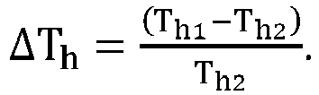
- The total heat recovery defrosting control method according to claim 6, characterized in that,
the time duration of the preset sampling period is 30 minutes. - The total heat recovery defrosting control method according to claim 6, characterized in that,
the set defrost operating condition includes:
continuous operating time is greater than or equal to a set operating period and a coil temperature of an outdoor heat exchanger is less than or equal to a preset defrost temperature, wherein the set operating period is greater than the preset sampling period. - A total heat recovery defrosting control system, characterized in that the system includes:a defrosting determination module configured to determine whether a current operating condition satisfies a set defrost operating condition;a comparison module configured to compare a heating demand with a heated water demand; andan execution module configured to perform a heated water defrost mode if the heating demand is higher than the heated water demand or to perform a heating defrost mode if the heated water demand is higher than the heating demand.
- An air conditioning device, which is a total heat recovery unit, characterized in that, a total heat recovery defrosting control method according to any one of claim 1 to 9 is applied to.
Applications Claiming Priority (2)
| Application Number | Priority Date | Filing Date | Title |
|---|---|---|---|
| CN201910837881.5A CN112443934B (en) | 2019-09-05 | 2019-09-05 | Full heat recovery defrosting control method, control system and air conditioning device |
| PCT/CN2020/070797 WO2021042654A1 (en) | 2019-09-05 | 2020-01-08 | Total heat recovery defrosting control method and control device, and air conditioning apparatus |
Publications (4)
| Publication Number | Publication Date |
|---|---|
| EP4027070A1 true EP4027070A1 (en) | 2022-07-13 |
| EP4027070A4 EP4027070A4 (en) | 2022-10-26 |
| EP4027070C0 EP4027070C0 (en) | 2023-09-13 |
| EP4027070B1 EP4027070B1 (en) | 2023-09-13 |
Family
ID=74733169
Family Applications (1)
| Application Number | Title | Priority Date | Filing Date |
|---|---|---|---|
| EP20860254.0A Active EP4027070B1 (en) | 2019-09-05 | 2020-01-08 | Total heat recovery defrosting control method and control device, and air conditioning apparatus |
Country Status (3)
| Country | Link |
|---|---|
| EP (1) | EP4027070B1 (en) |
| CN (1) | CN112443934B (en) |
| WO (1) | WO2021042654A1 (en) |
Cited By (1)
| Publication number | Priority date | Publication date | Assignee | Title |
|---|---|---|---|---|
| CN119573223A (en) * | 2023-09-06 | 2025-03-07 | 海信空调有限公司 | air conditioner |
Families Citing this family (6)
| Publication number | Priority date | Publication date | Assignee | Title |
|---|---|---|---|---|
| CN113108433A (en) * | 2021-03-23 | 2021-07-13 | 珠海格力电器股份有限公司 | Control method of multi-split air conditioning system |
| CN113432352B (en) * | 2021-06-22 | 2023-02-21 | 山东和同信息科技股份有限公司 | A method and system for air source heat pump defrosting control based on 5G Internet of Things technology |
| EP4177301B1 (en) | 2021-11-03 | 2025-07-09 | Covestro Deutschland AG | Polyphosphazene and moulding composition containing same |
| CN116972577B (en) * | 2023-08-03 | 2026-01-23 | 珠海格力电器股份有限公司 | Control method, control device, heat pump unit and computer readable storage medium |
| CN117109126B (en) * | 2023-09-05 | 2026-03-20 | 珠海格力节能环保制冷技术研究中心有限公司 | Defrosting control method, control device and computer-readable storage medium |
| CN121048319B (en) * | 2025-10-30 | 2026-03-24 | 珠海格力电器股份有限公司 | Defrosting control methods for heat recovery units and heat recovery units |
Family Cites Families (13)
| Publication number | Priority date | Publication date | Assignee | Title |
|---|---|---|---|---|
| JPS5946446A (en) * | 1982-09-10 | 1984-03-15 | Matsushita Electric Ind Co Ltd | Heat pump type water heater |
| JP4257351B2 (en) * | 2006-08-07 | 2009-04-22 | ヤンマー株式会社 | Engine driven heat pump |
| CN201212721Y (en) | 2007-08-03 | 2009-03-25 | 深圳麦克维尔空调有限公司 | An air conditioner full heat recovery unit |
| CN102095294B (en) * | 2009-12-11 | 2012-07-04 | 珠海格力电器股份有限公司 | Heat recovery module unit, air conditioning unit and control method |
| CN201935471U (en) * | 2010-11-30 | 2011-08-17 | 广东欧科空调制冷有限公司 | A full heat recovery type air-cooled chiller |
| WO2014128970A1 (en) * | 2013-02-25 | 2014-08-28 | 三菱電機株式会社 | Air conditioner |
| CN103267362B (en) * | 2013-06-17 | 2015-06-24 | 江苏天舒电器有限公司 | Constant temperature flow control method for heat pump water heater and double-system unit using same |
| CN104251570B (en) * | 2013-06-25 | 2016-08-10 | 南京三创制冷科技有限公司 | A kind of air source heat pump trilogy supply air conditioning unit |
| CN103423917B (en) * | 2013-07-10 | 2015-07-22 | 湖南富利来环保科技工程有限公司 | Air-source central air-conditioning hot water triple-generation heat pump unit |
| WO2015104815A1 (en) * | 2014-01-09 | 2015-07-16 | 三菱電機株式会社 | Combined air-conditioning and hot-water-supply system |
| CN104359177B (en) * | 2014-11-21 | 2018-05-01 | 弗德里希新能源科技(杭州)股份有限公司 | Total heat recovery formula multifunctional cold and hot water unit |
| CN205991639U (en) * | 2016-08-24 | 2017-03-01 | 南京天加空调设备有限公司 | A kind of total heat recovery type air-cooled heat pump water chiller-heater units |
| CN106482292B (en) * | 2016-09-18 | 2018-12-25 | 珠海格力电器股份有限公司 | Control method, system and device of cold and hot water unit and air conditioner |
-
2019
- 2019-09-05 CN CN201910837881.5A patent/CN112443934B/en active Active
-
2020
- 2020-01-08 EP EP20860254.0A patent/EP4027070B1/en active Active
- 2020-01-08 WO PCT/CN2020/070797 patent/WO2021042654A1/en not_active Ceased
Cited By (1)
| Publication number | Priority date | Publication date | Assignee | Title |
|---|---|---|---|---|
| CN119573223A (en) * | 2023-09-06 | 2025-03-07 | 海信空调有限公司 | air conditioner |
Also Published As
| Publication number | Publication date |
|---|---|
| EP4027070C0 (en) | 2023-09-13 |
| WO2021042654A1 (en) | 2021-03-11 |
| CN112443934A (en) | 2021-03-05 |
| CN112443934B (en) | 2021-11-02 |
| EP4027070A4 (en) | 2022-10-26 |
| EP4027070B1 (en) | 2023-09-13 |
Similar Documents
| Publication | Publication Date | Title |
|---|---|---|
| EP4027070A1 (en) | Total heat recovery defrosting control method and control device, and air conditioning apparatus | |
| Kim et al. | A combined dual hot-gas bypass defrosting method with accumulator heater for an air-to-air heat pump in cold region | |
| Kinab et al. | Reversible heat pump model for seasonal performance optimization | |
| EP1526346A2 (en) | System and method for controlling air conditioner | |
| CN104913415A (en) | Energy storage-type air conditioning system | |
| CN109269138B (en) | Multi-split system for preventing liquid return of compressor and control method thereof | |
| CN111442510A (en) | Multi-line air conditioning system and its control method, control device and storage medium | |
| CN204730374U (en) | A kind of accumulating type air-conditioning system | |
| Yang et al. | The impact of evaporator fouling and filtration on the performance of packaged air conditioners | |
| CN106152840B (en) | Heat pipe system, refrigeration system and control method thereof | |
| CN210717989U (en) | A multi-line system | |
| Wang et al. | Study on the operating performance of cross hot-gas bypass defrosting system for air-to-water screw heat pumps | |
| CN114383217B (en) | Method, device, air conditioner and storage medium for controlling air conditioner | |
| CN103791569A (en) | Heat pump type air conditioning system | |
| CN115289647B (en) | Method, device, air conditioner and storage medium for controlling air conditioner | |
| CN111595001A (en) | Air conditioning system and its control method, control device and readable storage medium | |
| CN110186153A (en) | Air conditioner and its progress control method, operating control device and computer readable storage medium | |
| CN106801955B (en) | Air-cooling water cooling and heating unit system and control method | |
| CN110736135A (en) | Heat pump system with reheating and dehumidifying functions, control method and air conditioning equipment | |
| CN110645746A (en) | Continuous heating control system and method and air conditioning equipment | |
| CN223376013U (en) | Heat exchanger structure and air conditioning system | |
| CN109373634A (en) | A kind of oil return control method, device and air conditioner | |
| CN104879950A (en) | Air conditioner all-in-one machine system and control method thereof | |
| CN116989450A (en) | Multi-split air conditioners, methods and devices for controlling multi-split air conditioners | |
| CN116221858A (en) | Indoor unit, air conditioning system and control method thereof |
Legal Events
| Date | Code | Title | Description |
|---|---|---|---|
| STAA | Information on the status of an ep patent application or granted ep patent |
Free format text: STATUS: THE INTERNATIONAL PUBLICATION HAS BEEN MADE |
|
| PUAI | Public reference made under article 153(3) epc to a published international application that has entered the european phase |
Free format text: ORIGINAL CODE: 0009012 |
|
| STAA | Information on the status of an ep patent application or granted ep patent |
Free format text: STATUS: REQUEST FOR EXAMINATION WAS MADE |
|
| 17P | Request for examination filed |
Effective date: 20211206 |
|
| AK | Designated contracting states |
Kind code of ref document: A1 Designated state(s): AL AT BE BG CH CY CZ DE DK EE ES FI FR GB GR HR HU IE IS IT LI LT LU LV MC MK MT NL NO PL PT RO RS SE SI SK SM TR |
|
| A4 | Supplementary search report drawn up and despatched |
Effective date: 20220927 |
|
| RIC1 | Information provided on ipc code assigned before grant |
Ipc: F25B 47/02 20060101ALI20220921BHEP Ipc: F24F 11/42 20180101AFI20220921BHEP |
|
| DAV | Request for validation of the european patent (deleted) | ||
| DAX | Request for extension of the european patent (deleted) | ||
| GRAP | Despatch of communication of intention to grant a patent |
Free format text: ORIGINAL CODE: EPIDOSNIGR1 |
|
| STAA | Information on the status of an ep patent application or granted ep patent |
Free format text: STATUS: GRANT OF PATENT IS INTENDED |
|
| RIC1 | Information provided on ipc code assigned before grant |
Ipc: F24F 12/00 20060101ALI20230309BHEP Ipc: F25B 47/02 20060101ALI20230309BHEP Ipc: F24F 11/70 20180101ALI20230309BHEP Ipc: F24F 11/65 20180101ALI20230309BHEP Ipc: F24F 11/64 20180101ALI20230309BHEP Ipc: F24F 11/42 20180101AFI20230309BHEP |
|
| INTG | Intention to grant announced |
Effective date: 20230406 |
|
| GRAS | Grant fee paid |
Free format text: ORIGINAL CODE: EPIDOSNIGR3 |
|
| GRAA | (expected) grant |
Free format text: ORIGINAL CODE: 0009210 |
|
| STAA | Information on the status of an ep patent application or granted ep patent |
Free format text: STATUS: THE PATENT HAS BEEN GRANTED |
|
| AK | Designated contracting states |
Kind code of ref document: B1 Designated state(s): AL AT BE BG CH CY CZ DE DK EE ES FI FR GB GR HR HU IE IS IT LI LT LU LV MC MK MT NL NO PL PT RO RS SE SI SK SM TR |
|
| REG | Reference to a national code |
Ref country code: CH Ref legal event code: EP |
|
| REG | Reference to a national code |
Ref country code: DE Ref legal event code: R096 Ref document number: 602020017798 Country of ref document: DE |
|
| REG | Reference to a national code |
Ref country code: IE Ref legal event code: FG4D |
|
| U01 | Request for unitary effect filed |
Effective date: 20230926 |
|
| U07 | Unitary effect registered |
Designated state(s): AT BE BG DE DK EE FI FR IT LT LU LV MT NL PT SE SI Effective date: 20231002 |
|
| PG25 | Lapsed in a contracting state [announced via postgrant information from national office to epo] |
Ref country code: GR Free format text: LAPSE BECAUSE OF FAILURE TO SUBMIT A TRANSLATION OF THE DESCRIPTION OR TO PAY THE FEE WITHIN THE PRESCRIBED TIME-LIMIT Effective date: 20231214 |
|
| PG25 | Lapsed in a contracting state [announced via postgrant information from national office to epo] |
Ref country code: RS Free format text: LAPSE BECAUSE OF FAILURE TO SUBMIT A TRANSLATION OF THE DESCRIPTION OR TO PAY THE FEE WITHIN THE PRESCRIBED TIME-LIMIT Effective date: 20230913 Ref country code: NO Free format text: LAPSE BECAUSE OF FAILURE TO SUBMIT A TRANSLATION OF THE DESCRIPTION OR TO PAY THE FEE WITHIN THE PRESCRIBED TIME-LIMIT Effective date: 20231213 Ref country code: HR Free format text: LAPSE BECAUSE OF FAILURE TO SUBMIT A TRANSLATION OF THE DESCRIPTION OR TO PAY THE FEE WITHIN THE PRESCRIBED TIME-LIMIT Effective date: 20230913 Ref country code: GR Free format text: LAPSE BECAUSE OF FAILURE TO SUBMIT A TRANSLATION OF THE DESCRIPTION OR TO PAY THE FEE WITHIN THE PRESCRIBED TIME-LIMIT Effective date: 20231214 |
|
| U20 | Renewal fee for the european patent with unitary effect paid |
Year of fee payment: 5 Effective date: 20240108 |
|
| PG25 | Lapsed in a contracting state [announced via postgrant information from national office to epo] |
Ref country code: IS Free format text: LAPSE BECAUSE OF FAILURE TO SUBMIT A TRANSLATION OF THE DESCRIPTION OR TO PAY THE FEE WITHIN THE PRESCRIBED TIME-LIMIT Effective date: 20240113 |
|
| PG25 | Lapsed in a contracting state [announced via postgrant information from national office to epo] |
Ref country code: ES Free format text: LAPSE BECAUSE OF FAILURE TO SUBMIT A TRANSLATION OF THE DESCRIPTION OR TO PAY THE FEE WITHIN THE PRESCRIBED TIME-LIMIT Effective date: 20230913 |
|
| PG25 | Lapsed in a contracting state [announced via postgrant information from national office to epo] |
Ref country code: SM Free format text: LAPSE BECAUSE OF FAILURE TO SUBMIT A TRANSLATION OF THE DESCRIPTION OR TO PAY THE FEE WITHIN THE PRESCRIBED TIME-LIMIT Effective date: 20230913 Ref country code: RO Free format text: LAPSE BECAUSE OF FAILURE TO SUBMIT A TRANSLATION OF THE DESCRIPTION OR TO PAY THE FEE WITHIN THE PRESCRIBED TIME-LIMIT Effective date: 20230913 Ref country code: IS Free format text: LAPSE BECAUSE OF FAILURE TO SUBMIT A TRANSLATION OF THE DESCRIPTION OR TO PAY THE FEE WITHIN THE PRESCRIBED TIME-LIMIT Effective date: 20240113 Ref country code: ES Free format text: LAPSE BECAUSE OF FAILURE TO SUBMIT A TRANSLATION OF THE DESCRIPTION OR TO PAY THE FEE WITHIN THE PRESCRIBED TIME-LIMIT Effective date: 20230913 Ref country code: CZ Free format text: LAPSE BECAUSE OF FAILURE TO SUBMIT A TRANSLATION OF THE DESCRIPTION OR TO PAY THE FEE WITHIN THE PRESCRIBED TIME-LIMIT Effective date: 20230913 Ref country code: SK Free format text: LAPSE BECAUSE OF FAILURE TO SUBMIT A TRANSLATION OF THE DESCRIPTION OR TO PAY THE FEE WITHIN THE PRESCRIBED TIME-LIMIT Effective date: 20230913 |
|
| PG25 | Lapsed in a contracting state [announced via postgrant information from national office to epo] |
Ref country code: PL Free format text: LAPSE BECAUSE OF FAILURE TO SUBMIT A TRANSLATION OF THE DESCRIPTION OR TO PAY THE FEE WITHIN THE PRESCRIBED TIME-LIMIT Effective date: 20230913 |
|
| REG | Reference to a national code |
Ref country code: DE Ref legal event code: R097 Ref document number: 602020017798 Country of ref document: DE |
|
| PLBE | No opposition filed within time limit |
Free format text: ORIGINAL CODE: 0009261 |
|
| STAA | Information on the status of an ep patent application or granted ep patent |
Free format text: STATUS: NO OPPOSITION FILED WITHIN TIME LIMIT |
|
| 26N | No opposition filed |
Effective date: 20240614 |
|
| PG25 | Lapsed in a contracting state [announced via postgrant information from national office to epo] |
Ref country code: MC Free format text: LAPSE BECAUSE OF FAILURE TO SUBMIT A TRANSLATION OF THE DESCRIPTION OR TO PAY THE FEE WITHIN THE PRESCRIBED TIME-LIMIT Effective date: 20230913 |
|
| PG25 | Lapsed in a contracting state [announced via postgrant information from national office to epo] |
Ref country code: MC Free format text: LAPSE BECAUSE OF FAILURE TO SUBMIT A TRANSLATION OF THE DESCRIPTION OR TO PAY THE FEE WITHIN THE PRESCRIBED TIME-LIMIT Effective date: 20230913 |
|
| REG | Reference to a national code |
Ref country code: CH Ref legal event code: PL |
|
| GBPC | Gb: european patent ceased through non-payment of renewal fee |
Effective date: 20240108 |
|
| PG25 | Lapsed in a contracting state [announced via postgrant information from national office to epo] |
Ref country code: GB Free format text: LAPSE BECAUSE OF NON-PAYMENT OF DUE FEES Effective date: 20240108 |
|
| PG25 | Lapsed in a contracting state [announced via postgrant information from national office to epo] |
Ref country code: CH Free format text: LAPSE BECAUSE OF NON-PAYMENT OF DUE FEES Effective date: 20240131 |
|
| PG25 | Lapsed in a contracting state [announced via postgrant information from national office to epo] |
Ref country code: GB Free format text: LAPSE BECAUSE OF NON-PAYMENT OF DUE FEES Effective date: 20240108 Ref country code: CH Free format text: LAPSE BECAUSE OF NON-PAYMENT OF DUE FEES Effective date: 20240131 |
|
| PG25 | Lapsed in a contracting state [announced via postgrant information from national office to epo] |
Ref country code: IE Free format text: LAPSE BECAUSE OF NON-PAYMENT OF DUE FEES Effective date: 20240108 |
|
| PG25 | Lapsed in a contracting state [announced via postgrant information from national office to epo] |
Ref country code: IE Free format text: LAPSE BECAUSE OF NON-PAYMENT OF DUE FEES Effective date: 20240108 |
|
| U20 | Renewal fee for the european patent with unitary effect paid |
Year of fee payment: 6 Effective date: 20241230 |
|
| PG25 | Lapsed in a contracting state [announced via postgrant information from national office to epo] |
Ref country code: CY Free format text: LAPSE BECAUSE OF FAILURE TO SUBMIT A TRANSLATION OF THE DESCRIPTION OR TO PAY THE FEE WITHIN THE PRESCRIBED TIME-LIMIT; INVALID AB INITIO Effective date: 20200108 |
|
| PG25 | Lapsed in a contracting state [announced via postgrant information from national office to epo] |
Ref country code: HU Free format text: LAPSE BECAUSE OF FAILURE TO SUBMIT A TRANSLATION OF THE DESCRIPTION OR TO PAY THE FEE WITHIN THE PRESCRIBED TIME-LIMIT; INVALID AB INITIO Effective date: 20200108 |
|
| PG25 | Lapsed in a contracting state [announced via postgrant information from national office to epo] |
Ref country code: TR Free format text: LAPSE BECAUSE OF FAILURE TO SUBMIT A TRANSLATION OF THE DESCRIPTION OR TO PAY THE FEE WITHIN THE PRESCRIBED TIME-LIMIT Effective date: 20230913 |
|
| U20 | Renewal fee for the european patent with unitary effect paid |
Year of fee payment: 7 Effective date: 20251230 |