EP4027038A1 - Axle assembly having a drive pinion and a preload nut and a method of assembly - Google Patents
Axle assembly having a drive pinion and a preload nut and a method of assembly Download PDFInfo
- Publication number
- EP4027038A1 EP4027038A1 EP22150153.9A EP22150153A EP4027038A1 EP 4027038 A1 EP4027038 A1 EP 4027038A1 EP 22150153 A EP22150153 A EP 22150153A EP 4027038 A1 EP4027038 A1 EP 4027038A1
- Authority
- EP
- European Patent Office
- Prior art keywords
- recess
- deformable ring
- drive pinion
- extends
- preload nut
- Prior art date
- Legal status (The legal status is an assumption and is not a legal conclusion. Google has not performed a legal analysis and makes no representation as to the accuracy of the status listed.)
- Pending
Links
Images



Classifications
-
- B—PERFORMING OPERATIONS; TRANSPORTING
- B60—VEHICLES IN GENERAL
- B60B—VEHICLE WHEELS; CASTORS; AXLES FOR WHEELS OR CASTORS; INCREASING WHEEL ADHESION
- B60B35/00—Axle units; Parts thereof ; Arrangements for lubrication of axles
- B60B35/12—Torque-transmitting axles
- B60B35/121—Power-transmission from drive shaft to hub
- B60B35/122—Power-transmission from drive shaft to hub using gearings
-
- B—PERFORMING OPERATIONS; TRANSPORTING
- B60—VEHICLES IN GENERAL
- B60B—VEHICLE WHEELS; CASTORS; AXLES FOR WHEELS OR CASTORS; INCREASING WHEEL ADHESION
- B60B35/00—Axle units; Parts thereof ; Arrangements for lubrication of axles
- B60B35/12—Torque-transmitting axles
- B60B35/121—Power-transmission from drive shaft to hub
-
- B—PERFORMING OPERATIONS; TRANSPORTING
- B60—VEHICLES IN GENERAL
- B60B—VEHICLE WHEELS; CASTORS; AXLES FOR WHEELS OR CASTORS; INCREASING WHEEL ADHESION
- B60B35/00—Axle units; Parts thereof ; Arrangements for lubrication of axles
- B60B35/12—Torque-transmitting axles
- B60B35/14—Torque-transmitting axles composite or split, e.g. half- axles; Couplings between axle parts or sections
-
- B—PERFORMING OPERATIONS; TRANSPORTING
- B60—VEHICLES IN GENERAL
- B60B—VEHICLE WHEELS; CASTORS; AXLES FOR WHEELS OR CASTORS; INCREASING WHEEL ADHESION
- B60B35/00—Axle units; Parts thereof ; Arrangements for lubrication of axles
- B60B35/12—Torque-transmitting axles
- B60B35/16—Axle housings
-
- B—PERFORMING OPERATIONS; TRANSPORTING
- B60—VEHICLES IN GENERAL
- B60B—VEHICLE WHEELS; CASTORS; AXLES FOR WHEELS OR CASTORS; INCREASING WHEEL ADHESION
- B60B35/00—Axle units; Parts thereof ; Arrangements for lubrication of axles
- B60B35/12—Torque-transmitting axles
- B60B35/18—Arrangement of bearings
-
- B—PERFORMING OPERATIONS; TRANSPORTING
- B60—VEHICLES IN GENERAL
- B60K—ARRANGEMENT OR MOUNTING OF PROPULSION UNITS OR OF TRANSMISSIONS IN VEHICLES; ARRANGEMENT OR MOUNTING OF PLURAL DIVERSE PRIME-MOVERS IN VEHICLES; AUXILIARY DRIVES FOR VEHICLES; INSTRUMENTATION OR DASHBOARDS FOR VEHICLES; ARRANGEMENTS IN CONNECTION WITH COOLING, AIR INTAKE, GAS EXHAUST OR FUEL SUPPLY OF PROPULSION UNITS IN VEHICLES
- B60K17/00—Arrangement or mounting of transmissions in vehicles
- B60K17/04—Arrangement or mounting of transmissions in vehicles characterised by arrangement, location or kind of gearing
- B60K17/16—Arrangement or mounting of transmissions in vehicles characterised by arrangement, location or kind of gearing of differential gearing
-
- B—PERFORMING OPERATIONS; TRANSPORTING
- B60—VEHICLES IN GENERAL
- B60K—ARRANGEMENT OR MOUNTING OF PROPULSION UNITS OR OF TRANSMISSIONS IN VEHICLES; ARRANGEMENT OR MOUNTING OF PLURAL DIVERSE PRIME-MOVERS IN VEHICLES; AUXILIARY DRIVES FOR VEHICLES; INSTRUMENTATION OR DASHBOARDS FOR VEHICLES; ARRANGEMENTS IN CONNECTION WITH COOLING, AIR INTAKE, GAS EXHAUST OR FUEL SUPPLY OF PROPULSION UNITS IN VEHICLES
- B60K17/00—Arrangement or mounting of transmissions in vehicles
- B60K17/04—Arrangement or mounting of transmissions in vehicles characterised by arrangement, location or kind of gearing
- B60K17/16—Arrangement or mounting of transmissions in vehicles characterised by arrangement, location or kind of gearing of differential gearing
- B60K17/165—Arrangement or mounting of transmissions in vehicles characterised by arrangement, location or kind of gearing of differential gearing provided between independent half axles
-
- F—MECHANICAL ENGINEERING; LIGHTING; HEATING; WEAPONS; BLASTING
- F16—ENGINEERING ELEMENTS AND UNITS; GENERAL MEASURES FOR PRODUCING AND MAINTAINING EFFECTIVE FUNCTIONING OF MACHINES OR INSTALLATIONS; THERMAL INSULATION IN GENERAL
- F16B—DEVICES FOR FASTENING OR SECURING CONSTRUCTIONAL ELEMENTS OR MACHINE PARTS TOGETHER, e.g. NAILS, BOLTS, CIRCLIPS, CLAMPS, CLIPS OR WEDGES; JOINTS OR JOINTING
- F16B37/00—Nuts or like thread-engaging members
- F16B37/04—Devices for fastening nuts to surfaces, e.g. sheets, plates
- F16B37/06—Devices for fastening nuts to surfaces, e.g. sheets, plates by means of welding or riveting
- F16B37/062—Devices for fastening nuts to surfaces, e.g. sheets, plates by means of welding or riveting by means of riveting
- F16B37/065—Devices for fastening nuts to surfaces, e.g. sheets, plates by means of welding or riveting by means of riveting by deforming the material of the nut
-
- F—MECHANICAL ENGINEERING; LIGHTING; HEATING; WEAPONS; BLASTING
- F16—ENGINEERING ELEMENTS AND UNITS; GENERAL MEASURES FOR PRODUCING AND MAINTAINING EFFECTIVE FUNCTIONING OF MACHINES OR INSTALLATIONS; THERMAL INSULATION IN GENERAL
- F16H—GEARING
- F16H48/00—Differential gearings
- F16H48/06—Differential gearings with gears having orbital motion
-
- F—MECHANICAL ENGINEERING; LIGHTING; HEATING; WEAPONS; BLASTING
- F16—ENGINEERING ELEMENTS AND UNITS; GENERAL MEASURES FOR PRODUCING AND MAINTAINING EFFECTIVE FUNCTIONING OF MACHINES OR INSTALLATIONS; THERMAL INSULATION IN GENERAL
- F16H—GEARING
- F16H48/00—Differential gearings
- F16H48/06—Differential gearings with gears having orbital motion
- F16H48/08—Differential gearings with gears having orbital motion comprising bevel gears
-
- F—MECHANICAL ENGINEERING; LIGHTING; HEATING; WEAPONS; BLASTING
- F16—ENGINEERING ELEMENTS AND UNITS; GENERAL MEASURES FOR PRODUCING AND MAINTAINING EFFECTIVE FUNCTIONING OF MACHINES OR INSTALLATIONS; THERMAL INSULATION IN GENERAL
- F16H—GEARING
- F16H48/00—Differential gearings
- F16H48/38—Constructional details
- F16H48/42—Constructional details characterised by features of the input shafts, e.g. mounting of drive gears thereon
-
- F—MECHANICAL ENGINEERING; LIGHTING; HEATING; WEAPONS; BLASTING
- F16—ENGINEERING ELEMENTS AND UNITS; GENERAL MEASURES FOR PRODUCING AND MAINTAINING EFFECTIVE FUNCTIONING OF MACHINES OR INSTALLATIONS; THERMAL INSULATION IN GENERAL
- F16H—GEARING
- F16H57/00—General details of gearing
- F16H57/02—Gearboxes; Mounting gearing therein
- F16H57/021—Shaft support structures, e.g. partition walls, bearing eyes, casing walls or covers with bearings
- F16H57/022—Adjustment of gear shafts or bearings
-
- F—MECHANICAL ENGINEERING; LIGHTING; HEATING; WEAPONS; BLASTING
- F16—ENGINEERING ELEMENTS AND UNITS; GENERAL MEASURES FOR PRODUCING AND MAINTAINING EFFECTIVE FUNCTIONING OF MACHINES OR INSTALLATIONS; THERMAL INSULATION IN GENERAL
- F16H—GEARING
- F16H57/00—General details of gearing
- F16H57/02—Gearboxes; Mounting gearing therein
- F16H57/023—Mounting or installation of gears or shafts in the gearboxes, e.g. methods or means for assembly
-
- B—PERFORMING OPERATIONS; TRANSPORTING
- B60—VEHICLES IN GENERAL
- B60K—ARRANGEMENT OR MOUNTING OF PROPULSION UNITS OR OF TRANSMISSIONS IN VEHICLES; ARRANGEMENT OR MOUNTING OF PLURAL DIVERSE PRIME-MOVERS IN VEHICLES; AUXILIARY DRIVES FOR VEHICLES; INSTRUMENTATION OR DASHBOARDS FOR VEHICLES; ARRANGEMENTS IN CONNECTION WITH COOLING, AIR INTAKE, GAS EXHAUST OR FUEL SUPPLY OF PROPULSION UNITS IN VEHICLES
- B60K1/00—Arrangement or mounting of electrical propulsion units
-
- F—MECHANICAL ENGINEERING; LIGHTING; HEATING; WEAPONS; BLASTING
- F16—ENGINEERING ELEMENTS AND UNITS; GENERAL MEASURES FOR PRODUCING AND MAINTAINING EFFECTIVE FUNCTIONING OF MACHINES OR INSTALLATIONS; THERMAL INSULATION IN GENERAL
- F16C—SHAFTS; FLEXIBLE SHAFTS; ELEMENTS OR CRANKSHAFT MECHANISMS; ROTARY BODIES OTHER THAN GEARING ELEMENTS; BEARINGS
- F16C2361/00—Apparatus or articles in engineering in general
- F16C2361/61—Toothed gear systems, e.g. support of pinion shafts
-
- F—MECHANICAL ENGINEERING; LIGHTING; HEATING; WEAPONS; BLASTING
- F16—ENGINEERING ELEMENTS AND UNITS; GENERAL MEASURES FOR PRODUCING AND MAINTAINING EFFECTIVE FUNCTIONING OF MACHINES OR INSTALLATIONS; THERMAL INSULATION IN GENERAL
- F16H—GEARING
- F16H48/00—Differential gearings
- F16H48/06—Differential gearings with gears having orbital motion
- F16H48/08—Differential gearings with gears having orbital motion comprising bevel gears
- F16H2048/087—Differential gearings with gears having orbital motion comprising bevel gears characterised by the pinion gears, e.g. their type or arrangement
-
- F—MECHANICAL ENGINEERING; LIGHTING; HEATING; WEAPONS; BLASTING
- F16—ENGINEERING ELEMENTS AND UNITS; GENERAL MEASURES FOR PRODUCING AND MAINTAINING EFFECTIVE FUNCTIONING OF MACHINES OR INSTALLATIONS; THERMAL INSULATION IN GENERAL
- F16H—GEARING
- F16H57/00—General details of gearing
- F16H57/02—Gearboxes; Mounting gearing therein
- F16H57/021—Shaft support structures, e.g. partition walls, bearing eyes, casing walls or covers with bearings
- F16H57/022—Adjustment of gear shafts or bearings
- F16H2057/0221—Axial adjustment
Definitions
- This disclosure relates to an axle assembly having a drive pinion and a preload nut and a method of assembly.
- an axle assembly may include a drive pinion and a preload nut.
- the drive pinion may be rotatable about an axis and may include a shaft that extends from a gear.
- the shaft may have a threaded portion and a recess that is disposed proximate the threaded portion.
- the preload nut may have a thread that mates with the threaded portion and a deformable ring that is disposed proximate the threaded portion. The deformable ring may engage the shaft inside the recess to inhibit the preload nut from rotating about the axis with respect to the drive pinion.
- a method of assembling an axle assembly may include threading a preload nut onto a threaded portion of a drive pinion such that a deformable ring of the preload nut is disposed outside and extends around at least a portion of a recess in the drive pinion.
- the deformable ring may be deformed into the recess and into engagement with the drive pinion in the recess to inhibit the preload nut from rotating with respect to the drive pinion.
- the axle assembly 10 may be provided with a motor vehicle like a truck, bus, farm equipment, mining equipment, military transport or weaponry vehicle, or cargo loading equipment for land, air, or marine vessels.
- the motor vehicle may include a trailer for transporting cargo in one or more embodiments.
- the axle assembly 10 may provide torque to one or more traction wheel assemblies that may include a tire mounted on a wheel.
- the wheel may be mounted to a wheel hub that may be rotatable about a wheel axis.
- axle assembly 10 may include a housing assembly 20, a differential assembly 22, and at least one axle shaft 24.
- the axle assembly 10 may also include a drive pinion 26 and a preload nut 28.
- the housing assembly 20 may receive various components of the axle assembly 10.
- the housing assembly 20 may facilitate mounting of the axle assembly 10 to the vehicle.
- the housing assembly 20 may include an axle housing 30, a differential carrier 32, and optionally an electric motor housing 34 if an electric motor is provided with the axle assembly 10.
- the axle housing 30 may at least partially receive the differential assembly 22.
- the axle housing 30 may receive and support the axle shafts 24.
- the differential carrier 32 may be mounted to the axle housing 30.
- the differential carrier 32 may support the differential assembly 22.
- the differential assembly 22 may be at least partially received in the housing assembly 20.
- the differential assembly 22 may be rotatable about a differential axis 40 and may transmit torque to the axle shafts 24 and wheels.
- the differential assembly 22 may be operatively connected to the axle shafts 24 and may permit the axle shafts 24 to rotate at different rotational speeds in a manner known by those skilled in the art.
- the differential assembly 22 may have a ring gear 42 that may have teeth the mate or mesh with the teeth of a gear of a drive pinion 26. Accordingly, the differential assembly 22 may receive torque from the drive pinion 26 via the ring gear 42 and transmit torque to the axle shafts 24.
- the axle shafts 24 may transmit torque from the differential assembly 22 to corresponding wheel hubs and wheels.
- Two axle shafts 24 may be provided such that each axle shaft 24 extends through a different arm portion of the axle housing 30.
- the axle shafts 24 or a portion thereof may extend along and may be rotatable about an axis, such as the differential axis 40.
- Each axle shaft 24 may have a first end and a second end. The first end may be operatively connected to the differential assembly 22. The second end may be disposed opposite the first end and may be operatively connected to a wheel.
- gear reduction may be provided between an axle shaft 24 and a wheel.
- the drive pinion 26 may transmit torque between a power source or torque source and the differential assembly 22 via the ring gear 42.
- the power source may be of any suitable type.
- the power source may be an electrical power source or a non-electrical power source.
- An example of an electrical power source is an electrical machine like an electric motor.
- An example of a non-electrical power source is an internal combustion engine.
- the power source is configured as an electric motor that is provided with the axle assembly 10; however, it is contemplated that the power source, whether electrical or non-electrical, may not be provided with the axle assembly 10.
- a power source may be located remotely from the axle assembly 10 and may be operatively connected to the axle assembly 10 via a linkage like a shaft.
- a power source that is configured as an electric motor may include a stator 50 and a rotor 52.
- the stator 50 is received inside the housing assembly 20 while the rotor 52 is received inside the stator 50.
- the rotor 52 may extend around and may be rotatable about an axis with respect to the stator 50.
- the rotor 52 may be operatively connected to the drive pinion 26 in any suitable manner, such as via a transmission or gear reduction module 60.
- the drive pinion 26 may be rotatable about an axis 70, which may also be referred to as a drive pinion axis.
- the axis 70 may be disposed substantially perpendicular to the differential axis 40.
- the axis 70 may be the same as the axis about which the rotor 52 may rotate or may differ from the axis about which the rotor 52 may rotate.
- the drive pinion 26 may extend along or around the axis 70.
- the drive pinion 26 may include a gear 80 and a shaft 82.
- the gear 80 may be disposed at or near an end of the shaft 82.
- the gear 80 may have a plurality of teeth that may mate with corresponding teeth on the ring gear 42.
- the gear 80 may be integrally formed with the shaft 82 or may be provided as a separate component that may be fixedly disposed on the shaft 82.
- the shaft 82 may extend from the gear 80.
- the shaft 82 may extend from the gear 80 in a direction that extends away from the differential assembly 22.
- the shaft 82 may include a first outer surface 90, a second outer surface 92, a third outer surface 94, a threaded portion 96, a recess outer surface 98, one or more recesses 100, and a spline 102.
- the first outer surface 90 may extend from the gear 80 and may be an outside circumference of a portion of the shaft 82.
- a first drive pinion bearing 110 may be disposed on the first outer surface 90 and may rotatably support the drive pinion 26.
- the first drive pinion bearing 110 may have any suitable configuration.
- the first drive pinion bearing 110 may be configured as a roller bearing assembly that may include a plurality of rolling elements 112 that may be disposed between an inner race 114 and an outer race 116.
- the inner race 114 may extend around and may be disposed on the first outer surface 90.
- the outer race 116 may extend around the rolling elements 112 and may be disposed on supporting component, such as the differential carrier 32.
- the second outer surface 92 may be positioned along the axis 70 or axially positioned between the first outer surface 90 and the third outer surface 94.
- the second outer surface 92 may be an outside circumference of a portion of the shaft 82 and may have a smaller diameter than the first outer surface 90.
- One or more spacers 120 may be disposed on the second outer surface 92.
- the spacers 120 may be configured as rings that may encircle the shaft 82 and may be axially positioned between the inner races 114, 114' of the drive pinion bearings 110, 110' to inhibit axial movement of the inner races 114, 114' toward each other.
- the third outer surface 94 may be axially positioned between the second outer surface 92 and the threaded portion 96.
- the third outer surface 94 may be an outside circumference of a portion of the shaft 82 and may have a smaller diameter than the second outer surface 92.
- a second drive pinion bearing 110' may be disposed on the third outer surface 94 and may rotatably support the drive pinion 26.
- the second drive pinion bearing 110' may have any suitable configuration.
- the second drive pinion bearing 110' may be configured as a roller bearing assembly that may include a plurality of rolling elements 112' that may be disposed between an inner race 114' and an outer race 116'.
- the inner race 114' may extend around and may be disposed on the third outer surface 94.
- the outer race 116' may extend around the rolling elements 112', may be disposed on a supporting component, such as the differential carrier 32.
- the inner race 114' of the second drive pinion bearing 110' may have a smaller inside diameter than the inner race 114 of the first drive pinion bearing 110
- the outer race 116' of the second drive pinion bearing 110' may have a smaller outside diameter than the outer race 116 of the first drive pinion bearing 110, or both.
- the second outer surface 92, the third outer surface 94, or both may be omitted.
- the axial length of the first outer surface 90 may be increased and the second drive pinion bearing 110', the spacers 120, or both may be disposed on the first outer surface 90.
- the threaded portion 96 may be axially positioned between the third outer surface 94 and the spline 102.
- the threaded portion 96 may facilitate installation of the preload nut 28.
- the threaded portion 96 may include a thread that may mate or mesh with a corresponding thread on the preload nut 28.
- the threaded portion 96 may have an outside diameter that may be smaller than the diameter of the first outer surface 90, the second outer surface 92, the third outer surface 94, or combinations thereof.
- the recess outer surface 98 may be axially positioned between the gear 80 and a distal end of the shaft 82 that may be disposed opposite the gear 80.
- the recess outer surface 98 may be axially positioned between the threaded portion 96 and the spline 102 and may extend between the threaded portion 96 and the spline 102.
- the recess outer surface 98 may be an outside circumference of a portion of the shaft 82 and may have a smaller diameter than the first outer surface 90, the second outer surface 92, third outer surface 94, the threaded portion 96, or combinations thereof.
- One or more recesses 100 may be provided with the recess outer surface 98. In the configuration shown, two recesses 100 are illustrated; however, it is contemplated that a greater or lesser number of recesses 100 may be provided.
- a recess 100 may be disposed proximate the threaded portion 96 and may be axially positioned further from the gear 80 than the threaded portion 96 is positioned from the gear 80. For instance, a recess 100 may be axially positioned between the threaded portion 96 and the spline 102.
- the recess 100 may extend past an end of the preload nut 28 as is best shown in Figure 4 , in which case the recess 100 may be disposed closer to the spline 102 than the preload nut 28 is disposed to the spline 102.
- a recess 100 may extend from the recess outer surface 98 toward the axis 70 and may have any suitable configuration.
- a recess 100 may be configured as a blind hole or a through hole.
- a recess 100 may have any suitable shape.
- each recess 100 is depicted as being an elongated slot that has a generally oval-shaped configuration in which the length of the recess 100 in an axial direction is greater than its width in a circumferential direction.
- the axial length of the recess 100 may be at least twice its width.
- a recess 100 may be provided with other shapes and may also have an axial length that is less than its width.
- a recess 100 may be configured as a groove that may extend continuously around the axis 70.
- the recess 100 may be at least partially defined by a recess bottom surface 130, a first lateral side 132, and a second lateral side 134, which are best shown with reference to Figures 4 and 5 .
- the recess bottom surface 130 may be disposed at a bottom of the recess 100. As such, the recess bottom surface 130 may be disposed closer to the axis 70 than the recess outer surface 98.
- the first lateral side 132 may extend between the recess outer surface 98 and the recess bottom surface 130.
- the first lateral side 132 may extend from the recess outer surface 98 to a first end or first edge of the recess bottom surface 130.
- the second lateral side 134 may be disposed opposite the first lateral side 132.
- the second lateral side 134 may extend between the recess outer surface 98 and the recess bottom surface 130.
- the second lateral side 134 may extend from the recess outer surface 98 to a second end or second edge of the recess bottom surface 130.
- the spline 102 may be disposed between the threaded portion 96 and the distal end of the shaft 82.
- the spline 102 may include a plurality of teeth.
- the teeth of the spline 102 may be disposed substantially parallel to the axis 70 and may mate with a corresponding spline of another component, such as a coupling or shift collar that may operatively connect the drive pinion 26 to the power source.
- the spline 102 may have an outside diameter that may be larger than the diameter of the recess outer surface 98.
- the spline 102 may be omitted and that the drive pinion 26 may be coupled to another component in a different manner, such as with a fastener, and that the recess outer surface 98 may be disposed proximate or may extend from an end of the shaft 82.
- the preload nut 28 may be mountable to the drive pinion 26.
- the preload nut 28 may include a first end 140, a second end 142, a hole 144, a thread 146, and a deformable ring 148.
- the preload nut 28 may optionally include a flange 150, a tool engagement portion 152, a transition region 154, or combinations thereof.
- the first end 140 may face away from the gear 80 and the first and second drive pinion bearings 110, 110' when the preload nut 28 is installed on the drive pinion 26.
- the second end 142 may be disposed opposite the first end 140.
- the second end 142 may face toward the gear 80 and the first and second drive pinion bearings 110, 110' when the preload nut 28 is installed on the drive pinion 26.
- the second end 142 may face toward and may engage or contact a washer 160 that may be axially positioned between the second drive pinion bearing 110' and the preload nut 28.
- the hole 144 may be a through hole that may extend from the first end 140 to the second end 142.
- the shaft 82 of the drive pinion 26 may be received in and may extend through the hole 144.
- the thread 146 may be disposed in the hole 144.
- the thread 146 may mate with the threaded portion 96 of the drive pinion 26 to help secure the preload nut 28 to the drive pinion 26.
- the thread 146 may generally extend from the first end 140 toward the second end 142.
- the thread 146 may not be provided with the deformable ring 148.
- the deformable ring 148 may extend from the first end 140 toward the second end 142. For instance, the deformable ring 148 may extend from the first end 140 to the thread 146. As such, the deformable ring 148 may be disposed proximate the thread 146, the threaded portion 96, or both. In at least one configuration, the deformable ring 148 may extend continuously around the axis 70; however, it is contemplated that the deformable ring 148 may be discontinuous. The deformable ring 148 may be deformable to engage the shaft 82 inside a recess 100 to inhibit rotation of the preload nut 28 about the axis 70 with respect to the drive pinion 26 as will be discussed in more detail below. The deformable ring 148 may be at least partially defined by an interior side 170 and an exterior side 172.
- the interior side 170 may face toward the shaft 82 of the drive pinion 26.
- the interior side 170 may face toward the recess outer surface 98.
- At least a portion of the interior side 170 may face toward and may overlap a recess 100.
- the interior side 170 may be spaced apart from the recess outer surface 98 prior to deformation or engagement with the drive pinion 26 as will be discussed in more detail below.
- the exterior side 172 may be disposed opposite the interior side 170.
- the wall thickness of the deformable ring 148 in a radial direction from the interior side 170 to the exterior side 172 may be less than the wall thickness of the flange 150, the tool engagement portion 152, the transition region 154, or combinations thereof.
- the flange 150 may be disposed at the second end 142 and may extend from the second end 142 of the preload nut 28. As such, the flange 150 may engage or contact the washer 160 or the inner race 114' of the second drive pinion bearing 110' if the washer 160 is omitted. The flange 150 may extend further from the axis 70 or may have a larger diameter than the tool engagement portion 152.
- the tool engagement portion 152 may be axially positioned between the flange 150 and the deformable ring 148.
- the tool engagement portion 152 may extend from the flange 150 to the transition region 154.
- the tool engagement portion 152 may include a plurality of intersecting flat surfaces that may be grasped by a tool, such as a wrench or socket, to facilitate tightening and loosening of the preload nut 28.
- the tool engagement portion 152 may extend further from the axis 70 than the deformable ring 148 and the transition region 154.
- the transition region 154 may extend axially between the tool engagement portion 152 and the deformable ring 148. In at least one configuration, the transition region 154 may be tapered such that the diameter of the transition region 154 becomes progressively smaller in an axial direction that extends from the tool engagement portion 152 to the deformable ring 148. As such, the transition region 154 may extend further from the axis 70 than the deformable ring 148.
- the drive pinion 26, first and second drive pinion bearings 110, 110', and spacers 120 may be assembled, which may result in positioning of these components as is shown in Figures 2 and 3 . Assembly of these components may occur in any appropriate sequence.
- the first drive pinion bearing 110, the second drive pinion bearing 110', or both may be installed on a supporting component, such as the differential carrier 32, prior to inserting the drive pinion 26 into a drive pinion bearing.
- the first drive pinion bearing 110, second drive pinion bearing 110', spacers 120, or combinations thereof may be installed on the shaft 82 of the drive pinion 26 before installation on the supporting component.
- the first drive pinion bearing 110 may be mounted to the differential carrier 32, the shaft 82 of the drive pinion 26 may be inserted through the hole in the inner race 114 of the first drive pinion bearing 110, the spacers 120 may be slid onto the shaft 82, and then the second drive pinion bearing 110' may be slid onto the shaft 82 and into engagement with the differential carrier 32 such that the spacers 120 may be axially positioned between the inner race 114 of the first drive pinion bearing 110 and the inner race 114' of the second drive pinion bearing 110'.
- the washer 160 may be slid onto the shaft 82 and into engagement with the second drive pinion bearing 110'.
- the preload nut 28 may be installed on the shaft 82.
- the preload nut 28 may be installed by engaging or mating the thread 146 of the preload nut 28 with the threaded portion 96 of the drive pinion 26 and rotating the preload nut 28 in a first rotational direction about the axis 70.
- the preload nut 28 may be rotated to advance the preload nut 28 in an axial direction toward the gear 80 and may be rotated and tightened until the preload nut 28 exerts a desired preload force against the first drive pinion bearing 110, the second drive pinion bearing 110', or both.
- the positioning of the preload nut 28 may resemble that shown in Figures 2-5 , with the deformable ring 148 of the preload nut 28 extending around at least a portion of the recess 100, disposed outside of the recess 100, and spaced apart from the drive pinion 26.
- the deformable ring 148 may be deformed into the recess 100 and into engagement with the drive pinion 26 to inhibit the preload nut 28 from rotating with respect to the drive pinion 26.
- a tool having one or more engagement features 180 may engage the exterior side 172 of the deformable ring 148.
- An engagement feature 180 may be actuated to exert a compressive force against the exterior side 172 of the deformable ring 148 that may be sufficient to compress and form at least a portion of the deformable ring 148 into the recess 100.
- An engagement feature 180 may have any suitable configuration.
- an engagement feature 180 may be configured as a punch or crimp head and may optionally have a tip that may be sized slightly smaller than the recess 100.
- two engagement features 180 are illustrated that are disposed directly opposite each other and are aligned with corresponding recesses 100 in the drive pinion 26. The engagement features 180 may be actuated at the same time to compress the deformable ring 148 into each recess 100.
- a portion of the first end 140 of the preload nut 28 may be received in the recess 100 after the deformable ring 148 is deformed.
- the first end 140 of the preload nut 28 may not be received in the recess 100 if the deformable ring 148 has a sufficient axial length to extend past the end of the recess 100 that is disposed closest to the spline 102.
- a portion of the deformable ring 148 that is disposed between the first end 140 and the thread 146 may be deformed into the recess 100 by an engagement feature 180.
- the deformable ring 148 may engage or contact various surfaces that may define the recess 100 after deformation.
- the deformable ring 148 may engage or contact the recess bottom surface 130, the first lateral side 132, the second lateral side 134, or combinations thereof.
- the deformable ring 148 need not engage the recess bottom surface 130, both lateral sides, or the axial ends or left and right ends of the recess 100 from the perspective shown in Figure 6 .
- engaging the deformable ring 148 with the first lateral side 132 and the second lateral side 134 may inhibit rotation of the preload nut 28 in first and second rotational directions about the axis 70 with respect to the drive pinion 26 and thereby inhibit tightening or loosening of the preload nut 28.
- the interior side 170 of the deformable ring 148 may be at least partially spaced apart from the recess outer surface 98 of the shaft 82 after the deformable ring 148 has been compressed or deformed.
- the interior side 170 may be at least partially spaced apart from the recess outer surface 98 between adjacent recesses 100, such as to the left and right of the recesses 100 from the perspective shown. It is also contemplated that the interior side 170 may engage the recess outer surface 98 continuously around the axis 70 once the deformable ring 148 has been compressed or deformed.
- the engagement feature 180 may be disengaged from or retracted away from the deformable ring 148 after the deformable ring 148 has been deformed into the recess 100.
- An axle assembly having a drive pinion and preload nut as described above may allow a preload nut to be installed and secured to prevent or inhibit rotation of the preload nut with respect to the drive pinion, which may allow a bearing preload force to be set and maintained. Maintaining a desired preload force may prevent skidding of a bearing assembly, reduce friction and heating of the bearing, and help improve bearing life, thereby reducing maintenance costs.
- the preload nut may be installed without the use of additional locking devices or components, such as mechanical locking devices like nylon nuts, split washers, or adhesives like a thread locking fluid, which may help reduce costs and assembly time.
- the deformable portion of the preload nut may be mechanically separable or disengageable from the drive pinion in the event that removal of the preload nut from the drive pinion is subsequently desired.
- the deformable portion of the preload nut that is received in a recess may be pushed out of the recess or severed from the preload nut to permit the preload nut to be easily unthreaded from the drive pinion without damaging the threads of the drive pinion, which may allow the drive pinion to be removed from the axle assembly and subsequently reused, thereby reducing costs.
Landscapes
- Engineering & Computer Science (AREA)
- Mechanical Engineering (AREA)
- General Engineering & Computer Science (AREA)
- Chemical & Material Sciences (AREA)
- Combustion & Propulsion (AREA)
- Transportation (AREA)
- Retarders (AREA)
- Support Of The Bearing (AREA)
Abstract
Description
- This disclosure relates to an axle assembly having a drive pinion and a preload nut and a method of assembly.
- An axle assembly having a drive pinion and a bearing preload element is disclosed in
U.S. Patent No. 10,316,950 - In at least one embodiment an axle assembly is provided. The axle assembly may include a drive pinion and a preload nut. The drive pinion may be rotatable about an axis and may include a shaft that extends from a gear. The shaft may have a threaded portion and a recess that is disposed proximate the threaded portion. The preload nut may have a thread that mates with the threaded portion and a deformable ring that is disposed proximate the threaded portion. The deformable ring may engage the shaft inside the recess to inhibit the preload nut from rotating about the axis with respect to the drive pinion.
- In at least one embodiment a method of assembling an axle assembly is provided. The method may include threading a preload nut onto a threaded portion of a drive pinion such that a deformable ring of the preload nut is disposed outside and extends around at least a portion of a recess in the drive pinion. The deformable ring may be deformed into the recess and into engagement with the drive pinion in the recess to inhibit the preload nut from rotating with respect to the drive pinion.
-
-
Figure 1 is a perspective view of an example of an axle assembly. -
Figure 2 is a section view of the axle assembly ofFigure 1 along section line 2-2. -
Figure 3 is a magnified view of a portion ofFigure 2 that shows a drive pinion and a preload nut before the preload nut is fixed to a drive pinion. -
Figure 4 is a magnified view of a portion ofFigure 3 . -
Figure 5 is a section view along section line 5-5 without bearing assemblies that support the drive pinion. -
Figure 6 is a magnified view that shows the preload nut fixed to the drive pinion. -
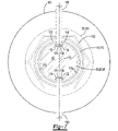
Figure 7 is a section view along section line 7-7 and additionally examples of engagement features fixing the preload nut to the drive pinion. -
Figure 8 is an exploded perspective view of the items shown inFigure 3 . - As required, detailed embodiments of the present invention are disclosed herein; however, it is to be understood that the disclosed embodiments are merely exemplary of the invention that may be embodied in various and alternative forms. The figures are not necessarily to scale; some features may be exaggerated or minimized to show details of particular components. Therefore, specific structural and functional details disclosed herein are not to be interpreted as limiting, but merely as a representative basis for teaching one skilled in the art to variously employ the present invention.
- Referring to
Figure 1 , an example of anaxle assembly 10 is shown. Theaxle assembly 10 may be provided with a motor vehicle like a truck, bus, farm equipment, mining equipment, military transport or weaponry vehicle, or cargo loading equipment for land, air, or marine vessels. The motor vehicle may include a trailer for transporting cargo in one or more embodiments. - The
axle assembly 10 may provide torque to one or more traction wheel assemblies that may include a tire mounted on a wheel. The wheel may be mounted to a wheel hub that may be rotatable about a wheel axis. - One or more axle assemblies may be provided with the vehicle. As is best shown with reference to
Figures 1 and2 , theaxle assembly 10 may include ahousing assembly 20, adifferential assembly 22, and at least oneaxle shaft 24. As is best shown inFigure 2 , theaxle assembly 10 may also include adrive pinion 26 and apreload nut 28. - Referring to
Figures 1 and2 , thehousing assembly 20 may receive various components of theaxle assembly 10. In addition, thehousing assembly 20 may facilitate mounting of theaxle assembly 10 to the vehicle. For instance, thehousing assembly 20 may include anaxle housing 30, adifferential carrier 32, and optionally anelectric motor housing 34 if an electric motor is provided with theaxle assembly 10. - Referring to
Figure 2 , theaxle housing 30 may at least partially receive thedifferential assembly 22. Optionally, theaxle housing 30 may receive and support theaxle shafts 24. - The
differential carrier 32 may be mounted to theaxle housing 30. Thedifferential carrier 32 may support thedifferential assembly 22. - The
differential assembly 22 may be at least partially received in thehousing assembly 20. Thedifferential assembly 22 may be rotatable about adifferential axis 40 and may transmit torque to theaxle shafts 24 and wheels. Thedifferential assembly 22 may be operatively connected to theaxle shafts 24 and may permit theaxle shafts 24 to rotate at different rotational speeds in a manner known by those skilled in the art. Thedifferential assembly 22 may have aring gear 42 that may have teeth the mate or mesh with the teeth of a gear of adrive pinion 26. Accordingly, thedifferential assembly 22 may receive torque from thedrive pinion 26 via thering gear 42 and transmit torque to theaxle shafts 24. - Referring to
Figures 1 and2 , theaxle shafts 24 may transmit torque from thedifferential assembly 22 to corresponding wheel hubs and wheels. Twoaxle shafts 24 may be provided such that eachaxle shaft 24 extends through a different arm portion of theaxle housing 30. Theaxle shafts 24 or a portion thereof may extend along and may be rotatable about an axis, such as thedifferential axis 40. Eachaxle shaft 24 may have a first end and a second end. The first end may be operatively connected to thedifferential assembly 22. The second end may be disposed opposite the first end and may be operatively connected to a wheel. Optionally, gear reduction may be provided between anaxle shaft 24 and a wheel. - Referring to
Figures 2 and8 , thedrive pinion 26 may transmit torque between a power source or torque source and thedifferential assembly 22 via thering gear 42. The power source may be of any suitable type. For instance, the power source may be an electrical power source or a non-electrical power source. An example of an electrical power source is an electrical machine like an electric motor. An example of a non-electrical power source is an internal combustion engine. In the configuration shown inFigure 2 , the power source is configured as an electric motor that is provided with theaxle assembly 10; however, it is contemplated that the power source, whether electrical or non-electrical, may not be provided with theaxle assembly 10. For instance, a power source may be located remotely from theaxle assembly 10 and may be operatively connected to theaxle assembly 10 via a linkage like a shaft. A power source that is configured as an electric motor may include astator 50 and arotor 52. In the configuration shown, thestator 50 is received inside thehousing assembly 20 while therotor 52 is received inside thestator 50. Therotor 52 may extend around and may be rotatable about an axis with respect to thestator 50. Therotor 52 may be operatively connected to thedrive pinion 26 in any suitable manner, such as via a transmission orgear reduction module 60. - Referring to
Figures 2 ,3 and8 , thedrive pinion 26 may be rotatable about anaxis 70, which may also be referred to as a drive pinion axis. Theaxis 70 may be disposed substantially perpendicular to thedifferential axis 40. In a configuration in which theaxle assembly 10 includes an electric motor, theaxis 70 may be the same as the axis about which therotor 52 may rotate or may differ from the axis about which therotor 52 may rotate. - The
drive pinion 26 may extend along or around theaxis 70. In at least one configuration, thedrive pinion 26 may include agear 80 and ashaft 82. - The
gear 80 may be disposed at or near an end of theshaft 82. Thegear 80 may have a plurality of teeth that may mate with corresponding teeth on thering gear 42. Thegear 80 may be integrally formed with theshaft 82 or may be provided as a separate component that may be fixedly disposed on theshaft 82. - The
shaft 82 may extend from thegear 80. For instance, theshaft 82 may extend from thegear 80 in a direction that extends away from thedifferential assembly 22. In at least one configuration such as is best shown with reference toFigures 3 and8 , theshaft 82 may include a firstouter surface 90, a secondouter surface 92, a thirdouter surface 94, a threadedportion 96, a recessouter surface 98, one ormore recesses 100, and aspline 102. Some of these features are optional as discussed below. - The first
outer surface 90 may extend from thegear 80 and may be an outside circumference of a portion of theshaft 82. A first drive pinion bearing 110 may be disposed on the firstouter surface 90 and may rotatably support thedrive pinion 26. The first drive pinion bearing 110 may have any suitable configuration. For instance, the first drive pinion bearing 110 may be configured as a roller bearing assembly that may include a plurality of rollingelements 112 that may be disposed between aninner race 114 and anouter race 116. Theinner race 114 may extend around and may be disposed on the firstouter surface 90. Theouter race 116 may extend around the rollingelements 112 and may be disposed on supporting component, such as thedifferential carrier 32. - The second
outer surface 92, if provided, may be positioned along theaxis 70 or axially positioned between the firstouter surface 90 and the thirdouter surface 94. The secondouter surface 92 may be an outside circumference of a portion of theshaft 82 and may have a smaller diameter than the firstouter surface 90. One ormore spacers 120 may be disposed on the secondouter surface 92. Thespacers 120 may be configured as rings that may encircle theshaft 82 and may be axially positioned between theinner races drive pinion bearings 110, 110' to inhibit axial movement of theinner races - The third
outer surface 94, if provided, may be axially positioned between the secondouter surface 92 and the threadedportion 96. The thirdouter surface 94 may be an outside circumference of a portion of theshaft 82 and may have a smaller diameter than the secondouter surface 92. A second drive pinion bearing 110' may be disposed on the thirdouter surface 94 and may rotatably support thedrive pinion 26. The second drive pinion bearing 110' may have any suitable configuration. For instance, the second drive pinion bearing 110' may be configured as a roller bearing assembly that may include a plurality of rollingelements 112' that may be disposed between aninner race 114' and an outer race 116'. Theinner race 114' may extend around and may be disposed on the thirdouter surface 94. The outer race 116' may extend around the rollingelements 112', may be disposed on a supporting component, such as thedifferential carrier 32. In at least one configuration, theinner race 114' of the second drive pinion bearing 110' may have a smaller inside diameter than theinner race 114 of the first drive pinion bearing 110, the outer race 116' of the second drive pinion bearing 110' may have a smaller outside diameter than theouter race 116 of the first drive pinion bearing 110, or both. - It is noted that the second
outer surface 92, the thirdouter surface 94, or both may be omitted. For instance, the axial length of the firstouter surface 90 may be increased and the second drive pinion bearing 110', thespacers 120, or both may be disposed on the firstouter surface 90. - Referring to
Figures 3 ,4 and8 , the threadedportion 96 may be axially positioned between the thirdouter surface 94 and thespline 102. The threadedportion 96 may facilitate installation of thepreload nut 28. For instance, the threadedportion 96 may include a thread that may mate or mesh with a corresponding thread on thepreload nut 28. In at least one configuration, the threadedportion 96 may have an outside diameter that may be smaller than the diameter of the firstouter surface 90, the secondouter surface 92, the thirdouter surface 94, or combinations thereof. - The recess
outer surface 98 may be axially positioned between thegear 80 and a distal end of theshaft 82 that may be disposed opposite thegear 80. For instance, the recessouter surface 98 may be axially positioned between the threadedportion 96 and thespline 102 and may extend between the threadedportion 96 and thespline 102. The recessouter surface 98 may be an outside circumference of a portion of theshaft 82 and may have a smaller diameter than the firstouter surface 90, the secondouter surface 92, thirdouter surface 94, the threadedportion 96, or combinations thereof. - One or
more recesses 100 may be provided with the recessouter surface 98. In the configuration shown, tworecesses 100 are illustrated; however, it is contemplated that a greater or lesser number ofrecesses 100 may be provided. Arecess 100 may be disposed proximate the threadedportion 96 and may be axially positioned further from thegear 80 than the threadedportion 96 is positioned from thegear 80. For instance, arecess 100 may be axially positioned between the threadedportion 96 and thespline 102. In at least one configuration, therecess 100 may extend past an end of thepreload nut 28 as is best shown inFigure 4 , in which case therecess 100 may be disposed closer to thespline 102 than thepreload nut 28 is disposed to thespline 102. - A
recess 100 may extend from the recessouter surface 98 toward theaxis 70 and may have any suitable configuration. For instance, arecess 100 may be configured as a blind hole or a through hole. In addition, arecess 100 may have any suitable shape. In the configuration shown, eachrecess 100 is depicted as being an elongated slot that has a generally oval-shaped configuration in which the length of therecess 100 in an axial direction is greater than its width in a circumferential direction. For example, the axial length of therecess 100 may be at least twice its width. It is also contemplated that arecess 100 may be provided with other shapes and may also have an axial length that is less than its width. For instance, arecess 100 may be configured as a groove that may extend continuously around theaxis 70. In at least one configuration, therecess 100 may be at least partially defined by arecess bottom surface 130, a firstlateral side 132, and a secondlateral side 134, which are best shown with reference toFigures 4 and5 . - The
recess bottom surface 130 may be disposed at a bottom of therecess 100. As such, therecess bottom surface 130 may be disposed closer to theaxis 70 than the recessouter surface 98. - The first
lateral side 132 may extend between the recessouter surface 98 and therecess bottom surface 130. For instance, the firstlateral side 132 may extend from the recessouter surface 98 to a first end or first edge of therecess bottom surface 130. - The second
lateral side 134 may be disposed opposite the firstlateral side 132. The secondlateral side 134 may extend between the recessouter surface 98 and therecess bottom surface 130. For instance, the secondlateral side 134 may extend from the recessouter surface 98 to a second end or second edge of therecess bottom surface 130. - Referring to
Figures 3 and8 , thespline 102, if provided, may be disposed between the threadedportion 96 and the distal end of theshaft 82. Thespline 102 may include a plurality of teeth. In at least one configuration, the teeth of thespline 102 may be disposed substantially parallel to theaxis 70 and may mate with a corresponding spline of another component, such as a coupling or shift collar that may operatively connect thedrive pinion 26 to the power source. Thespline 102 may have an outside diameter that may be larger than the diameter of the recessouter surface 98. It is also contemplated that thespline 102 may be omitted and that thedrive pinion 26 may be coupled to another component in a different manner, such as with a fastener, and that the recessouter surface 98 may be disposed proximate or may extend from an end of theshaft 82. - Referring to
Figures 4 and8 , thepreload nut 28 may be mountable to thedrive pinion 26. In at least one configuration, thepreload nut 28 may include afirst end 140, asecond end 142, ahole 144, athread 146, and adeformable ring 148. Thepreload nut 28 may optionally include aflange 150, atool engagement portion 152, atransition region 154, or combinations thereof. - The
first end 140 may face away from thegear 80 and the first and seconddrive pinion bearings 110, 110' when thepreload nut 28 is installed on thedrive pinion 26. - The
second end 142 may be disposed opposite thefirst end 140. Thesecond end 142 may face toward thegear 80 and the first and seconddrive pinion bearings 110, 110' when thepreload nut 28 is installed on thedrive pinion 26. For instance, thesecond end 142 may face toward and may engage or contact awasher 160 that may be axially positioned between the second drive pinion bearing 110' and thepreload nut 28. - The
hole 144 may be a through hole that may extend from thefirst end 140 to thesecond end 142. Theshaft 82 of thedrive pinion 26 may be received in and may extend through thehole 144. - The
thread 146 may be disposed in thehole 144. Thethread 146 may mate with the threadedportion 96 of thedrive pinion 26 to help secure thepreload nut 28 to thedrive pinion 26. In at least one configuration, thethread 146 may generally extend from thefirst end 140 toward thesecond end 142. Thethread 146 may not be provided with thedeformable ring 148. - The
deformable ring 148 may extend from thefirst end 140 toward thesecond end 142. For instance, thedeformable ring 148 may extend from thefirst end 140 to thethread 146. As such, thedeformable ring 148 may be disposed proximate thethread 146, the threadedportion 96, or both. In at least one configuration, thedeformable ring 148 may extend continuously around theaxis 70; however, it is contemplated that thedeformable ring 148 may be discontinuous. Thedeformable ring 148 may be deformable to engage theshaft 82 inside arecess 100 to inhibit rotation of thepreload nut 28 about theaxis 70 with respect to thedrive pinion 26 as will be discussed in more detail below. Thedeformable ring 148 may be at least partially defined by aninterior side 170 and anexterior side 172. - The
interior side 170 may face toward theshaft 82 of thedrive pinion 26. For example, theinterior side 170 may face toward the recessouter surface 98. At least a portion of theinterior side 170 may face toward and may overlap arecess 100. Theinterior side 170 may be spaced apart from the recessouter surface 98 prior to deformation or engagement with thedrive pinion 26 as will be discussed in more detail below. - The
exterior side 172 may be disposed opposite theinterior side 170. In at least one configuration, the wall thickness of thedeformable ring 148 in a radial direction from theinterior side 170 to theexterior side 172 may be less than the wall thickness of theflange 150, thetool engagement portion 152, thetransition region 154, or combinations thereof. - The
flange 150 may be disposed at thesecond end 142 and may extend from thesecond end 142 of thepreload nut 28. As such, theflange 150 may engage or contact thewasher 160 or theinner race 114' of the second drive pinion bearing 110' if thewasher 160 is omitted. Theflange 150 may extend further from theaxis 70 or may have a larger diameter than thetool engagement portion 152. - The
tool engagement portion 152 may be axially positioned between theflange 150 and thedeformable ring 148. For instance, thetool engagement portion 152 may extend from theflange 150 to thetransition region 154. In at least one configuration, thetool engagement portion 152 may include a plurality of intersecting flat surfaces that may be grasped by a tool, such as a wrench or socket, to facilitate tightening and loosening of thepreload nut 28. In at least one configuration, thetool engagement portion 152 may extend further from theaxis 70 than thedeformable ring 148 and thetransition region 154. - The
transition region 154 may extend axially between thetool engagement portion 152 and thedeformable ring 148. In at least one configuration, thetransition region 154 may be tapered such that the diameter of thetransition region 154 becomes progressively smaller in an axial direction that extends from thetool engagement portion 152 to thedeformable ring 148. As such, thetransition region 154 may extend further from theaxis 70 than thedeformable ring 148. - Referring to
Figures 2-7 , a method of assembly will now be discussed. - First, the
drive pinion 26, first and seconddrive pinion bearings 110, 110', andspacers 120 may be assembled, which may result in positioning of these components as is shown inFigures 2 and3 . Assembly of these components may occur in any appropriate sequence. For instance, the first drive pinion bearing 110, the second drive pinion bearing 110', or both may be installed on a supporting component, such as thedifferential carrier 32, prior to inserting thedrive pinion 26 into a drive pinion bearing. Alternatively, the first drive pinion bearing 110, second drive pinion bearing 110',spacers 120, or combinations thereof may be installed on theshaft 82 of thedrive pinion 26 before installation on the supporting component. As a nonlimiting example, the first drive pinion bearing 110 may be mounted to thedifferential carrier 32, theshaft 82 of thedrive pinion 26 may be inserted through the hole in theinner race 114 of the first drive pinion bearing 110, thespacers 120 may be slid onto theshaft 82, and then the second drive pinion bearing 110' may be slid onto theshaft 82 and into engagement with thedifferential carrier 32 such that thespacers 120 may be axially positioned between theinner race 114 of the first drive pinion bearing 110 and theinner race 114' of the second drive pinion bearing 110'. - Next, the
washer 160 may be slid onto theshaft 82 and into engagement with the second drive pinion bearing 110'. - Next, the
preload nut 28 may be installed on theshaft 82. Thepreload nut 28 may be installed by engaging or mating thethread 146 of thepreload nut 28 with the threadedportion 96 of thedrive pinion 26 and rotating thepreload nut 28 in a first rotational direction about theaxis 70. Thepreload nut 28 may be rotated to advance thepreload nut 28 in an axial direction toward thegear 80 and may be rotated and tightened until thepreload nut 28 exerts a desired preload force against the first drive pinion bearing 110, the second drive pinion bearing 110', or both. At this point, the positioning of thepreload nut 28 may resemble that shown inFigures 2-5 , with thedeformable ring 148 of thepreload nut 28 extending around at least a portion of therecess 100, disposed outside of therecess 100, and spaced apart from thedrive pinion 26. - Next, the
deformable ring 148 may be deformed into therecess 100 and into engagement with thedrive pinion 26 to inhibit thepreload nut 28 from rotating with respect to thedrive pinion 26. This is best shown with reference toFigures 6 and7 . For instance, a tool having one or more engagement features 180, which are shown inFigure 7 , may engage theexterior side 172 of thedeformable ring 148. Anengagement feature 180 may be actuated to exert a compressive force against theexterior side 172 of thedeformable ring 148 that may be sufficient to compress and form at least a portion of thedeformable ring 148 into therecess 100. Anengagement feature 180 may have any suitable configuration. For example, anengagement feature 180 may be configured as a punch or crimp head and may optionally have a tip that may be sized slightly smaller than therecess 100. In the configuration shown inFigure 7 , two engagement features 180 are illustrated that are disposed directly opposite each other and are aligned with correspondingrecesses 100 in thedrive pinion 26. The engagement features 180 may be actuated at the same time to compress thedeformable ring 148 into eachrecess 100. - Referring to
Figure 6 , a portion of thefirst end 140 of thepreload nut 28 may be received in therecess 100 after thedeformable ring 148 is deformed. Alternatively, thefirst end 140 of thepreload nut 28 may not be received in therecess 100 if thedeformable ring 148 has a sufficient axial length to extend past the end of therecess 100 that is disposed closest to thespline 102. In such a configuration, a portion of thedeformable ring 148 that is disposed between thefirst end 140 and thethread 146 may be deformed into therecess 100 by anengagement feature 180. - Referring to
Figures 6 and7 , thedeformable ring 148 may engage or contact various surfaces that may define therecess 100 after deformation. For instance, thedeformable ring 148 may engage or contact therecess bottom surface 130, the firstlateral side 132, the secondlateral side 134, or combinations thereof. Thedeformable ring 148 need not engage therecess bottom surface 130, both lateral sides, or the axial ends or left and right ends of therecess 100 from the perspective shown inFigure 6 . However, engaging thedeformable ring 148 with the firstlateral side 132 and the secondlateral side 134 may inhibit rotation of thepreload nut 28 in first and second rotational directions about theaxis 70 with respect to thedrive pinion 26 and thereby inhibit tightening or loosening of thepreload nut 28. - Referring to
Figure 7 , in a configuration havingmultiple recesses 100, theinterior side 170 of thedeformable ring 148 may be at least partially spaced apart from the recessouter surface 98 of theshaft 82 after thedeformable ring 148 has been compressed or deformed. For instance, theinterior side 170 may be at least partially spaced apart from the recessouter surface 98 betweenadjacent recesses 100, such as to the left and right of therecesses 100 from the perspective shown. It is also contemplated that theinterior side 170 may engage the recessouter surface 98 continuously around theaxis 70 once thedeformable ring 148 has been compressed or deformed. - The
engagement feature 180 may be disengaged from or retracted away from thedeformable ring 148 after thedeformable ring 148 has been deformed into therecess 100. - An axle assembly having a drive pinion and preload nut as described above may allow a preload nut to be installed and secured to prevent or inhibit rotation of the preload nut with respect to the drive pinion, which may allow a bearing preload force to be set and maintained. Maintaining a desired preload force may prevent skidding of a bearing assembly, reduce friction and heating of the bearing, and help improve bearing life, thereby reducing maintenance costs. Moreover, the preload nut may be installed without the use of additional locking devices or components, such as mechanical locking devices like nylon nuts, split washers, or adhesives like a thread locking fluid, which may help reduce costs and assembly time. Moreover, the deformable portion of the preload nut may be mechanically separable or disengageable from the drive pinion in the event that removal of the preload nut from the drive pinion is subsequently desired. For instance, the deformable portion of the preload nut that is received in a recess may be pushed out of the recess or severed from the preload nut to permit the preload nut to be easily unthreaded from the drive pinion without damaging the threads of the drive pinion, which may allow the drive pinion to be removed from the axle assembly and subsequently reused, thereby reducing costs.
- While exemplary embodiments are described above, it is not intended that these embodiments describe all possible forms of the invention. Rather, the words used in the specification are words of description rather than limitation, and it is understood that various changes may be made without departing from the spirit and scope of the invention. Additionally, the features of various implementing embodiments may be combined to form further embodiments of the invention.
Claims (15)
- An axle assembly comprising:a drive pinion that is rotatable about an axis, the drive pinion including:a gear; anda shaft that extends from the gear, the shaft having a threaded portion and a recess that is disposed proximate the threaded portion; anda preload nut that has a thread that mates with the threaded portion and a deformable ring that is disposed proximate the threaded portion, wherein the deformable ring engages the shaft inside the recess to inhibit the preload nut from rotating about the axis with respect to the drive pinion.
- The axle assembly of claim 1 wherein the recess is axially positioned further from the gear than the threaded portion is positioned from the gear.
- The axle assembly of claim 1 wherein the shaft includes a spline and the recess is axially positioned between the threaded portion and the spline, preferably the spline is disposed closer to the recess than to the preload nut.
- The axle assembly of claim 1 wherein the shaft has a spline and a recess outer surface that extends between the threaded portion and the spline, wherein the recess extends from the recess outer surface toward the axis, preferably the spline has an outside diameter that is larger than a diameter of the recess outer surface and the recess outer surface has a smaller diameter than the threaded portion.
- The axle assembly of claim 4 wherein the recess is at least partially defined by a recess bottom surface and a first lateral side that extends between the recess outer surface and the recess bottom surface, wherein the deformable ring engages the first lateral side, preferably the recess is at least partially defined by a second lateral side that is disposed opposite the first lateral side and extends between the recess outer surface and the recess bottom surface, wherein the deformable ring engages the second lateral side.
- The axle assembly of claim 1 wherein the preload nut has a first end from which the deformable ring extends and a portion of the first end is received in the recess.
- The axle assembly of claim 1 wherein the deformable ring extends continuously around the axis.
- The axle assembly of claim 1 wherein the shaft has a recess outer surface from which the recess extends, and the deformable ring has an interior side that faces toward the recess outer surface, wherein at least a portion of the interior side is spaced apart from the recess outer surface.
- The axle assembly of claim 1 wherein the shaft has a second recess that is spaced apart from the recess, and a recess outer surface from which the recess and the second recess extend toward the axis, and the deformable ring has an interior side that faces toward the recess outer surface, wherein the interior side is at least partially spaced apart from the recess outer surface between the recess and the second recess.
- The axle assembly of claim 1 wherein the deformable ring extends from a first end of the preload nut, a flange is disposed at a second end of the preload nut, and a tool engagement portion is axially positioned between the flange and the deformable ring, wherein the flange extends further from the axis than the tool engagement portion and the tool engagement portion extends further from the axis than the deformable ring, preferably the preload nut has a transition region that extends axially between the tool engagement portion and the deformable ring, wherein the tool engagement portion extends further from the axis than the transition region and the transition region extends further from the axis than the deformable ring.
- A method of assembling an axle assembly comprising:threading a preload nut onto a threaded portion of a drive pinion such that a deformable ring of the preload nut is disposed outside and extends around at least a portion of a recess in the drive pinion; anddeforming the deformable ring into the recess and into engagement with the drive pinion in the recess to inhibit the preload nut from rotating with respect to the drive pinion.
- The method of claim 11 wherein threading the preload nut onto the threaded portion of the drive pinion includes tightening the preload nut to exert a preload force on a roller bearing assembly that rotatably supports the drive pinion, and deforming the deformable ring secures the preload nut to maintain the preload force.
- The method of claim 11 wherein the deformable ring is spaced apart from the drive pinion before deforming and the deformable ring contacts the drive pinion in the recess after deforming.
- The method of claim 11 wherein the recess is at least partially defined by a recess bottom surface, a first lateral side that extends from the recess bottom surface, and a second lateral side that is disposed opposite the first lateral side and extends from the recess bottom surface, and deforming the deformable ring engages the deformable ring against the first lateral side and the second lateral side.
- The method of claim 11 wherein the deformable ring is deformed with a first engagement feature that compresses the deformable ring into the recess, preferably the deformable ring is deformed with a second engagement feature that compresses the deformable ring into a second recess in the drive pinion at the same time the first engagement feature compresses the deformable ring into the recess.
Applications Claiming Priority (1)
| Application Number | Priority Date | Filing Date | Title |
|---|---|---|---|
| US17/143,597 US11820171B2 (en) | 2021-01-07 | 2021-01-07 | Axle assembly having a drive pinion and a preload nut and a method of assembly |
Publications (1)
| Publication Number | Publication Date |
|---|---|
| EP4027038A1 true EP4027038A1 (en) | 2022-07-13 |
Family
ID=79230938
Family Applications (1)
| Application Number | Title | Priority Date | Filing Date |
|---|---|---|---|
| EP22150153.9A Pending EP4027038A1 (en) | 2021-01-07 | 2022-01-04 | Axle assembly having a drive pinion and a preload nut and a method of assembly |
Country Status (4)
| Country | Link |
|---|---|
| US (1) | US11820171B2 (en) |
| EP (1) | EP4027038A1 (en) |
| CN (1) | CN114714813B (en) |
| BR (1) | BR102022000086A2 (en) |
Families Citing this family (3)
| Publication number | Priority date | Publication date | Assignee | Title |
|---|---|---|---|---|
| EP4097369B1 (en) * | 2020-01-28 | 2024-02-07 | Sew-Eurodrive GmbH & Co. KG | Bearing assembly comprising a shaft, a first bearing and a nut |
| US12269337B2 (en) | 2023-01-25 | 2025-04-08 | Arvinmeritor Technology, Llc | Axle assembly having a drive pinion and a preload nut |
| US11994198B1 (en) | 2023-06-05 | 2024-05-28 | Arvinmeritor Technology, Llc | Axle assembly having a preload mechanism |
Citations (4)
| Publication number | Priority date | Publication date | Assignee | Title |
|---|---|---|---|---|
| GB881308A (en) * | 1958-03-10 | 1961-11-01 | Iwao Vozumi | Locking means for nuts and bolts |
| US20180126783A1 (en) * | 2013-03-15 | 2018-05-10 | Paul J. Valente | Axle Assembly |
| US10316950B2 (en) | 2017-03-10 | 2019-06-11 | Arvinmeritor Technology, Llc | Axle assembly having a drive pinion and a bearing preload element |
| CN211737963U (en) * | 2020-03-20 | 2020-10-23 | 三一汽车制造有限公司 | Transfer case and engineering machinery with same |
Family Cites Families (19)
| Publication number | Priority date | Publication date | Assignee | Title |
|---|---|---|---|---|
| US6532666B1 (en) * | 2001-11-29 | 2003-03-18 | The Timken Company | Process for capturing a bearing race on a spindle |
| US20070116397A1 (en) * | 2005-11-18 | 2007-05-24 | The Timken Company | Unitized bearing assembly and method of assembling the same |
| US7485065B2 (en) * | 2006-07-24 | 2009-02-03 | Ford Global Technologies, Llc | Producing and maintaining a desired bearing preload in a differential mechanism |
| US10065455B2 (en) * | 2015-11-03 | 2018-09-04 | Arvinmeritor Technology, Llc | Axle assembly having a wet disc brake |
| US10156289B2 (en) * | 2017-03-07 | 2018-12-18 | Meritor do Brasil Sistemas Automotivos Ltda. | Axle assembly having multiple clutch collars |
| US10208846B2 (en) | 2017-03-10 | 2019-02-19 | Arvinmeritor Technology, Llc | Axle assembly having a drive pinion support bearing and a method of assembly |
| US10500940B2 (en) | 2017-08-18 | 2019-12-10 | Arvinmeritor Technology, Llc | Axle assembly having an electric motor module and a gear reduction module |
| US11273700B2 (en) | 2017-08-18 | 2022-03-15 | Arvinmeritor Technology, Llc | Axle assembly having an electric motor module |
| US10500941B2 (en) | 2017-08-18 | 2019-12-10 | Arvinmeritor Technology, Llc | Axle assembly having an electric motor module and a shift mechanism |
| US10364872B2 (en) * | 2017-10-17 | 2019-07-30 | Arvinmeritor Technology, Llc | Axle assembly having a gear reduction unit and an interaxle differential unit |
| US10703202B2 (en) * | 2018-02-12 | 2020-07-07 | Arvinmeritor Technology, Llc | Drive axle assembly with clutch collar |
| US10808830B2 (en) | 2018-11-30 | 2020-10-20 | Arvinmeritor Technology, Llc | Axle assembly with multiple lubricant chambers |
| US10801602B2 (en) | 2018-11-30 | 2020-10-13 | Arvinmeritor Technology, Llc | Axle assembly having counterphase planet gears |
| US10704597B2 (en) | 2018-11-30 | 2020-07-07 | Arvinmeritor Technology, Llc | Axle assembly having a bearing preload module |
| US10808834B2 (en) | 2018-11-30 | 2020-10-20 | Arvinmeritor Technology, Llc | Axle assembly and method of control |
| US11038396B2 (en) | 2018-11-30 | 2021-06-15 | Arvinmeritor Technology, Llc | Axle assembly having an electric motor module and method of assembly |
| US10935120B2 (en) | 2018-11-30 | 2021-03-02 | Arvinmeritor Technology, Llc | Axle assembly having a spigot bearing assembly |
| US10985635B2 (en) | 2018-11-30 | 2021-04-20 | Arvinmeritor Technology, Llc | Axle assembly having a resolver and a method of assembly |
| US11124054B1 (en) * | 2020-10-06 | 2021-09-21 | Arvinmeritor Technology, Llc | Axle assembly having a sensor for detecting a shift collar |
-
2021
- 2021-01-07 US US17/143,597 patent/US11820171B2/en active Active
-
2022
- 2022-01-04 EP EP22150153.9A patent/EP4027038A1/en active Pending
- 2022-01-04 BR BR102022000086-7A patent/BR102022000086A2/en not_active Application Discontinuation
- 2022-01-06 CN CN202210009930.8A patent/CN114714813B/en active Active
Patent Citations (4)
| Publication number | Priority date | Publication date | Assignee | Title |
|---|---|---|---|---|
| GB881308A (en) * | 1958-03-10 | 1961-11-01 | Iwao Vozumi | Locking means for nuts and bolts |
| US20180126783A1 (en) * | 2013-03-15 | 2018-05-10 | Paul J. Valente | Axle Assembly |
| US10316950B2 (en) | 2017-03-10 | 2019-06-11 | Arvinmeritor Technology, Llc | Axle assembly having a drive pinion and a bearing preload element |
| CN211737963U (en) * | 2020-03-20 | 2020-10-23 | 三一汽车制造有限公司 | Transfer case and engineering machinery with same |
Also Published As
| Publication number | Publication date |
|---|---|
| CN114714813B (en) | 2025-01-24 |
| CN114714813A (en) | 2022-07-08 |
| US11820171B2 (en) | 2023-11-21 |
| US20220212498A1 (en) | 2022-07-07 |
| BR102022000086A2 (en) | 2022-07-12 |
Similar Documents
| Publication | Publication Date | Title |
|---|---|---|
| US11820171B2 (en) | Axle assembly having a drive pinion and a preload nut and a method of assembly | |
| US10208846B2 (en) | Axle assembly having a drive pinion support bearing and a method of assembly | |
| EP3427989B1 (en) | Axle assembly having a bearing preload bolt | |
| US9829048B2 (en) | Bearing device for wheel | |
| EP3275714B1 (en) | Axle assembly having a wheel mount disposed on a planet carrier | |
| EP3173649B1 (en) | Axle assembly having a wet disc brake | |
| US20160075179A1 (en) | Axle Assembly With Inboard Axle Shaft Bearings That Support A Differential Mechanism | |
| EP3165393B1 (en) | Axle assembly having a sun gear positioning arrangement | |
| US6659651B1 (en) | Driving and locking mechanism for a threaded bearing cup | |
| JP2014503776A (en) | Direct-drive drive module for differential gears for electric vehicles | |
| WO2014074507A1 (en) | Axle assembly | |
| US9927021B1 (en) | Planet carrier for a planetary gear set | |
| EP3267073A1 (en) | Axle assembly having a support bearing assembly | |
| CN210549404U (en) | Automobile semi-axis nut tightening device | |
| EP4474664A1 (en) | Axle assembly having a preload mechanism | |
| EP4407212A1 (en) | Axle assembly having a drive pinion and a preload nut | |
| US10941846B2 (en) | Differential assembly having an overhanging ring gear | |
| JP5250942B2 (en) | Rolling bearing device for wheels | |
| US9695923B2 (en) | Power transmitting component with pinion flange fixed to pinion | |
| EP4332402B1 (en) | Axle assembly and a unitary yoke-shaft | |
| EP4309940A1 (en) | Axle assembly having a wheel end assembly and a gear reduction unit | |
| WO2026053673A1 (en) | Hub assembly | |
| JPH04107545U (en) | planetary gear mechanism |
Legal Events
| Date | Code | Title | Description |
|---|---|---|---|
| PUAI | Public reference made under article 153(3) epc to a published international application that has entered the european phase |
Free format text: ORIGINAL CODE: 0009012 |
|
| STAA | Information on the status of an ep patent application or granted ep patent |
Free format text: STATUS: THE APPLICATION HAS BEEN PUBLISHED |
|
| AK | Designated contracting states |
Kind code of ref document: A1 Designated state(s): AL AT BE BG CH CY CZ DE DK EE ES FI FR GB GR HR HU IE IS IT LI LT LU LV MC MK MT NL NO PL PT RO RS SE SI SK SM TR |
|
| STAA | Information on the status of an ep patent application or granted ep patent |
Free format text: STATUS: REQUEST FOR EXAMINATION WAS MADE |
|
| 17P | Request for examination filed |
Effective date: 20230113 |
|
| RBV | Designated contracting states (corrected) |
Designated state(s): AL AT BE BG CH CY CZ DE DK EE ES FI FR GB GR HR HU IE IS IT LI LT LU LV MC MK MT NL NO PL PT RO RS SE SI SK SM TR |
|
| P01 | Opt-out of the competence of the unified patent court (upc) registered |
Effective date: 20230531 |
|
| STAA | Information on the status of an ep patent application or granted ep patent |
Free format text: STATUS: EXAMINATION IS IN PROGRESS |
|
| 17Q | First examination report despatched |
Effective date: 20240226 |