EP4407212A1 - Axle assembly having a drive pinion and a preload nut - Google Patents
Axle assembly having a drive pinion and a preload nut Download PDFInfo
- Publication number
- EP4407212A1 EP4407212A1 EP24153777.8A EP24153777A EP4407212A1 EP 4407212 A1 EP4407212 A1 EP 4407212A1 EP 24153777 A EP24153777 A EP 24153777A EP 4407212 A1 EP4407212 A1 EP 4407212A1
- Authority
- EP
- European Patent Office
- Prior art keywords
- yoke
- axis
- shaft
- assembly
- preload nut
- Prior art date
- Legal status (The legal status is an assumption and is not a legal conclusion. Google has not performed a legal analysis and makes no representation as to the accuracy of the status listed.)
- Pending
Links
- 230000036316 preload Effects 0.000 title claims abstract description 107
- 230000001419 dependent effect Effects 0.000 claims 1
- 230000000712 assembly Effects 0.000 description 14
- 238000000429 assembly Methods 0.000 description 14
- 238000009434 installation Methods 0.000 description 6
- 125000006850 spacer group Chemical group 0.000 description 4
- 238000005096 rolling process Methods 0.000 description 3
- 238000007789 sealing Methods 0.000 description 3
- 238000009987 spinning Methods 0.000 description 2
- 230000004323 axial length Effects 0.000 description 1
- 238000002485 combustion reaction Methods 0.000 description 1
- 239000000356 contaminant Substances 0.000 description 1
- 230000008878 coupling Effects 0.000 description 1
- 238000010168 coupling process Methods 0.000 description 1
- 238000005859 coupling reaction Methods 0.000 description 1
- 238000007373 indentation Methods 0.000 description 1
- 238000000034 method Methods 0.000 description 1
- 238000005065 mining Methods 0.000 description 1
- 238000012986 modification Methods 0.000 description 1
- 230000004048 modification Effects 0.000 description 1
Images


Classifications
-
- B—PERFORMING OPERATIONS; TRANSPORTING
- B60—VEHICLES IN GENERAL
- B60K—ARRANGEMENT OR MOUNTING OF PROPULSION UNITS OR OF TRANSMISSIONS IN VEHICLES; ARRANGEMENT OR MOUNTING OF PLURAL DIVERSE PRIME-MOVERS IN VEHICLES; AUXILIARY DRIVES FOR VEHICLES; INSTRUMENTATION OR DASHBOARDS FOR VEHICLES; ARRANGEMENTS IN CONNECTION WITH COOLING, AIR INTAKE, GAS EXHAUST OR FUEL SUPPLY OF PROPULSION UNITS IN VEHICLES
- B60K17/00—Arrangement or mounting of transmissions in vehicles
- B60K17/04—Arrangement or mounting of transmissions in vehicles characterised by arrangement, location, or kind of gearing
- B60K17/16—Arrangement or mounting of transmissions in vehicles characterised by arrangement, location, or kind of gearing of differential gearing
-
- B—PERFORMING OPERATIONS; TRANSPORTING
- B60—VEHICLES IN GENERAL
- B60K—ARRANGEMENT OR MOUNTING OF PROPULSION UNITS OR OF TRANSMISSIONS IN VEHICLES; ARRANGEMENT OR MOUNTING OF PLURAL DIVERSE PRIME-MOVERS IN VEHICLES; AUXILIARY DRIVES FOR VEHICLES; INSTRUMENTATION OR DASHBOARDS FOR VEHICLES; ARRANGEMENTS IN CONNECTION WITH COOLING, AIR INTAKE, GAS EXHAUST OR FUEL SUPPLY OF PROPULSION UNITS IN VEHICLES
- B60K17/00—Arrangement or mounting of transmissions in vehicles
- B60K17/22—Arrangement or mounting of transmissions in vehicles characterised by arrangement, location, or type of main drive shafting, e.g. cardan shaft
- B60K17/24—Arrangements of mountings for shafting
-
- F—MECHANICAL ENGINEERING; LIGHTING; HEATING; WEAPONS; BLASTING
- F16—ENGINEERING ELEMENTS AND UNITS; GENERAL MEASURES FOR PRODUCING AND MAINTAINING EFFECTIVE FUNCTIONING OF MACHINES OR INSTALLATIONS; THERMAL INSULATION IN GENERAL
- F16C—SHAFTS; FLEXIBLE SHAFTS; ELEMENTS OR CRANKSHAFT MECHANISMS; ROTARY BODIES OTHER THAN GEARING ELEMENTS; BEARINGS
- F16C19/00—Bearings with rolling contact, for exclusively rotary movement
- F16C19/54—Systems consisting of a plurality of bearings with rolling friction
- F16C19/546—Systems with spaced apart rolling bearings including at least one angular contact bearing
- F16C19/547—Systems with spaced apart rolling bearings including at least one angular contact bearing with two angular contact rolling bearings
- F16C19/548—Systems with spaced apart rolling bearings including at least one angular contact bearing with two angular contact rolling bearings in O-arrangement
-
- F—MECHANICAL ENGINEERING; LIGHTING; HEATING; WEAPONS; BLASTING
- F16—ENGINEERING ELEMENTS AND UNITS; GENERAL MEASURES FOR PRODUCING AND MAINTAINING EFFECTIVE FUNCTIONING OF MACHINES OR INSTALLATIONS; THERMAL INSULATION IN GENERAL
- F16C—SHAFTS; FLEXIBLE SHAFTS; ELEMENTS OR CRANKSHAFT MECHANISMS; ROTARY BODIES OTHER THAN GEARING ELEMENTS; BEARINGS
- F16C25/00—Bearings for exclusively rotary movement adjustable for wear or play
- F16C25/06—Ball or roller bearings
-
- F—MECHANICAL ENGINEERING; LIGHTING; HEATING; WEAPONS; BLASTING
- F16—ENGINEERING ELEMENTS AND UNITS; GENERAL MEASURES FOR PRODUCING AND MAINTAINING EFFECTIVE FUNCTIONING OF MACHINES OR INSTALLATIONS; THERMAL INSULATION IN GENERAL
- F16H—GEARING
- F16H48/00—Differential gearings
- F16H48/12—Differential gearings without gears having orbital motion
-
- F—MECHANICAL ENGINEERING; LIGHTING; HEATING; WEAPONS; BLASTING
- F16—ENGINEERING ELEMENTS AND UNITS; GENERAL MEASURES FOR PRODUCING AND MAINTAINING EFFECTIVE FUNCTIONING OF MACHINES OR INSTALLATIONS; THERMAL INSULATION IN GENERAL
- F16H—GEARING
- F16H48/00—Differential gearings
- F16H48/38—Constructional details
- F16H48/42—Constructional details characterised by features of the input shafts, e.g. mounting of drive gears thereon
-
- F—MECHANICAL ENGINEERING; LIGHTING; HEATING; WEAPONS; BLASTING
- F16—ENGINEERING ELEMENTS AND UNITS; GENERAL MEASURES FOR PRODUCING AND MAINTAINING EFFECTIVE FUNCTIONING OF MACHINES OR INSTALLATIONS; THERMAL INSULATION IN GENERAL
- F16H—GEARING
- F16H57/00—General details of gearing
- F16H57/02—Gearboxes; Mounting gearing therein
- F16H57/021—Shaft support structures, e.g. partition walls, bearing eyes, casing walls or covers with bearings
- F16H57/022—Adjustment of gear shafts or bearings
-
- F—MECHANICAL ENGINEERING; LIGHTING; HEATING; WEAPONS; BLASTING
- F16—ENGINEERING ELEMENTS AND UNITS; GENERAL MEASURES FOR PRODUCING AND MAINTAINING EFFECTIVE FUNCTIONING OF MACHINES OR INSTALLATIONS; THERMAL INSULATION IN GENERAL
- F16H—GEARING
- F16H57/00—General details of gearing
- F16H57/02—Gearboxes; Mounting gearing therein
- F16H57/023—Mounting or installation of gears or shafts in the gearboxes, e.g. methods or means for assembly
-
- F—MECHANICAL ENGINEERING; LIGHTING; HEATING; WEAPONS; BLASTING
- F16—ENGINEERING ELEMENTS AND UNITS; GENERAL MEASURES FOR PRODUCING AND MAINTAINING EFFECTIVE FUNCTIONING OF MACHINES OR INSTALLATIONS; THERMAL INSULATION IN GENERAL
- F16H—GEARING
- F16H57/00—General details of gearing
- F16H57/02—Gearboxes; Mounting gearing therein
- F16H57/029—Gearboxes; Mounting gearing therein characterised by means for sealing the gearboxes, e.g. to improve airtightness
-
- F—MECHANICAL ENGINEERING; LIGHTING; HEATING; WEAPONS; BLASTING
- F16—ENGINEERING ELEMENTS AND UNITS; GENERAL MEASURES FOR PRODUCING AND MAINTAINING EFFECTIVE FUNCTIONING OF MACHINES OR INSTALLATIONS; THERMAL INSULATION IN GENERAL
- F16H—GEARING
- F16H57/00—General details of gearing
- F16H57/02—Gearboxes; Mounting gearing therein
- F16H57/037—Gearboxes for accommodating differential gearings
-
- F—MECHANICAL ENGINEERING; LIGHTING; HEATING; WEAPONS; BLASTING
- F16—ENGINEERING ELEMENTS AND UNITS; GENERAL MEASURES FOR PRODUCING AND MAINTAINING EFFECTIVE FUNCTIONING OF MACHINES OR INSTALLATIONS; THERMAL INSULATION IN GENERAL
- F16H—GEARING
- F16H48/00—Differential gearings
- F16H48/38—Constructional details
- F16H48/42—Constructional details characterised by features of the input shafts, e.g. mounting of drive gears thereon
- F16H2048/423—Constructional details characterised by features of the input shafts, e.g. mounting of drive gears thereon characterised by bearing arrangement
-
- F—MECHANICAL ENGINEERING; LIGHTING; HEATING; WEAPONS; BLASTING
- F16—ENGINEERING ELEMENTS AND UNITS; GENERAL MEASURES FOR PRODUCING AND MAINTAINING EFFECTIVE FUNCTIONING OF MACHINES OR INSTALLATIONS; THERMAL INSULATION IN GENERAL
- F16H—GEARING
- F16H57/00—General details of gearing
- F16H57/02—Gearboxes; Mounting gearing therein
- F16H57/021—Shaft support structures, e.g. partition walls, bearing eyes, casing walls or covers with bearings
- F16H57/022—Adjustment of gear shafts or bearings
- F16H2057/0221—Axial adjustment
Definitions
- This relates to an axle assembly that has a drive pinion and a preload nut and a method of assembly.
- an axle assembly in at least one embodiment, includes a differential carrier, a drive pinion, a bearing assembly, a preload nut, and a seal assembly.
- the drive pinion is rotatable about an axis.
- the drive pinion includes a gear and a shaft that extends from the gear.
- the shaft has a threaded portion.
- the bearing assembly encircles the shaft and rotatably supports the drive pinion on the differential carrier.
- the preload nut has a thread that mates with the threaded portion of the shaft.
- the preload nut engages the bearing assembly and exerts a preload force on the bearing assembly.
- the seal assembly encircles the preload nut.
- the seal assembly extends from the preload nut to the differential carrier.
- the preload nut may have an external circumferential surface.
- the external circumferential surface may encircle the axis.
- the external circumferential surface may face away from the axis.
- the seal assembly may engage the external circumferential surface.
- the shaft may include an outer surface.
- the shaft may include a spline.
- the threaded portion may be axially positioned between the outer surface and the spline.
- the axle assembly may include a yoke.
- the yoke may be mounted to the shaft.
- the yoke may encircle the shaft.
- the yoke may inhibit rotation of the preload nut.
- the bearing assembly may have an inner race.
- the preload nut may extend axially from the inner race to the yoke.
- the seal assembly may encircle and engage the preload nut.
- the seal assembly may encircle and engage the yoke.
- the preload nut may have an end surface.
- the end surface may engage the yoke.
- the preload nut may have one or more blind holes.
- a blind hole may extend from the end surface toward the bearing assembly.
- the deflector may extend from the yoke.
- the deflector may encircle a portion of the differential carrier.
- the yoke may have a yoke end surface.
- the yoke end surface may engage the preload nut.
- the yoke may have a first outer yoke surface.
- the first outer yoke surface may face away from the axis.
- the first outer yoke surface may extend from the yoke end surface.
- the seal assembly may engage the first outer yoke surface.
- the yoke may have a second yoke outer surface.
- the second yoke outer surface may face away from the axis.
- the second yoke outer surface may be disposed further from the axis than the first outer yoke surface is disposed from the axis.
- the deflector may engage the second yoke outer surface.
- the first outer yoke surface may be disposed closer to the axis than the external circumferential surface of the preload nut is disposed to the axis.
- the first outer yoke surface may be disposed closer to the axis than the second yoke outer surface is disposed to the axis.
- the seal assembly may have an inner member.
- the inner member may extend from the differential carrier to the external circumferential surface of the preload nut.
- the seal assembly may have an outer member.
- the outer member may extend from the first yoke outer surface toward the differential carrier.
- the outer member may be encircled by the differential carrier.
- the outer member may be encircled by the inner member.
- an axle assembly in at least one configuration, includes a differential carrier, a drive pinion, a bearing assembly, a preload nut, and a seal assembly.
- the drive pinion is rotatable about an axis.
- the drive pinion includes a gear and a shaft that extends from the gear.
- the shaft has a threaded portion.
- the bearing assembly encircles the shaft and rotatably supports the drive pinion on the differential carrier.
- the preload nut has a thread. The threat mates with the threaded portion of the shaft.
- the preload nut engages the bearing assembly and exerts a preload force on the bearing assembly.
- the seal assembly encircles the shaft.
- the seal assembly extends from the shaft to the differential carrier.
- the seal assembly may be spaced apart from the preload nut.
- the seal assembly may be axially positioned between the preload nut and the yoke.
- the shaft may have a spline.
- the spline may engage the yoke.
- the shaft may have a journal surface.
- the journal surface may face away from the axis.
- the journal surface may be axially positioned between the threaded portion and the spline of the shaft.
- the seal assembly may engage the journal surface.
- the journal surface may be positioned closer to the axis than the threaded portion is positioned to the axis.
- the journal surface may be positioned further from the axis than the spline is positioned from the axis.
- the seal assembly may have an inner member.
- the inner member may extend from the differential carrier to the journal surface.
- the inner member may be spaced apart from the preload nut.
- the inner member may be spaced apart from the yoke.
- the seal assembly may have an outer member.
- the outer member may extend from the yoke.
- the outer member may engage the inner member.
- the outer member may encircle the differential carrier.
- the outer member may encircle the inner member.
- the axle assembly may include first and second retaining features.
- the first and second retaining features may be separate from the shaft.
- the first and second retaining features may be mounted to the shaft.
- the first retaining feature may engage the yoke to inhibit movement of the yoke away from the preload nut.
- the second retaining feature may engage the yoke to inhibit movement of the yoke toward the preload nut.
- the first retaining feature may be received in a first groove of the shaft.
- the second retaining feature may be received in a second groove of the shaft.
- the yoke may encircle the second retaining feature.
- first, second, etc. are, in some instances, used herein to describe various elements, these elements should not be limited by these terms. These terms are only used to distinguish one element from another. For example, a first element could be termed a second element, and similarly a second element could be termed a first element without departing from the scope of the various described embodiments. The first element and the second element are both elements, but they are not the same element.
- the axle assembly 10 may be provided with a motor vehicle like a truck, bus, farm equipment, mining equipment, military transport or weaponry vehicle, or cargo loading equipment for land, air, or marine vessels.
- the motor vehicle may include a trailer for transporting cargo in one or more embodiments.
- the axle assembly 10 is configured to provide torque to one or more traction wheel assemblies that may include a tire mounted on a wheel.
- the wheel may be mounted to a wheel hub that may be rotatable about a wheel axis.
- axle assembly 10 may be provided with the vehicle.
- a single axle assembly 10 is shown.
- the axle assembly 10 may include a housing assembly 20, a differential assembly 22, and at least one axle shaft 24.
- the axle assembly 10 includes a drive pinion 26, at least one bearing assembly 28, 28', a preload nut 30, and a seal assembly 32.
- the axle assembly 10 may also include a yoke 34.
- the housing assembly 20 receives various components of the axle assembly 10.
- the housing assembly 20 may facilitate mounting of the axle assembly 10 to the vehicle.
- the housing assembly 20 may include an axle housing 40 and a differential carrier 42.
- one or more additional housings may be provided with the housing assembly 20, such as an electric motor housing if an electric motor is provided with the axle assembly 10.
- the axle housing 40 at least partially receives the differential assembly 22.
- the axle housing 40 may also have arm portions that receive and support the axle shafts 24.
- the differential carrier 42 is removably mountable to the axle housing 40.
- the differential carrier 42 supports the differential assembly 22.
- the differential carrier 42 may include bearing supports upon which bearing assemblies are disposed that rotatably support the differential assembly 22.
- the differential carrier 42 may also include a cavity 44 through which the drive pinion 26 may extend.
- the differential assembly 22 is receivable inside the housing assembly 20.
- the differential assembly 22 may be rotatable about a differential axis 50 and may transmit torque to the axle shafts 24 and wheels.
- the differential assembly 22 may be operatively connected to the axle shafts 24 and may permit the axle shafts 24 to rotate at different rotational speeds in a manner known by those skilled in the art.
- the differential assembly 22 may have a ring gear 52 that may have teeth the mate or mesh with the teeth of a gear of the drive pinion 26. Accordingly, the differential assembly 22 may receive torque from the drive pinion 26 via the ring gear 52 and transmit torque to the axle shafts 24.
- axle shafts 24 transmit torque between the differential assembly 22 and corresponding wheel hubs and wheels.
- Two axle shafts 24 may be provided such that each axle shaft 24 extends through a different arm portion of the axle housing 40.
- the axle shafts 24 or a portion thereof may extend along and may be rotatable about an axis, such as the differential axis 50 or an axis that differs from the differential axis 50.
- Each axle shaft 24 may have a first end and a second end. The first end may be operatively connected to the differential assembly 22. The second end may be disposed opposite the first end and may be operatively connected to a wheel, such as via a wheel hub.
- gear reduction may be provided between an axle shaft 24 and a wheel.
- the drive pinion 26 is configured to transmit torque between a power source or torque source and the differential assembly 22 via the ring gear 52.
- the power source may be of any suitable type.
- the power source may be an electrical power source or a non-electrical power source.
- An example of an electrical power source is an electrical machine like an electric motor.
- An example of a non-electrical power source is an internal combustion engine.
- the power source is configured to be located remotely from the axle assembly 10 and may be operatively connected to the axle assembly 10 via a linkage like a shaft; however, it is contemplated that the power source, whether electrical or non-electrical, may be provided with the axle assembly 10.
- the drive pinion 26 is rotatable about an axis 60.
- the axis 60 may be disposed substantially perpendicular to the differential axis 50.
- the drive pinion 26 may also extend along or around the axis 60.
- the drive pinion 26 includes a gear 70 and a shaft 72.
- the gear 70 may be disposed at or near an end of the shaft 72.
- the gear 70 may have a plurality of teeth that may mate with corresponding teeth on the ring gear 52.
- the teeth of the ring gear 52 and the gear 70 are simplified or not shown in the figures, but it is to be understood that the teeth of the gear 70 may have any suitable configuration that is compatible with the teeth of the ring gear 52, including but not limited to spiral teeth, hypoid teeth, etc., as is known by those skilled in the art.
- the gear 70 may be integrally formed with the shaft 72 or may be provided as a separate component that may be fixedly disposed on the shaft 72.
- the shaft 72 may extend from the gear 70.
- the shaft 72 may extend from the gear 70 in a direction that extends away from the differential assembly 22.
- the shaft 72 may include at least one outer surface, such as a first outer surface 80 and/or a second outer surface 82, a threaded portion 84, and a spline 86.
- the shaft 72 may also include a fastener hole 88.
- the first outer surface 80 may extend from the gear 70 and may be an outside circumference of a portion of the shaft 72. As such, the first outer surface 80 may face away from the axis 60.
- One or more bearing assemblies 28 that may be disposed in the cavity 44 of the differential carrier 42 may be disposed on the first outer surface 80 and may rotatably support the drive pinion 26.
- the bearing assemblies 28 may have any suitable configuration.
- a bearing assembly 28 may be configured as a roller bearing assembly that may encircle the shaft 72 and that may include a plurality of rolling elements 90 that may be disposed between an inner race 92 and an outer race 94.
- the inner race 92 may extend around and may be disposed on the first outer surface 80.
- the outer race 94 may extend around the rolling elements 90 and may be disposed on or contact a supporting component, such as the differential carrier 42.
- first bearing assembly 28 two bearing assemblies are provided and may be referred to as a first bearing assembly 28 and a second bearing assembly 28' for clarity.
- the second bearing assembly 28' and its components are designated with the same reference numbers as the first bearing assembly 28 but include a prime symbol after the number.
- the second bearing assembly 28' includes rolling elements 90', an inner race 92', and an outer race 94' that are analogous to the corresponding components of the first bearing assembly 28.
- the second outer surface 82 may be axially positioned or positioned along the axis 60 between the first outer surface 80 and the threaded portion 84.
- the second outer surface 82 may be an outside circumference of a portion of the shaft 72. As such, the second outer surface 82 may face away from the axis 60.
- the second outer surface 82 may have a smaller diameter than the first outer surface 80.
- One or more spacers 100 may be disposed on the second outer surface 82.
- the spacers 100 may be configured as rings that may encircle the shaft 72 and may be axially positioned between the inner races 92, 92' of the bearing assemblies 28, 28' to inhibit axial movement of the inner races 92, 92' toward each other.
- the spacers 100 may also transmit preload force between the bearing assemblies 28, 28'.
- the second bearing assembly 28' may also be disposed on the second outer surface 82.
- the second outer surface 82 may be omitted.
- the axial length of the first outer surface 80 may be increased and the second bearing assembly 28', the spacers 100, or both may be disposed on the first outer surface 80.
- additional outer surfaces may be provided.
- the second bearing assembly 28' may be disposed on a third outer surface that may extend between the second outer surface 82 and the threaded portion 84.
- the threaded portion 84 facilitates installation of the preload nut 30.
- the threaded portion 84 may be axially positioned or positioned along the axis 60 between an outer surface and the spline 86.
- the threaded portion 84 may be axially positioned between the second outer surface 82 and the spline 86.
- the threaded portion 84 may include a thread that may spiral around the axis 60 and mate or mesh with a corresponding thread on the preload nut 30.
- the threaded portion 84 may have an outside diameter that may be smaller than the diameter of the first outer surface 80, the second outer surface 82, or combinations thereof.
- the spline 86 may be disposed between the threaded portion 84 and a distal end of the shaft 72.
- the spline 86 may include a plurality of teeth.
- the teeth of the spline 86 may be disposed substantially parallel to the axis 60 and may mate with a corresponding spline of another component, such as the yoke 34, that may operatively connect the drive pinion 26 to the power source.
- the spline 86 may have an outside diameter that may be less than the diameter of the outside diameter of the threaded portion 84. It is also contemplated that the spline 86 may be omitted.
- the fastener hole 88 may extend from a distal end of the shaft 72 toward the gear 70.
- the fastener hole 88 may be disposed along the axis 60.
- the fastener hole 88 may be a threaded hole and may be configured to receive a fastener 170, such as a bolt.
- the preload nut 30 is mountable to the drive pinion 26 and engageable with a bearing assembly.
- the preload nut 30 is configured to exert a preload force on the one or more bearing assemblies 28, 28' that rotatably support the drive pinion 26 on the differential carrier 42.
- the preload nut 30 may include a first end 110, a second end 112, a hole 114, and a thread 116.
- the preload nut 30 includes an external circumferential surface 118 and one or more apertures 120.
- the first end 110 which may also be referred to as a first end surface, may face away from the gear 70 and away from the first and second bearing assemblies 28, 28' when the preload nut 30 is installed on the drive pinion 26.
- the first end 110 may face toward and may engage or contact the yoke 34.
- the second end 112 which may also be referred to as a second end surface, may be disposed opposite the first end 110.
- the second end 112 may face toward the gear 70 and the first and second bearing assemblies 28, 28' when the preload nut 30 is installed on the drive pinion 26.
- the second end 112 may face toward and may engage or contact the inner race 92' of the second bearing assembly 28'.
- the hole 114 may be a through hole that may extend from the first end 110 to the second end 112.
- the shaft 72 of the drive pinion 26 may be received in and may extend through the hole 114.
- the thread 116 is disposed in the hole 114.
- the thread 116 may mate with the threaded portion 84 of the drive pinion 26 to help secure the preload nut 30 to the drive pinion 26.
- the thread 116 may generally extend from the first end 110 toward or to the second end 112.
- the external circumferential surface 118 encircles and faces away from the axis 60.
- the external circumferential surface 118 may extend between the first end 110 and the second end 112. In the configuration shown, the external circumferential surface 118 extends from the first end 110 to the second end 112.
- the external circumferential surface may be a smooth surface that may be radially disposed with respect to the axis 60.
- One or more apertures 120 may be provided in the preload nut 30.
- the apertures 120 may receive a tool that may rotate the preload nut 30 to tighten or loosen the preload nut 30 to provide a desired bearing preload force.
- the apertures 120 may be blind holes or through holes. In the configuration shown, the apertures 120 are configured as blind holes and extend from the first end 110 toward the second end 112.
- the seal assembly 32 is configured to seal an opening of the differential carrier 42 and provide a seal between the differential carrier 42 and the drive pinion 26 or between the differential carrier 42 and one or more components that are disposed on the drive pinion 26.
- the seal assembly 32 encircles the preload nut 30 and extends from differential carrier 42 to the preload nut 30.
- the seal assembly 32 may engage or contact the external circumferential surface 118 of the preload nut 30.
- the seal assembly 32 may also encircle and extend to the yoke 34.
- the seal assembly 32 may include an inner member 140 and an outer member 142.
- a deflector 144 may also be provided.
- the inner member 140 may extend from the differential carrier 42 to the preload nut 30.
- the inner member 140 may extend from an internal surface of the differential carrier 42 that faces toward the axis 60 and/or from an end surface of the differential carrier 42 that defines or encircles an opening of the cavity 44 to the external circumferential surface 118 of the preload nut 30.
- the inner member 140 may be fixedly disposed on the differential carrier 42.
- the drive pinion 26, preload nut 30, and yoke 34 may be rotatable together about the axis 60 with respect to the inner member 140.
- the outer member 142 may extend from the yoke 34 toward the differential carrier 42.
- the outer member 142 may extend from a first yoke outer surface 158 of the yoke 34 toward the differential carrier 42 such that at least a portion of the outer member 142 is encircled by the differential carrier 42 and the inner member 140.
- the outer member 142 may be rotatable about the axis 60 with the yoke 34 and may be rotatable about the axis 60 with respect to the inner member 140.
- the outer member 142 may be axially positioned further outboard or further away from the preload nut 30 than the inner member 140.
- the deflector 144 helps cover or conceal the seal assembly 32 and the opening of the differential carrier 42 in which the seal assembly 32 is received. As such, the deflector 144 may help block or prevent some contaminants from reaching the seal assembly 32.
- the deflector 144 may be fixedly disposed on the yoke 34 and may extend away from the axis 60 and around the end surface of the differential carrier 42.
- the deflector 144 may be spaced apart from the differential carrier 42 so that the deflector 144 may rotate about the axis 60 with the drive pinion 26 and the yoke 34 and with respect to the differential carrier 42.
- the deflector 144 may encircle a portion of the differential carrier 42, the inner member 140, the outer member 142, or combinations thereof.
- the yoke 34 is configured to facilitate coupling of the drive pinion 26 to the power source or to another axle assembly.
- the yoke 34 may be coupled to another component, such as a universal joint, which in turn may be coupled to a torque transmitting component like a drive shaft or a prop shaft.
- the yoke 34 may be stationarily mounted to the drive pinion 26.
- the yoke 34 includes a first yoke end surface 150, a second yoke end surface 152, a yoke hole 154, a yoke spline 156, a first yoke outer surface 158, a second yoke outer surface 160, or combinations thereof.
- the first yoke end surface 150 may face away from the gear 70 and the preload nut 30 when the yoke 34 is installed on the drive pinion 26.
- a fastener 170 such as a bolt or bolt and washer, may be provided to inhibit axial movement of the yoke 34 or movement along the axis 60 with respect to the shaft 72 of the drive pinion 26.
- the fastener 170 may be threaded into the fastener hole 88 in the shaft 72 may engage the first yoke end surface 150.
- the second yoke end surface 152 may be disposed opposite the first yoke end surface 150.
- the second yoke end surface 152 may face toward the gear 70.
- the second yoke end surface 152 may engage or contact the first end 110 of the preload nut 30 when the yoke 34 is installed on the drive pinion 26.
- the yoke hole 154 may be a through hole that may extend from the first yoke end surface 150 to the second yoke end surface 152.
- the shaft 72 of the drive pinion 26 may be received in the yoke hole 154.
- the spline 86 of the shaft 72 may be received in the yoke hole 154.
- the yoke 34 may encircle the shaft 72.
- the yoke spline 156 may be disposed in the yoke hole 154.
- the yoke spline 156 may include a plurality of teeth that extend toward the axis 60.
- the yoke spline 156 may mate or mesh with the spline 86 of the drive pinion 26 to inhibit rotation of the yoke 34 about the axis 60 with respect to the drive pinion 26.
- the first yoke outer surface 158 faces away from the axis 60.
- the first yoke outer surface 158 may extend from the second yoke end surface 152.
- the first yoke outer surface 158 may be disposed closer to the axis 60 than the external circumferential surface 118 of the preload nut 30 is disposed to the axis 60.
- the seal assembly 32 may engage the first yoke outer surface 158.
- the second yoke outer surface 160 also faces away from the axis 60.
- the second yoke outer surface 160 may be disposed further from the axis 60 than the first yoke outer surface 158 is disposed from the axis 60.
- the deflector 144 may engage the second yoke outer surface 160.
- the yoke 34 may inhibit rotation of the preload nut 30.
- the preload nut 30 may extend axially from the inner race 92 of the bearing assembly 28' to the yoke 34.
- the yoke 34 may abut the preload nut 30 and thereby prevent rotation of the preload nut 30 about the axis 60 when the yoke 34 is secured to the shaft 72.
- FIG. 5-7 another configuration is shown. This configuration is similar to that shown in Figures 2-4 but includes modifications to the drive pinion, preload nut, and seal assembly.
- the seal assembly 32' encircles the shaft 72 of the drive pinion 26', extends from the shaft 72 to the differential carrier 42, and is spaced apart from the preload nut 30'.
- the drive pinion 26' extends along or around the axis 60 and includes a gear 70 as previously described and a shaft 72.
- the shaft 72 includes at least one outer surface, such as a first outer surface 80 and/or a second outer surface 82, a threaded portion 84, and a spline 86 like that previously described.
- the shaft 72 may omit the fastener hole 88 and include a journal surface 88'.
- the journal surface 88' faces away from the axis 60 and may be an outside circumferential surface of the shaft 72.
- the journal surface 88' may be axially positioned or positioned along the axis 60 or axially positioned between the threaded portion 84 and the spline 86.
- the journal surface 88' may be an outside circumference of a portion of the shaft 72. As such, the journal surface 88' may face away from the axis 60.
- the journal surface 88' may be positioned closer to the axis 60 than the threaded portion 84 is positioned to the axis 60.
- the journal surface 88' may be positioned further from the axis 60 than the spline 86 is positioned from the axis 60.
- the journal surface 88' may have a smaller diameter than the threaded portion 84 and a larger diameter than the spline 86.
- the seal assembly 32' may be disposed on and may engage or contact the journal surface 88'.
- the preload nut 30' is configured to thread onto the threaded portion 84 of the shaft 72 and exert a preload force on one or more bearing assemblies as previously discussed.
- the preload nut 30' includes a first end 110, a second end 112, a hole 114, and a thread 116 but omits the external circumferential surface and apertures associated with the configuration in Figures 2-4 .
- the preload nut 30' may include a deformable ring 180 and a tool engagement portion 182.
- the deformable ring 180 may extend from the first end 110 toward the second end 112. For instance, the deformable ring 180 may extend from the first end 110 to the thread 116. The deformable ring 180 may extend continuously around the axis 60; however, it is contemplated that the deformable ring 180 may be discontinuous. The deformable ring 180 may be deformable to engage the shaft 72 to inhibit rotation of the preload nut 30' about the axis 60 with respect to the drive pinion 26'.
- the deformable ring 180 may be deformed or staked against the drive pinion 26', such as into a recess or indentation in the shaft 72 of the drive pinion 26' to inhibit rotation of the preload nut 30'.
- the deformable ring 180 may unthreaded.
- the tool engagement portion 182 may be axially positioned between the deformable ring 180 and the second end 112.
- the tool engagement portion 182 may include a plurality of intersecting flat surfaces that may be grasped by a tool, such as a wrench or socket, to facilitate tightening and loosening of the preload nut 30'.
- the seal assembly 32' is axially positioned or positioned along the axis 60 between the preload nut 30' and the yoke 34.
- the seal assembly 32' is configured to engage the journal surface 88' of the shaft 72.
- the seal assembly 32' may include an inner member 140' and an outer member 142'.
- the inner member 140' may extend from the differential carrier 42 to the drive pinion 26'.
- the inner member 140' may extend from an internal surface and/or an end surface of the differential carrier 42 that defines the opening of the differential carrier 42 to the journal surface 88' of the drive pinion 26'.
- the inner member 140' may be spaced apart from the preload nut 30' and the yoke 34.
- the inner member 140' may be fixedly disposed on the differential carrier 42.
- the drive pinion 26' and yoke 34 may be rotatable together about the axis 60 with respect to the inner member 140'.
- the outer member 142' may extend from the yoke 34 toward the differential carrier 42.
- the outer member 142' may extend from a first yoke outer surface 158 of the yoke 34 toward the differential carrier 42 such that the outer member 142' encircles the differential carrier 42 and the inner member 140'.
- the outer member 142' may be rotatable about the axis 60 with the yoke 34 and may be rotatable about the axis 60 with respect to the inner member 140'.
- a portion of the inner member 140' may engage or extend to the outer member 142' to facilitate sealing between the inner member 140' in the outer member 142'.
- the configuration shown in Figures 5-7 may include one or more retaining features, such as a first retaining feature 190 and a second retaining feature 192.
- the first retaining feature 190 may be a separate component from the shaft 72.
- the first retaining feature 190 may be installable onto the shaft 72 and removable from the shaft 72.
- the first retaining feature 190 may engage the yoke 34 to inhibit movement of the yoke 34 away from the preload nut 30', or to the right from the perspective shown in Figure 6 .
- the first retaining feature 190 may engage or contact the first yoke end surface 150.
- the first retaining feature 190 may be received in a first groove 194 of the shaft 72.
- the first retaining feature 190 may have any suitable configuration.
- the first retaining feature 190 may be configured as a clip, snap ring, or the like.
- the second retaining feature 192 may be a separate component from the shaft 72.
- the second retaining feature 192 may be installable onto the shaft 72 and removable from the shaft 72.
- the second retaining feature 192 may engage the yoke 34 to inhibit movement of the yoke 34 toward from the preload nut 30', or to the left from the perspective shown in Figure 6 .
- the second retaining feature 192 may engage or contact the first yoke end surface 150, an at end of the yoke spline 156, or combinations thereof.
- the second retaining feature 192 may be received in a second groove 196 of the shaft 72.
- the second retaining feature 192 may be received in the yoke hole 154 and the yoke 34 may encircle the second retaining feature 192.
- the second retaining feature 192 may have any suitable configuration.
- the second retaining feature 192 may be configured as a clip, snap ring, or the like.
- the preload nut 30, 30' may be tightened to exert a desired axial preload force against one or more bearing assemblies 28, 28', which may inhibit or prevent spinning of the inner race 92, 92' with respect to the drive pinion 26, 26' and/or spinning of the outer race 94, 94' with respect to the differential carrier 42 and remove excess play, which may result in reduced bearing life.
- the seal assembly 32, 32' and yoke 34 may be installed after the preload force is set.
- An axle assembly as described above may allow a bearing preload to be set independently from the yoke. More specifically, the bearing preload may be set using a preload nut that may be tightened to exert a desired axial preload force against one or more bearing assemblies prior to installation of the yoke. The yoke in turn may either not engage the preload nut or may engage the preload nut in a manner that prevents loosening of the preload nut. This may allow the preload force to be set independent of installation or removal of the yoke, independent of installing or tightening of a fastener that may secure the yoke to the drive pinion, and avoid contact between the yoke and a bearing assembly.
- the bearing preload force may be set more accurately and installation and removal of the yoke may have no impact or a negligible impact on the established bearing preload force.
- the present invention may also allow a seal assembly to provide sealing between the differential carrier and a component other than the yoke, such as the preload nut or the shaft of the drive pinion, which may permit installation and removal of the yoke without affecting sealing integrity.
- the present invention may also allow the seal assembly to be installed after the bearing preload is set. As such, installation and removal of the seal assembly may have no impact or a negligible impact on an established bearing preload force.
Landscapes
- Engineering & Computer Science (AREA)
- General Engineering & Computer Science (AREA)
- Mechanical Engineering (AREA)
- Chemical & Material Sciences (AREA)
- Combustion & Propulsion (AREA)
- Transportation (AREA)
- Retarders (AREA)
Abstract
An axle assembly having a differential carrier, a drive pinion, a bearing assembly, and a preload nut. The drive pinion has a shaft that has a threaded portion. The bearing assembly rotatably supports the drive pinion on the differential carrier. The preload nut mates with the threaded portion and exerts a preload force on the bearing assembly.
Description
- This relates to an axle assembly that has a drive pinion and a preload nut and a method of assembly.
- An axle assembly having a drive pinion and a bearing preload element is disclosed in
U.S. Patent No. 10,316,950 - In at least one embodiment an axle assembly is provided. The axle assembly includes a differential carrier, a drive pinion, a bearing assembly, a preload nut, and a seal assembly. The drive pinion is rotatable about an axis. The drive pinion includes a gear and a shaft that extends from the gear. The shaft has a threaded portion. The bearing assembly encircles the shaft and rotatably supports the drive pinion on the differential carrier. The preload nut has a thread that mates with the threaded portion of the shaft. The preload nut engages the bearing assembly and exerts a preload force on the bearing assembly. The seal assembly encircles the preload nut. The seal assembly extends from the preload nut to the differential carrier.
- The preload nut may have an external circumferential surface. The external circumferential surface may encircle the axis. The external circumferential surface may face away from the axis. The seal assembly may engage the external circumferential surface.
- The shaft may include an outer surface. The shaft may include a spline. The threaded portion may be axially positioned between the outer surface and the spline.
- The axle assembly may include a yoke. The yoke may be mounted to the shaft. The yoke may encircle the shaft. The yoke may inhibit rotation of the preload nut.
- The bearing assembly may have an inner race. The preload nut may extend axially from the inner race to the yoke.
- The seal assembly may encircle and engage the preload nut. The seal assembly may encircle and engage the yoke.
- The preload nut may have an end surface. The end surface may engage the yoke. The preload nut may have one or more blind holes. A blind hole may extend from the end surface toward the bearing assembly.
- The deflector may extend from the yoke. The deflector may encircle a portion of the differential carrier.
- The yoke may have a yoke end surface. The yoke end surface may engage the preload nut.
- The yoke may have a first outer yoke surface. The first outer yoke surface may face away from the axis. The first outer yoke surface may extend from the yoke end surface. The seal assembly may engage the first outer yoke surface.
- The yoke may have a second yoke outer surface. The second yoke outer surface may face away from the axis. The second yoke outer surface may be disposed further from the axis than the first outer yoke surface is disposed from the axis. The deflector may engage the second yoke outer surface.
- The first outer yoke surface may be disposed closer to the axis than the external circumferential surface of the preload nut is disposed to the axis. The first outer yoke surface may be disposed closer to the axis than the second yoke outer surface is disposed to the axis.
- The seal assembly may have an inner member. The inner member may extend from the differential carrier to the external circumferential surface of the preload nut. The seal assembly may have an outer member. The outer member may extend from the first yoke outer surface toward the differential carrier. The outer member may be encircled by the differential carrier. The outer member may be encircled by the inner member.
- In at least one configuration, an axle assembly is provided. The axle assembly includes a differential carrier, a drive pinion, a bearing assembly, a preload nut, and a seal assembly. The drive pinion is rotatable about an axis. The drive pinion includes a gear and a shaft that extends from the gear. The shaft has a threaded portion. The bearing assembly encircles the shaft and rotatably supports the drive pinion on the differential carrier. The preload nut has a thread. The threat mates with the threaded portion of the shaft. The preload nut engages the bearing assembly and exerts a preload force on the bearing assembly. The seal assembly encircles the shaft. The seal assembly extends from the shaft to the differential carrier.
- The seal assembly may be spaced apart from the preload nut. The seal assembly may be axially positioned between the preload nut and the yoke.
- The shaft may have a spline. The spline may engage the yoke. The shaft may have a journal surface. The journal surface may face away from the axis. The journal surface may be axially positioned between the threaded portion and the spline of the shaft. The seal assembly may engage the journal surface.
- The journal surface may be positioned closer to the axis than the threaded portion is positioned to the axis. The journal surface may be positioned further from the axis than the spline is positioned from the axis.
- The seal assembly may have an inner member. The inner member may extend from the differential carrier to the journal surface. The inner member may be spaced apart from the preload nut. The inner member may be spaced apart from the yoke.
- The seal assembly may have an outer member. The outer member may extend from the yoke. The outer member may engage the inner member. The outer member may encircle the differential carrier. The outer member may encircle the inner member.
- The axle assembly may include first and second retaining features. The first and second retaining features may be separate from the shaft. The first and second retaining features may be mounted to the shaft. The first retaining feature may engage the yoke to inhibit movement of the yoke away from the preload nut. The second retaining feature may engage the yoke to inhibit movement of the yoke toward the preload nut. The first retaining feature may be received in a first groove of the shaft. The second retaining feature may be received in a second groove of the shaft. The yoke may encircle the second retaining feature.
-
-
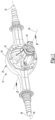
Figure 1 is a perspective view of an example of an axle assembly. -
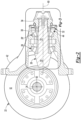
Figure 2 is a section view of the axle assembly ofFigure 1 along section line 2-2 with an axle housing of the axle assembly omitted for clarity. -
Figure 3 is a magnified view of a portion ofFigure 3 . -
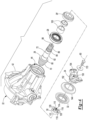
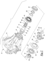
Figure 4 is an exploded view of the portion of the axle assembly shown inFigure 3 . -
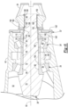
Figure 5 is a section view of a second embodiment of the axle assembly ofFigure 1 along section line 2-2 with the axle housing omitted for clarity. -
Figure 6 is a magnified view of a portion ofFigure 5 . -
Figure 7 is an exploded view of the portion of the axle assembly shown inFigure 6 . - As required, detailed embodiments of the present invention are disclosed herein; however, it is to be understood that the disclosed embodiments are merely exemplary of the invention that may be embodied in various and alternative forms. The figures are not necessarily to scale; some features may be exaggerated or minimized to show details of particular components. Therefore, specific structural and functional details disclosed herein are not to be interpreted as limiting, but merely as a representative basis for teaching one skilled in the art to variously employ the present invention.
- It will also be understood that, although the terms first, second, etc. are, in some instances, used herein to describe various elements, these elements should not be limited by these terms. These terms are only used to distinguish one element from another. For example, a first element could be termed a second element, and similarly a second element could be termed a first element without departing from the scope of the various described embodiments. The first element and the second element are both elements, but they are not the same element.
- The terminology used in the description of the various described embodiments is for the purpose of describing particular embodiments only and is not intended to be limiting. As used in the description of the various described embodiments and the appended claims, the singular forms "a", "an" and "the" are intended to include the plural forms as well, unless the context clearly indicates otherwise. It will also be understood that the term "and/or" as used herein refers to and encompasses any and all possible combinations of one or more of the associated listed items. It will be further understood that the terms "includes," "including," "comprises," and/or "comprising," when used in this specification, specify the presence of stated features, integers, steps, operations, elements, and/or components, but do not preclude the presence or addition of one or more other features, integers, steps, operations, elements, components, and/or groups thereof.
- Referring to
Figure 1 , an example of anaxle assembly 10 is shown. Theaxle assembly 10 may be provided with a motor vehicle like a truck, bus, farm equipment, mining equipment, military transport or weaponry vehicle, or cargo loading equipment for land, air, or marine vessels. The motor vehicle may include a trailer for transporting cargo in one or more embodiments. - The
axle assembly 10 is configured to provide torque to one or more traction wheel assemblies that may include a tire mounted on a wheel. The wheel may be mounted to a wheel hub that may be rotatable about a wheel axis. - One or more axle assemblies may be provided with the vehicle. In
Figure 1 , asingle axle assembly 10 is shown. As is best shown with reference toFigures 1 or2 , theaxle assembly 10 may include ahousing assembly 20, adifferential assembly 22, and at least oneaxle shaft 24. As is best shown inFigure 2 , theaxle assembly 10 includes adrive pinion 26, at least one bearingassembly 28, 28', apreload nut 30, and aseal assembly 32. Theaxle assembly 10 may also include ayoke 34. - Referring to
Figure 1 , thehousing assembly 20 receives various components of theaxle assembly 10. In addition, thehousing assembly 20 may facilitate mounting of theaxle assembly 10 to the vehicle. For instance, thehousing assembly 20 may include anaxle housing 40 and adifferential carrier 42. Optionally, one or more additional housings may be provided with thehousing assembly 20, such as an electric motor housing if an electric motor is provided with theaxle assembly 10. - The
axle housing 40 at least partially receives thedifferential assembly 22. Theaxle housing 40 may also have arm portions that receive and support theaxle shafts 24. - The
differential carrier 42 is removably mountable to theaxle housing 40. Thedifferential carrier 42 supports thedifferential assembly 22. For instance, thedifferential carrier 42 may include bearing supports upon which bearing assemblies are disposed that rotatably support thedifferential assembly 22. In at least one configuration and as is best shown inFigure 2 , thedifferential carrier 42 may also include acavity 44 through which thedrive pinion 26 may extend. - Referring to
Figure 2 , thedifferential assembly 22 is receivable inside thehousing assembly 20. Thedifferential assembly 22 may be rotatable about adifferential axis 50 and may transmit torque to theaxle shafts 24 and wheels. Thedifferential assembly 22 may be operatively connected to theaxle shafts 24 and may permit theaxle shafts 24 to rotate at different rotational speeds in a manner known by those skilled in the art. Thedifferential assembly 22 may have aring gear 52 that may have teeth the mate or mesh with the teeth of a gear of thedrive pinion 26. Accordingly, thedifferential assembly 22 may receive torque from thedrive pinion 26 via thering gear 52 and transmit torque to theaxle shafts 24. - Referring to
Figures 1 and2 , theaxle shafts 24 transmit torque between thedifferential assembly 22 and corresponding wheel hubs and wheels. Twoaxle shafts 24 may be provided such that eachaxle shaft 24 extends through a different arm portion of theaxle housing 40. Theaxle shafts 24 or a portion thereof may extend along and may be rotatable about an axis, such as thedifferential axis 50 or an axis that differs from thedifferential axis 50. Eachaxle shaft 24 may have a first end and a second end. The first end may be operatively connected to thedifferential assembly 22. The second end may be disposed opposite the first end and may be operatively connected to a wheel, such as via a wheel hub. Optionally, gear reduction may be provided between anaxle shaft 24 and a wheel. - Referring to
Figures 2-4 , thedrive pinion 26 is configured to transmit torque between a power source or torque source and thedifferential assembly 22 via thering gear 52. The power source may be of any suitable type. For instance, the power source may be an electrical power source or a non-electrical power source. An example of an electrical power source is an electrical machine like an electric motor. An example of a non-electrical power source is an internal combustion engine. In the configuration shown inFigure 1 , the power source is configured to be located remotely from theaxle assembly 10 and may be operatively connected to theaxle assembly 10 via a linkage like a shaft; however, it is contemplated that the power source, whether electrical or non-electrical, may be provided with theaxle assembly 10. - Referring to
Figures 3 and4 , thedrive pinion 26 is rotatable about anaxis 60. Theaxis 60 may be disposed substantially perpendicular to thedifferential axis 50. Thedrive pinion 26 may also extend along or around theaxis 60. In at least one configuration, thedrive pinion 26 includes agear 70 and ashaft 72. - The
gear 70 may be disposed at or near an end of theshaft 72. Thegear 70 may have a plurality of teeth that may mate with corresponding teeth on thering gear 52. The teeth of thering gear 52 and thegear 70 are simplified or not shown in the figures, but it is to be understood that the teeth of thegear 70 may have any suitable configuration that is compatible with the teeth of thering gear 52, including but not limited to spiral teeth, hypoid teeth, etc., as is known by those skilled in the art. Thegear 70 may be integrally formed with theshaft 72 or may be provided as a separate component that may be fixedly disposed on theshaft 72. - The
shaft 72 may extend from thegear 70. For instance, theshaft 72 may extend from thegear 70 in a direction that extends away from thedifferential assembly 22. In at least one configuration such as is best shown with reference toFigure 4 , theshaft 72 may include at least one outer surface, such as a firstouter surface 80 and/or a secondouter surface 82, a threadedportion 84, and aspline 86. Theshaft 72 may also include afastener hole 88. - Referring to
Figures 3 and4 , the firstouter surface 80 may extend from thegear 70 and may be an outside circumference of a portion of theshaft 72. As such, the firstouter surface 80 may face away from theaxis 60. One ormore bearing assemblies 28 that may be disposed in thecavity 44 of thedifferential carrier 42 may be disposed on the firstouter surface 80 and may rotatably support thedrive pinion 26. The bearingassemblies 28 may have any suitable configuration. For instance, a bearingassembly 28 may be configured as a roller bearing assembly that may encircle theshaft 72 and that may include a plurality of rollingelements 90 that may be disposed between aninner race 92 and anouter race 94. Theinner race 92 may extend around and may be disposed on the firstouter surface 80. Theouter race 94 may extend around the rollingelements 90 and may be disposed on or contact a supporting component, such as thedifferential carrier 42. - In the configuration shown, two bearing assemblies are provided and may be referred to as a
first bearing assembly 28 and a second bearing assembly 28' for clarity. The second bearing assembly 28' and its components are designated with the same reference numbers as thefirst bearing assembly 28 but include a prime symbol after the number. Thus, the second bearing assembly 28' includes rolling elements 90', an inner race 92', and anouter race 94' that are analogous to the corresponding components of thefirst bearing assembly 28. - The second
outer surface 82, if provided, may be axially positioned or positioned along theaxis 60 between the firstouter surface 80 and the threadedportion 84. The secondouter surface 82 may be an outside circumference of a portion of theshaft 72. As such, the secondouter surface 82 may face away from theaxis 60. The secondouter surface 82 may have a smaller diameter than the firstouter surface 80. One ormore spacers 100 may be disposed on the secondouter surface 82. Thespacers 100 may be configured as rings that may encircle theshaft 72 and may be axially positioned between theinner races 92, 92' of thebearing assemblies 28, 28' to inhibit axial movement of theinner races 92, 92' toward each other. Thespacers 100 may also transmit preload force between the bearingassemblies 28, 28'. The second bearing assembly 28' may also be disposed on the secondouter surface 82. - It is contemplated that the second
outer surface 82 may be omitted. For instance, the axial length of the firstouter surface 80 may be increased and the second bearing assembly 28', thespacers 100, or both may be disposed on the firstouter surface 80. It is also contemplated that additional outer surfaces may be provided. For instance, the second bearing assembly 28' may be disposed on a third outer surface that may extend between the secondouter surface 82 and the threadedportion 84. - The threaded
portion 84 facilitates installation of thepreload nut 30. The threadedportion 84 may be axially positioned or positioned along theaxis 60 between an outer surface and thespline 86. For instance, the threadedportion 84 may be axially positioned between the secondouter surface 82 and thespline 86. The threadedportion 84 may include a thread that may spiral around theaxis 60 and mate or mesh with a corresponding thread on thepreload nut 30. In at least one configuration, the threadedportion 84 may have an outside diameter that may be smaller than the diameter of the firstouter surface 80, the secondouter surface 82, or combinations thereof. - The
spline 86, if provided, may be disposed between the threadedportion 84 and a distal end of theshaft 72. Thespline 86 may include a plurality of teeth. In at least one configuration, the teeth of thespline 86 may be disposed substantially parallel to theaxis 60 and may mate with a corresponding spline of another component, such as theyoke 34, that may operatively connect thedrive pinion 26 to the power source. Thespline 86 may have an outside diameter that may be less than the diameter of the outside diameter of the threadedportion 84. It is also contemplated that thespline 86 may be omitted. - The
fastener hole 88 may extend from a distal end of theshaft 72 toward thegear 70. Thefastener hole 88 may be disposed along theaxis 60. Thefastener hole 88 may be a threaded hole and may be configured to receive afastener 170, such as a bolt. - The
preload nut 30 is mountable to thedrive pinion 26 and engageable with a bearing assembly. In addition, thepreload nut 30 is configured to exert a preload force on the one ormore bearing assemblies 28, 28' that rotatably support thedrive pinion 26 on thedifferential carrier 42. Thepreload nut 30 may include afirst end 110, asecond end 112, ahole 114, and athread 116. In the configuration shown inFigures 2-4 , thepreload nut 30 includes an externalcircumferential surface 118 and one ormore apertures 120. - The
first end 110, which may also be referred to as a first end surface, may face away from thegear 70 and away from the first andsecond bearing assemblies 28, 28' when thepreload nut 30 is installed on thedrive pinion 26. For instance, thefirst end 110 may face toward and may engage or contact theyoke 34. - The
second end 112, which may also be referred to as a second end surface, may be disposed opposite thefirst end 110. Thesecond end 112 may face toward thegear 70 and the first andsecond bearing assemblies 28, 28' when thepreload nut 30 is installed on thedrive pinion 26. For instance, thesecond end 112 may face toward and may engage or contact the inner race 92' of the second bearing assembly 28'. - The
hole 114 may be a through hole that may extend from thefirst end 110 to thesecond end 112. Theshaft 72 of thedrive pinion 26 may be received in and may extend through thehole 114. - The
thread 116 is disposed in thehole 114. Thethread 116 may mate with the threadedportion 84 of thedrive pinion 26 to help secure thepreload nut 30 to thedrive pinion 26. In at least one configuration, thethread 116 may generally extend from thefirst end 110 toward or to thesecond end 112. - The external
circumferential surface 118 encircles and faces away from theaxis 60. The externalcircumferential surface 118 may extend between thefirst end 110 and thesecond end 112. In the configuration shown, the externalcircumferential surface 118 extends from thefirst end 110 to thesecond end 112. The external circumferential surface may be a smooth surface that may be radially disposed with respect to theaxis 60. - One or
more apertures 120 may be provided in thepreload nut 30. Theapertures 120 may receive a tool that may rotate thepreload nut 30 to tighten or loosen thepreload nut 30 to provide a desired bearing preload force. Theapertures 120 may be blind holes or through holes. In the configuration shown, theapertures 120 are configured as blind holes and extend from thefirst end 110 toward thesecond end 112. - The
seal assembly 32 is configured to seal an opening of thedifferential carrier 42 and provide a seal between thedifferential carrier 42 and thedrive pinion 26 or between thedifferential carrier 42 and one or more components that are disposed on thedrive pinion 26. - In the configuration shown in
Figures 2-4 , theseal assembly 32 encircles thepreload nut 30 and extends fromdifferential carrier 42 to thepreload nut 30. For instance, theseal assembly 32 may engage or contact the externalcircumferential surface 118 of thepreload nut 30. Theseal assembly 32 may also encircle and extend to theyoke 34. In at least one configuration and as is best shown inFigure 3 , theseal assembly 32 may include aninner member 140 and anouter member 142. Adeflector 144 may also be provided. - The
inner member 140 may extend from thedifferential carrier 42 to thepreload nut 30. For instance, theinner member 140 may extend from an internal surface of thedifferential carrier 42 that faces toward theaxis 60 and/or from an end surface of thedifferential carrier 42 that defines or encircles an opening of thecavity 44 to the externalcircumferential surface 118 of thepreload nut 30. Theinner member 140 may be fixedly disposed on thedifferential carrier 42. Thedrive pinion 26,preload nut 30, andyoke 34 may be rotatable together about theaxis 60 with respect to theinner member 140. - The
outer member 142 may extend from theyoke 34 toward thedifferential carrier 42. For instance, theouter member 142 may extend from a first yokeouter surface 158 of theyoke 34 toward thedifferential carrier 42 such that at least a portion of theouter member 142 is encircled by thedifferential carrier 42 and theinner member 140. Theouter member 142 may be rotatable about theaxis 60 with theyoke 34 and may be rotatable about theaxis 60 with respect to theinner member 140. Theouter member 142 may be axially positioned further outboard or further away from thepreload nut 30 than theinner member 140. - The
deflector 144, if provided, helps cover or conceal theseal assembly 32 and the opening of thedifferential carrier 42 in which theseal assembly 32 is received. As such, thedeflector 144 may help block or prevent some contaminants from reaching theseal assembly 32. Thedeflector 144 may be fixedly disposed on theyoke 34 and may extend away from theaxis 60 and around the end surface of thedifferential carrier 42. Thedeflector 144 may be spaced apart from thedifferential carrier 42 so that thedeflector 144 may rotate about theaxis 60 with thedrive pinion 26 and theyoke 34 and with respect to thedifferential carrier 42. Thedeflector 144 may encircle a portion of thedifferential carrier 42, theinner member 140, theouter member 142, or combinations thereof. - Referring to
Figures 3 and4 , theyoke 34 is configured to facilitate coupling of thedrive pinion 26 to the power source or to another axle assembly. For instance, theyoke 34 may be coupled to another component, such as a universal joint, which in turn may be coupled to a torque transmitting component like a drive shaft or a prop shaft. Theyoke 34 may be stationarily mounted to thedrive pinion 26. In at least one configuration, theyoke 34 includes a firstyoke end surface 150, a secondyoke end surface 152, ayoke hole 154, ayoke spline 156, a first yokeouter surface 158, a second yokeouter surface 160, or combinations thereof. - Referring primarily to
Figure 3 , the firstyoke end surface 150 may face away from thegear 70 and thepreload nut 30 when theyoke 34 is installed on thedrive pinion 26. Afastener 170, such as a bolt or bolt and washer, may be provided to inhibit axial movement of theyoke 34 or movement along theaxis 60 with respect to theshaft 72 of thedrive pinion 26. For instance, thefastener 170 may be threaded into thefastener hole 88 in theshaft 72 may engage the firstyoke end surface 150. - The second
yoke end surface 152 may be disposed opposite the firstyoke end surface 150. The secondyoke end surface 152 may face toward thegear 70. The secondyoke end surface 152 may engage or contact thefirst end 110 of thepreload nut 30 when theyoke 34 is installed on thedrive pinion 26. - Referring to
Figure 4 , theyoke hole 154 may be a through hole that may extend from the firstyoke end surface 150 to the secondyoke end surface 152. Theshaft 72 of thedrive pinion 26 may be received in theyoke hole 154. For instance, thespline 86 of theshaft 72 may be received in theyoke hole 154. As such, theyoke 34 may encircle theshaft 72. - Referring primarily to
Figure 3 , theyoke spline 156 may be disposed in theyoke hole 154. Theyoke spline 156 may include a plurality of teeth that extend toward theaxis 60. Theyoke spline 156 may mate or mesh with thespline 86 of thedrive pinion 26 to inhibit rotation of theyoke 34 about theaxis 60 with respect to thedrive pinion 26. - The first yoke
outer surface 158 faces away from theaxis 60. The first yokeouter surface 158 may extend from the secondyoke end surface 152. The first yokeouter surface 158 may be disposed closer to theaxis 60 than the externalcircumferential surface 118 of thepreload nut 30 is disposed to theaxis 60. Theseal assembly 32 may engage the first yokeouter surface 158. - The second yoke
outer surface 160 also faces away from theaxis 60. The second yokeouter surface 160 may be disposed further from theaxis 60 than the first yokeouter surface 158 is disposed from theaxis 60. Thedeflector 144 may engage the second yokeouter surface 160. - In the configuration shown in
Figures 2-4 , theyoke 34 may inhibit rotation of thepreload nut 30. For instance, thepreload nut 30 may extend axially from theinner race 92 of the bearing assembly 28' to theyoke 34. Theyoke 34 may abut thepreload nut 30 and thereby prevent rotation of thepreload nut 30 about theaxis 60 when theyoke 34 is secured to theshaft 72. - Referring to
Figures 5-7 , another configuration is shown. This configuration is similar to that shown inFigures 2-4 but includes modifications to the drive pinion, preload nut, and seal assembly. In this configuration, the seal assembly 32' encircles theshaft 72 of the drive pinion 26', extends from theshaft 72 to thedifferential carrier 42, and is spaced apart from the preload nut 30'. - Referring primarily to
Figure 6 , the drive pinion 26' extends along or around theaxis 60 and includes agear 70 as previously described and ashaft 72. Theshaft 72 includes at least one outer surface, such as a firstouter surface 80 and/or a secondouter surface 82, a threadedportion 84, and aspline 86 like that previously described. Theshaft 72 may omit thefastener hole 88 and include a journal surface 88'. - The journal surface 88' faces away from the
axis 60 and may be an outside circumferential surface of theshaft 72. The journal surface 88' may be axially positioned or positioned along theaxis 60 or axially positioned between the threadedportion 84 and thespline 86. The journal surface 88' may be an outside circumference of a portion of theshaft 72. As such, the journal surface 88' may face away from theaxis 60. The journal surface 88' may be positioned closer to theaxis 60 than the threadedportion 84 is positioned to theaxis 60. The journal surface 88' may be positioned further from theaxis 60 than thespline 86 is positioned from theaxis 60. For instance, the journal surface 88' may have a smaller diameter than the threadedportion 84 and a larger diameter than thespline 86. The seal assembly 32' may be disposed on and may engage or contact the journal surface 88'. - The preload nut 30' is configured to thread onto the threaded
portion 84 of theshaft 72 and exert a preload force on one or more bearing assemblies as previously discussed. The preload nut 30' includes afirst end 110, asecond end 112, ahole 114, and athread 116 but omits the external circumferential surface and apertures associated with the configuration inFigures 2-4 . In this configuration, the preload nut 30' may include adeformable ring 180 and atool engagement portion 182. - Referring to
Figures 6 and7 , thedeformable ring 180 may extend from thefirst end 110 toward thesecond end 112. For instance, thedeformable ring 180 may extend from thefirst end 110 to thethread 116. Thedeformable ring 180 may extend continuously around theaxis 60; however, it is contemplated that thedeformable ring 180 may be discontinuous. Thedeformable ring 180 may be deformable to engage theshaft 72 to inhibit rotation of the preload nut 30' about theaxis 60 with respect to the drive pinion 26'. For instance, thedeformable ring 180 may be deformed or staked against the drive pinion 26', such as into a recess or indentation in theshaft 72 of the drive pinion 26' to inhibit rotation of the preload nut 30'. Thedeformable ring 180 may unthreaded. - The
tool engagement portion 182 may be axially positioned between thedeformable ring 180 and thesecond end 112. In at least one configuration, thetool engagement portion 182 may include a plurality of intersecting flat surfaces that may be grasped by a tool, such as a wrench or socket, to facilitate tightening and loosening of the preload nut 30'. - The seal assembly 32' is axially positioned or positioned along the
axis 60 between the preload nut 30' and theyoke 34. The seal assembly 32' is configured to engage the journal surface 88' of theshaft 72. The seal assembly 32' may include aninner member 140' and an outer member 142'. - The
inner member 140' may extend from thedifferential carrier 42 to the drive pinion 26'. For instance, theinner member 140' may extend from an internal surface and/or an end surface of thedifferential carrier 42 that defines the opening of thedifferential carrier 42 to the journal surface 88' of the drive pinion 26'. Theinner member 140' may be spaced apart from the preload nut 30' and theyoke 34. Theinner member 140' may be fixedly disposed on thedifferential carrier 42. The drive pinion 26' andyoke 34 may be rotatable together about theaxis 60 with respect to theinner member 140'. - The outer member 142' may extend from the
yoke 34 toward thedifferential carrier 42. For instance, the outer member 142' may extend from a first yokeouter surface 158 of theyoke 34 toward thedifferential carrier 42 such that the outer member 142' encircles thedifferential carrier 42 and theinner member 140'. As such, the outer member 142' may be rotatable about theaxis 60 with theyoke 34 and may be rotatable about theaxis 60 with respect to theinner member 140'. A portion of theinner member 140' may engage or extend to the outer member 142' to facilitate sealing between theinner member 140' in the outer member 142'. - The configuration shown in
Figures 5-7 may include one or more retaining features, such as afirst retaining feature 190 and asecond retaining feature 192. - Referring to
Figure 6 , thefirst retaining feature 190 may be a separate component from theshaft 72. Thefirst retaining feature 190 may be installable onto theshaft 72 and removable from theshaft 72. Thefirst retaining feature 190 may engage theyoke 34 to inhibit movement of theyoke 34 away from the preload nut 30', or to the right from the perspective shown inFigure 6 . For instance, thefirst retaining feature 190 may engage or contact the firstyoke end surface 150. Thefirst retaining feature 190 may be received in afirst groove 194 of theshaft 72. Thefirst retaining feature 190 may have any suitable configuration. For instance, thefirst retaining feature 190 may be configured as a clip, snap ring, or the like. - The
second retaining feature 192 may be a separate component from theshaft 72. Thesecond retaining feature 192 may be installable onto theshaft 72 and removable from theshaft 72. Thesecond retaining feature 192 may engage theyoke 34 to inhibit movement of theyoke 34 toward from the preload nut 30', or to the left from the perspective shown inFigure 6 . For instance, thesecond retaining feature 192 may engage or contact the firstyoke end surface 150, an at end of theyoke spline 156, or combinations thereof. Thesecond retaining feature 192 may be received in asecond groove 196 of theshaft 72. In at least one configuration, thesecond retaining feature 192 may be received in theyoke hole 154 and theyoke 34 may encircle thesecond retaining feature 192. Thesecond retaining feature 192 may have any suitable configuration. For instance, thesecond retaining feature 192 may be configured as a clip, snap ring, or the like. - In the configurations shown in
Figures 2-4 and5-7 , thepreload nut 30, 30' may be tightened to exert a desired axial preload force against one ormore bearing assemblies 28, 28', which may inhibit or prevent spinning of theinner race 92, 92' with respect to thedrive pinion 26, 26' and/or spinning of theouter race differential carrier 42 and remove excess play, which may result in reduced bearing life. Theseal assembly 32, 32' andyoke 34 may be installed after the preload force is set. - An axle assembly as described above may allow a bearing preload to be set independently from the yoke. More specifically, the bearing preload may be set using a preload nut that may be tightened to exert a desired axial preload force against one or more bearing assemblies prior to installation of the yoke. The yoke in turn may either not engage the preload nut or may engage the preload nut in a manner that prevents loosening of the preload nut. This may allow the preload force to be set independent of installation or removal of the yoke, independent of installing or tightening of a fastener that may secure the yoke to the drive pinion, and avoid contact between the yoke and a bearing assembly. As such, the bearing preload force may be set more accurately and installation and removal of the yoke may have no impact or a negligible impact on the established bearing preload force. The present invention may also allow a seal assembly to provide sealing between the differential carrier and a component other than the yoke, such as the preload nut or the shaft of the drive pinion, which may permit installation and removal of the yoke without affecting sealing integrity. The present invention may also allow the seal assembly to be installed after the bearing preload is set. As such, installation and removal of the seal assembly may have no impact or a negligible impact on an established bearing preload force.
- While exemplary embodiments are described above, it is not intended that these embodiments describe all possible forms of the invention. Rather, the words used in the specification are words of description rather than limitation, and it is understood that various changes may be made without departing from the spirit and scope of the invention. Additionally, the features of various implementing embodiments may be combined to form further embodiments of the invention.
Claims (15)
- An axle assembly comprising:a differential carrier;a drive pinion that is rotatable about an axis, the drive pinion including:a gear; anda shaft that extends from the gear, the shaft having a threaded portion;a bearing assembly that encircles the shaft and that rotatably supports the drive pinion on the differential carrier;a preload nut that has a thread that mates with the threaded portion and that engages the bearing assembly and exerts a preload force on the bearing assembly; anda seal assembly that encircles the preload nut and extends from the preload nut to the differential carrier.
- The axle assembly of claim 1 wherein the preload nut has an external circumferential surface that encircles and faces away from the axis and wherein the seal assembly engages the external circumferential surface, preferably the seal assembly has an inner member that extends from the differential carrier to the external circumferential surface and an outer member that extends from the first outer yoke surface toward the differential carrier and that is encircled by the differential carrier and the inner member.
- The axle assembly of any preceding claim wherein the shaft includes an outer surface and a spline, and the threaded portion is axially positioned between the outer surface and the spline.
- The axle assembly of any preceding claim further comprising a yoke that encircles and is mounted to the shaft.
- The axle assembly of claim 4 wherein the yoke inhibits rotation of the preload nut, and/or wherein the preload nut extends axially from an inner race of the bearing assembly to the yoke, and/or the seal assembly encircles and engages the preload nut and the yoke.
- The axle assembly of claim 4 or claim 5 wherein the preload nut has an end surface that engages the yoke and a plurality of blind holes that extend from the end surface toward the bearing assembly.
- The axle assembly of claim 4 or claim 5 or claim 6 further comprising a deflector that extends from the yoke and that encircles a portion of the differential carrier, preferably the yoke has a yoke end surface that engages the preload nut, a first outer yoke surface that faces away from the axis and extends from the yoke end surface, and a second yoke outer surface that faces away from the axis and is disposed further from the axis than the first outer yoke surface is disposed from the axis, and/or the seal assembly engages the first outer yoke surface and the deflector engages the second yoke outer surface.
- The axle assembly of claim 2 or any of claims 3 to 6 when dependent on claim 2 wherein the yoke has a yoke end surface that engages the preload nut, a first outer yoke surface that faces away from the axis and extends from the yoke end surface, and a second yoke outer surface that faces away from the axis and is disposed further from the axis than the first outer yoke surface is disposed from the axis, wherein the first outer yoke surface is disposed closer to the axis than the external circumferential surface is disposed to the axis and/or the first outer yoke surface is disposed closer to the axis than the second yoke outer surface is disposed to the axis.
- An axle assembly comprising:a differential carrier;a drive pinion that is rotatable about an axis, the drive pinion including:a gear; anda shaft that extends from the gear, the shaft having a threaded portion; anda bearing assembly that encircles the shaft and that rotatably supports the drive pinion on the differential carrier;a preload nut that has a thread that mates with the threaded portion and that engages the bearing assembly and exerts a preload force on the bearing assembly; anda seal assembly that encircles the shaft and extends from the shaft to the differential carrier.
- The axle assembly of claim 9 wherein the seal assembly is spaced apart from the preload nut.
- The axle assembly of claim 9 or claim 10 further comprising a yoke that encircles and is mounted to the shaft, wherein the seal assembly is axially positioned between the preload nut and the yoke.
- The axle assembly of claim 11 wherein the shaft has a spline that engages the yoke and a journal surface that faces away from the axis and is axially positioned between the threaded portion and the spline, wherein the seal assembly engages the journal surface.
- The axle assembly of claim 12 wherein the journal surface is positioned closer to the axis than the threaded portion is positioned to the axis and is positioned further from the axis than the spline is positioned from the axis.
- The axle assembly of claim 12 or claim 13 wherein the seal assembly has an inner member that extends from the differential carrier to the journal surface and is spaced apart from the preload nut and the yoke, and/or an outer member that extends from the yoke, engages the inner member, and encircles the differential carrier and the inner member.
- The axle assembly of claim any one of claims 11-14 further comprising first and second retaining features that are separate from the shaft and are mounted to the shaft, wherein the first retaining feature engages the yoke to inhibit movement of yoke away from the preload nut and the second retaining feature engages the yoke to inhibit movement of the yoke toward the preload nut, preferably the first and second retaining features are received in first and second grooves in the shaft, respectively, and/or the yoke encircles the second retaining feature.
Applications Claiming Priority (1)
| Application Number | Priority Date | Filing Date | Title |
|---|---|---|---|
| US18/159,450 US20240246410A1 (en) | 2023-01-25 | 2023-01-25 | Axle assembly having a drive pinion and a preload nut |
Publications (1)
| Publication Number | Publication Date |
|---|---|
| EP4407212A1 true EP4407212A1 (en) | 2024-07-31 |
Family
ID=89715680
Family Applications (1)
| Application Number | Title | Priority Date | Filing Date |
|---|---|---|---|
| EP24153777.8A Pending EP4407212A1 (en) | 2023-01-25 | 2024-01-24 | Axle assembly having a drive pinion and a preload nut |
Country Status (3)
| Country | Link |
|---|---|
| US (1) | US20240246410A1 (en) |
| EP (1) | EP4407212A1 (en) |
| CN (1) | CN118386733A (en) |
Citations (7)
| Publication number | Priority date | Publication date | Assignee | Title |
|---|---|---|---|---|
| US20030130047A1 (en) * | 2002-01-08 | 2003-07-10 | Brissette Ronald N. | Quick connect/disconnect driveline assembly |
| US20100247016A1 (en) * | 2009-03-24 | 2010-09-30 | Rivett Eric Alan | Multi-piece spacer for setting bearing preload |
| US20100267455A1 (en) * | 2007-11-30 | 2010-10-21 | Brian Michael Valovick | Constant Velocity Joint Attachment Method |
| US20140105680A1 (en) * | 2012-10-15 | 2014-04-17 | Dana Automotive Systems Group, Llc | Drive pinion fastening assembly |
| US10316950B2 (en) | 2017-03-10 | 2019-06-11 | Arvinmeritor Technology, Llc | Axle assembly having a drive pinion and a bearing preload element |
| US20200232548A1 (en) * | 2019-01-22 | 2020-07-23 | Ford Global Technologies, Llc | Drive unit pinion and method of installation |
| WO2021011953A1 (en) * | 2019-07-12 | 2021-01-21 | Linamar Corporation | Differential with a plastic deflector having a stainless steel running surface |
-
2023
- 2023-01-25 US US18/159,450 patent/US20240246410A1/en active Pending
-
2024
- 2024-01-24 CN CN202410103341.5A patent/CN118386733A/en active Pending
- 2024-01-24 EP EP24153777.8A patent/EP4407212A1/en active Pending
Patent Citations (7)
| Publication number | Priority date | Publication date | Assignee | Title |
|---|---|---|---|---|
| US20030130047A1 (en) * | 2002-01-08 | 2003-07-10 | Brissette Ronald N. | Quick connect/disconnect driveline assembly |
| US20100267455A1 (en) * | 2007-11-30 | 2010-10-21 | Brian Michael Valovick | Constant Velocity Joint Attachment Method |
| US20100247016A1 (en) * | 2009-03-24 | 2010-09-30 | Rivett Eric Alan | Multi-piece spacer for setting bearing preload |
| US20140105680A1 (en) * | 2012-10-15 | 2014-04-17 | Dana Automotive Systems Group, Llc | Drive pinion fastening assembly |
| US10316950B2 (en) | 2017-03-10 | 2019-06-11 | Arvinmeritor Technology, Llc | Axle assembly having a drive pinion and a bearing preload element |
| US20200232548A1 (en) * | 2019-01-22 | 2020-07-23 | Ford Global Technologies, Llc | Drive unit pinion and method of installation |
| WO2021011953A1 (en) * | 2019-07-12 | 2021-01-21 | Linamar Corporation | Differential with a plastic deflector having a stainless steel running surface |
Also Published As
| Publication number | Publication date |
|---|---|
| CN118386733A (en) | 2024-07-26 |
| US20240246410A1 (en) | 2024-07-25 |
Similar Documents
| Publication | Publication Date | Title |
|---|---|---|
| US10208846B2 (en) | Axle assembly having a drive pinion support bearing and a method of assembly | |
| US8047724B2 (en) | Bearing device for wheel | |
| EP3275714B1 (en) | Axle assembly having a wheel mount disposed on a planet carrier | |
| US6884196B1 (en) | Inter-axle differential with improved differential gear mounting arrangement | |
| EP3275695B1 (en) | Axle assembly having an axle shaft subassembly | |
| EP3351817B1 (en) | Slip yoke assembly | |
| KR20190130311A (en) | Hub built-in type constant velocity joint apparatus | |
| EP4027038A1 (en) | Axle assembly having a drive pinion and a preload nut and a method of assembly | |
| US7699405B2 (en) | Vehicle wheel end assemblies and methods of assembly thereof | |
| EP3398834B1 (en) | Wheel end assembly having a deflector | |
| EP4407212A1 (en) | Axle assembly having a drive pinion and a preload nut | |
| JP5250942B2 (en) | Rolling bearing device for wheels | |
| EP4091834A2 (en) | Axle assembly having a brake drum | |
| EP4112353A1 (en) | Axle assembly having an interaxle differential unit | |
| EP4098457A1 (en) | Axle assembly having a brake drum and method of assembly | |
| US12104685B2 (en) | Axle assembly and a unitary yoke-shaft | |
| US20240068514A1 (en) | Axle assembly and a unitary yoke-shaft | |
| US11994198B1 (en) | Axle assembly having a preload mechanism | |
| US10941846B2 (en) | Differential assembly having an overhanging ring gear | |
| US11602989B2 (en) | Axle assembly having an interaxle differential unit | |
| US11698123B1 (en) | Axle assembly having an interaxle differential unit | |
| US20240025206A1 (en) | Axle assembly having a wheel end assembly and a gear reduction unit | |
| EP4299354A1 (en) | Wheel end assembly | |
| KR102488467B1 (en) | Planet gear assembly for drive axle | |
| JPH05196100A (en) | Clamp for bearing cap of differential gear and car axle assembly |
Legal Events
| Date | Code | Title | Description |
|---|---|---|---|
| PUAI | Public reference made under article 153(3) epc to a published international application that has entered the european phase |
Free format text: ORIGINAL CODE: 0009012 |
|
| STAA | Information on the status of an ep patent application or granted ep patent |
Free format text: STATUS: THE APPLICATION HAS BEEN PUBLISHED |
|
| AK | Designated contracting states |
Kind code of ref document: A1 Designated state(s): AL AT BE BG CH CY CZ DE DK EE ES FI FR GB GR HR HU IE IS IT LI LT LU LV MC ME MK MT NL NO PL PT RO RS SE SI SK SM TR |