EP4027033B1 - Rad und bremsanordnung mit mechanischem anschlag - Google Patents
Rad und bremsanordnung mit mechanischem anschlag Download PDFInfo
- Publication number
- EP4027033B1 EP4027033B1 EP21218085.5A EP21218085A EP4027033B1 EP 4027033 B1 EP4027033 B1 EP 4027033B1 EP 21218085 A EP21218085 A EP 21218085A EP 4027033 B1 EP4027033 B1 EP 4027033B1
- Authority
- EP
- European Patent Office
- Prior art keywords
- wheel
- mechanical stop
- actuator
- disc stack
- disc
- Prior art date
- Legal status (The legal status is an assumption and is not a legal conclusion. Google has not performed a legal analysis and makes no representation as to the accuracy of the status listed.)
- Active
Links
Images


Classifications
-
- B—PERFORMING OPERATIONS; TRANSPORTING
- B64—AIRCRAFT; AVIATION; COSMONAUTICS
- B64C—AEROPLANES; HELICOPTERS
- B64C25/00—Alighting gear
- B64C25/32—Alighting gear characterised by elements which contact the ground or similar surface
- B64C25/42—Arrangement or adaptation of brakes
-
- F—MECHANICAL ENGINEERING; LIGHTING; HEATING; WEAPONS; BLASTING
- F16—ENGINEERING ELEMENTS AND UNITS; GENERAL MEASURES FOR PRODUCING AND MAINTAINING EFFECTIVE FUNCTIONING OF MACHINES OR INSTALLATIONS; THERMAL INSULATION IN GENERAL
- F16D—COUPLINGS FOR TRANSMITTING ROTATION; CLUTCHES; BRAKES
- F16D55/00—Brakes with substantially-radial braking surfaces pressed together in axial direction, e.g. disc brakes
- F16D55/24—Brakes with substantially-radial braking surfaces pressed together in axial direction, e.g. disc brakes with a plurality of axially-movable discs, lamellae, or pads, pressed from one side towards an axially-located member
- F16D55/26—Brakes with substantially-radial braking surfaces pressed together in axial direction, e.g. disc brakes with a plurality of axially-movable discs, lamellae, or pads, pressed from one side towards an axially-located member without self-tightening action
- F16D55/36—Brakes with a plurality of rotating discs all lying side by side
-
- B—PERFORMING OPERATIONS; TRANSPORTING
- B60—VEHICLES IN GENERAL
- B60B—VEHICLE WHEELS; CASTORS; AXLES FOR WHEELS OR CASTORS; INCREASING WHEEL ADHESION
- B60B27/00—Hubs
- B60B27/0047—Hubs characterised by functional integration of other elements
- B60B27/0052—Hubs characterised by functional integration of other elements the element being a brake disc
-
- F—MECHANICAL ENGINEERING; LIGHTING; HEATING; WEAPONS; BLASTING
- F16—ENGINEERING ELEMENTS AND UNITS; GENERAL MEASURES FOR PRODUCING AND MAINTAINING EFFECTIVE FUNCTIONING OF MACHINES OR INSTALLATIONS; THERMAL INSULATION IN GENERAL
- F16D—COUPLINGS FOR TRANSMITTING ROTATION; CLUTCHES; BRAKES
- F16D55/00—Brakes with substantially-radial braking surfaces pressed together in axial direction, e.g. disc brakes
- F16D55/24—Brakes with substantially-radial braking surfaces pressed together in axial direction, e.g. disc brakes with a plurality of axially-movable discs, lamellae, or pads, pressed from one side towards an axially-located member
- F16D55/26—Brakes with substantially-radial braking surfaces pressed together in axial direction, e.g. disc brakes with a plurality of axially-movable discs, lamellae, or pads, pressed from one side towards an axially-located member without self-tightening action
- F16D55/36—Brakes with a plurality of rotating discs all lying side by side
- F16D55/40—Brakes with a plurality of rotating discs all lying side by side actuated by a fluid-pressure device arranged in or one the brake
-
- F—MECHANICAL ENGINEERING; LIGHTING; HEATING; WEAPONS; BLASTING
- F16—ENGINEERING ELEMENTS AND UNITS; GENERAL MEASURES FOR PRODUCING AND MAINTAINING EFFECTIVE FUNCTIONING OF MACHINES OR INSTALLATIONS; THERMAL INSULATION IN GENERAL
- F16D—COUPLINGS FOR TRANSMITTING ROTATION; CLUTCHES; BRAKES
- F16D65/00—Parts or details
- F16D65/005—Components of axially engaging brakes not otherwise provided for
-
- F—MECHANICAL ENGINEERING; LIGHTING; HEATING; WEAPONS; BLASTING
- F16—ENGINEERING ELEMENTS AND UNITS; GENERAL MEASURES FOR PRODUCING AND MAINTAINING EFFECTIVE FUNCTIONING OF MACHINES OR INSTALLATIONS; THERMAL INSULATION IN GENERAL
- F16D—COUPLINGS FOR TRANSMITTING ROTATION; CLUTCHES; BRAKES
- F16D65/00—Parts or details
- F16D65/14—Actuating mechanisms for brakes; Means for initiating operation at a predetermined position
- F16D65/16—Actuating mechanisms for brakes; Means for initiating operation at a predetermined position arranged in or on the brake
- F16D65/18—Actuating mechanisms for brakes; Means for initiating operation at a predetermined position arranged in or on the brake adapted for drawing members together, e.g. for disc brakes
- F16D65/186—Actuating mechanisms for brakes; Means for initiating operation at a predetermined position arranged in or on the brake adapted for drawing members together, e.g. for disc brakes with full-face force-applying member, e.g. annular
-
- B—PERFORMING OPERATIONS; TRANSPORTING
- B64—AIRCRAFT; AVIATION; COSMONAUTICS
- B64C—AEROPLANES; HELICOPTERS
- B64C25/00—Alighting gear
- B64C25/32—Alighting gear characterised by elements which contact the ground or similar surface
- B64C25/42—Arrangement or adaptation of brakes
- B64C25/44—Actuating mechanisms
-
- F—MECHANICAL ENGINEERING; LIGHTING; HEATING; WEAPONS; BLASTING
- F16—ENGINEERING ELEMENTS AND UNITS; GENERAL MEASURES FOR PRODUCING AND MAINTAINING EFFECTIVE FUNCTIONING OF MACHINES OR INSTALLATIONS; THERMAL INSULATION IN GENERAL
- F16D—COUPLINGS FOR TRANSMITTING ROTATION; CLUTCHES; BRAKES
- F16D2121/00—Type of actuator operation force
- F16D2121/02—Fluid pressure
- F16D2121/04—Fluid pressure acting on a piston-type actuator, e.g. for liquid pressure
-
- F—MECHANICAL ENGINEERING; LIGHTING; HEATING; WEAPONS; BLASTING
- F16—ENGINEERING ELEMENTS AND UNITS; GENERAL MEASURES FOR PRODUCING AND MAINTAINING EFFECTIVE FUNCTIONING OF MACHINES OR INSTALLATIONS; THERMAL INSULATION IN GENERAL
- F16D—COUPLINGS FOR TRANSMITTING ROTATION; CLUTCHES; BRAKES
- F16D2127/00—Auxiliary mechanisms
Definitions
- the present disclosure relates to brake systems of a vehicle.
- Vehicles such as aircrafts, may use a wheel brake system that includes a multi-disc brake system.
- the multi-disc brake system may include a disc stack comprising plurality of rotor discs engaged with a wheel and a plurality of stator discs interleaved with the rotor discs.
- the rotor discs and wheel are configured to rotate around an axle, while the stator discs remain stationary.
- the brake system may displace pistons against a pressure plate to compress the rotating rotor discs engaged with the wheel against the stationary stator discs, therefore producing torque that decelerates the rotational motion of the wheel.
- the rotor discs may be engaged with the wheel via rotor drive keys positioned on an interior surface of the wheel.
- stator discs may be engaged with a stationary torque tube surrounding the axle via splines positioned on the torque tube.
- the brake system may be configured to compress the rotor discs and the stator discs between the piston and a backing plate supported by the torque tube.
- US 6 702 068 B1 discloses an aircraft wheel and brake assembly having a wheel member journaled for rotation on a fixed member, which fixed member supports a torque tube member.
- a plurality of primary friction disks are carried by splines on the wheel member while a plurality of secondary friction disks are carried by splines on the torque tube member with such secondary disks interleaved with the primary friction disks for axial movement towards one end of the torque tube.
- An actuator such as a plurality of pistons, is mounted on the fixed member to urge all the friction disks into frictional engagement with each other and against a stationary disk on the one end of the torque tube.
- a rigid disk is positioned between the actuator and the pluralities of friction disks, and acts as a pressure plate.
- EP 3 453 614 A1 discloses an aircraft wheel braking arrangement comprising a landing gear structure, a torque tube extending in an outboard direction from the landing gear structure, and an actuator housing disposed outboard from the torque tube.
- An actuator piston may extend in an inboard direction from the actuator housing for applying a force to a brake stack surrounding the torque tube.
- the present invention describes wheel assemblies configured to help limit a maximum displacement achievable between a piston housing and a brake disc stack when a brake system is utilized to reduce and/or substantially prevent a rotation of a wheel.
- the brake system is configured to compress a brake disc stack to reduce and/or limit rotational motion of the wheel about the wheel axis.
- an actuator may be configured to compress the disc stack against a portion of a torque tube engaged with the disc stack.
- the compression force of the actuator may cause a linear deformation of the torque tube.
- the linear deformation may require additional piston travel to assure the compression force on the disc stack is maintained during certain operating conditions, such as a Rejected Take-Off (RTO) stop.
- RTO Rejected Take-Off
- the assembly disclosed here uses a mechanical stop configured to unload some portion of the compression force from the torque tube when the torque tube linearly deforms.
- the mechanical stop is configured to limit the maximum distance between the actuator housing and the disc stack at end of life, even during compression of the brake disc stack.
- the assemblies disclosed herein are configured to help limit the displacement between the actuator housing and the brake disc stack when the actuator exerts the compression force.
- the assembly is configured to help limit the displacement when the compression force causes an excessive linear deformation of the torque tube.
- the assembly described herein may be configured to reduce and/or minimize additional piston travel that may be required to assure the compression force on the disc stack is maintained during certain operating conditions, such as a Rejected Take-Off (RTO) stop.
- RTO Rejected Take-Off
- the assembly may be configured to limit the maximum distance between the piston housing and the disc stack at end of life, even during compression of the brake disc stack.
- rotor drive keys 24 may be configured to receive a torque from a braking system (not shown) configured to reduce and/or cease a rotation of wheel 10.
- Rotor drive keys 24 may be integrally formed with interior surface 16, or may be separate from and mechanically affixed to interior surface 16.
- rotor discs 43, 44, 45 and/or stator discs 47, 48 can each be substantially annular discs surrounding axial assembly 28.
- Stator discs 47, 48 are coupled to torque tube 31 via spline 49 and remain rotationally stationary with torque tube 31 (and axial assembly 28) as wheel 10 rotates.
- Rotor discs 43, 44, 45 are rotationally coupled to rotor drive key 25 and interior surface 16 and rotate substantially synchronously with wheel 10 around axis A.
- actuator 39 is configured to compress disc stack 42 against a backing plate 50.
- Backing plate 50 may be supported by torque tube 31.
- backing plate 50 may be configured to be substantially stationary with respect to torque tube 31.
- Wheel 10 may rotate around backing plate 50 when wheel 10 rotates around torque tube 31.
- Brake system 40 may be configured such that the compression force exerted on disc stack 42 by actuator 39 causes disc stack 42 to translate toward backing plate 50.
- the compression force may cause rotor discs 43, 44, 45 to translate over rotor drive key 25 toward backing plate 50 and cause stator discs 47, 48 to translate over spline 49 toward backing plate 50.
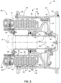
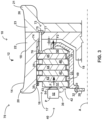
- FIG. 3 illustrates an example assembly 70 including an example portion of wheel 10 and an example portion of brake system 40 within wheel well 17 defined by wheel 10.
- FIG. 3 depicts a cross-section of wheel 10 and selected portions of brake system 40, with the cross-section taken parallel to axial direction A in FIG. 1 .
- rotor drive key 25 is supported by wheel 10 via one or more fasteners 35 (e.g., bolts) attaching rotor drive key 25 to wheel 10, and a torque tube 31 is engaged with a portion of an axial assembly 28 by, e.g., bolt 32.
- fasteners 35 e.g., bolts
- FIG. 3 illustrates actuator 39 with piston 54 in a first position and in a second position relative to actuator body 52.
- FIG. 3 illustrates the first position of piston 54 in dashed line, and the second position of piston 54 in solid line.
- Actuator 39 may be configured to translate piston 54 from the first position to the second position to cause piston face 53 to exert the compression force on disc stack 42.
- the first position and the second position may be displaced from each other by an amount of piston travel T. That is, actuator 39 may be configured to define a first displacement between piston face 53 and a point P on actuator body 39 in the first position, and define a second displacement between piston face 53 and the point P in the second position, wherein the first displacement and the second displacement define the piston travel T.
- Actuator 39 may be configured to cause piston 54 to translate over the piston travel T to exert the compression force on disc stack 42.
- Disc stack 42 is configured to cause a reduction in the rotational speed of wheel 10 and/or substantially prevent rotational movement of wheel 10 (e.g., in a parked condition) when actuator 39 compresses disc stack 42.
- a compression force exerted by actuator 39 causes friction surfaces on the rotating rotor discs 43, 44, 45 to engage friction surfaces on the relatively stationary stator discs 47, 48.
- Engagement with stator discs 47, 48 and/or friction surfaces of pressure plate 51 and/or backing plate 50 causes rotor discs 43, 44, 45 to exert a torque on wheel 10 (e.g., via rotor drive key 25), reducing the speed of wheel 10.
- rotor discs 43, 44, 45 may resist rotational motion of wheel 10.
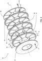
- FIG. 4 illustrates a perspective view of an example disc stack 42 illustrating stator discs 47, 48 interleaved with rotor discs 43, 44, 45.
- Disc stack 42 may be positioned between pressure plate 51 and backing plate 50.
- Axis A is included for reference to FIGS. 1-3 .
- Disc stack 42 is illustrated in an uncompressed condition with opposing friction surfaces of adjacent stator and rotor discs disengaged.
- an air gap G exists between rotor disc 43 and adjacent stator disc 47 such that friction surface 56 of rotor disc 43 and friction surface 58 of stator disc 47 are substantially disengaged (e.g., not in contact with each other).
- the air gap G may have any suitable value (e.g., may be larger or smaller than illustrated, relative to disc stack 42).
- Each of stator discs 47, 48 and rotor discs 43, 44, 45 may have a first friction surface (e.g., friction surface 56 of rotor disc 43) and a second friction surface (e.g., friction surface 60 of rotor disc 43) on an opposite side of the respective disc from the first friction surface.
- each of stator discs 47, 48 and rotor discs 43, 44, 45 may be substantially annular shaped discs, but may have other shapes in other examples.
- pressure plate 51 and/or backing plate 50 may include a plurality of spline slots (e.g., spline slot 71 on inner perimeter 72 of pressure plate 51) configured to cause pressure plate 51 and/or backing plate 50 to substantially remain rotationally stationary with respect to torque tube 31.
- actuator 39 FIG. 2 and 3
- disc stack 42 is compressed between pressure plate 51 and backing plate 50, eliminating the gap G and causing the friction surfaces (e.g., friction surface 56 and friction surface 58) to engage.
- Backing plate 50 is configured to exert a reaction force F1 on disc stack 42 in response to the compression force F against backing plate 50.
- backing plate 50 is configured to engage a portion of torque tube 31, such that torque tube 31 substantially limits movement of backing plate 50 in a direction away from pressure plate 51 in a direction parallel to axis A.
- backing plate 50 is configured to exert a force F2 ( FIG. 3 and 4 ) on torque tube 31 in response to the compression force F.
- torque tube 31 FIGS 2 and 3
- torque tube 31 may be configured such that when actuator 39 exerts the compression force F on disc stack 42, torque tube 31 experiences a force F2 based on the compression force F.
- the compression force F and the force F2 are substantially parallel to axis A.
- disc stack 42 may include one or more rotor discs such as rotor disc 43, 44, 45, one or more stator discs such as stator disc 47, 48, and other components configured to rotate and/or translate as a substantially rigid body with at least one of the rotor discs (e.g., rotor discs 43, 44, 45) and/or the stator discs (e.g., stator discs 47, 48).
- rotor discs such as rotor disc 43, 44, 45
- stator discs such as stator disc 47, 48
- torque tube 31 may comprise a material having a ductility that results in a linear deformation of torque tube 31 under some conditions (e.g., under a high heat load following an emergency stop of a vehicle using brake system 40).
- actuator 39 exerts the compression force F causing the force F2 on torque tube 31
- the ductility of the material may result in the force F2 causing the linear deformation.
- the linear deformation of torque tube 31 may be substantially parallel to axis A.
- the linear deformation may cause torque tube 31 to extend towards wheel 10, reducing the displacement D ( FIG. 3 ) between torque tube 31 and wheel 10.
- the linear deformation of torque tube 31 may increase a displacement between actuator body 39 (e.g., point P) and disc stack 42, increasing the piston travel T required by actuator 39 in order to assure that the compression force F is maintained.
- Assembly 70 is configured to limit the piston travel T which may be required by actuator 39 by limiting a maximum distance between actuator housing 52 (e.g., point P) and disc stack 42 under certain operating conditions, such as a Rejected Take-Off (RTO) stop.
- RTO Rejected Take-Off
- the reduction in the displacement D between torque tube 31 and wheel 10 may be more pronounced toward the end of the operating life for a given disc stack 42.
- the linear deformation of torque tube 31 may cause a greater reduction of the displacement D.
- the greater reduction in the displacement D may occur as a result of higher temperatures caused by a reduction in heat sink material as disc stack 42 and/or other components of brake assembly 40 wear over life.
- Ensuring that at least some portion of the displacement D remains between torque tube 31 and wheel 10 may limit the dependence of the displacement D on the thickness of disc stack 42, allowing for less frequent replacement of disc stack 42.
- the available travel of piston 54 may become a factor as the individual disc thicknesses are reduced.
- assembly 70 includes a mechanical stop 74 configured to limit a translation of disc stack 42 when actuator 39 exerts the compression force F on disc stack 42 under certain operation conditions.
- mechanical stop 74 is configured to limit a translation of disc stack 42 in a direction substantially parallel to axis A.
- mechanical stop 74 may be configured to limit the translation of disc stack 42 when torque tube 31 linearly deforms in a manner that leads to a reduction in the displacement D (e.g., when actuator 39 causes the linear deformation of torque tube 31).
- Mechanical stop 74 may be configured to limit the translation of disc stack 42 when torque tube 31 linearly deforms over a displacement less than the displacement D.
- mechanical stop 74 is configured to exert a reaction force on disc stack 42 when mechanical stop 74 encounters disc stack 42.
- mechanical stop 74 may be configured such that, when torque tube 31 linearly deforms under the influence of force F2, mechanical stop 74 encounters and exerts a reaction force on disc stack 42 to reduce the force F2 experienced by torque tube 31.
- the reduction of the force F2 on torque tube 31 may substantially cease the linear deformation and resulting extension of torque tube 31 toward wheel 10, preserving at least some portion of the displacement D between torque tube 31 and wheel 10, and limiting the linear translation of disc stack 42 when actuator 39 exerts the compression force F.
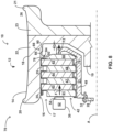
- FIG. 5 illustrates assembly 70 with mechanical stop 74 encountering disc stack 42.
- Actuator 39 has translated piston 54 from a first position (indicated in dashed line) to a second position (indicated in solid line) to cause piston face 53 to encounter disc stack 42 (e.g., pressure plate 51) to exert the compression force F on disc stack 42.
- Actuator 39 has caused piston 54 to translate over the piston travel Tm to exert the compression force F.
- the compression force F causes a linear translation of disc stack 42 toward backing plate 50.
- Mechanical stop 74 may be configured to encounter one or more rotor discs (e.g., rotor discs 43, 44, 45) and/or one or more stator discs (e.g., stator discs 47, 48) when the compression force F causes torque tube 31 to linearly deform under certain conditions.
- mechanical stop 74 encountering disc stack 42 (e.g., drive insert 76 and/or rotor disc 45)
- mechanical stop 74 exerts a reaction force F3 opposing compression force F.
- the exertion of the reaction force F3 reduces and/or substantially eliminates the necessary reaction force imparted by backing plate 50, reducing and/or substantially eliminating the force F4 on torque tube 31.
- Reducing and/or substantially eliminating the force F4 on torque tube 31 may reduce and/or substantially eliminate further linear deformation of torque tube 31.
- Reducing and/or substantially eliminating the further linear deformation of torque tube 31 limits further linear translation of disc stack 42 in a direction away from actuator body 52 (e.g., point P), limiting the amount of piston travel Tm required to maintain a sufficient compression force F.
- brake system 40 limits a maximum distance between actuator housing 52 (e.g., point P) and disc stack 42 under certain operating conditions. This may reduce the reserve capacity requirements of actuator 39 which might be otherwise required in the absence of mechanical stop 74.
- mechanical stop 74 is configured to reduce and/or substantially eliminate the force F4 on torque tube 31 (e.g., by exerting the reaction force F3) when actuator 39 causes torque tube 31 to experience a threshold linear deformation.
- Mechanical stop 74 may be configured to encounter disc stack 42 to exert the reaction force F3 when torque tube 31 experiences a linear deformation sufficient to reduce the displacement D ( FIG. 3 ) to the displacement D2 ( FIG. 5 ).
- Mechanical stop 74 may be configured to at least partially unload torque tube 31 (e.g., by exerting the reaction force F3) to substantially cease the linear deformation, in order to limit the maximum distance between actuator housing 52 (e.g., point P) and disc stack 42.
- assembly 70 is configured such that actuator 39 compresses disc stack 42 at least partially against mechanical stop 74 when mechanical stop 74 encounters disc stack 42.
- assembly 70 may be configured such that actuator 39 compresses disc stack 42 against both backing plate 50 and mechanical stop 74, such that mechanical stop 74 substantially acts to reduce the amount of compression force F transmitted to torque tube 31.
- Mechanical stop 74 may be configured to possess a greater axial stiffness than torque tube 31 in a direction substantially parallel to the direction of the compression force F.
- mechanical stop 74 may comprises a material and/or have a geometry causing the axial stiffness of mechanical stop 74 to exceed that of torque tube 31. The greater axial stiffness may act to ensure mechanical stop 74 sufficiently unloads torque tube 31 without allowing additional linear deformation of mechanical stop 74 and/or torque tube 31.
- FIG. 6 illustrates assembly 70 with disc stack 42 in an uncompressed condition (e.g., without a compression force exerted by actuator 39).
- Assembly 70 is configured such that, absent a compression force from actuator 39, assembly 70 substantially maintains a clearance (measured in a direction parallel to axis A) between disc stack 42 and mechanical stop 74.
- Assembly 70 may be configured such that, when actuator 39 compresses disc stack 42, disc stack 42 encounters backing plate 50 prior to mechanical stop 74.
- actuator 39 defines a first length L1 between actuator 39 and mechanical stop 74 and a second length L2 between actuator 39 and backing plate 50, with the first length L1 greater than the second length L2.
- the first length L1 and the second length L2 may be defined by a specific point on actuator 39, such as point P on actuator body 52.
- the first length L1 and the second length L2 may be substantially parallel.
- the first length L1 and the second length L2 may be substantially parallel to axis A.
- Mechanical stop 74 may be supported in any manner sufficient to allow mechanical 74 to encounter disc stack 42 and exert reaction force F3 on disc stack 42.
- Mechanical stop 74 may be configured such that a movement of mechanical stop 74 is substantially limited in response to the exertion of reaction force F3.
- the movement of mechanical stop 74 may be substantially limited by any portion of wheel 10, brake system 40, axial assembly 28 ( FIG. 1 ), or some other component or system sufficient to limit the movement of mechanical stop 74 when mechanical stop 74 exerts the reaction force F3.
- Mechanical stop 74 may be configured such that, when mechanical stop 74 exerts the reaction force F3 on disc stack 42, some portion of wheel 10, brake system 40, axial assembly 28 ( FIG.
- mechanical stop 74 is rotationally coupled to wheel 10, such that a rotation of wheel 10 causes a rotation of mechanical stop 74.
- mechanical stop 74 may be configured to rotate synchronously with wheel 10.
- mechanical stop 74 is rotationally coupled with wheel 10 and configured to encounter a portion of disc stack 42 (e.g., rotor disc 45 and/or drive insert 76) rotationally coupled to wheel 10, in order to substantially avoid contact between mechanical stop 74 and portions of disc stack 42 configured to be rotationally mismatched with mechanical stop 74. This may serve to minimize or even prevent contact between components configured to rotate with wheel 10 (e.g., mechanical stop 74) and components configured to remain substantially stationary relative to torque tube 31. Such contact may result in a need for unscheduled maintenance or early replacement of one or more components of wheel 10 or brake system 40.
- FIG. 7 illustrates another example mechanical stop 80, which is configured as a step or ledge engaged with wheel 10.
- Mechanical stop 80 is an example of mechanical stop 74.
- Mechanical stop 80 extends from the interior surface 16 of wheel 10 (e.g., extends radially inward from interior surface 16).
- Mechanical stop 80 may be configured to act as a substantially rigid body relative to wheel 10.
- mechanical stop 80 defines a bearing surface 82 configured to encounter disc stack 42 when torque tube 31 experiences a threshold linear deformation (e.g., a linear deformation causing the displacement D2 ( FIG. 5 )).
- Bearing surface 82 may be configured to exert the reaction force F3 ( FIG. 5 ) on disc stack 42 when bearing surface 82 encounters disc stack 42.
- bearing surface 82 is configured to substantially face some portion of disc stack 42.
- Bearing surface 82 may be configured to substantially abut some portion of disc stack 42 when mechanical stop 80 encounters disc stack 42.
- Bearing surface 82 may be a substantially planar surface in some examples and a curvilinear surface in other examples.
- bearing surface 82 defines a surface complementary to a surface of disc stack 42.
- bearing surface 82 may be configured to complement a surface of a brake disc (e.g., rotor disc 45) when bearing surface 82 encounters the surface of the brake disc.
- support bearing surface 82 comprises a first planar surface and the surface of the brake disc defines a second planar surface, where the first and second planar surfaces are substantially parallel (e.g., parallel or nearly parallel to the extent permitted by manufacturing tolerances) when disc stack 42 is positioned within wheel well 17.
- Wheel component 86 is configured to limit movement of mechanical stop 84 when mechanical stop 84 exerts a reaction force (e.g., reaction force F3 ( FIG. 5 )) on disc stack 42.
- mechanical stop 84 is configured such that, when actuator 39 compresses disc stack 42 against mechanical stop 84, mechanical stop 84 transmits a force to wheel component 86 caused by the compression force of actuator 39 acting on mechanical stop 84.
- Wheel component 86 may be configured to exert a substantially equal and opposite force on mechanical stop 84 to limit the movement of mechanical stop 84 in a direction parallel to axis A.
- Wheel 10 is configured to limit movement of wheel component 86 relative to wheel 10 when wheel component 86 exerts a force on mechanical stop 84 (e.g., when actuator 39 causes mechanical stop 84 to transmit force to wheel component 86).
- wheel 10 may be configured to limit motion of wheel component 86 in a direction substantially parallel to the direction of a compression force (e.g., compression force F ( FIGS. 3 , 5 ) exerted by actuator 39 on disc stack 42.
- Wheel 10 may be configured to exert a substantially equal and opposite force on wheel component 86 when mechanical stop 84 transmits force to wheel component 86.
- mechanical stop 84 may be configured to substantially transfer some portion of the compression force F exerted by actuator 39 from disc stack 42 to wheel 10.
- Mechanical stop 84 may be configured to reduce and/or substantially eliminate the load on torque tube 31 caused by actuator 39, such that linear deformation of torque tube 31 reduces and/or substantially ceases and a maximum distance between actuator housing 52 (e.g., point P) and disc stack 42 is limited.
- Mechanical stops 102, 104, 106 may be configured to exert the reaction substantially force around a perimeter of rotor disc 43, 44, 45 and/or stator disc 47, 48.
- Assembly 70 may include any number of mechanical stops arranged in any manner sufficient to cause one or more of the mechanical stops to encounter disc stack 42 ( FIGS. 3 , 5 , 6 ) when actuator 39 compresses disc stack 42 (e.g., when actuator 39 causes torque tube 31 to experience the threshold linear deformation).
- Each of mechanical stops 102, 104, 106 may be radially displaced from axis A.
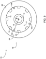
- FIG. 9 illustrates mechanical stop 102 radially displaced from axis A by the radius R.
- Each of mechanical stops 102, 104, 106 may be radially displaced from axis A by an individual radius from axis A. The individual radii may define a different displacement for each mechanical stop and/or substantially similar displacements for one or more mechanical stops.
- mechanical stops 102, 104, 106 are positioned with wheel well 17 to define a substantially circumferential pattern around axis A. Mechanical stops 102, 104, 106 may be evenly or unevenly spaced around axis A.
- Mechanical stops 102, 104, 106 may be spaced such that a spacing distance (e.g., an arc length) between adjacent mechanical stops is substantially equal around axis A.
- Mechanical stops 102, 204, 106 may be spaced such that the spacing distance (e.g., the arc length) between adjacent mechanical stops varies around axis A.
- the spacing distance and/or arc length may be defined in a place substantially perpendicular to axis A.
- each mechanical stop 102, 104, 106 is configured to reside substantially between adjacent rotor drive keys in the plurality of rotor drive keys 24.
- FIG. 9 illustrates mechanical stop 102 positioned substantially between rotor drive key 25 and the adjacent rotor drive key 15.
- Mechanical stop 102 may be configured to reside closer to rotor drive key 15 than rotor drive key 25, further away rotor drive key 15 than rotor drive key 25, or substantially equidistant from rotor drive key 25 and rotor drive key 15.
- mechanical stop 102 may extend substantially from rotor drive key 25 to rotor drive key 15, such that mechanical stop 102 is configured to exert the reaction force on disc stack 42 over a larger area (e.g., to reduce stress on disc stack 42).
- Assembly 70 may include any suitable number of mechanical stops between adjacent rotor drive keys (e.g., rotor drive key 25 and rotor drive key 15) and the mechanical stops may be arranged in any pattern relative to the adjacent rotor drive keys.
- a first mechanical stop and a second mechanical stop can be between rotor drive key 25 and rotor drive key 15, with the first mechanical stop closer to rotor drive key 25 than rotor drive key 15 and the second mechanical stop closer to rotor drive key 15 than rotor drive key 25.
- Mechanical stops described herein, including mechanical stops 74, 80, 84, 102, 104, 106, as well as wheel 10 and brake system 40, and the components thereof, may be made from any suitable material.
- the material may be any material of suitable strength for the intended use of mechanical stops 74, 80, 84, 102, 104, 106, wheel 10, brake system 40, and the components thereof.
- the material includes a metal or a metal alloy.
- the material may include a nickel alloy or steel alloy.
- the material may include stainless steel.
- Mechanical stops 74, 80, 84, 102, 104, 106, wheel 10, brake system 40, and the components thereof can be formed using any suitable technique.
- Mechanical stops 74, 80, 84, 102, 104, 106, wheel 10, brake system 40, and the components thereof may be forged, casted, made from bar stock, additive manufactured (e.g., three-dimensionally (3D) printed), extruded, drawn, or be produced using other suitable methods.
- mechanical stops 74, 80, 84, 102, 104, 106, wheel 10, brake system 40, and the components thereof may be machined to define the configurations described herein.
- Mechanical stops 74, 80, 84, 102, 104, 106, wheel 10, brake system 40, and the components thereof may be formed without having to be substantially machined.
- wheel 10 may be finish machined from a near-net-shaped aluminum forging and contain an axial assembly and/or wheel rim for assembly of brake system 40 and/or mechanical stop 74, 80, 84, 102, 104, 106 onto wheel 10.
- wheel 10 may be manufactured in a different manner.
- wheel 10 may be obtained rather than manufactured.
- Wheel 10 may be made of any suitable material.
- wheel 10 includes a metal or a metal alloy.
- wheel 10 may include aluminum, a nickel alloy, a steel alloy (e.g., stainless steel), titanium, a carbon-composite material, or magnesium.
- Brake discs described herein including rotor discs 43, 44, 45 and stator discs 47, 48, may be manufactured from any suitable material.
- the brake discs described herein may be manufactured from a metal or a metal alloy, such as a steel alloy.
- the brake discs may be manufactured using a ceramic material, such as a ceramic composite.
- the brake discs may be manufactured from a carbon-carbon composite material.
- the brake discs may be manufactured using a carbon-carbon composite material having a high thermal stability, a high wear resistance, and/or stable friction properties.
- the brake discs may include a carbon material with a plurality of carbon fibers and densifying material. The carbon fibers may be arranged in a woven or non-woven as either a single layer or multilayer structure.
- FIG. 10 is a flow diagram illustrating an example method for compressing a disc stack using an actuator. While the technique is described with reference to specific example wheel 10, brake system 40, and mechanical stops 74, 80, 84, 102, 104, 106 described herein, the technique may be used with other components in other examples.
- Mechanical stop 74, 80, 84, 102, 104, 106 may be configured to reduce the reaction force exerted by torque tube 31 on backing plate 50 when mechanical stop 74, 80, 84, 102, 104, 106 exerts the reaction force F3.
- mechanical stop 74, 80, 84, 102, 104, 106 is configured to limit the linear displacement of disc stack 42 when mechanical stop 74, 80, 84, 102, 104, 106 encounters disc stack 42.
- Mechanical stop 74, 80, 84, 102, 104, 106 may be configured to limit and/or substantially cease the linear deformation of torque tube 31 when mechanical stop 74, 80, 84, 102, 104, 106 encounters disc stack 42.
- mechanical stop 74, 80, 84, 102, 104, 106 is a step or ledge supported and/or defined by wheel 10.
- mechanical stop 74, 80, 84, 102, 104, 106 is supported by a wheel component 86 of wheel 10.
- Wheel component 86 may be a rotor drive key 25, 15 in a plurality of rotor drive keys 24 coupled to an interior surface 16 of wheel 10.
Landscapes
- Engineering & Computer Science (AREA)
- General Engineering & Computer Science (AREA)
- Mechanical Engineering (AREA)
- Aviation & Aerospace Engineering (AREA)
- Braking Arrangements (AREA)
Claims (14)
- Anordnung (70), umfassend:ein Rad (10), das dazu konfiguriert ist, sich um eine Radachse (A) zu drehen;ein Bremsensystem (40), umfassend:einen Scheibenstapel (42), umfassend eine Rotorscheibe (43, 44, 45, 46) und eine Statorscheibe (47, 48), wobei die Rotorscheibe (43, 44, 45, 46) drehbar mit dem Rad (10) gekoppelt ist, und wobei das Rad (10) dazu konfiguriert ist, sich relativ zu der Statorscheibe (47, 48) zu drehen; undeinen Aktuator (39), der ein Aktuatorgehäuse definiert und dazu konfiguriert ist, den Scheibenstapel (42) zu komprimieren,wobei das Bremsensystem (40) dazu konfiguriert ist, den Scheibenstapel (42) durch Begrenzen der linearen Bewegung des Scheibenstapels (42) zu komprimieren, indem eine Reaktionskraft auf den Scheibenstapel (42) ausgeübt wird, wenn der Aktuator (39) den Scheibenstapel (42) komprimiert, undwobei ein Teil des Bremsensystems (40) dazu konfiguriert ist, sich linear zu verformen, wenn das Bremsensystem (40) die Reaktionskraft ausübt; undeinen mechanischen Anschlag (74, 80, 84, 102, 104, 106, 204), der dazu konfiguriert ist, die durch das Bremsensystem (40) ausgeübte Reaktionskraft zu reduzieren, wenn die lineare Verformung des Teils des Bremsensystems (40) veranlasst, dass der mechanische Anschlag (74, 80, 84, 102, 104, 106, 204) in Berührung mit dem Bremsensystem (40) kommt, sodass der mechanische Anschlag (74, 80, 84, 102, 104, 106, 204) eine lineare Verschiebung des Scheibenstapels (42) relativ zu dem Aktuatorgehäuse begrenzt,gekennzeichnet dadurch, dassder mechanische Anschlag (74, 80, 84, 102, 104, 106, 204) drehbar mit dem Rad (10) gekoppelt ist.
- Anordnung (70) nach Anspruch 1, wobei der mechanische Anschlag (74, 80, 84, 102, 104, 106, 204) dazu konfiguriert ist, in Berührung mit dem Scheibenstapel (42) zu kommen, wenn der mechanische Anschlag (74, 80, 84, 102, 104, 106, 204) in Berührung mit dem Bremsensystem (40) kommt.
- Anordnung (70) nach Anspruch 1 oder Anspruch 2, wobei der mechanische Anschlag (74, 80, 84, 102, 104, 106, 204) dazu konfiguriert ist, mindestens einen Teil der Reaktionskraft auf das Rad (10) zu übertragen.
- Anordnung (70) nach einem der Ansprüche 1 bis 3, wobei der mechanische Anschlag (74, 80, 84, 102, 104, 106, 204) dazu konfiguriert ist, eine Verschiebung zwischen dem Bremsensystem (40) und dem Rad (10) aufrechtzuerhalten.
- Anordnung (70) nach Anspruch 4, wobei das Bremsensystem (40) ein Torsionsrohr (31) beinhaltet, wobei das Rad (10) dazu konfiguriert ist, sich relativ zu dem Torsionsrohr (31) zu drehen, und wobei der mechanische Anschlag (74, 80, 84, 102, 104, 106, 204) dazu konfiguriert ist, die Verschiebung zwischen dem Torsionsrohr (31) und dem Rad (10) aufrechtzuerhalten.
- Anordnung (70) nach einem der Ansprüche 1 bis 5, ferner umfassend eine Radkomponente (86), die an dem Rad (10) befestigt ist, wobei die Radkomponente (86) den mechanischen Anschlag (74, 80, 84, 102, 104, 106, 204) beinhaltet.
- Anordnung (70) nach einem der Ansprüche 1 bis 6, wobei der mechanische Anschlag (74, 80, 84, 102, 104, 106, 204) eine Lagerfläche (82, 92), die durch eine Innenfläche (16) des Rades (10) definiert ist, beinhaltet, wobei die Lagerfläche (82, 92) dazu konfiguriert ist, in Berührung mit dem Bremsscheibenstapel (42) zu kommen.
- Anordnung (70) nach einem der Ansprüche 1 bis 7, ferner umfassend eine Trägerplatte (50), die dazu konfiguriert ist, in Berührung mit dem Scheibenstapel (42) zu kommen, wenn der Aktuator (39) den Scheibenstapel (42) komprimiert, wobei das Rad (10) dazu konfiguriert ist, sich relativ zu der Trägerplatte (50) zu drehen, und wobei die Trägerplatte (50) dazu konfiguriert ist, sich in eine axiale Richtung des Rades (10) zu bewegen, wenn sich der Teil des Bremsensystems (40) linear verformt.
- Anordnung (70) nach einem der Ansprüche 1 bis 8, wobei das Bremsensystem (40) ein Torsionsrohr (31) beinhaltet, das dazu konfiguriert ist, einen Teil der Reaktionskraft auszuüben, und wobei der mechanische Anschlag (74, 80, 84, 102, 104, 106, 204) dazu konfiguriert ist, den durch das Torsionsrohr (31) ausgeübten Teil der Reaktionskraft zu reduzieren, wenn der mechanische Anschlag (74, 80, 84, 102, 104, 106, 204) in Berührung mit dem Bremsensystem (40) kommt und der Aktuator (39) den Scheibenstapel (42) komprimiert, sodass der mechanische Anschlag (74, 80, 84, 102, 104, 106, 204) die durch das Bremsensystem (40) ausgeübte Reaktionskraft reduziert und die lineare Verschiebung des Scheibenstapels (42) relativ zu dem Aktuatorgehäuse begrenzt.
- Anordnung (70) nach einem der Ansprüche 1 bis 9, wobei die Anordnung ferner eine Trägerplatte (50) umfasst, die dazu konfiguriert ist, in Berührung mit dem Scheibenstapel (42) zu kommen, wenn der Aktuator (39) den Scheibenstapel (42) komprimiert, wobei:der Aktuator (39) dazu konfiguriert ist, den Scheibenstapel (42) unter Verwendung einer Kompressionskraft zu komprimieren,der Aktuator (39) eine erste Länge (L1) zwischen dem Aktuator (39) und dem mechanischen Anschlag (74, 80, 84, 102, 104, 106, 204) in Abwesenheit der Kompressionskraft definiert,der Aktuator (39) eine zweite Länge (L2) zwischen dem Aktuator (39) und der Trägerplatte (50) in Abwesenheit der Kompressionskraft definiert, wobei die erste und die zweite Länge in paralleler Richtung gemessen werden, unddie erste Länge größer ist als die zweite Länge.
- Anordnung (70) nach einem der Ansprüche 1 bis 10, wobei der mechanische Anschlag (74, 80, 84, 102, 104, 106, 204) dazu konfiguriert ist, in Berührung mit einem Teil des Scheibenstapels (42) zu kommen, der drehbar mit dem Rad (10) gekoppelt ist.
- Verfahren, umfassend:Komprimieren eines Scheibenstapels (42) eines Bremsensystems (40) unter Verwendung eines Aktuators (39) des Bremsensystems (40), wobei der Scheibenstapel (42) eine Rotorscheibe (43, 44, 45, 46), die drehbar mit einem Rad (10) gekoppelt ist, und eine Statorscheibe (47, 48) beinhaltet, wobei das Rad (10) dazu konfiguriert ist, sich um eine Radachse (A) zu drehen, wobei das Bremsensystem (40) eine Reaktionskraft auf den Scheibenstapel (42) ausübt, wenn der Aktuator (39) den Scheibenstapel (42) komprimiert, und wobei ein mechanischer Anschlag (74, 80, 84, 102, 104, 106, 204) drehbar mit dem Rad gekoppelt ist; undBegrenzen der Bewegung des Scheibenstapels (42) durch Reduzieren der von dem Bremsensystem (40) ausgeübten Reaktionskraft durch Veranlassen, dass das Bremsensystem (40) in Berührung mit dem mechanischen Anschlag (74, 80, 84, 102, 104, 106, 204) kommt unter Verwendung der Kompression des Scheibenstapels (42) durch den Aktuator (39).
- Verfahren nach Anspruch 12, wobei das Verfahren ferner Folgendes umfasst:
Veranlassen, dass der mechanische Anschlag (74, 80, 84, 102, 104, 106, 204) mit dem Bremsensystem (40) in Berührung kommt, indem er die Rotorscheibe (43, 44, 45, 46) kontaktiert. - Verfahren nach einem der Ansprüche 12 oder 13, wobei eine Trägerplatte (50) in Berührung mit dem Scheibenstapel (42) kommt, wenn der Aktuator (39) den Scheibenstapel (42) komprimiert, wobei:der Aktuator (39) dazu konfiguriert ist, den Scheibenstapel (42) unter Verwendung einer Kompressionskraft zu komprimieren,der Aktuator (39) eine erste Länge (L1) zwischen dem Aktuator (39) und dem mechanischen Anschlag (74, 80, 84, 102, 104, 106, 204) in Abwesenheit der Kompressionskraft definiert,der Aktuator (39) eine zweite Länge (L2) zwischen dem Aktuator (39) und der Trägerplatte (50) in Abwesenheit der Kompressionskraft definiert, wobei die erste und die zweite Länge in paralleler Richtung gemessen werden, unddie erste Länge größer ist als die zweite Länge.
Applications Claiming Priority (1)
| Application Number | Priority Date | Filing Date | Title |
|---|---|---|---|
| US17/248,135 US12054005B2 (en) | 2021-01-11 | 2021-01-11 | Wheel and brake assembly with mechanical stop |
Publications (2)
| Publication Number | Publication Date |
|---|---|
| EP4027033A1 EP4027033A1 (de) | 2022-07-13 |
| EP4027033B1 true EP4027033B1 (de) | 2025-07-09 |
Family
ID=79185878
Family Applications (1)
| Application Number | Title | Priority Date | Filing Date |
|---|---|---|---|
| EP21218085.5A Active EP4027033B1 (de) | 2021-01-11 | 2021-12-29 | Rad und bremsanordnung mit mechanischem anschlag |
Country Status (3)
| Country | Link |
|---|---|
| US (1) | US12054005B2 (de) |
| EP (1) | EP4027033B1 (de) |
| CN (1) | CN114750934A (de) |
Families Citing this family (1)
| Publication number | Priority date | Publication date | Assignee | Title |
|---|---|---|---|---|
| IL277061A (en) * | 2020-08-31 | 2022-03-01 | Ree Automotive Ltd | Wheel drive assembly |
Family Cites Families (20)
| Publication number | Priority date | Publication date | Assignee | Title |
|---|---|---|---|---|
| US4878563A (en) | 1984-07-13 | 1989-11-07 | The B.F. Goodrich Company | Brake apparatus |
| US5205382A (en) | 1990-10-09 | 1993-04-27 | The B. F. Goodrich Company | Aircraft brake |
| JP3599123B2 (ja) * | 1994-06-22 | 2004-12-08 | 本田技研工業株式会社 | トランスミッション用油圧ブレーキ |
| US5542517A (en) * | 1994-12-05 | 1996-08-06 | Ford Motor Company | Balance dam return spring for friction element of an automatic transmission |
| US6702068B1 (en) | 1994-12-08 | 2004-03-09 | Goodrich Corporation | Aircraft brake |
| JP3429399B2 (ja) * | 1995-08-30 | 2003-07-22 | ジヤトコ株式会社 | 締結装置 |
| US5937985A (en) * | 1997-08-04 | 1999-08-17 | Ford Motor Company | Retaining ring in a hydraulically actuated friction element assembly for an automatic transmission |
| GB2352784A (en) | 1999-08-04 | 2001-02-07 | Moog Inc | Energy-absorbing brake |
| US6543596B2 (en) * | 2000-04-24 | 2003-04-08 | Borgwarner, Inc. | Multi-disk friction device having low-drag characteristics |
| DE10331370A1 (de) * | 2003-07-11 | 2005-03-03 | Zf Friedrichshafen Ag | Automatgetriebe mit einem hydraulisch betätigbaren Schaltglied |
| US7129658B2 (en) | 2003-10-15 | 2006-10-31 | Honeywell International Inc. | Electro-mechanical actuator braking apparatus and method using motor commutation sensor output to derive piston displacement |
| US7523816B2 (en) | 2006-03-06 | 2009-04-28 | Honeywell International Inc. | Method and brake assembly retention device with automatic operation |
| DE102013005732A1 (de) | 2013-04-05 | 2014-10-09 | Festo Ag & Co. Kg | Linearsteller |
| FR3016011B1 (fr) * | 2013-12-30 | 2017-06-09 | Chassis Brakes Int Bv | Actionneur entraine par pignon a glissiere axiale, et frein a tambour et dispositif de freinage ainsi equipes |
| FR3016010B1 (fr) * | 2013-12-30 | 2016-02-12 | Chassis Brakes Int Bv | Dispositif de frein a tambour incluant un frein de stationnement fonctionnant en mode duo servo, vehicule et procedes d'assemblage associes |
| GB2524762B (en) * | 2014-04-01 | 2020-06-17 | Airbus Operations Ltd | Drive system for aircraft landing gear |
| US20160159213A1 (en) * | 2014-12-05 | 2016-06-09 | GM Global Technology Operations LLC | Hybrid electric ground mobility system |
| FR3030001B1 (fr) * | 2014-12-12 | 2018-04-20 | Safran Landing Systems | Actionneur de freinage pour frein hydraulique de roue d`aeronef. |
| US9909632B2 (en) | 2015-12-28 | 2018-03-06 | Goodrich Corporation | Plate assemblies including floating wear linings for multi-disk brake systems and methods for reducing vibration in a multi-disk brake system |
| US10145429B1 (en) * | 2017-09-08 | 2018-12-04 | Goodrich Corporation | Aircraft brake torque and clamp force reaction through landing gear structure |
-
2021
- 2021-01-11 US US17/248,135 patent/US12054005B2/en active Active
- 2021-12-29 EP EP21218085.5A patent/EP4027033B1/de active Active
- 2021-12-31 CN CN202111682680.6A patent/CN114750934A/zh active Pending
Also Published As
| Publication number | Publication date |
|---|---|
| US12054005B2 (en) | 2024-08-06 |
| CN114750934A (zh) | 2022-07-15 |
| EP4027033A1 (de) | 2022-07-13 |
| US20220219489A1 (en) | 2022-07-14 |
Similar Documents
| Publication | Publication Date | Title |
|---|---|---|
| EP3869060B1 (de) | Rotorantriebsschlüsselanordnung | |
| EP0941419B1 (de) | Mehrscheiben-bremsbetätigungsvorrichtung zur schwingungsdämpfung | |
| EP3889040B1 (de) | Bremssystem | |
| EP4027033B1 (de) | Rad und bremsanordnung mit mechanischem anschlag | |
| EP4006375B1 (de) | Kolbenkappe | |
| US20220003287A1 (en) | Brake disc assembly | |
| EP4386229B1 (de) | Bremsanordnung mit mehreren steifigkeiten | |
| EP4435285A1 (de) | Drehmomentpadbefestigungsanordnung | |
| EP4464911A1 (de) | Drehmomentkissen | |
| US20250122915A1 (en) | Spline assembly | |
| US20250243915A1 (en) | Braking system attachment assembly | |
| US12590615B2 (en) | Brake disc system | |
| US12577993B2 (en) | Reduced profile piston adjuster | |
| US12449009B2 (en) | Brake disc insert assembly | |
| EP4378766B1 (de) | Bremsanordnung |
Legal Events
| Date | Code | Title | Description |
|---|---|---|---|
| PUAI | Public reference made under article 153(3) epc to a published international application that has entered the european phase |
Free format text: ORIGINAL CODE: 0009012 |
|
| STAA | Information on the status of an ep patent application or granted ep patent |
Free format text: STATUS: REQUEST FOR EXAMINATION WAS MADE |
|
| 17P | Request for examination filed |
Effective date: 20211229 |
|
| AK | Designated contracting states |
Kind code of ref document: A1 Designated state(s): AL AT BE BG CH CY CZ DE DK EE ES FI FR GB GR HR HU IE IS IT LI LT LU LV MC MK MT NL NO PL PT RO RS SE SI SK SM TR |
|
| P01 | Opt-out of the competence of the unified patent court (upc) registered |
Effective date: 20230421 |
|
| STAA | Information on the status of an ep patent application or granted ep patent |
Free format text: STATUS: EXAMINATION IS IN PROGRESS |
|
| 17Q | First examination report despatched |
Effective date: 20240129 |
|
| GRAP | Despatch of communication of intention to grant a patent |
Free format text: ORIGINAL CODE: EPIDOSNIGR1 |
|
| STAA | Information on the status of an ep patent application or granted ep patent |
Free format text: STATUS: GRANT OF PATENT IS INTENDED |
|
| INTG | Intention to grant announced |
Effective date: 20250225 |
|
| GRAS | Grant fee paid |
Free format text: ORIGINAL CODE: EPIDOSNIGR3 |
|
| GRAA | (expected) grant |
Free format text: ORIGINAL CODE: 0009210 |
|
| STAA | Information on the status of an ep patent application or granted ep patent |
Free format text: STATUS: THE PATENT HAS BEEN GRANTED |
|
| AK | Designated contracting states |
Kind code of ref document: B1 Designated state(s): AL AT BE BG CH CY CZ DE DK EE ES FI FR GB GR HR HU IE IS IT LI LT LU LV MC MK MT NL NO PL PT RO RS SE SI SK SM TR |
|
| REG | Reference to a national code |
Ref country code: GB Ref legal event code: FG4D |
|
| REG | Reference to a national code |
Ref country code: CH Ref legal event code: EP |
|
| REG | Reference to a national code |
Ref country code: IE Ref legal event code: FG4D |
|
| REG | Reference to a national code |
Ref country code: DE Ref legal event code: R096 Ref document number: 602021033724 Country of ref document: DE |
|
| REG | Reference to a national code |
Ref country code: NL Ref legal event code: MP Effective date: 20250709 |
|
| PG25 | Lapsed in a contracting state [announced via postgrant information from national office to epo] |
Ref country code: PT Free format text: LAPSE BECAUSE OF FAILURE TO SUBMIT A TRANSLATION OF THE DESCRIPTION OR TO PAY THE FEE WITHIN THE PRESCRIBED TIME-LIMIT Effective date: 20251110 |
|
| PG25 | Lapsed in a contracting state [announced via postgrant information from national office to epo] |
Ref country code: NL Free format text: LAPSE BECAUSE OF FAILURE TO SUBMIT A TRANSLATION OF THE DESCRIPTION OR TO PAY THE FEE WITHIN THE PRESCRIBED TIME-LIMIT Effective date: 20250709 |
|
| REG | Reference to a national code |
Ref country code: AT Ref legal event code: MK05 Ref document number: 1812056 Country of ref document: AT Kind code of ref document: T Effective date: 20250709 |
|
| PG25 | Lapsed in a contracting state [announced via postgrant information from national office to epo] |
Ref country code: IS Free format text: LAPSE BECAUSE OF FAILURE TO SUBMIT A TRANSLATION OF THE DESCRIPTION OR TO PAY THE FEE WITHIN THE PRESCRIBED TIME-LIMIT Effective date: 20251109 |
|
| PG25 | Lapsed in a contracting state [announced via postgrant information from national office to epo] |
Ref country code: NO Free format text: LAPSE BECAUSE OF FAILURE TO SUBMIT A TRANSLATION OF THE DESCRIPTION OR TO PAY THE FEE WITHIN THE PRESCRIBED TIME-LIMIT Effective date: 20251009 |
|
| REG | Reference to a national code |
Ref country code: LT Ref legal event code: MG9D |
|
| PG25 | Lapsed in a contracting state [announced via postgrant information from national office to epo] |
Ref country code: AT Free format text: LAPSE BECAUSE OF FAILURE TO SUBMIT A TRANSLATION OF THE DESCRIPTION OR TO PAY THE FEE WITHIN THE PRESCRIBED TIME-LIMIT Effective date: 20250709 |
|
| PG25 | Lapsed in a contracting state [announced via postgrant information from national office to epo] |
Ref country code: FI Free format text: LAPSE BECAUSE OF FAILURE TO SUBMIT A TRANSLATION OF THE DESCRIPTION OR TO PAY THE FEE WITHIN THE PRESCRIBED TIME-LIMIT Effective date: 20250709 |
|
| PG25 | Lapsed in a contracting state [announced via postgrant information from national office to epo] |
Ref country code: HR Free format text: LAPSE BECAUSE OF FAILURE TO SUBMIT A TRANSLATION OF THE DESCRIPTION OR TO PAY THE FEE WITHIN THE PRESCRIBED TIME-LIMIT Effective date: 20250709 |
|
| PGFP | Annual fee paid to national office [announced via postgrant information from national office to epo] |
Ref country code: FR Payment date: 20251223 Year of fee payment: 5 |
|
| PG25 | Lapsed in a contracting state [announced via postgrant information from national office to epo] |
Ref country code: GR Free format text: LAPSE BECAUSE OF FAILURE TO SUBMIT A TRANSLATION OF THE DESCRIPTION OR TO PAY THE FEE WITHIN THE PRESCRIBED TIME-LIMIT Effective date: 20251010 |
|
| PG25 | Lapsed in a contracting state [announced via postgrant information from national office to epo] |
Ref country code: SE Free format text: LAPSE BECAUSE OF FAILURE TO SUBMIT A TRANSLATION OF THE DESCRIPTION OR TO PAY THE FEE WITHIN THE PRESCRIBED TIME-LIMIT Effective date: 20250709 |
|
| PG25 | Lapsed in a contracting state [announced via postgrant information from national office to epo] |
Ref country code: LV Free format text: LAPSE BECAUSE OF FAILURE TO SUBMIT A TRANSLATION OF THE DESCRIPTION OR TO PAY THE FEE WITHIN THE PRESCRIBED TIME-LIMIT Effective date: 20250709 |
|
| PG25 | Lapsed in a contracting state [announced via postgrant information from national office to epo] |
Ref country code: BG Free format text: LAPSE BECAUSE OF FAILURE TO SUBMIT A TRANSLATION OF THE DESCRIPTION OR TO PAY THE FEE WITHIN THE PRESCRIBED TIME-LIMIT Effective date: 20250709 Ref country code: PL Free format text: LAPSE BECAUSE OF FAILURE TO SUBMIT A TRANSLATION OF THE DESCRIPTION OR TO PAY THE FEE WITHIN THE PRESCRIBED TIME-LIMIT Effective date: 20250709 |
|
| PG25 | Lapsed in a contracting state [announced via postgrant information from national office to epo] |
Ref country code: RS Free format text: LAPSE BECAUSE OF FAILURE TO SUBMIT A TRANSLATION OF THE DESCRIPTION OR TO PAY THE FEE WITHIN THE PRESCRIBED TIME-LIMIT Effective date: 20251009 |
|
| PG25 | Lapsed in a contracting state [announced via postgrant information from national office to epo] |
Ref country code: ES Free format text: LAPSE BECAUSE OF FAILURE TO SUBMIT A TRANSLATION OF THE DESCRIPTION OR TO PAY THE FEE WITHIN THE PRESCRIBED TIME-LIMIT Effective date: 20250709 |
|
| PG25 | Lapsed in a contracting state [announced via postgrant information from national office to epo] |
Ref country code: RO Free format text: LAPSE BECAUSE OF FAILURE TO SUBMIT A TRANSLATION OF THE DESCRIPTION OR TO PAY THE FEE WITHIN THE PRESCRIBED TIME-LIMIT Effective date: 20250709 |
|
| PG25 | Lapsed in a contracting state [announced via postgrant information from national office to epo] |
Ref country code: SM Free format text: LAPSE BECAUSE OF FAILURE TO SUBMIT A TRANSLATION OF THE DESCRIPTION OR TO PAY THE FEE WITHIN THE PRESCRIBED TIME-LIMIT Effective date: 20250709 |
|
| PG25 | Lapsed in a contracting state [announced via postgrant information from national office to epo] |
Ref country code: DK Free format text: LAPSE BECAUSE OF FAILURE TO SUBMIT A TRANSLATION OF THE DESCRIPTION OR TO PAY THE FEE WITHIN THE PRESCRIBED TIME-LIMIT Effective date: 20250709 |
|
| PGFP | Annual fee paid to national office [announced via postgrant information from national office to epo] |
Ref country code: DE Payment date: 20251229 Year of fee payment: 5 |
|
| PG25 | Lapsed in a contracting state [announced via postgrant information from national office to epo] |
Ref country code: IT Free format text: LAPSE BECAUSE OF FAILURE TO SUBMIT A TRANSLATION OF THE DESCRIPTION OR TO PAY THE FEE WITHIN THE PRESCRIBED TIME-LIMIT Effective date: 20250709 |