EP4026715B1 - Fuel cell vehicle - Google Patents
Fuel cell vehicle Download PDFInfo
- Publication number
- EP4026715B1 EP4026715B1 EP21213578.4A EP21213578A EP4026715B1 EP 4026715 B1 EP4026715 B1 EP 4026715B1 EP 21213578 A EP21213578 A EP 21213578A EP 4026715 B1 EP4026715 B1 EP 4026715B1
- Authority
- EP
- European Patent Office
- Prior art keywords
- fuel cell
- compartment
- vehicle
- fuel
- electric power
- Prior art date
- Legal status (The legal status is an assumption and is not a legal conclusion. Google has not performed a legal analysis and makes no representation as to the accuracy of the status listed.)
- Active
Links
Images


Classifications
-
- B—PERFORMING OPERATIONS; TRANSPORTING
- B60—VEHICLES IN GENERAL
- B60K—ARRANGEMENT OR MOUNTING OF PROPULSION UNITS OR OF TRANSMISSIONS IN VEHICLES; ARRANGEMENT OR MOUNTING OF PLURAL DIVERSE PRIME-MOVERS IN VEHICLES; AUXILIARY DRIVES FOR VEHICLES; INSTRUMENTATION OR DASHBOARDS FOR VEHICLES; ARRANGEMENTS IN CONNECTION WITH COOLING, AIR INTAKE, GAS EXHAUST OR FUEL SUPPLY OF PROPULSION UNITS IN VEHICLES
- B60K1/00—Arrangement or mounting of electrical propulsion units
- B60K1/04—Arrangement or mounting of electrical propulsion units of the electric storage means for propulsion
-
- H—ELECTRICITY
- H01—ELECTRIC ELEMENTS
- H01M—PROCESSES OR MEANS, e.g. BATTERIES, FOR THE DIRECT CONVERSION OF CHEMICAL ENERGY INTO ELECTRICAL ENERGY
- H01M8/00—Fuel cells; Manufacture thereof
- H01M8/04—Auxiliary arrangements, e.g. for control of pressure or for circulation of fluids
- H01M8/04082—Arrangements for control of reactant parameters, e.g. pressure or concentration
- H01M8/04201—Reactant storage and supply, e.g. means for feeding, pipes
-
- H—ELECTRICITY
- H01—ELECTRIC ELEMENTS
- H01M—PROCESSES OR MEANS, e.g. BATTERIES, FOR THE DIRECT CONVERSION OF CHEMICAL ENERGY INTO ELECTRICAL ENERGY
- H01M8/00—Fuel cells; Manufacture thereof
- H01M8/24—Grouping of fuel cells, e.g. stacking of fuel cells
- H01M8/2465—Details of groupings of fuel cells
- H01M8/247—Arrangements for tightening a stack, for accommodation of a stack in a tank or for assembling different tanks
- H01M8/2475—Enclosures, casings or containers of fuel cell stacks
-
- B—PERFORMING OPERATIONS; TRANSPORTING
- B60—VEHICLES IN GENERAL
- B60K—ARRANGEMENT OR MOUNTING OF PROPULSION UNITS OR OF TRANSMISSIONS IN VEHICLES; ARRANGEMENT OR MOUNTING OF PLURAL DIVERSE PRIME-MOVERS IN VEHICLES; AUXILIARY DRIVES FOR VEHICLES; INSTRUMENTATION OR DASHBOARDS FOR VEHICLES; ARRANGEMENTS IN CONNECTION WITH COOLING, AIR INTAKE, GAS EXHAUST OR FUEL SUPPLY OF PROPULSION UNITS IN VEHICLES
- B60K1/00—Arrangement or mounting of electrical propulsion units
- B60K1/04—Arrangement or mounting of electrical propulsion units of the electric storage means for propulsion
- B60K2001/0405—Arrangement or mounting of electrical propulsion units of the electric storage means for propulsion characterised by their position
- B60K2001/0416—Arrangement in the rear part of the vehicle
-
- H—ELECTRICITY
- H01—ELECTRIC ELEMENTS
- H01M—PROCESSES OR MEANS, e.g. BATTERIES, FOR THE DIRECT CONVERSION OF CHEMICAL ENERGY INTO ELECTRICAL ENERGY
- H01M2250/00—Fuel cells for particular applications; Specific features of fuel cell system
- H01M2250/20—Fuel cells in motive systems, e.g. vehicle, ship, plane
-
- Y—GENERAL TAGGING OF NEW TECHNOLOGICAL DEVELOPMENTS; GENERAL TAGGING OF CROSS-SECTIONAL TECHNOLOGIES SPANNING OVER SEVERAL SECTIONS OF THE IPC; TECHNICAL SUBJECTS COVERED BY FORMER USPC CROSS-REFERENCE ART COLLECTIONS [XRACs] AND DIGESTS
- Y02—TECHNOLOGIES OR APPLICATIONS FOR MITIGATION OR ADAPTATION AGAINST CLIMATE CHANGE
- Y02E—REDUCTION OF GREENHOUSE GAS [GHG] EMISSIONS, RELATED TO ENERGY GENERATION, TRANSMISSION OR DISTRIBUTION
- Y02E60/00—Enabling technologies; Technologies with a potential or indirect contribution to GHG emissions mitigation
- Y02E60/30—Hydrogen technology
- Y02E60/50—Fuel cells
-
- Y—GENERAL TAGGING OF NEW TECHNOLOGICAL DEVELOPMENTS; GENERAL TAGGING OF CROSS-SECTIONAL TECHNOLOGIES SPANNING OVER SEVERAL SECTIONS OF THE IPC; TECHNICAL SUBJECTS COVERED BY FORMER USPC CROSS-REFERENCE ART COLLECTIONS [XRACs] AND DIGESTS
- Y02—TECHNOLOGIES OR APPLICATIONS FOR MITIGATION OR ADAPTATION AGAINST CLIMATE CHANGE
- Y02T—CLIMATE CHANGE MITIGATION TECHNOLOGIES RELATED TO TRANSPORTATION
- Y02T90/00—Enabling technologies or technologies with a potential or indirect contribution to GHG emissions mitigation
- Y02T90/40—Application of hydrogen technology to transportation, e.g. using fuel cells
Definitions
- the present invention relates to a fuel cell vehicle including a fuel cell unit capable of generating electric power, a fuel tank capable of storing fuel used to generate the electric power in the fuel cell unit, a motor capable of driving using the electric power generated by the fuel cell unit, and a motor control device capable of controlling the motor.
- the fuel cell vehicle includes a fuel cell unit capable of generating electric power, and a motor capable of driving using the electric power generated by the fuel cell unit, and it is configured to be able to run with the driving of the motor. Furthermore, the fuel cell vehicle includes a fuel tank capable of storing fuel used to generate the electric power in the fuel cell unit and a motor control device capable of controlling the motor.
- An example of such a fuel cell vehicle includes a small electric vehicle (for example, see Patent Literature 1) including a fuel cell unit, a motor capable of being driven to rotate rear wheels using electric power generated by the fuel cell unit, an electric component including a control device capable of controlling the motor, and a fuel tank, wherein the fuel cell unit, the motor, and the electric component are accommodated in a vehicle body cover at a rear of a vehicle body, and the fuel tank is disposed outside the vehicle body cover and in front of the vehicle body.
- a small electric vehicle for example, see Patent Literature 1
- a small electric vehicle for example, see Patent Literature 1
- a small electric vehicle including a fuel cell unit, a motor capable of being driven to rotate rear wheels using electric power generated by the fuel cell unit, an electric component including a control device capable of controlling the motor, and a fuel tank, wherein the fuel cell unit, the motor, and the electric component are accommodated in a vehicle body cover at a rear of a vehicle body, and the fuel tank is disposed outside the vehicle body
- Patent Literature 1 JP 2008-074200 A relates to a fuel cell powered vehicle.
- EP 1 587 727 A1 relates to a housing for vehicle power systems.
- fuel or the like to be supplied to the fuel cell unit exists in compartments of electrical systems, for example, the motor and the motor control device inside the vehicle body cover.
- sparks or the like generated in the electrical systems may come into contact with hydrogen or the like, resulting in causing a safety problem.
- performance of the fuel cell unit disposed inside the vehicle body cover may deteriorate due to heat trapped inside the vehicle body cover. As a result, the performance of the fuel cell vehicle may deteriorate.
- a large fuel cell unit and a large motor are disposed at a rear of the vehicle, and a large fuel tank is disposed at a front of the vehicle.
- a layout is adopted in which the large fuel cell unit, the large fuel tank, and the large motor are disposed to be dispersed throughout the vehicle. Such a layout causes an increase in size of the fuel cell vehicle.
- a fuel cell vehicle as defined by the features of claim 1 is provided, including: an operating part including a front wheel located closer to a front side of the vehicle and an operating device used for a running operation; a riding part configured to be able to allow a passenger to ride in and located closer to a rear side of the vehicle from the operating part; a drive part including a rear wheel located closer to the rear side of the vehicle from the front wheel, and a drive device, the drive device including a motor configured to be able to drive the rear wheel, and a motor control device configured to be able to control the motor, the drive part being located closer to the rear side of the vehicle from the riding part; a fuel cell unit configured to be able to generate electric power used to drive the motor; and a fuel tank configured to be able to store fuel used for electric power generation in the fuel cell unit, wherein the fuel cell vehicle includes a compartment for mounting the fuel cell unit and the fuel tank, the compartment being defined by a housing, the drive part includes a front edge region located closer to the front side
- the fuel cell vehicle it is possible to improve safety of the fuel cell vehicle, to prevent performance deterioration of the fuel cell vehicle, and to reduce a size of the fuel cell vehicle.
- the fuel cell vehicle according to the present embodiment is a fuel cell type vehicle for a single-seater type.
- the fuel cell vehicle may be a fuel cell type mobility vehicle for a single-seater type.
- the fuel cell vehicle is not limited to the above-described vehicle.
- the fuel cell vehicle may be a fuel cell type vehicle for a double-seater type.
- the fuel cell vehicle may be a fuel cell type mobility vehicle for a double-seater type.
- two passengers preferably ride in the fuel cell vehicle side by side in a vehicle width direction.
- FIGS 1 to 7 directions based on the fuel cell vehicle (hereinafter, simply referred to as a "vehicle" as necessary) are indicated as follows.
- a front side and a rear side of the vehicle are indicated by a one-headed arrow F and a one-headed arrow B, respectively.
- a left side and a right side when viewed in the front side direction of the vehicle are indicated by a one-headed arrow L and a one-headed arrow R, respectively.
- a vehicle width direction is indicated by a one-headed arrow L and a one-headed arrow R.
- an upper side and a lower side of the vehicle are indicated by a one-headed arrow U and a one-headed arrow D, respectively.
- directions simply referred to as "front side”, “rear side”, “left side”, “right side”, “upper side”, “lower side”, “front-rear direction”, “width direction”, and “up-down direction” indicate directions based on the vehicle.
- a fuel cell vehicle includes a vehicle body 1.
- the fuel cell vehicle includes an operating part 10 including a front wheel 11 closer to the front side and an operating device 12 used for a running operation.
- the fuel cell vehicle includes a riding part 20 configured to enable a passenger P to ride.
- the riding part 20 is located closer to the rear side from the operating part 10.
- the fuel cell vehicle includes a drive part 30 located closer to the rear side from the riding part 20.
- the drive part 30 includes a rear wheel 31 located closer to the rear side from the front wheel 11.
- the drive part 30 includes a drive device 32 used for driving the vehicle to run.
- the drive device 32 includes a motor 33 configured to drive and move the rear wheel 31.
- the drive device 32 includes a motor control device 34 configured to be able to control the motor 33.
- the fuel cell vehicle includes a fuel cell unit 40 configured to be capable of generating electric power used to drive the motor 33.
- the fuel cell vehicle includes a fuel tank 50 configured to be capable of storing fuel used to generate electric power in the fuel cell unit 40.
- the fuel cell vehicle includes a compartment 60 that mounts the fuel cell unit 40 and the fuel tank 50.
- the compartment 60 is defined by a housing 61.
- the fuel cell vehicle includes a plurality of fuel tanks 50.
- a fuel cell vehicle including three fuel tanks 50 is shown.
- the fuel cell vehicle may include two fuel tanks, or four or more fuel tanks.
- the drive part 30 includes a front edge region 30a located closer to the front side and an upper edge region 30b located closer to the upper side.
- the compartment 60 is disposed outside the drive part 30 along the front edge and upper edge regions 30a and 30b of the drive part 30.
- the compartment 60 includes an air inlet port 60a configured to allow air to flow thereinto.
- the air inlet port 60a is disposed at a lower end of the compartment 60.
- the compartment 60 includes an exhaust port 62 configured to be able to discharge gas existing therein to the outside of the compartment 60.
- the exhaust port 62 is disposed at a rear end of the compartment 60 located closer to the rear side from the drive part 30.
- the fuel cell vehicle can be schematically configured as follows.
- the compartment 60 includes a tank compartment 60b disposed along the front edge region 30a of the drive part 30.
- the tank compartment 60b of the compartment 60 is located closer to the front side from the drive device 32.
- the tank compartment 60b mounts the fuel tank 50.
- the air inlet port 60a is disposed at a lower end of the tank compartment 60b of the compartment 60.
- the compartment 60 includes a fuel cell compartment 60c disposed along the upper edge region 30b of the drive part 30 toward the rear side from the upper end of the tank compartment 60b.
- the fuel cell compartment 60c mounts the fuel cell unit 40.
- the exhaust port 62 is disposed at a rear end of the fuel cell compartment 60c of the compartment 60 located closer to the rear side from the drive part 30.
- the fuel cell unit 40 includes a fuel cell stack 41 configured to be capable of generating electric power used to drive the motor 33.
- the fuel cell vehicle includes a drain tank 71 configured to be capable of storing water produced in the fuel cell stack 41.
- the fuel cell vehicle also includes a drain pipe 72 extending between the fuel cell stack 41 and the drain tank 71 such that the water produced in the fuel cell stack 41 is sent to the drain tank 71.
- the drive part 30 includes the drain tank 71.
- the fuel cell stack 41 of the fuel cell unit 40 is disposed in the upper portion of the fuel cell compartment 60c located closer to the upper side.
- the drain tank 71 is located on one side of the drive device 32 in the width direction.
- the drain tank 71 is located on one side of the motor 33 of the drive device 32 in the width direction.
- the motor control device 34 of the drive device 32 is located on the other side of the motor 33 of the drive device 32 in the width direction.
- the fuel cell vehicle includes a secondary cell unit 81 configured to be able to be charged with the electric power generated by the fuel cell unit 40 and to supply the electric power to the motor 33.
- the fuel cell vehicle includes an electric power adjusting unit 82 configured to be able to adjust the electric power to be supplied from the secondary cell unit 81 to the motor 33.
- the secondary cell unit 81 and the electric power adjusting unit 82 are disposed outside the compartment 60 and above the compartment 60. Furthermore, the secondary cell unit 81 is disposed closer to the front side from the electric power adjusting unit 82.
- the fuel cell vehicle according to the present embodiment can be configured as follows in detail. As shown in Figures 1 to 3 and 5 to 7 , the fuel cell vehicle includes a drain mechanism 70 configured to drain the water produced in the fuel cell stack 41 of the fuel cell unit 40.
- the drain mechanism 70 includes the drain tank 71 and the drain pipe 72.
- the fuel cell vehicle includes an electric power control part 80 located outside the compartment 60 and above the compartment 60.
- the secondary cell unit 81 and the electric power adjusting unit 82 are placed on the housing 61 of the compartment 60 in the electric power control part 80.
- the operating part 10 includes two front wheels 11 spaced apart from each other in the width direction.
- the operating device 12 includes a steering unit 12a configured to be able to steer at least two front wheels 11.
- the steering unit 12a is configured to be steerable by a hand of the passenger P on the riding part 20.
- the steering unit 12a may be a steering wheel.
- the steering unit is not limited to a steering wheel.
- the steering unit may be a steering wheel having two grips spaced apart from each other in the vehicle width direction.
- the operating device 12 includes an accelerator 12b used to adjust a running speed of the vehicle.
- the accelerator 12b is configured to be operable by a foot of the passenger P on the riding part 20.
- the operating device 12 includes a brake 12c used for braking the vehicle.
- the brake 12c is configured to be operable by a foot of the passenger P on the riding part 20.
- the riding part 20 includes a seat 21 configured such that the passenger P can be seated.
- the seat 21 includes a seat cushion 21a that supports buttocks of the passenger P.
- a space is formed between the operating part 10 and the seat 21 of the riding part 20.
- a height of the seat cushion 21a is set such that the operating device 12 can be operated in a state in which the passenger P is seated on the seat cushion 21a.
- the seat 21 is adjacent to the housing 61 of the compartment 60 in the vehicle front-rear direction.
- the drive part 30 can be configured in detail as follows.
- the drive part 30 includes two rear wheels 31 spaced apart from each other in the width direction.
- the motor 33 is connected to the two rear wheels 31 to be able to drive the two rear wheels 31.
- the motor 33, the motor control device 34, and the drain tank 71 are disposed between the two rear wheels 31 in the width direction.
- the front edge region 30a of the drive part 30 is defined along a front edge of the drive part 30 located at the frontmost side in the drive part 30 as viewed in the width direction.
- the upper edge region 30b of the drive part 30 is defined along an upper edge of the drive part 30 located at the uppermost side in the drive part 30 as viewed in the width direction.
- the fuel cell unit 40 can be configured in detail as follows.
- the fuel cell stack 41 generates electric power using fuel supplied from the fuel tank 50.
- the fuel cell unit 40 includes the compressor 42 configured to be able to send compressed air to the fuel cell stack 41.
- the air sent from the compressor 42 to the fuel cell stack 41 is used for generation of electric power in the fuel cell stack 41.
- the compressor 42 includes the air intake port 42a configured to take air therein.
- the air intake port 42a is opened forward such that air can be taken into the compressor 42 from the front side to the rear side.
- the compressor 42 is located on one side of the fuel cell stack 41 in the width direction.
- the fuel cell unit 40 includes an exhaust fan 43 configured to send the gas discharged from the fuel cell stack 41 from the fuel cell stack 41 toward the exhaust port 62 in order to discharge the gas to the outside of the compartment 60.
- the exhaust fan 43 is located on the other side of the compressor 42 in the width direction.
- the exhaust fan 43 is located rearward of the fuel cell stack 41.
- the fuel cell unit 40 includes a power supply circuit 44 configured to be able to draw the electric power generated by the fuel cell stack 41.
- the power supply circuit 44 is located on the other side of the exhaust fan 43 in the width direction.
- the electric power drawn by the power supply circuit 44 is supplied to the motor 33 to operate the motor 33 or an auxiliary machine, or is sent to a drive cell 81a or an auxiliary cell 81b to charge the drive cell 81a or the auxiliary cell 81b of the secondary cell unit 81.
- the auxiliary machine may be an electric device other than the motor 33.
- the auxiliary machines may include electrical machines, for example, the motor control device 34, the compressor 42, the exhaust fan 43, a ventilation hole 68 to be described below, a secondary cell control device 83, a multi-control device 84, and other in-vehicle electrical components.
- the fuel tank 50 can be configured in detail as follows.
- the fuel tank 50 includes a container 51 configured to store the fuel.
- the fuel tank 50 also includes a Shut-off valve 52 attached to a neck of the container 51.
- the Shut-off valve 52 is configured to be able to open and close a flow of fuel between the inside and the outside of the container 51.
- Such a fuel tank 50 may be a portable high-pressure container.
- the amount of opening and closing of the Shut-off valve 52 can be adjusted.
- the plurality of fuel tanks 50 are disposed such that the Shut-off valve 52 is directed to one side in a width direction in the tank compartment 60b of the compartment 60.
- the Shut-off valves 52 of the plurality of fuel tanks 50 face the same side in the width direction.
- the compressor 42 described above is located on a side of the fuel cell stack 41 facing the Shut-off valve 52 in the width direction.
- the plurality of fuel tanks 50 are aligned in an up-down direction.
- the Shut-off valves 52 of the plurality of fuel tanks 50 are aligned in the up-down direction.
- the Shut-off valves 52 of the plurality of fuel tanks 50 are aligned on a vertical line.
- the fuel cell vehicle includes a fuel supply pipe 53 extending such that the fuel flowing out of the Shut-off valves 52 of the plurality of fuel tanks 50 can be sent toward the fuel cell stack 41.
- the fuel supply pipe 53 is connected to the Shut-off valves 52 of the plurality of fuel tanks 50 and the fuel cell stack 41. A flow rate of the fuel passing through the fuel supply pipe 53 can be adjusted.
- the compartment 60 can be configured in detail as follows. As shown in Figures 1 , 2 , 6 , and 7 , the tank compartment 60b of the compartment 60 is located between the riding part 20 and the drive part 30 in the front-rear direction. The fuel cell compartment 60c of the compartment 60 is located closer to the rear side from the tank compartment 60b. The fuel cell compartment 60c of the compartment 60 is located above the drive part 30. The fuel cell compartment 60c is located closer to the upper side from the drive device 32. The tank compartment 60b and the fuel cell compartment 60c are adjacent to each other in the front-rear direction.
- the housing 61 of the compartment 60 includes an intermediate housing part 61a that partitions the tank compartment 60b and the fuel cell compartment 60c from each other.
- the housing 61 includes a tank-side housing part 61b that defines the tank compartment 60b together with the intermediate housing part 61a.
- the housing 61 includes a fuel cell-side housing part 61c that defines the fuel cell compartment 60c together with the intermediate housing part 61a.
- the compartment 60 includes air inlet ducts 63 and 64 configured to be able to allow air to flow thereinto.
- the compartment 60 includes two air inlet ducts 63 and 64 spaced apart from each other in the width direction.
- the two air inlet ducts 63 and 64 are located on both sides of the tank compartment 60b of the compartment 60 in the width direction, and are adjacent to the tank compartment 60b in the width direction.
- the compartment 60 includes at least one venting port 63b and 64b formed to vent (communicate) each of the air inlet ducts 63 and 64 with the tank compartment 60b.
- Each of the air inlet ducts 63 and 64 extends from the lower side to the upper side. Each of the air inlet ducts 63 and 64 can extend in the vertical direction.
- the air inlet duct 63 of the two air inlet ducts 63 and 64 on one side in the width direction is referred to as a first air inlet duct 63
- the air inlet duct 64 of the two air inlet ducts on the other side in the width direction is referred to as a second air inlet duct 64.
- the first air inlet duct 63 is located closer to one side in the width direction from the Shut-off valves 52 of the plurality of fuel tanks 50.
- the first air inlet duct 63 is overlapped on these Shut-off valves 52 as viewed in the width direction.
- the first air inlet duct 63 extends from the lower side toward the upper side along the Shut-off valves 52 of the plurality of fuel tanks 50 aligned in the up-down direction.
- the first air inlet duct 63 includes an air inlet port 63a configured to be able to allow air to flow thereinto.
- the air inlet port 63a is disposed at a lower end of the first air inlet duct 63.
- the air inlet port 63a corresponds to the air inlet port 60a of the compartment 60 described above.
- the air inlet port 63a is opened downward. However, the air inlet port can also be opened forward, rearward, or outward in the width direction.
- the compartment 60 includes a plurality of venting ports 63b through which the first air inlet duct 63 and the tank compartment 60b vent (communicate) with each other.
- the compartment may include one venting port formed to vent the first air inlet duct with the tank compartment.
- one venting port may be disposed to correspond to the fuel tank located at the lowermost side among the plurality of fuel tanks.
- the number of the plurality of venting ports 63b corresponds to the number of the plurality of fuel tanks 50.
- One of the plurality of venting ports 63b is disposed to correspond to the fuel tank 50 located at the lowermost side among the plurality of fuel tanks 50.
- the plurality of venting ports 63b are disposed to face the Shut-off valves 52 of the plurality of fuel tanks 50, respectively.
- the second air inlet duct 64 is located closer to the other side in the width direction from the plurality of fuel tanks 50.
- the second air inlet duct 64 extends from the lower side to the upper side along the plurality of fuel tanks 50 aligned in the up-down direction.
- the second air inlet duct 64 can be formed substantially symmetrically with the first air inlet duct 63 in the width direction.
- the second air inlet duct 64 includes an air inlet port 64a configured to be able to allow air to flow thereinto.
- the air inlet port 64a is disposed at a lower end of the second air inlet duct 64.
- the air inlet port 64a also corresponds to the air inlet port 60a of the compartment 60 described above.
- the air inlet port 64a is opened downward. However, the air inlet port can also be opened forward, rearward, or outward in the width direction.
- the compartment 60 includes one venting port 64b formed to vent (communicate) the second air inlet duct 64 with the tank compartment 60b.
- the compartment may include a plurality of venting ports formed to vent the second air inlet duct with the tank compartment.
- each of the plurality of venting ports may be disposed to face each of the plurality of fuel tanks.
- One venting port 64b is disposed to correspond to the fuel tank 50 located on the uppermost side among the plurality of fuel tanks 50. However, one venting port may be disposed to correspond to the fuel tank other than the fuel tank located on the uppermost side among the plurality of fuel tanks. For example, one venting port may be disposed to correspond to the fuel tank located on the lowermost side among the plurality of fuel tanks.
- the compartment 60 includes the connection port 65 that is opened to connect the tank compartment 60b and the fuel cell compartment 60c.
- the connection port 65 is directed rearward to face the air intake port 42a of the compressor 42 of the fuel cell unit 40.
- An upper end of the connection port 65 is located above the lower end of the air intake port 42a.
- connection port 65 is formed to penetrate the intermediate housing part 61a. A peripheral edge of the connection port 65 can be formed to protrude toward the air intake port 42a from the intermediate housing part 61a.
- the connection port 65 is disposed to be overlapped on the air intake port 42a as viewed in the front-rear direction.
- the connection port 65 can be disposed to be overlapped on the air intake port 42a as viewed in the front-rear direction as a whole.
- the exhaust port 62 is formed to penetrate a rear end of the fuel cell-side housing part 61c in the front-rear direction.
- the exhaust port 62 is disposed behind the exhaust fan 43 of the fuel cell unit 40.
- the exhaust port 62 faces the exhaust fan 43 in the front-rear direction.
- a peripheral edge of the exhaust port 62 can be formed to protrude toward the exhaust fan 43 from the rear end of the fuel cell-side housing part 61c.
- the exhaust port 62 is disposed to be overlapped on the exhaust fan 43 as viewed in the front-rear direction.
- the exhaust port 62 can be disposed to be overlapped on the exhaust fan 43 as viewed in the front-rear direction as a whole.
- the compartment 60 includes a frame assembly 66 disposed to surround the plurality of fuel tanks 50.
- the frame assembly 66 includes a plurality of longitudinal frames 66a and 66b disposed in the up-down direction. Each of the longitudinal frames 66a and 66b is formed in an elongated shape.
- the frame assembly 66 includes a plurality of lateral frames 66c, 66d, and 66e disposed in a horizontal direction. Each of the lateral frames 66c, 66d, and 66e is formed in an elongated shape.
- the frame assembly 66 is disposed in the tank compartment 60b.
- the intermediate housing part 61a and the tank-side housing part 61b of the housing 61 are supported by the frame assembly 66.
- the intermediate housing part 61a and the tank-side housing part 61b of the housing 61 are also attached to the frame assembly 66.
- the plurality of longitudinal frames 66a and 66b include at least one first longitudinal frame 66a located at one end in the width direction of the frame assembly 66.
- the plurality of longitudinal frames 66a and 66b include at least one second longitudinal frame 66b located at the other end in the width direction of the frame assembly 66.
- the first and second longitudinal frames 66a and 66b are spaced apart from each other in the width direction.
- the first longitudinal frame 66a is located on the side facing the Shut-off valve 52 in the width direction.
- the first longitudinal frame 66a is located between the Shut-off valve 52 of the fuel tank 50 and the first air inlet duct 63 as viewed in the front-rear direction.
- the frame assembly 66 may include two first longitudinal frames 66a spaced apart from each other in the front-rear direction.
- the second longitudinal frame 66b is located between the container 51 of the fuel tank 50 and the second air inlet duct 64 as viewed in the front-rear direction.
- the frame assembly 66 may include two second longitudinal frames 66b spaced apart from each other in the front-rear direction.
- the plurality of lateral frames 66c, 66d, and 66e include a plurality of first lateral frames 66c connecting the first and second longitudinal frames 66a and 66b facing each other in the width direction. Each of the first lateral frames 66c is disposed in the width direction. The plurality of first lateral frames 66c are spaced apart from each other in the up-down direction.
- the plurality of lateral frames 66c, 66d, and 66e include a plurality of second lateral frames 66d connecting the two first longitudinal frames 66a. Each of the second lateral frames 66d is disposed in the front-rear direction.
- the plurality of lateral frames 66c, 66d, and 66e include a plurality of third lateral frames 66e connecting the two second longitudinal frames 66b. Each of the third lateral frames 66e is disposed in the front-rear direction.
- the first air inlet duct 63 is supported by the first longitudinal frame 66a.
- the first air inlet duct 63 may also be supported by the second lateral frame 66d instead of the first longitudinal frame 66a or in addition to the first longitudinal frame 66a.
- the second air inlet duct 64 is supported by the second longitudinal frame 66b.
- the second air inlet duct 64 may also be supported by the third lateral frame 66e instead of the second longitudinal frame 66b or in addition to the second longitudinal frame 66b.
- the compartment 60 includes a fuel leakage detecting part 67 configured to be able to detect the fuel therein flowing out.
- the fuel leakage detecting part 67 is disposed in the fuel cell compartment 60c.
- the fuel leakage detecting part 67 can be disposed at an upper end and a rear end of the fuel cell compartment 60c.
- the compartment 60 includes the ventilation hole 68 configured to allow the fuel therein flowing out to be discharged to the outside of the compartment 60.
- the ventilation hole 68 is configured to be openable and closable. The amount of opening and closing of the ventilation hole 68 is adjustable.
- the ventilation hole 68 is also disposed in the fuel cell compartment 60c.
- the ventilation hole 68 can be disposed in the fuel cell-side housing part 61c of the housing 61.
- the ventilation hole 68 can be disposed at an upper end and a rear end on a lateral surface in the width direction of the fuel cell-side housing part 61c.
- the ventilation hole 68 is normally in a closed state.
- the ventilation hole 68 is opened such that the fuel can be discharged to the outside of the compartment 60 when the fuel leakage detecting part 67 detects the fuel flowing out into the fuel cell compartment 60c.
- the drain mechanism 70 can be configured in detail as follows.
- the drain pipe 72 of the drain mechanism 70 extends downward from the fuel cell stack 41.
- the drain pipe 72 extends such that water generated in the fuel cell stack 41 can be sent from the fuel cell stack 41 to the drain tank 71 by gravity.
- the drain pipe 72 includes an upstream end connected to a lower end of the fuel cell stack 41.
- the drain pipe 72 also includes a downstream end connected to an upper end of the drain tank 71.
- the drain pipe 72 can be configured as a flexible hose.
- the drain pipe 72 can be configured to be detachably attached to the drain tank 71.
- the drain tank 71 can be configured to be detachably attached to the vehicle body 1. In this case, the water stored in the drain tank 71 can be drained in a state in which the drain tank 71 is removed from the vehicle body 1.
- the electric power control part 80 can be configured in detail as follows.
- the secondary cell unit 81 of the electric power control part 80 includes the drive cell 81a that is a secondary cell configured as a main power source.
- the drive cell 81a can also be referred to as a high voltage cell 81a.
- the secondary cell unit 81 includes the auxiliary cell 81b that is a secondary cell configured as an auxiliary power source.
- the auxiliary cell 81b can be configured as a 12 V (volt) cell.
- the electric power adjusting unit 82 of the electric power control part 80 includes a drive electric power adjusting unit 82a configured to be able to adjust the electric power of the drive cell 81a.
- the electric power adjusting unit 82 includes an auxiliary electric power adjusting unit 82b configured to be able to adjust electric power of the auxiliary cell 81b.
- the drive electric power adjusting unit 82a can be configured as a DC/DC converter ("DC" being an abbreviation for "Direct Current") 82a for the drive cell 81a.
- the auxiliary electric power adjusting unit 82b can be configured as a DC/DC converter 82b for the auxiliary cell 81b.
- the electric power control part 80 includes the secondary cell control device 83 configured to be able to control charging and discharging of the secondary cell unit 81.
- the secondary cell control device 83 is configured to be able to control the electric power adjusting unit 82 and the drive electric power and auxiliary electric power adjusting units 82a and 82b.
- the electric power control part 80 includes the multi-control device 84 configured to be able to execute several types of control, for example, drive control of the vehicle and control of the fuel cell unit 40.
- the multi-control device 84 is configured to control the vehicle to drive in cooperation with the motor control device 34 and the secondary cell control device 83, based on an instruction from the operating device 12.
- the multi-control device 84 is configured to be able to control the fuel cell stack 41, the compressor 42, and the exhaust fan 43 of the fuel cell unit 40.
- the multi-control device 84 can be configured to be able to control opening and closing of the Shut-off valves 52 in the plurality of fuel tanks 50.
- the multi-control device 84 is configured to be able to close the Shut-off valve 52 as necessary based on the detection of the fuel leakage detecting part 67.
- the electric power control part 80 includes a cover 85 that defines the electric power control part 80 together with the upper end surface of the housing 61 of the compartment 60.
- the cover 85 is formed to surround the electric power control part 80 from above.
- the cover 85 is detachably attached to the upper end surface of the housing 61 of the compartment 60.
- the drive cell 81a is disposed in front of the auxiliary cell 81b.
- the drive cell 81a is adjacent to the auxiliary cell 81b in the front-rear direction.
- the drive electric power adjusting unit 82a and the auxiliary electric power adjusting unit 82b are disposed rearward of the auxiliary cell 81b.
- the drive electric power adjusting unit 82a and the auxiliary electric power adjusting unit 82b are spaced apart from each other in the front-rear direction with respect to the auxiliary cell 81b.
- the secondary cell control device 83 is aligned with the secondary cell unit 81 in the width direction.
- the secondary cell control device 83 can be aligned with the drive cell 81a of the secondary cell unit 81 in the width direction.
- the multi-control device 84 is disposed rearward of the secondary cell control device 83.
- the multi-control device 84 is aligned with the electric power adjusting unit 82 in the width direction.
- the multi-control device 84 can be aligned with the drive electric power adjusting unit 82a and the auxiliary electric power adjusting unit 82b of the electric power adjusting unit 82 in the width direction.
- the fuel cell vehicle according to the present embodiment can perform the following functions.
- a case will be described in which hydrogen fuel is used for a fuel cell vehicle.
- the compartment 60 mounts a mechanism for supplying hydrogen fuel from the fuel tank 50 to the fuel cell unit 40 and a mechanism for generating power using the fuel cell unit 40.
- the air inlet ducts 63 and 64 are disposed on left and right sides of the tank compartment 60b in the width direction of the compartment 60, respectively.
- the air inlet ducts 63 and 64 includes the air inlet ports 63a and 64a formed to be opened at the lower ends thereof, respectively.
- air goes upward from the air inlet ports 63a and 64a, and then enters the compartment 60 through the venting ports 63b and 64b.
- the fuel cell unit 40 generates power using the air which has entered the compartment 60 in this way. For this reason, the air inlet ducts 63 and 64 play a role of supplying air necessary for power generation of the fuel cell unit 40.
- the air inlet ducts 63 and 64 extend upward from the lower side. Therefore, even when foreign matter such as dust or dirt are mixed with the air during intake of air from the air inlet ports 63a and 64a formed at the lower ends of the air inlet ducts 63 and 64, the foreign matter can fall by the weight of the foreign matter before the foreign matter reaches the venting ports 63b and 64b.
- the air supplied to the fuel cell unit 40 is sent from the compressor 42 to the fuel cell stack 41 as air for reaction with hydrogen, and then the air is taken in from the front surface of the fuel cell stack 41 for the purpose of cooling the fuel cell stack 41 itself and further flows to be discharged from the exhaust port 62 by the exhaust fan 43 after the reaction or after cooling.
- the inside of the compartment 60 is in a state of weak negative pressure when the fuel cell unit 40 is operated, whereas the inside of the compartment 60 is in a state of normal pressure when the fuel cell unit 40 is stopped.
- a compartment 60 mounts the pipe such as the fuel supply pipe 53 located around the fuel tank 50.
- the hydrogen in the compartment 60 is gathered higher, and can be naturally discharged from the ventilation hole 68 to the outside of the compartment 60.
- a ceiling surface of the compartment 60 may be preferably formed to be higher from the front side to the rear side, and the ventilation hole 68 may be located in the vicinity of a rear end of the ceiling surface of the compartment 60 which is highest.
- the fuel leakage detecting part 67 may be disposed in the compartment 60 at a place where hydrogen can be easily detected.
- One fuel leakage detecting part 67 or a plurality of fuel leakage detecting parts 67 may be disposed in the compartment 60.
- the fuel leakage detecting part 67 is also disposed near the ventilation hole 68 to effectively detect hydrogen.
- the fuel cell vehicle includes: the operating part 10 including the front wheel 11 located closer to the front side and the operating device 12 used for the running operation; the riding part 20 configured to be able to allow the passenger P to ride in and located closer to the rear side from the operating part 10; the drive part 30 including the rear wheel 31 located closer to the rear side from the front wheel 11, and the drive device 32, the drive device 32 including the motor 33 configured to be able to drive the rear wheel 31, and the motor control device 34 configured to be able to control the motor 33, the drive part 30 being located closer to the rear side from the riding part 20; the fuel cell unit 40 configured to be able to generate the electric power used to drive the motor 33; and the fuel tank 50 configured to be able to store the fuel used for the electric power generation in the fuel cell unit 40, wherein the fuel cell vehicle includes the compartment 60 for mounting the fuel cell unit 40 and the fuel tank 50, the compartment 60 being defined by the housing 61, the drive part 30 includes the front edge region 30a located closer to the front side and the upper edge region
- the fuel cell unit 40 and the fuel tank 50 are separated from the motor 33 and the motor control device 34 by the housing 61 of the compartment 60.
- fuel such as hydrogen in the fuel cell unit 40 and the fuel tank 50 from coming into contact with electrical systems, for example, the motor 33 and the motor control device 34. Therefore, the fuel cell vehicle can be safely improved.
- the air passes through the inside of the compartment 60 located around the drive part 30 from the air inlet port 60a located at the lower end of the compartment 60, and flows to reach the exhaust port 62 located at the rear end of the compartment 60.
- the fuel cell unit 40 in the compartment 60 with the air flowing into the inside of the compartment 60 in this way.
- Due to the temperature drop of the compartment 60 it is also possible to cool the motor 33 and the motor control device 34 of the drive part 30 adjacent to the compartment 60. Therefore, it is possible to prevent performance deterioration of the fuel cell vehicle due to temperature increase.
- the compartment 60 is disposed along the front edge and upper edge regions 30a and 30b of the drive part 30 so as to efficiently utilize a dead space around the drive part 30.
- the fuel cell unit 40, the fuel tank 50, the motor 33, and the motor control device 34 can be disposed to be integrated in and around the drive part 30. Therefore, the size of the fuel cell vehicle can be reduced.
- the compartment 60 includes the tank compartment 60b disposed along the front edge region 30a of the drive part 30 and the fuel cell compartment 60c disposed along the upper edge region 30b of the drive part 30 from the upper end of the tank compartment 60b toward the rear side, the tank compartment 60b of the compartment 60 is located closer to the front side from the drive device 32 and mounts the fuel tank 50, the fuel cell compartment 60c of the compartment 60 is located closer to the upper side from the drive device 32 and mounts the fuel cell unit 40, the air inlet port 60a is disposed at the lower end of the tank compartment 60b of the compartment 60, and the exhaust port 62 is disposed at the rear end of the fuel cell compartment 60c of the compartment 60 located closer to the rear side from the drive part 30.
- the air inlet port 60a and the exhaust port 62 of the compartment 60 can be sufficiently separated from each other. As a result, it is possible to prevent the air discharged from the exhaust port 62 in a state of being heated by the fuel cell unit 40 or the like from being taken into the inside of the compartment 60 again from the air inlet port 60a. Therefore, it is possible to efficiently cool the fuel cell unit 40 in the compartment 60, and to prevent performance deterioration of the fuel cell vehicle due to temperature increase. Since the fuel cell unit 40 and the fuel tank 50 can be efficiently disposed inside the compartment 60 and the motor 33 and the motor control device 34 can be efficiently disposed in the drive part 30 located outside the compartment 60, the size of the fuel cell vehicle can be reduced.
- the fuel cell vehicle includes the drain tank 71 configured to be capable of storing water produced in the fuel cell stack 41 of fuel cell unit 40 and the drain pipe 72 extending between the fuel cell stack 41 and the drain tank 71 such that the water produced in the fuel cell stack 41 is sent to the drain tank 71, the drive part 30 includes the drain tank 71, the drain tank 71 is located on one side in the width direction of the drive device 32 in the drive part 30, and the fuel cell stack 41 is disposed in the upper portion of the fuel cell compartment 60c located closer to the upper side.
- the drain tank 71 which tends to be large, can be efficiently disposed so as to efficiently utilize the dead space in the drive part 30, the size of the fuel cell vehicle can be reduced. Since the drain tank 71 is disposed below the fuel cell stack 41, the water produced in the fuel cell stack 41 can be efficiently sent to the drain tank 71 while passing through the drain pipe 72 using gravity.
- the fuel cell stack 41 is disposed closer to the upper side of the fuel cell compartment 60c of the compartment 60, a distance in the up-down direction between the fuel cell stack 41 and the drain tank 71 is sufficiently maintained, and a water path from the fuel cell stack 41 toward the drain tank 71 can be efficiently routed.
- the drain tank 71 is located on one side of the motor 33 of the drive device 32 in the width direction, and the motor control device 34 of the drive device 32 is located on the other side of the motor 33 of the drive device 32 in the width direction.
- waterproof performance of the motor control device 34 tends to be lower than waterproof performance of the motor 33.
- the motor control device 34 is disposed to be separated from the drain tank 71 by the motor 33, the water in the drain tank 71 can be prevented from coming into contact with the motor control device 34.
- the motor control device 34 can be prevented from being splashed with the water. Therefore, the fuel cell vehicle can have improved safety, and performance deterioration of the fuel cell vehicle can be prevented.
- the fuel cell vehicle includes the secondary cell unit 81 configured to be able to be charged with the electric power generated by the fuel cell unit 40 and to supply the electric power to the motor 33 and the electric power adjusting unit 82 configured to be able to adjust the electric power to be supplied from the secondary cell unit 81 to the motor 33, and the secondary cell unit 81 and the electric power adjusting unit 82 are disposed outside the compartment 60 and above the compartment 60.
- a maintenance frequency of the secondary cell unit 81 such as replacement of the secondary cell unit 81 and a maintenance frequency of the electric power adjusting unit 82 related to the secondary cell unit 81 are higher than maintenance frequencies of other components.
- the secondary cell unit 81 and the electric power adjusting unit 82 are disposed outside the compartment 60 and above the compartment 60, it is possible to facilitate the maintenance of the secondary cell unit 81 and the electric power adjusting unit 82, and accordingly to prevent mistakes in maintenance of the secondary cell unit 81 and the electric power adjusting unit 82, which are frequently performed.
- the electric power adjusting unit 82 can be kept away as far as possible from the exhaust port 62 even in a limited space. Furthermore, since the fuel cell unit 40 of which the temperature tends to increase is isolated from the secondary cell unit 81 of which the temperature tends to increase similarly by the compartment 60, it is possible to prevent the temperature of the fuel cell unit 40 and the secondary cell unit 81 from rising synergistically. Therefore, the fuel cell vehicle can be of improved safety, and performance deterioration of the fuel cell vehicle can be prevented.
- the secondary cell unit 81 is disposed closer to the front side from the electric power adjusting unit 82.
- the secondary cell unit 81 is farther away from the exhaust port 62 than the electric power adjusting unit 82. Therefore, even when the fuel leaks in the compartment 60, the leaked fuel hardly flows to the secondary cell unit 81 compared with the electric power adjusting unit 82, and as a result, the fuel can be prevented from coming into contact with the secondary cell unit 81.
Landscapes
- Engineering & Computer Science (AREA)
- Chemical & Material Sciences (AREA)
- Chemical Kinetics & Catalysis (AREA)
- General Chemical & Material Sciences (AREA)
- Electrochemistry (AREA)
- Life Sciences & Earth Sciences (AREA)
- Manufacturing & Machinery (AREA)
- Sustainable Development (AREA)
- Sustainable Energy (AREA)
- Mechanical Engineering (AREA)
- Transportation (AREA)
- Combustion & Propulsion (AREA)
- Fuel Cell (AREA)
- Electric Propulsion And Braking For Vehicles (AREA)
- Cooling, Air Intake And Gas Exhaust, And Fuel Tank Arrangements In Propulsion Units (AREA)
- Arrangement Or Mounting Of Propulsion Units For Vehicles (AREA)
Description
- The present invention relates to a fuel cell vehicle including a fuel cell unit capable of generating electric power, a fuel tank capable of storing fuel used to generate the electric power in the fuel cell unit, a motor capable of driving using the electric power generated by the fuel cell unit, and a motor control device capable of controlling the motor.
- Development has been advanced for practical use of a fuel cell vehicle. The fuel cell vehicle includes a fuel cell unit capable of generating electric power, and a motor capable of driving using the electric power generated by the fuel cell unit, and it is configured to be able to run with the driving of the motor. Furthermore, the fuel cell vehicle includes a fuel tank capable of storing fuel used to generate the electric power in the fuel cell unit and a motor control device capable of controlling the motor.
- An example of such a fuel cell vehicle includes a small electric vehicle (for example, see Patent Literature 1) including a fuel cell unit, a motor capable of being driven to rotate rear wheels using electric power generated by the fuel cell unit, an electric component including a control device capable of controlling the motor, and a fuel tank, wherein the fuel cell unit, the motor, and the electric component are accommodated in a vehicle body cover at a rear of a vehicle body, and the fuel tank is disposed outside the vehicle body cover and in front of the vehicle body.
-
Patent Literature 1JP 2008-074200 A DE 10 2014 218468 A1 relates to a fuel cell powered vehicle.EP 1 587 727 A1 - However, in the example of the fuel cell vehicle described above, fuel or the like to be supplied to the fuel cell unit exists in compartments of electrical systems, for example, the motor and the motor control device inside the vehicle body cover. In some cases, sparks or the like generated in the electrical systems may come into contact with hydrogen or the like, resulting in causing a safety problem.
- In the example of the fuel cell vehicle, performance of the fuel cell unit disposed inside the vehicle body cover may deteriorate due to heat trapped inside the vehicle body cover. As a result, the performance of the fuel cell vehicle may deteriorate.
- Furthermore, in the example of the fuel cell vehicle, a large fuel cell unit and a large motor are disposed at a rear of the vehicle, and a large fuel tank is disposed at a front of the vehicle. In other words, a layout is adopted in which the large fuel cell unit, the large fuel tank, and the large motor are disposed to be dispersed throughout the vehicle. Such a layout causes an increase in size of the fuel cell vehicle.
- In view of such circumstances, it is preferable to improve safety of the fuel cell vehicle, to prevent performance deterioration of the fuel cell vehicle, and to reduce the size of the fuel cell vehicle.
- To solve the problems, a fuel cell vehicle as defined by the features of
claim 1 is provided, including: an operating part including a front wheel located closer to a front side of the vehicle and an operating device used for a running operation; a riding part configured to be able to allow a passenger to ride in and located closer to a rear side of the vehicle from the operating part; a drive part including a rear wheel located closer to the rear side of the vehicle from the front wheel, and a drive device, the drive device including a motor configured to be able to drive the rear wheel, and a motor control device configured to be able to control the motor, the drive part being located closer to the rear side of the vehicle from the riding part; a fuel cell unit configured to be able to generate electric power used to drive the motor; and a fuel tank configured to be able to store fuel used for electric power generation in the fuel cell unit, wherein the fuel cell vehicle includes a compartment for mounting the fuel cell unit and the fuel tank, the compartment being defined by a housing, the drive part includes a front edge region located closer to the front side of the vehicle and an upper edge region located closer to an upper side, the compartment is disposed along the front edge and upper edge regions of the drive part at an outside of the drive part, the compartment includes an air inlet port configured to be able to allow air to flow thereinto and an exhaust port configured to be able to discharge gas existing in the compartment to an outside of the compartment, the air inlet port is disposed at a lower end of the compartment, and the exhaust port is disposed at a rear end of the compartment located closer to the vehicle from the drive part. - In the fuel cell vehicle according to the aspect, it is possible to improve safety of the fuel cell vehicle, to prevent performance deterioration of the fuel cell vehicle, and to reduce a size of the fuel cell vehicle.
-
-
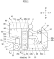
Figure 1 is a left side view schematically showing a fuel cell vehicle according to an embodiment. -
Figure 2 is a right side view schematically showing the fuel cell vehicle according to the embodiment. -
Figure 3 is a rear view schematically showing the fuel cell vehicle according to the embodiment. -
Figure 4 is a cross-sectional view schematically showing the fuel cell vehicle according to the embodiment in a state of being taken along a line W-W inFigure 1 . -
Figure 5 is a cross-sectional view schematically showing the fuel cell vehicle according to the embodiment in a state of being taken along a line X-X inFigure 1 . -
Figure 6 is a cross-sectional view schematically showing the fuel cell vehicle according to the embodiment in a state of being taken along a line Y-Y inFigure 3 . -
Figure 7 is a cross-sectional view schematically showing the fuel cell vehicle according to the embodiment in a state of being taken along a line Z-Z inFigure 3 . - A fuel cell vehicle according to an embodiment will be described below. The fuel cell vehicle according to the present embodiment is a fuel cell type vehicle for a single-seater type. In particular, the fuel cell vehicle may be a fuel cell type mobility vehicle for a single-seater type.
- However, the fuel cell vehicle is not limited to the above-described vehicle. For example, the fuel cell vehicle may be a fuel cell type vehicle for a double-seater type. In particular, the fuel cell vehicle may be a fuel cell type mobility vehicle for a double-seater type. In this case, two passengers preferably ride in the fuel cell vehicle side by side in a vehicle width direction.
- In
Figures 1 to 7 used for the description, directions based on the fuel cell vehicle (hereinafter, simply referred to as a "vehicle" as necessary) are indicated as follows. InFigures 1 ,2 ,6 , and7 , a front side and a rear side of the vehicle are indicated by a one-headed arrow F and a one-headed arrow B, respectively. InFigures 3 to 5 , a left side and a right side when viewed in the front side direction of the vehicle are indicated by a one-headed arrow L and a one-headed arrow R, respectively. A vehicle width direction is indicated by a one-headed arrow L and a one-headed arrow R. Furthermore, inFigures 1 to 7 , an upper side and a lower side of the vehicle are indicated by a one-headed arrow U and a one-headed arrow D, respectively. In the following description, directions simply referred to as "front side", "rear side", "left side", "right side", "upper side", "lower side", "front-rear direction", "width direction", and "up-down direction" indicate directions based on the vehicle. - An outline of the fuel cell vehicle according to the present embodiment will be described with reference to
Figures 1 to 7 . In other words, the fuel cell vehicle according to the present embodiment is schematically configured as follows. As shown inFigures 1 to 7 , a fuel cell vehicle includes avehicle body 1. - Referring to
Figures 1 and2 , the fuel cell vehicle includes anoperating part 10 including afront wheel 11 closer to the front side and anoperating device 12 used for a running operation. The fuel cell vehicle includes ariding part 20 configured to enable a passenger P to ride. Theriding part 20 is located closer to the rear side from theoperating part 10. - Referring to
Figures 1 to 3 , the fuel cell vehicle includes adrive part 30 located closer to the rear side from theriding part 20. Thedrive part 30 includes arear wheel 31 located closer to the rear side from thefront wheel 11. Thedrive part 30 includes adrive device 32 used for driving the vehicle to run. Thedrive device 32 includes amotor 33 configured to drive and move therear wheel 31. Thedrive device 32 includes amotor control device 34 configured to be able to control themotor 33. - Referring to
Figures 1 to 7 , the fuel cell vehicle includes afuel cell unit 40 configured to be capable of generating electric power used to drive themotor 33. The fuel cell vehicle includes afuel tank 50 configured to be capable of storing fuel used to generate electric power in thefuel cell unit 40. The fuel cell vehicle includes acompartment 60 that mounts thefuel cell unit 40 and thefuel tank 50. Thecompartment 60 is defined by ahousing 61. - Referring to
Figures 1 ,2 ,4 , and6 to 7 , the fuel cell vehicle includes a plurality offuel tanks 50. In these drawings, as an example, a fuel cell vehicle including threefuel tanks 50 is shown. However, the fuel cell vehicle may include two fuel tanks, or four or more fuel tanks. - As shown in
Figures 1 ,2 ,6 , and7 , thedrive part 30 includes afront edge region 30a located closer to the front side and anupper edge region 30b located closer to the upper side. Thecompartment 60 is disposed outside thedrive part 30 along the front edge andupper edge regions drive part 30. - Referring to
Figures 1 ,2 , and4 , thecompartment 60 includes anair inlet port 60a configured to allow air to flow thereinto. Theair inlet port 60a is disposed at a lower end of thecompartment 60. Referring toFigures 3 and5 to 7 , thecompartment 60 includes anexhaust port 62 configured to be able to discharge gas existing therein to the outside of thecompartment 60. Theexhaust port 62 is disposed at a rear end of thecompartment 60 located closer to the rear side from thedrive part 30. - Furthermore, the fuel cell vehicle according to the present embodiment can be schematically configured as follows. Referring to
Figures 1 ,2 ,4 ,6 , and7 , thecompartment 60 includes atank compartment 60b disposed along thefront edge region 30a of thedrive part 30. Thetank compartment 60b of thecompartment 60 is located closer to the front side from thedrive device 32. Thetank compartment 60b mounts thefuel tank 50. As shown inFigures 1 ,2 , and4 , theair inlet port 60a is disposed at a lower end of thetank compartment 60b of thecompartment 60. - Referring to
Figures 1 to 3 and5 to 7 , thecompartment 60 includes afuel cell compartment 60c disposed along theupper edge region 30b of thedrive part 30 toward the rear side from the upper end of thetank compartment 60b. Thefuel cell compartment 60c mounts thefuel cell unit 40. As shown inFigures 3 and5 to 7 , theexhaust port 62 is disposed at a rear end of thefuel cell compartment 60c of thecompartment 60 located closer to the rear side from thedrive part 30. - Referring to
Figures 1 to 3 , and5 to 7 , thefuel cell unit 40 includes afuel cell stack 41 configured to be capable of generating electric power used to drive themotor 33. The fuel cell vehicle includes adrain tank 71 configured to be capable of storing water produced in thefuel cell stack 41. The fuel cell vehicle also includes adrain pipe 72 extending between thefuel cell stack 41 and thedrain tank 71 such that the water produced in thefuel cell stack 41 is sent to thedrain tank 71. Thedrive part 30 includes thedrain tank 71. - As shown in
Figures 6 and7 , thefuel cell stack 41 of thefuel cell unit 40 is disposed in the upper portion of thefuel cell compartment 60c located closer to the upper side. As shown inFigures 3 and5 , thedrain tank 71 is located on one side of thedrive device 32 in the width direction. Thedrain tank 71 is located on one side of themotor 33 of thedrive device 32 in the width direction. Themotor control device 34 of thedrive device 32 is located on the other side of themotor 33 of thedrive device 32 in the width direction. - Referring to
Figures 4 to 7 , the fuel cell vehicle includes asecondary cell unit 81 configured to be able to be charged with the electric power generated by thefuel cell unit 40 and to supply the electric power to themotor 33. The fuel cell vehicle includes an electricpower adjusting unit 82 configured to be able to adjust the electric power to be supplied from thesecondary cell unit 81 to themotor 33. - The
secondary cell unit 81 and the electricpower adjusting unit 82 are disposed outside thecompartment 60 and above thecompartment 60. Furthermore, thesecondary cell unit 81 is disposed closer to the front side from the electricpower adjusting unit 82. - Referring to
Figures 1 to 7 , the fuel cell vehicle according to the present embodiment can be configured as follows in detail. As shown inFigures 1 to 3 and5 to 7 , the fuel cell vehicle includes adrain mechanism 70 configured to drain the water produced in thefuel cell stack 41 of thefuel cell unit 40. Thedrain mechanism 70 includes thedrain tank 71 and thedrain pipe 72. - Referring to
Figures 1 to 7 , the fuel cell vehicle includes an electricpower control part 80 located outside thecompartment 60 and above thecompartment 60. Thesecondary cell unit 81 and the electricpower adjusting unit 82 are placed on thehousing 61 of thecompartment 60 in the electricpower control part 80. - The operating
part 10 includes twofront wheels 11 spaced apart from each other in the width direction. In particular, referring toFigures 1 and2 , the operatingdevice 12 includes asteering unit 12a configured to be able to steer at least twofront wheels 11. Thesteering unit 12a is configured to be steerable by a hand of the passenger P on the ridingpart 20. - For example, the
steering unit 12a may be a steering wheel. However, the steering unit is not limited to a steering wheel. For example, the steering unit may be a steering wheel having two grips spaced apart from each other in the vehicle width direction. - In particular, referring to
Figure 1 , the operatingdevice 12 includes anaccelerator 12b used to adjust a running speed of the vehicle. Theaccelerator 12b is configured to be operable by a foot of the passenger P on the ridingpart 20. In particular, referring toFigure 2 , the operatingdevice 12 includes abrake 12c used for braking the vehicle. Thebrake 12c is configured to be operable by a foot of the passenger P on the ridingpart 20. - In particular, referring to
Figures 1 and2 , the ridingpart 20 includes aseat 21 configured such that the passenger P can be seated. Theseat 21 includes aseat cushion 21a that supports buttocks of the passenger P. A space is formed between the operatingpart 10 and theseat 21 of the ridingpart 20. A height of theseat cushion 21a is set such that the operatingdevice 12 can be operated in a state in which the passenger P is seated on theseat cushion 21a. Theseat 21 is adjacent to thehousing 61 of thecompartment 60 in the vehicle front-rear direction. - Referring to
Figures 1 to 3 and5 to 7 , thedrive part 30 can be configured in detail as follows. Thedrive part 30 includes tworear wheels 31 spaced apart from each other in the width direction. Themotor 33 is connected to the tworear wheels 31 to be able to drive the tworear wheels 31. Themotor 33, themotor control device 34, and thedrain tank 71 are disposed between the tworear wheels 31 in the width direction. - As shown in
Figures 1 ,2 ,6 , and7 , thefront edge region 30a of thedrive part 30 is defined along a front edge of thedrive part 30 located at the frontmost side in thedrive part 30 as viewed in the width direction. Theupper edge region 30b of thedrive part 30 is defined along an upper edge of thedrive part 30 located at the uppermost side in thedrive part 30 as viewed in the width direction. - Referring to
Figures 5 to 7 , thefuel cell unit 40 can be configured in detail as follows. In thefuel cell unit 40, thefuel cell stack 41 generates electric power using fuel supplied from thefuel tank 50. - The
fuel cell unit 40 includes thecompressor 42 configured to be able to send compressed air to thefuel cell stack 41. The air sent from thecompressor 42 to thefuel cell stack 41 is used for generation of electric power in thefuel cell stack 41. Thecompressor 42 includes theair intake port 42a configured to take air therein. Theair intake port 42a is opened forward such that air can be taken into thecompressor 42 from the front side to the rear side. Thecompressor 42 is located on one side of thefuel cell stack 41 in the width direction. - The
fuel cell unit 40 includes anexhaust fan 43 configured to send the gas discharged from thefuel cell stack 41 from thefuel cell stack 41 toward theexhaust port 62 in order to discharge the gas to the outside of thecompartment 60. Theexhaust fan 43 is located on the other side of thecompressor 42 in the width direction. Theexhaust fan 43 is located rearward of thefuel cell stack 41. - The
fuel cell unit 40 includes apower supply circuit 44 configured to be able to draw the electric power generated by thefuel cell stack 41. Thepower supply circuit 44 is located on the other side of theexhaust fan 43 in the width direction. The electric power drawn by thepower supply circuit 44 is supplied to themotor 33 to operate themotor 33 or an auxiliary machine, or is sent to adrive cell 81a or anauxiliary cell 81b to charge thedrive cell 81a or theauxiliary cell 81b of thesecondary cell unit 81. - Here, the auxiliary machine may be an electric device other than the
motor 33. Examples of the auxiliary machines may include electrical machines, for example, themotor control device 34, thecompressor 42, theexhaust fan 43, aventilation hole 68 to be described below, a secondarycell control device 83, amulti-control device 84, and other in-vehicle electrical components. - Referring to
Figures 1 ,2 ,4 ,6 , and7 , thefuel tank 50 can be configured in detail as follows. Thefuel tank 50 includes acontainer 51 configured to store the fuel. Thefuel tank 50 also includes a Shut-offvalve 52 attached to a neck of thecontainer 51. The Shut-offvalve 52 is configured to be able to open and close a flow of fuel between the inside and the outside of thecontainer 51. Such afuel tank 50 may be a portable high-pressure container. - In the plurality of
fuel tanks 50, the amount of opening and closing of the Shut-offvalve 52 can be adjusted. The plurality offuel tanks 50 are disposed such that the Shut-offvalve 52 is directed to one side in a width direction in thetank compartment 60b of thecompartment 60. The Shut-offvalves 52 of the plurality offuel tanks 50 face the same side in the width direction. Thecompressor 42 described above is located on a side of thefuel cell stack 41 facing the Shut-offvalve 52 in the width direction. - The plurality of
fuel tanks 50 are aligned in an up-down direction. The Shut-offvalves 52 of the plurality offuel tanks 50 are aligned in the up-down direction. The Shut-offvalves 52 of the plurality offuel tanks 50 are aligned on a vertical line. As shown inFigures 4 and6 , the fuel cell vehicle includes afuel supply pipe 53 extending such that the fuel flowing out of the Shut-offvalves 52 of the plurality offuel tanks 50 can be sent toward thefuel cell stack 41. Thefuel supply pipe 53 is connected to the Shut-offvalves 52 of the plurality offuel tanks 50 and thefuel cell stack 41. A flow rate of the fuel passing through thefuel supply pipe 53 can be adjusted. - Referring to
Figures 1 to 7 , thecompartment 60 can be configured in detail as follows. As shown inFigures 1 ,2 ,6 , and7 , thetank compartment 60b of thecompartment 60 is located between the ridingpart 20 and thedrive part 30 in the front-rear direction. Thefuel cell compartment 60c of thecompartment 60 is located closer to the rear side from thetank compartment 60b. Thefuel cell compartment 60c of thecompartment 60 is located above thedrive part 30. Thefuel cell compartment 60c is located closer to the upper side from thedrive device 32. Thetank compartment 60b and thefuel cell compartment 60c are adjacent to each other in the front-rear direction. - Referring to
Figures 1 to 7 , thehousing 61 of thecompartment 60 includes anintermediate housing part 61a that partitions thetank compartment 60b and thefuel cell compartment 60c from each other. Thehousing 61 includes a tank-side housing part 61b that defines thetank compartment 60b together with theintermediate housing part 61a. Thehousing 61 includes a fuel cell-side housing part 61c that defines thefuel cell compartment 60c together with theintermediate housing part 61a. - Referring to
Figures 1 to 5 , thecompartment 60 includesair inlet ducts compartment 60 includes twoair inlet ducts air inlet ducts tank compartment 60b of thecompartment 60 in the width direction, and are adjacent to thetank compartment 60b in the width direction. Thecompartment 60 includes at least one ventingport air inlet ducts tank compartment 60b. - Each of the
air inlet ducts air inlet ducts air inlet duct 63 of the twoair inlet ducts air inlet duct 63, and theair inlet duct 64 of the two air inlet ducts on the other side in the width direction is referred to as a secondair inlet duct 64. - Referring to
Figures 1 and4 , the firstair inlet duct 63 is located closer to one side in the width direction from the Shut-offvalves 52 of the plurality offuel tanks 50. The firstair inlet duct 63 is overlapped on these Shut-offvalves 52 as viewed in the width direction. The firstair inlet duct 63 extends from the lower side toward the upper side along the Shut-offvalves 52 of the plurality offuel tanks 50 aligned in the up-down direction. - The first
air inlet duct 63 includes anair inlet port 63a configured to be able to allow air to flow thereinto. Theair inlet port 63a is disposed at a lower end of the firstair inlet duct 63. Theair inlet port 63a corresponds to theair inlet port 60a of thecompartment 60 described above. Theair inlet port 63a is opened downward. However, the air inlet port can also be opened forward, rearward, or outward in the width direction. - The
compartment 60 includes a plurality of ventingports 63b through which the firstair inlet duct 63 and thetank compartment 60b vent (communicate) with each other. However, the compartment may include one venting port formed to vent the first air inlet duct with the tank compartment. In this case, one venting port may be disposed to correspond to the fuel tank located at the lowermost side among the plurality of fuel tanks. - The number of the plurality of venting
ports 63b corresponds to the number of the plurality offuel tanks 50. One of the plurality of ventingports 63b is disposed to correspond to thefuel tank 50 located at the lowermost side among the plurality offuel tanks 50. The plurality of ventingports 63b are disposed to face the Shut-offvalves 52 of the plurality offuel tanks 50, respectively. - Referring to
Figures 2 and4 , the secondair inlet duct 64 is located closer to the other side in the width direction from the plurality offuel tanks 50. The secondair inlet duct 64 extends from the lower side to the upper side along the plurality offuel tanks 50 aligned in the up-down direction. The secondair inlet duct 64 can be formed substantially symmetrically with the firstair inlet duct 63 in the width direction. - The second
air inlet duct 64 includes anair inlet port 64a configured to be able to allow air to flow thereinto. Theair inlet port 64a is disposed at a lower end of the secondair inlet duct 64. Theair inlet port 64a also corresponds to theair inlet port 60a of thecompartment 60 described above. Theair inlet port 64a is opened downward. However, the air inlet port can also be opened forward, rearward, or outward in the width direction. - The
compartment 60 includes one ventingport 64b formed to vent (communicate) the secondair inlet duct 64 with thetank compartment 60b. However, the compartment may include a plurality of venting ports formed to vent the second air inlet duct with the tank compartment. In this case, each of the plurality of venting ports may be disposed to face each of the plurality of fuel tanks. - One venting
port 64b is disposed to correspond to thefuel tank 50 located on the uppermost side among the plurality offuel tanks 50. However, one venting port may be disposed to correspond to the fuel tank other than the fuel tank located on the uppermost side among the plurality of fuel tanks. For example, one venting port may be disposed to correspond to the fuel tank located on the lowermost side among the plurality of fuel tanks. - As shown in
Figure 6 , thecompartment 60 includes theconnection port 65 that is opened to connect thetank compartment 60b and thefuel cell compartment 60c. Theconnection port 65 is directed rearward to face theair intake port 42a of thecompressor 42 of thefuel cell unit 40. An upper end of theconnection port 65 is located above the lower end of theair intake port 42a. - The
connection port 65 is formed to penetrate theintermediate housing part 61a. A peripheral edge of theconnection port 65 can be formed to protrude toward theair intake port 42a from theintermediate housing part 61a. Theconnection port 65 is disposed to be overlapped on theair intake port 42a as viewed in the front-rear direction. Theconnection port 65 can be disposed to be overlapped on theair intake port 42a as viewed in the front-rear direction as a whole. - Referring to
Figures 3 ,5 , and7 , theexhaust port 62 is formed to penetrate a rear end of the fuel cell-side housing part 61c in the front-rear direction. Theexhaust port 62 is disposed behind theexhaust fan 43 of thefuel cell unit 40. Theexhaust port 62 faces theexhaust fan 43 in the front-rear direction. - A peripheral edge of the
exhaust port 62 can be formed to protrude toward theexhaust fan 43 from the rear end of the fuel cell-side housing part 61c. Theexhaust port 62 is disposed to be overlapped on theexhaust fan 43 as viewed in the front-rear direction. Theexhaust port 62 can be disposed to be overlapped on theexhaust fan 43 as viewed in the front-rear direction as a whole. - Referring to
Figures 4 ,6 , and7 , thecompartment 60 includes aframe assembly 66 disposed to surround the plurality offuel tanks 50. Theframe assembly 66 includes a plurality oflongitudinal frames longitudinal frames frame assembly 66 includes a plurality oflateral frames lateral frames - The
frame assembly 66 is disposed in thetank compartment 60b. Theintermediate housing part 61a and the tank-side housing part 61b of thehousing 61 are supported by theframe assembly 66. Theintermediate housing part 61a and the tank-side housing part 61b of thehousing 61 are also attached to theframe assembly 66. - The plurality of
longitudinal frames longitudinal frame 66a located at one end in the width direction of theframe assembly 66. The plurality oflongitudinal frames longitudinal frame 66b located at the other end in the width direction of theframe assembly 66. The first and secondlongitudinal frames - The first
longitudinal frame 66a is located on the side facing the Shut-offvalve 52 in the width direction. The firstlongitudinal frame 66a is located between the Shut-offvalve 52 of thefuel tank 50 and the firstair inlet duct 63 as viewed in the front-rear direction. Theframe assembly 66 may include two firstlongitudinal frames 66a spaced apart from each other in the front-rear direction. The secondlongitudinal frame 66b is located between thecontainer 51 of thefuel tank 50 and the secondair inlet duct 64 as viewed in the front-rear direction. Theframe assembly 66 may include two secondlongitudinal frames 66b spaced apart from each other in the front-rear direction. - The plurality of
lateral frames lateral frames 66c connecting the first and secondlongitudinal frames lateral frames 66c is disposed in the width direction. The plurality of firstlateral frames 66c are spaced apart from each other in the up-down direction. - The plurality of
lateral frames lateral frames 66d connecting the two firstlongitudinal frames 66a. Each of the secondlateral frames 66d is disposed in the front-rear direction. The plurality oflateral frames lateral frames 66e connecting the two secondlongitudinal frames 66b. Each of the thirdlateral frames 66e is disposed in the front-rear direction. - Referring to
Figures 1 ,2 ,4 ,6 , and7 , the firstair inlet duct 63 is supported by the firstlongitudinal frame 66a. However, the firstair inlet duct 63 may also be supported by the secondlateral frame 66d instead of the firstlongitudinal frame 66a or in addition to the firstlongitudinal frame 66a. The secondair inlet duct 64 is supported by the secondlongitudinal frame 66b. However, the secondair inlet duct 64 may also be supported by the thirdlateral frame 66e instead of the secondlongitudinal frame 66b or in addition to the secondlongitudinal frame 66b. - Referring to
Figures 6 and7 , thecompartment 60 includes a fuelleakage detecting part 67 configured to be able to detect the fuel therein flowing out. The fuelleakage detecting part 67 is disposed in thefuel cell compartment 60c. In particular, the fuelleakage detecting part 67 can be disposed at an upper end and a rear end of thefuel cell compartment 60c. - Referring to
Figures 1 to 3 and5 , thecompartment 60 includes theventilation hole 68 configured to allow the fuel therein flowing out to be discharged to the outside of thecompartment 60. Theventilation hole 68 is configured to be openable and closable. The amount of opening and closing of theventilation hole 68 is adjustable. - The
ventilation hole 68 is also disposed in thefuel cell compartment 60c. In particular, theventilation hole 68 can be disposed in the fuel cell-side housing part 61c of thehousing 61. Furthermore, theventilation hole 68 can be disposed at an upper end and a rear end on a lateral surface in the width direction of the fuel cell-side housing part 61c. - The
ventilation hole 68 is normally in a closed state. Theventilation hole 68 is opened such that the fuel can be discharged to the outside of thecompartment 60 when the fuelleakage detecting part 67 detects the fuel flowing out into thefuel cell compartment 60c. - Referring to
Figure 7 , thedrain mechanism 70 can be configured in detail as follows. Thedrain pipe 72 of thedrain mechanism 70 extends downward from thefuel cell stack 41. Thedrain pipe 72 extends such that water generated in thefuel cell stack 41 can be sent from thefuel cell stack 41 to thedrain tank 71 by gravity. - The
drain pipe 72 includes an upstream end connected to a lower end of thefuel cell stack 41. Thedrain pipe 72 also includes a downstream end connected to an upper end of thedrain tank 71. Thedrain pipe 72 can be configured as a flexible hose. Thedrain pipe 72 can be configured to be detachably attached to thedrain tank 71. - The
drain tank 71 can be configured to be detachably attached to thevehicle body 1. In this case, the water stored in thedrain tank 71 can be drained in a state in which thedrain tank 71 is removed from thevehicle body 1. - Referring to
Figures 4 to 7 , the electricpower control part 80 can be configured in detail as follows. Thesecondary cell unit 81 of the electricpower control part 80 includes thedrive cell 81a that is a secondary cell configured as a main power source. Thedrive cell 81a can also be referred to as ahigh voltage cell 81a. Thesecondary cell unit 81 includes theauxiliary cell 81b that is a secondary cell configured as an auxiliary power source. Typically, theauxiliary cell 81b can be configured as a 12 V (volt) cell. - The electric
power adjusting unit 82 of the electricpower control part 80 includes a drive electricpower adjusting unit 82a configured to be able to adjust the electric power of thedrive cell 81a. The electricpower adjusting unit 82 includes an auxiliary electricpower adjusting unit 82b configured to be able to adjust electric power of theauxiliary cell 81b. The drive electricpower adjusting unit 82a can be configured as a DC/DC converter ("DC" being an abbreviation for "Direct Current") 82a for thedrive cell 81a. The auxiliary electricpower adjusting unit 82b can be configured as a DC/DC converter 82b for theauxiliary cell 81b. - The electric
power control part 80 includes the secondarycell control device 83 configured to be able to control charging and discharging of thesecondary cell unit 81. The secondarycell control device 83 is configured to be able to control the electricpower adjusting unit 82 and the drive electric power and auxiliary electricpower adjusting units - The electric
power control part 80 includes themulti-control device 84 configured to be able to execute several types of control, for example, drive control of the vehicle and control of thefuel cell unit 40. Themulti-control device 84 is configured to control the vehicle to drive in cooperation with themotor control device 34 and the secondarycell control device 83, based on an instruction from the operatingdevice 12. Themulti-control device 84 is configured to be able to control thefuel cell stack 41, thecompressor 42, and theexhaust fan 43 of thefuel cell unit 40. - The
multi-control device 84 can be configured to be able to control opening and closing of the Shut-offvalves 52 in the plurality offuel tanks 50. Themulti-control device 84 is configured to be able to close the Shut-offvalve 52 as necessary based on the detection of the fuelleakage detecting part 67. - The electric
power control part 80 includes acover 85 that defines the electricpower control part 80 together with the upper end surface of thehousing 61 of thecompartment 60. Thecover 85 is formed to surround the electricpower control part 80 from above. Thecover 85 is detachably attached to the upper end surface of thehousing 61 of thecompartment 60. - In a state in which the
cover 85 is removed from the upper end surface of thehousing 61, it is possible to easily replace thedrive cell 81a and theauxiliary cell 81b of thesecondary cell unit 81 opened to the outside of the vehicle. In the state in which thecover 85 is removed from the upper end surface of thehousing 61, it is possible to easily perform maintenance on thedrive cell 81a and theauxiliary cell 81b of thesecondary cell unit 81 opened to the outside of the vehicle, the drive electricpower adjusting unit 82a and the auxiliary electricpower adjusting unit 82b of the electricpower adjusting unit 82, the secondarycell control device 83, and themulti-control device 84. - The
drive cell 81a is disposed in front of theauxiliary cell 81b. Thedrive cell 81a is adjacent to theauxiliary cell 81b in the front-rear direction. The drive electricpower adjusting unit 82a and the auxiliary electricpower adjusting unit 82b are disposed rearward of theauxiliary cell 81b. The drive electricpower adjusting unit 82a and the auxiliary electricpower adjusting unit 82b are spaced apart from each other in the front-rear direction with respect to theauxiliary cell 81b. - The secondary
cell control device 83 is aligned with thesecondary cell unit 81 in the width direction. In particular, the secondarycell control device 83 can be aligned with thedrive cell 81a of thesecondary cell unit 81 in the width direction. Themulti-control device 84 is disposed rearward of the secondarycell control device 83. Themulti-control device 84 is aligned with the electricpower adjusting unit 82 in the width direction. In particular, themulti-control device 84 can be aligned with the drive electricpower adjusting unit 82a and the auxiliary electricpower adjusting unit 82b of the electricpower adjusting unit 82 in the width direction. - The fuel cell vehicle according to the present embodiment can perform the following functions. Here, as an example, a case will be described in which hydrogen fuel is used for a fuel cell vehicle. In the fuel cell vehicle, the
compartment 60 mounts a mechanism for supplying hydrogen fuel from thefuel tank 50 to thefuel cell unit 40 and a mechanism for generating power using thefuel cell unit 40. - The
air inlet ducts tank compartment 60b in the width direction of thecompartment 60, respectively. Theair inlet ducts air inlet ports air inlet ducts air inlet ports compartment 60 through the ventingports fuel cell unit 40 generates power using the air which has entered thecompartment 60 in this way. For this reason, theair inlet ducts fuel cell unit 40. - With respect to the shape of the
air inlet ducts air inlet ducts air inlet ports air inlet ducts ports compartment 60, the air supplied to thefuel cell unit 40 is sent from thecompressor 42 to thefuel cell stack 41 as air for reaction with hydrogen, and then the air is taken in from the front surface of thefuel cell stack 41 for the purpose of cooling thefuel cell stack 41 itself and further flows to be discharged from theexhaust port 62 by theexhaust fan 43 after the reaction or after cooling. - Normally, the inside of the
compartment 60 is in a state of weak negative pressure when thefuel cell unit 40 is operated, whereas the inside of thecompartment 60 is in a state of normal pressure when thefuel cell unit 40 is stopped. Such acompartment 60 mounts the pipe such as thefuel supply pipe 53 located around thefuel tank 50. When hydrogen leakage occurs from such a pipe during the operation of the fuel cell vehicle and exceeds the hydrogen concentration determined by the fuelleakage detecting part 67, the fuel cell vehicle functions to close the Shut-offvalve 52 of thefuel tank 50 and to stop the operation of thefuel cell unit 40. - After the
fuel cell unit 40 is stopped, the hydrogen in thecompartment 60 is gathered higher, and can be naturally discharged from theventilation hole 68 to the outside of thecompartment 60. A ceiling surface of thecompartment 60 may be preferably formed to be higher from the front side to the rear side, and theventilation hole 68 may be located in the vicinity of a rear end of the ceiling surface of thecompartment 60 which is highest. The fuelleakage detecting part 67 may be disposed in thecompartment 60 at a place where hydrogen can be easily detected. One fuelleakage detecting part 67 or a plurality of fuelleakage detecting parts 67 may be disposed in thecompartment 60. The fuelleakage detecting part 67 is also disposed near theventilation hole 68 to effectively detect hydrogen. - As described above, the fuel cell vehicle according to the present embodiment includes: the operating part 10 including the front wheel 11 located closer to the front side and the operating device 12 used for the running operation; the riding part 20 configured to be able to allow the passenger P to ride in and located closer to the rear side from the operating part 10; the drive part 30 including the rear wheel 31 located closer to the rear side from the front wheel 11, and the drive device 32, the drive device 32 including the motor 33 configured to be able to drive the rear wheel 31, and the motor control device 34 configured to be able to control the motor 33, the drive part 30 being located closer to the rear side from the riding part 20; the fuel cell unit 40 configured to be able to generate the electric power used to drive the motor 33; and the fuel tank 50 configured to be able to store the fuel used for the electric power generation in the fuel cell unit 40, wherein the fuel cell vehicle includes the compartment 60 for mounting the fuel cell unit 40 and the fuel tank 50, the compartment 60 being defined by the housing 61, the drive part 30 includes the front edge region 30a located closer to the front side and the upper edge region 30b located closer to the upper side, the compartment 60 is disposed along the front edge and upper edge regions 30a and 30b of the drive part 30 at the outside of the drive part 30, the compartment 60 includes the air inlet port 60a configured to be able to allow air to flow thereinto and the exhaust port 62 configured to be able to discharge the gas existing in the compartment 60 to the outside of the compartment 60, the air inlet port 60a is disposed at the lower end of the compartment 60, and the exhaust port 62 is disposed at the rear end of the compartment 60 located closer to the rear side from the drive part 30.
- In such a fuel cell vehicle, the
fuel cell unit 40 and thefuel tank 50 are separated from themotor 33 and themotor control device 34 by thehousing 61 of thecompartment 60. As a result, it is possible to prevent fuel such as hydrogen in thefuel cell unit 40 and thefuel tank 50 from coming into contact with electrical systems, for example, themotor 33 and themotor control device 34. Therefore, the fuel cell vehicle can be safely improved. - In particular, during the driving of the vehicle, the air passes through the inside of the
compartment 60 located around thedrive part 30 from theair inlet port 60a located at the lower end of thecompartment 60, and flows to reach theexhaust port 62 located at the rear end of thecompartment 60. As a result, it is possible to efficiently cool thefuel cell unit 40 in thecompartment 60 with the air flowing into the inside of thecompartment 60 in this way. Due to the temperature drop of thecompartment 60, it is also possible to cool themotor 33 and themotor control device 34 of thedrive part 30 adjacent to thecompartment 60. Therefore, it is possible to prevent performance deterioration of the fuel cell vehicle due to temperature increase. - In addition, the
compartment 60 is disposed along the front edge andupper edge regions drive part 30 so as to efficiently utilize a dead space around thedrive part 30. As a result, thefuel cell unit 40, thefuel tank 50, themotor 33, and themotor control device 34 can be disposed to be integrated in and around thedrive part 30. Therefore, the size of the fuel cell vehicle can be reduced. - In the fuel cell vehicle according to the present embodiment, the
compartment 60 includes thetank compartment 60b disposed along thefront edge region 30a of thedrive part 30 and thefuel cell compartment 60c disposed along theupper edge region 30b of thedrive part 30 from the upper end of thetank compartment 60b toward the rear side, thetank compartment 60b of thecompartment 60 is located closer to the front side from thedrive device 32 and mounts thefuel tank 50, thefuel cell compartment 60c of thecompartment 60 is located closer to the upper side from thedrive device 32 and mounts thefuel cell unit 40, theair inlet port 60a is disposed at the lower end of thetank compartment 60b of thecompartment 60, and theexhaust port 62 is disposed at the rear end of thefuel cell compartment 60c of thecompartment 60 located closer to the rear side from thedrive part 30. - In such a fuel cell vehicle, the
air inlet port 60a and theexhaust port 62 of thecompartment 60 can be sufficiently separated from each other. As a result, it is possible to prevent the air discharged from theexhaust port 62 in a state of being heated by thefuel cell unit 40 or the like from being taken into the inside of thecompartment 60 again from theair inlet port 60a. Therefore, it is possible to efficiently cool thefuel cell unit 40 in thecompartment 60, and to prevent performance deterioration of the fuel cell vehicle due to temperature increase. Since thefuel cell unit 40 and thefuel tank 50 can be efficiently disposed inside thecompartment 60 and themotor 33 and themotor control device 34 can be efficiently disposed in thedrive part 30 located outside thecompartment 60, the size of the fuel cell vehicle can be reduced. - In the fuel cell vehicle according to the present embodiment, the fuel cell vehicle includes the
drain tank 71 configured to be capable of storing water produced in thefuel cell stack 41 offuel cell unit 40 and thedrain pipe 72 extending between thefuel cell stack 41 and thedrain tank 71 such that the water produced in thefuel cell stack 41 is sent to thedrain tank 71, thedrive part 30 includes thedrain tank 71, thedrain tank 71 is located on one side in the width direction of thedrive device 32 in thedrive part 30, and thefuel cell stack 41 is disposed in the upper portion of thefuel cell compartment 60c located closer to the upper side. - In such a fuel cell vehicle, since the
drain tank 71, which tends to be large, can be efficiently disposed so as to efficiently utilize the dead space in thedrive part 30, the size of the fuel cell vehicle can be reduced. Since thedrain tank 71 is disposed below thefuel cell stack 41, the water produced in thefuel cell stack 41 can be efficiently sent to thedrain tank 71 while passing through thedrain pipe 72 using gravity. - Furthermore, since the
fuel cell stack 41 is disposed closer to the upper side of thefuel cell compartment 60c of thecompartment 60, a distance in the up-down direction between thefuel cell stack 41 and thedrain tank 71 is sufficiently maintained, and a water path from thefuel cell stack 41 toward thedrain tank 71 can be efficiently routed. - In the fuel cell vehicle according to the present embodiment, the
drain tank 71 is located on one side of themotor 33 of thedrive device 32 in the width direction, and themotor control device 34 of thedrive device 32 is located on the other side of themotor 33 of thedrive device 32 in the width direction. - In such a fuel cell vehicle, waterproof performance of the
motor control device 34 tends to be lower than waterproof performance of themotor 33. On the other hand, since themotor control device 34 is disposed to be separated from thedrain tank 71 by themotor 33, the water in thedrain tank 71 can be prevented from coming into contact with themotor control device 34. For example, even when water is produced due to dew condensation or the like and the water is delivered through thedrain pipe 72 such as a hose, themotor control device 34 can be prevented from being splashed with the water. Therefore, the fuel cell vehicle can have improved safety, and performance deterioration of the fuel cell vehicle can be prevented. - In the fuel cell vehicle according to the present embodiment, the fuel cell vehicle includes the
secondary cell unit 81 configured to be able to be charged with the electric power generated by thefuel cell unit 40 and to supply the electric power to themotor 33 and the electricpower adjusting unit 82 configured to be able to adjust the electric power to be supplied from thesecondary cell unit 81 to themotor 33, and thesecondary cell unit 81 and the electricpower adjusting unit 82 are disposed outside thecompartment 60 and above thecompartment 60. - In such a fuel cell vehicle, a maintenance frequency of the
secondary cell unit 81 such as replacement of thesecondary cell unit 81 and a maintenance frequency of the electricpower adjusting unit 82 related to thesecondary cell unit 81 are higher than maintenance frequencies of other components. On the other hand, since thesecondary cell unit 81 and the electricpower adjusting unit 82 are disposed outside thecompartment 60 and above thecompartment 60, it is possible to facilitate the maintenance of thesecondary cell unit 81 and the electricpower adjusting unit 82, and accordingly to prevent mistakes in maintenance of thesecondary cell unit 81 and the electricpower adjusting unit 82, which are frequently performed. - For example, the electric
power adjusting unit 82 can be kept away as far as possible from theexhaust port 62 even in a limited space. Furthermore, since thefuel cell unit 40 of which the temperature tends to increase is isolated from thesecondary cell unit 81 of which the temperature tends to increase similarly by thecompartment 60, it is possible to prevent the temperature of thefuel cell unit 40 and thesecondary cell unit 81 from rising synergistically. Therefore, the fuel cell vehicle can be of improved safety, and performance deterioration of the fuel cell vehicle can be prevented. - In the fuel cell vehicle according to the present embodiment, the
secondary cell unit 81 is disposed closer to the front side from the electricpower adjusting unit 82. - In such a fuel cell vehicle, the
secondary cell unit 81 is farther away from theexhaust port 62 than the electricpower adjusting unit 82. Therefore, even when the fuel leaks in thecompartment 60, the leaked fuel hardly flows to thesecondary cell unit 81 compared with the electricpower adjusting unit 82, and as a result, the fuel can be prevented from coming into contact with thesecondary cell unit 81. - Although the embodiment of the present invention has been described above, the present invention is not limited to the above-described embodiment.
-
- 10
- Operating part,
- 11
- Front wheel,
- 12
- Operating device
- 20
- Riding part
- 30
- Drive part,
- 30a
- Front edge region,
- 30b
- Upper edge region,
- 31
- Rear wheel,
- 32
- Drive device,
- 33
- Motor,
- 34
- Motor control device
- 40
- Fuel cell unit,
- 41
- Fuel cell stack
- 50
- Fuel tank
- 60
- Compartment,
- 60a
- Air inlet port,
- 60b
- Tank compartment,
- 60c
- Fuel cell compartment,
- 61
- Housing,
- 62
- Exhaust port
- 71
- Drain tank,
- 72
- Drain pipe
- 81
- Secondary cell unit,
- 82
- Electric power adjusting unit
- P
- Passenger
Claims (6)
- A fuel cell vehicle comprising:an operating part (10) including a front wheel (11) located closer to a front side of the vehicle and an operating device (12) used for a running operation;a riding part (20) configured to be able to allow a passenger (P) to ride in and located closer to a rear side of the vehicle from the operating part (10);a drive part (30) including a rear wheel (31) located closer to the rear side of the vehicle from the front wheel (11), and a drive device (32), the drive device (32) including a motor (33) configured to be able to drive the rear wheel (31), and a motor control device (34) configured to be able to control the motor (33), the drive part (30) being located closer to the rear side of the vehicle from the riding part (20);a fuel cell unit (40) configured to be able to generate electric power used to drive the motor (33); anda plurality of fuel tanks (50) configured to be able to store fuel used for electric power generation in the fuel cell unit (40), characterized in thatthe riding part (20) includes a seat (21) configured such that the passenger (P) can be seated,the fuel cell vehicle includes a compartment (60) for mounting the fuel cell unit (40) and the fuel tanks (50), the compartment (60) being defined by a housing (61), and the compartment (60) being located closer to the rear side of the vehicle from the seat (21) of the riding part (20),the drive part (30) includes a front edge region (30a) located closer to the front side of the vehicle and an upper edge region (30b) located closer to an upper side,the compartment (60) is disposed along the front edge and upper edge regions (30a, 30b) of the drive part (30) at an outside of the drive part (30),the compartment (60) includes an air inlet port (60a) configured to be able to allow air to flow thereinto and an exhaust port (62) configured to be able to discharge gas existing in the compartment (60) to an outside of the compartment (60),the air inlet port (60a) is disposed at a lower end of the compartment (60), andthe exhaust port (62) is disposed at a rear end of the compartment (60) located closer to the rear side of the vehicle from the drive part (30).
- The fuel cell vehicle according to claim 1, whereinthe compartment (60) includes a tank compartment (60b) disposed along the front edge region (30a) of the drive part (30) and a fuel cell compartment (60c) disposed along the upper edge region (30b) of the drive part (30) from an upper end of the tank compartment (60b) toward the rear side of the vehicle,the tank compartment (60b) of the compartment (60) is located closer to the front side of the vehicle from the drive device (32) and mounts the fuel tanks (50),the fuel cell compartment (60c) of the compartment (60) is located closer to the upper side from the drive device (32) and mounts the fuel cell unit (40),the air inlet port (60a) is disposed at a lower end of the tank compartment (60b) of the compartment (60), andthe exhaust port (62) is disposed at a rear end of the fuel cell compartment (60c) of the compartment (60) located closer to the rear side of the vehicle from the drive part (30).
- The fuel cell vehicle according to claim 1 or 2, whereinthe fuel cell vehicle includesa drain tank (71) configured to be able to store water produced in a fuel cell stack (41) of the fuel cell unit (40) anda drain pipe (72) extending between the fuel cell stack (41) and the drain tank (71) such that the water produced in the fuel cell stack (41) is sent to the drain tank (71),the drive part (30) includes the drain tank (71),the drain tank (71) is located on one side in a vehicle width direction of the drive device (32) in the drive part (30), andthe fuel cell stack (41) is disposed in an upper portion of the fuel cell compartment (60c) located closer to the upper side.
- The fuel cell vehicle according to claim 3, whereinthe drain tank (71) is located on one side of the motor (33) of the drive device (32) in the vehicle width direction, andthe motor control device (34) of the drive device (32) is located on the other side of the motor (33) of the drive device (32) in the vehicle width direction.
- The fuel cell vehicle according to any one of claims 1 to 4, whereinthe fuel cell vehicle includesa secondary cell unit (81) configured to be able to be charged with the electric power generated by the fuel cell unit (40) and to supply the electric power to the motor (33) andan electric power adjusting unit (82) configured to be able to adjust the electric power to be supplied from the secondary cell unit (81) to the motor (33), andthe secondary cell unit (81) and the electric power adjusting unit (82) are disposed outside the compartment (60) and above the compartment (60).
- The fuel cell vehicle according to claim 5, wherein
the secondary cell unit (81) is disposed closer to the front side of the vehicle from the electric power adjusting unit (82).
Applications Claiming Priority (1)
| Application Number | Priority Date | Filing Date | Title |
|---|---|---|---|
| JP2021002088A JP7590693B2 (en) | 2021-01-08 | 2021-01-08 | Fuel Cell Vehicles |
Publications (2)
| Publication Number | Publication Date |
|---|---|
| EP4026715A1 EP4026715A1 (en) | 2022-07-13 |
| EP4026715B1 true EP4026715B1 (en) | 2023-10-04 |
Family
ID=78844558
Family Applications (1)
| Application Number | Title | Priority Date | Filing Date |
|---|---|---|---|
| EP21213578.4A Active EP4026715B1 (en) | 2021-01-08 | 2021-12-10 | Fuel cell vehicle |
Country Status (2)
| Country | Link |
|---|---|
| EP (1) | EP4026715B1 (en) |
| JP (1) | JP7590693B2 (en) |
Citations (1)
| Publication number | Priority date | Publication date | Assignee | Title |
|---|---|---|---|---|
| EP1587727B1 (en) * | 2003-01-28 | 2007-05-09 | Club Car Inc. | Housing for vehicle power systems |
Family Cites Families (7)
| Publication number | Priority date | Publication date | Assignee | Title |
|---|---|---|---|---|
| JP4362343B2 (en) * | 2003-10-06 | 2009-11-11 | ヤマハ発動機株式会社 | Vehicle with fuel cell |
| JP4791103B2 (en) * | 2005-08-23 | 2011-10-12 | 本田技研工業株式会社 | Motorcycle equipped with a fuel cell |
| DE102005042938A1 (en) * | 2005-09-09 | 2007-03-22 | Still Gmbh | Mobile work machine with a pressurized tank |
| JP2008074200A (en) | 2006-09-20 | 2008-04-03 | Suzuki Motor Corp | Small electric vehicle with fuel cell |
| JP5035886B2 (en) * | 2007-03-30 | 2012-09-26 | 本田技研工業株式会社 | Saddle type fuel cell vehicle |
| JP5055080B2 (en) * | 2007-10-03 | 2012-10-24 | ヤマハ発動機株式会社 | vehicle |
| JP6191381B2 (en) * | 2013-10-17 | 2017-09-06 | スズキ株式会社 | Fuel cell motorcycle |
-
2021
- 2021-01-08 JP JP2021002088A patent/JP7590693B2/en active Active
- 2021-12-10 EP EP21213578.4A patent/EP4026715B1/en active Active
Patent Citations (1)
| Publication number | Priority date | Publication date | Assignee | Title |
|---|---|---|---|---|
| EP1587727B1 (en) * | 2003-01-28 | 2007-05-09 | Club Car Inc. | Housing for vehicle power systems |
Also Published As
| Publication number | Publication date |
|---|---|
| EP4026715A1 (en) | 2022-07-13 |
| JP7590693B2 (en) | 2024-11-27 |
| JP2022107251A (en) | 2022-07-21 |
Similar Documents
| Publication | Publication Date | Title |
|---|---|---|
| EP4026723B1 (en) | Fuel cell vehicle | |
| US9543598B2 (en) | Fuel cell-powered motorcycle | |
| JP5056957B2 (en) | Evaporative fuel processing equipment | |
| EP2253530B1 (en) | Scooter type motorcycle equipped with fuel cell system | |
| US11273717B2 (en) | Open cabin vehicle | |
| JP5237697B2 (en) | Fuel cell vehicle | |
| US20100300785A1 (en) | Fuel cell powered vehicle | |
| EP3225522B1 (en) | Saddle-ride type vehicle | |
| JP6331838B2 (en) | Fuel cell motorcycle | |
| US10322646B2 (en) | Fuel cell vehicle | |
| JP4855764B2 (en) | Fuel cell motorcycle | |
| JP4145084B2 (en) | Fuel cell vehicle | |
| JP6463318B2 (en) | Saddle riding | |
| EP4026715B1 (en) | Fuel cell vehicle | |
| JP6610198B2 (en) | Hydrogen detector for fuel cell vehicle | |
| JP6648518B2 (en) | Hydrogen dilution equipment for fuel cell vehicles | |
| JP6666771B2 (en) | Saddle type vehicle | |
| JP5407546B2 (en) | Fuel cell vehicle | |
| JP2023062516A (en) | Battery pack smoke exhaust structure | |
| JP6822065B2 (en) | Fuel cell device | |
| US20260084521A1 (en) | Work vehicle | |
| JP2025006682A (en) | Work vehicles | |
| US20170113568A1 (en) | Electric vehicle | |
| JP2017084546A (en) | Exhaust duct structure for fuel cell vehicles |
Legal Events
| Date | Code | Title | Description |
|---|---|---|---|
| PUAI | Public reference made under article 153(3) epc to a published international application that has entered the european phase |
Free format text: ORIGINAL CODE: 0009012 |
|
| STAA | Information on the status of an ep patent application or granted ep patent |
Free format text: STATUS: REQUEST FOR EXAMINATION WAS MADE |
|
| 17P | Request for examination filed |
Effective date: 20211210 |
|
| AK | Designated contracting states |
Kind code of ref document: A1 Designated state(s): AL AT BE BG CH CY CZ DE DK EE ES FI FR GB GR HR HU IE IS IT LI LT LU LV MC MK MT NL NO PL PT RO RS SE SI SK SM TR |
|
| GRAP | Despatch of communication of intention to grant a patent |
Free format text: ORIGINAL CODE: EPIDOSNIGR1 |
|
| STAA | Information on the status of an ep patent application or granted ep patent |
Free format text: STATUS: GRANT OF PATENT IS INTENDED |
|
| INTG | Intention to grant announced |
Effective date: 20230720 |
|
| GRAS | Grant fee paid |
Free format text: ORIGINAL CODE: EPIDOSNIGR3 |
|
| GRAA | (expected) grant |
Free format text: ORIGINAL CODE: 0009210 |
|
| STAA | Information on the status of an ep patent application or granted ep patent |
Free format text: STATUS: THE PATENT HAS BEEN GRANTED |
|
| AK | Designated contracting states |
Kind code of ref document: B1 Designated state(s): AL AT BE BG CH CY CZ DE DK EE ES FI FR GB GR HR HU IE IS IT LI LT LU LV MC MK MT NL NO PL PT RO RS SE SI SK SM TR |
|
| REG | Reference to a national code |
Ref country code: GB Ref legal event code: FG4D |
|
| REG | Reference to a national code |
Ref country code: CH Ref legal event code: EP |
|
| REG | Reference to a national code |
Ref country code: IE Ref legal event code: FG4D |
|
| REG | Reference to a national code |
Ref country code: DE Ref legal event code: R096 Ref document number: 602021005630 Country of ref document: DE |
|
| REG | Reference to a national code |
Ref country code: LT Ref legal event code: MG9D |
|
| REG | Reference to a national code |
Ref country code: NL Ref legal event code: MP Effective date: 20231004 |
|
| REG | Reference to a national code |
Ref country code: AT Ref legal event code: MK05 Ref document number: 1617428 Country of ref document: AT Kind code of ref document: T Effective date: 20231004 |
|
| PG25 | Lapsed in a contracting state [announced via postgrant information from national office to epo] |
Ref country code: NL Free format text: LAPSE BECAUSE OF FAILURE TO SUBMIT A TRANSLATION OF THE DESCRIPTION OR TO PAY THE FEE WITHIN THE PRESCRIBED TIME-LIMIT Effective date: 20231004 |
|
| PG25 | Lapsed in a contracting state [announced via postgrant information from national office to epo] |
Ref country code: GR Free format text: LAPSE BECAUSE OF FAILURE TO SUBMIT A TRANSLATION OF THE DESCRIPTION OR TO PAY THE FEE WITHIN THE PRESCRIBED TIME-LIMIT Effective date: 20240105 |
|
| PG25 | Lapsed in a contracting state [announced via postgrant information from national office to epo] |
Ref country code: IS Free format text: LAPSE BECAUSE OF FAILURE TO SUBMIT A TRANSLATION OF THE DESCRIPTION OR TO PAY THE FEE WITHIN THE PRESCRIBED TIME-LIMIT Effective date: 20240204 |
|
| PG25 | Lapsed in a contracting state [announced via postgrant information from national office to epo] |
Ref country code: LT Free format text: LAPSE BECAUSE OF FAILURE TO SUBMIT A TRANSLATION OF THE DESCRIPTION OR TO PAY THE FEE WITHIN THE PRESCRIBED TIME-LIMIT Effective date: 20231004 |
|
| PG25 | Lapsed in a contracting state [announced via postgrant information from national office to epo] |
Ref country code: AT Free format text: LAPSE BECAUSE OF FAILURE TO SUBMIT A TRANSLATION OF THE DESCRIPTION OR TO PAY THE FEE WITHIN THE PRESCRIBED TIME-LIMIT Effective date: 20231004 |
|
| PG25 | Lapsed in a contracting state [announced via postgrant information from national office to epo] |
Ref country code: ES Free format text: LAPSE BECAUSE OF FAILURE TO SUBMIT A TRANSLATION OF THE DESCRIPTION OR TO PAY THE FEE WITHIN THE PRESCRIBED TIME-LIMIT Effective date: 20231004 |
|
| PG25 | Lapsed in a contracting state [announced via postgrant information from national office to epo] |
Ref country code: LT Free format text: LAPSE BECAUSE OF FAILURE TO SUBMIT A TRANSLATION OF THE DESCRIPTION OR TO PAY THE FEE WITHIN THE PRESCRIBED TIME-LIMIT Effective date: 20231004 Ref country code: IS Free format text: LAPSE BECAUSE OF FAILURE TO SUBMIT A TRANSLATION OF THE DESCRIPTION OR TO PAY THE FEE WITHIN THE PRESCRIBED TIME-LIMIT Effective date: 20240204 Ref country code: GR Free format text: LAPSE BECAUSE OF FAILURE TO SUBMIT A TRANSLATION OF THE DESCRIPTION OR TO PAY THE FEE WITHIN THE PRESCRIBED TIME-LIMIT Effective date: 20240105 Ref country code: ES Free format text: LAPSE BECAUSE OF FAILURE TO SUBMIT A TRANSLATION OF THE DESCRIPTION OR TO PAY THE FEE WITHIN THE PRESCRIBED TIME-LIMIT Effective date: 20231004 Ref country code: BG Free format text: LAPSE BECAUSE OF FAILURE TO SUBMIT A TRANSLATION OF THE DESCRIPTION OR TO PAY THE FEE WITHIN THE PRESCRIBED TIME-LIMIT Effective date: 20240104 Ref country code: AT Free format text: LAPSE BECAUSE OF FAILURE TO SUBMIT A TRANSLATION OF THE DESCRIPTION OR TO PAY THE FEE WITHIN THE PRESCRIBED TIME-LIMIT Effective date: 20231004 Ref country code: PT Free format text: LAPSE BECAUSE OF FAILURE TO SUBMIT A TRANSLATION OF THE DESCRIPTION OR TO PAY THE FEE WITHIN THE PRESCRIBED TIME-LIMIT Effective date: 20240205 |
|
| PG25 | Lapsed in a contracting state [announced via postgrant information from national office to epo] |
Ref country code: SE Free format text: LAPSE BECAUSE OF FAILURE TO SUBMIT A TRANSLATION OF THE DESCRIPTION OR TO PAY THE FEE WITHIN THE PRESCRIBED TIME-LIMIT Effective date: 20231004 Ref country code: RS Free format text: LAPSE BECAUSE OF FAILURE TO SUBMIT A TRANSLATION OF THE DESCRIPTION OR TO PAY THE FEE WITHIN THE PRESCRIBED TIME-LIMIT Effective date: 20231004 Ref country code: PL Free format text: LAPSE BECAUSE OF FAILURE TO SUBMIT A TRANSLATION OF THE DESCRIPTION OR TO PAY THE FEE WITHIN THE PRESCRIBED TIME-LIMIT Effective date: 20231004 Ref country code: NO Free format text: LAPSE BECAUSE OF FAILURE TO SUBMIT A TRANSLATION OF THE DESCRIPTION OR TO PAY THE FEE WITHIN THE PRESCRIBED TIME-LIMIT Effective date: 20240104 Ref country code: LV Free format text: LAPSE BECAUSE OF FAILURE TO SUBMIT A TRANSLATION OF THE DESCRIPTION OR TO PAY THE FEE WITHIN THE PRESCRIBED TIME-LIMIT Effective date: 20231004 Ref country code: HR Free format text: LAPSE BECAUSE OF FAILURE TO SUBMIT A TRANSLATION OF THE DESCRIPTION OR TO PAY THE FEE WITHIN THE PRESCRIBED TIME-LIMIT Effective date: 20231004 |
|
| REG | Reference to a national code |
Ref country code: DE Ref legal event code: R097 Ref document number: 602021005630 Country of ref document: DE |
|
| PG25 | Lapsed in a contracting state [announced via postgrant information from national office to epo] |
Ref country code: DK Free format text: LAPSE BECAUSE OF FAILURE TO SUBMIT A TRANSLATION OF THE DESCRIPTION OR TO PAY THE FEE WITHIN THE PRESCRIBED TIME-LIMIT Effective date: 20231004 |
|
| PG25 | Lapsed in a contracting state [announced via postgrant information from national office to epo] |
Ref country code: CZ Free format text: LAPSE BECAUSE OF FAILURE TO SUBMIT A TRANSLATION OF THE DESCRIPTION OR TO PAY THE FEE WITHIN THE PRESCRIBED TIME-LIMIT Effective date: 20231004 |
|
| PG25 | Lapsed in a contracting state [announced via postgrant information from national office to epo] |
Ref country code: SK Free format text: LAPSE BECAUSE OF FAILURE TO SUBMIT A TRANSLATION OF THE DESCRIPTION OR TO PAY THE FEE WITHIN THE PRESCRIBED TIME-LIMIT Effective date: 20231004 |
|
| PG25 | Lapsed in a contracting state [announced via postgrant information from national office to epo] |
Ref country code: SM Free format text: LAPSE BECAUSE OF FAILURE TO SUBMIT A TRANSLATION OF THE DESCRIPTION OR TO PAY THE FEE WITHIN THE PRESCRIBED TIME-LIMIT Effective date: 20231004 Ref country code: SK Free format text: LAPSE BECAUSE OF FAILURE TO SUBMIT A TRANSLATION OF THE DESCRIPTION OR TO PAY THE FEE WITHIN THE PRESCRIBED TIME-LIMIT Effective date: 20231004 Ref country code: RO Free format text: LAPSE BECAUSE OF FAILURE TO SUBMIT A TRANSLATION OF THE DESCRIPTION OR TO PAY THE FEE WITHIN THE PRESCRIBED TIME-LIMIT Effective date: 20231004 Ref country code: IT Free format text: LAPSE BECAUSE OF FAILURE TO SUBMIT A TRANSLATION OF THE DESCRIPTION OR TO PAY THE FEE WITHIN THE PRESCRIBED TIME-LIMIT Effective date: 20231004 Ref country code: EE Free format text: LAPSE BECAUSE OF FAILURE TO SUBMIT A TRANSLATION OF THE DESCRIPTION OR TO PAY THE FEE WITHIN THE PRESCRIBED TIME-LIMIT Effective date: 20231004 Ref country code: DK Free format text: LAPSE BECAUSE OF FAILURE TO SUBMIT A TRANSLATION OF THE DESCRIPTION OR TO PAY THE FEE WITHIN THE PRESCRIBED TIME-LIMIT Effective date: 20231004 Ref country code: CZ Free format text: LAPSE BECAUSE OF FAILURE TO SUBMIT A TRANSLATION OF THE DESCRIPTION OR TO PAY THE FEE WITHIN THE PRESCRIBED TIME-LIMIT Effective date: 20231004 |
|
| PLBE | No opposition filed within time limit |
Free format text: ORIGINAL CODE: 0009261 |
|
| STAA | Information on the status of an ep patent application or granted ep patent |
Free format text: STATUS: NO OPPOSITION FILED WITHIN TIME LIMIT |
|
| PG25 | Lapsed in a contracting state [announced via postgrant information from national office to epo] |
Ref country code: LU Free format text: LAPSE BECAUSE OF NON-PAYMENT OF DUE FEES Effective date: 20231210 |
|
| PG25 | Lapsed in a contracting state [announced via postgrant information from national office to epo] |
Ref country code: MC Free format text: LAPSE BECAUSE OF FAILURE TO SUBMIT A TRANSLATION OF THE DESCRIPTION OR TO PAY THE FEE WITHIN THE PRESCRIBED TIME-LIMIT Effective date: 20231004 |
|
| REG | Reference to a national code |
Ref country code: BE Ref legal event code: MM Effective date: 20231231 |
|
| PG25 | Lapsed in a contracting state [announced via postgrant information from national office to epo] |
Ref country code: MC Free format text: LAPSE BECAUSE OF FAILURE TO SUBMIT A TRANSLATION OF THE DESCRIPTION OR TO PAY THE FEE WITHIN THE PRESCRIBED TIME-LIMIT Effective date: 20231004 Ref country code: LU Free format text: LAPSE BECAUSE OF NON-PAYMENT OF DUE FEES Effective date: 20231210 |
|
| 26N | No opposition filed |
Effective date: 20240705 |
|
| REG | Reference to a national code |
Ref country code: IE Ref legal event code: MM4A |
|
| PG25 | Lapsed in a contracting state [announced via postgrant information from national office to epo] |
Ref country code: IE Free format text: LAPSE BECAUSE OF NON-PAYMENT OF DUE FEES Effective date: 20231210 |
|
| PG25 | Lapsed in a contracting state [announced via postgrant information from national office to epo] |
Ref country code: BE Free format text: LAPSE BECAUSE OF NON-PAYMENT OF DUE FEES Effective date: 20231231 |
|
| PG25 | Lapsed in a contracting state [announced via postgrant information from national office to epo] |
Ref country code: SI Free format text: LAPSE BECAUSE OF FAILURE TO SUBMIT A TRANSLATION OF THE DESCRIPTION OR TO PAY THE FEE WITHIN THE PRESCRIBED TIME-LIMIT Effective date: 20231004 |
|
| PG25 | Lapsed in a contracting state [announced via postgrant information from national office to epo] |
Ref country code: SI Free format text: LAPSE BECAUSE OF FAILURE TO SUBMIT A TRANSLATION OF THE DESCRIPTION OR TO PAY THE FEE WITHIN THE PRESCRIBED TIME-LIMIT Effective date: 20231004 Ref country code: IE Free format text: LAPSE BECAUSE OF NON-PAYMENT OF DUE FEES Effective date: 20231210 Ref country code: BE Free format text: LAPSE BECAUSE OF NON-PAYMENT OF DUE FEES Effective date: 20231231 |
|
| PG25 | Lapsed in a contracting state [announced via postgrant information from national office to epo] |
Ref country code: FI Free format text: LAPSE BECAUSE OF FAILURE TO SUBMIT A TRANSLATION OF THE DESCRIPTION OR TO PAY THE FEE WITHIN THE PRESCRIBED TIME-LIMIT Effective date: 20231004 |
|
| PG25 | Lapsed in a contracting state [announced via postgrant information from national office to epo] |
Ref country code: CY Free format text: LAPSE BECAUSE OF FAILURE TO SUBMIT A TRANSLATION OF THE DESCRIPTION OR TO PAY THE FEE WITHIN THE PRESCRIBED TIME-LIMIT; INVALID AB INITIO Effective date: 20211210 |
|
| REG | Reference to a national code |
Ref country code: CH Ref legal event code: PL |
|
| PG25 | Lapsed in a contracting state [announced via postgrant information from national office to epo] |
Ref country code: CH Free format text: LAPSE BECAUSE OF NON-PAYMENT OF DUE FEES Effective date: 20241231 |
|
| PG25 | Lapsed in a contracting state [announced via postgrant information from national office to epo] |
Ref country code: TR Free format text: LAPSE BECAUSE OF FAILURE TO SUBMIT A TRANSLATION OF THE DESCRIPTION OR TO PAY THE FEE WITHIN THE PRESCRIBED TIME-LIMIT Effective date: 20231004 |
|
| PGFP | Annual fee paid to national office [announced via postgrant information from national office to epo] |
Ref country code: DE Payment date: 20251028 Year of fee payment: 5 |
|
| PGFP | Annual fee paid to national office [announced via postgrant information from national office to epo] |
Ref country code: FR Payment date: 20251110 Year of fee payment: 5 |