EP4026445A1 - Aerosol generating device, heating assembly and data exchange method - Google Patents
Aerosol generating device, heating assembly and data exchange method Download PDFInfo
- Publication number
- EP4026445A1 EP4026445A1 EP20861068.3A EP20861068A EP4026445A1 EP 4026445 A1 EP4026445 A1 EP 4026445A1 EP 20861068 A EP20861068 A EP 20861068A EP 4026445 A1 EP4026445 A1 EP 4026445A1
- Authority
- EP
- European Patent Office
- Prior art keywords
- heat generating
- main body
- identification information
- server
- assembly
- Prior art date
- Legal status (The legal status is an assumption and is not a legal conclusion. Google has not performed a legal analysis and makes no representation as to the accuracy of the status listed.)
- Granted
Links
Images


Classifications
-
- A—HUMAN NECESSITIES
- A24—TOBACCO; CIGARS; CIGARETTES; SIMULATED SMOKING DEVICES; SMOKERS' REQUISITES
- A24F—SMOKERS' REQUISITES; MATCH BOXES; SIMULATED SMOKING DEVICES
- A24F40/00—Electrically operated smoking devices; Component parts thereof; Manufacture thereof; Maintenance or testing thereof; Charging means specially adapted therefor
- A24F40/60—Devices with integrated user interfaces
-
- A—HUMAN NECESSITIES
- A24—TOBACCO; CIGARS; CIGARETTES; SIMULATED SMOKING DEVICES; SMOKERS' REQUISITES
- A24F—SMOKERS' REQUISITES; MATCH BOXES; SIMULATED SMOKING DEVICES
- A24F40/00—Electrically operated smoking devices; Component parts thereof; Manufacture thereof; Maintenance or testing thereof; Charging means specially adapted therefor
- A24F40/50—Control or monitoring
- A24F40/57—Temperature control
-
- A—HUMAN NECESSITIES
- A24—TOBACCO; CIGARS; CIGARETTES; SIMULATED SMOKING DEVICES; SMOKERS' REQUISITES
- A24F—SMOKERS' REQUISITES; MATCH BOXES; SIMULATED SMOKING DEVICES
- A24F40/00—Electrically operated smoking devices; Component parts thereof; Manufacture thereof; Maintenance or testing thereof; Charging means specially adapted therefor
- A24F40/40—Constructional details, e.g. connection of cartridges and battery parts
- A24F40/46—Shape or structure of electric heating means
-
- A—HUMAN NECESSITIES
- A24—TOBACCO; CIGARS; CIGARETTES; SIMULATED SMOKING DEVICES; SMOKERS' REQUISITES
- A24F—SMOKERS' REQUISITES; MATCH BOXES; SIMULATED SMOKING DEVICES
- A24F40/00—Electrically operated smoking devices; Component parts thereof; Manufacture thereof; Maintenance or testing thereof; Charging means specially adapted therefor
- A24F40/50—Control or monitoring
-
- A—HUMAN NECESSITIES
- A24—TOBACCO; CIGARS; CIGARETTES; SIMULATED SMOKING DEVICES; SMOKERS' REQUISITES
- A24F—SMOKERS' REQUISITES; MATCH BOXES; SIMULATED SMOKING DEVICES
- A24F40/00—Electrically operated smoking devices; Component parts thereof; Manufacture thereof; Maintenance or testing thereof; Charging means specially adapted therefor
- A24F40/50—Control or monitoring
- A24F40/53—Monitoring, e.g. fault detection
-
- A—HUMAN NECESSITIES
- A24—TOBACCO; CIGARS; CIGARETTES; SIMULATED SMOKING DEVICES; SMOKERS' REQUISITES
- A24F—SMOKERS' REQUISITES; MATCH BOXES; SIMULATED SMOKING DEVICES
- A24F40/00—Electrically operated smoking devices; Component parts thereof; Manufacture thereof; Maintenance or testing thereof; Charging means specially adapted therefor
- A24F40/65—Devices with integrated communication means, e.g. wireless communication means
-
- G—PHYSICS
- G06—COMPUTING OR CALCULATING; COUNTING
- G06F—ELECTRIC DIGITAL DATA PROCESSING
- G06F16/00—Information retrieval; Database structures therefor; File system structures therefor
- G06F16/30—Information retrieval; Database structures therefor; File system structures therefor of unstructured textual data
- G06F16/38—Retrieval characterised by using metadata, e.g. metadata not derived from the content or metadata generated manually
- G06F16/381—Retrieval characterised by using metadata, e.g. metadata not derived from the content or metadata generated manually using identifiers, e.g. barcodes, RFIDs
-
- A—HUMAN NECESSITIES
- A24—TOBACCO; CIGARS; CIGARETTES; SIMULATED SMOKING DEVICES; SMOKERS' REQUISITES
- A24F—SMOKERS' REQUISITES; MATCH BOXES; SIMULATED SMOKING DEVICES
- A24F40/00—Electrically operated smoking devices; Component parts thereof; Manufacture thereof; Maintenance or testing thereof; Charging means specially adapted therefor
- A24F40/20—Devices using solid inhalable precursors
-
- A—HUMAN NECESSITIES
- A24—TOBACCO; CIGARS; CIGARETTES; SIMULATED SMOKING DEVICES; SMOKERS' REQUISITES
- A24F—SMOKERS' REQUISITES; MATCH BOXES; SIMULATED SMOKING DEVICES
- A24F47/00—Smokers' requisites not otherwise provided for
-
- G—PHYSICS
- G06—COMPUTING OR CALCULATING; COUNTING
- G06F—ELECTRIC DIGITAL DATA PROCESSING
- G06F2209/00—Indexing scheme relating to G06F9/00
- G06F2209/54—Indexing scheme relating to G06F9/54
- G06F2209/541—Client-server
Definitions
- the present disclosure relates to the field of display technologies, and in particular to an aerosol generating device, a heat generating assembly, and a data exchange method.
- An existing heated non-combustible aerosol generating device conventionally applies a heating element to heat an aerosol generating substrate to form a continuous smoking effect for a user to inhale. After the inhalation is completed, the user pulls the aerosol generating substrate out of the heating element to realize the separation of the heating element and the aerosol generating substrate.
- the aerosol generating substrate may produce a certain amount of adhesive attached to the heating element after heating, forming a bonded state, and the adhesive will remain on the surface of the heating element to accumulate further, resulting in a certain degree of increase in the outer diameter of the heating element, which causes the loss of the heating element loss, thereby affecting the taste of fuming products and reducing the life of the heated non-combustible aerosol generating device.
- the present disclosure provides an aerosol generating device, a heat generating assembly, and a data exchange method to solve the problem of the related art in which heating elements cannot be easily replaced.
- an aerosol generating device including: a main body; and a heat generating assembly, detachably connected to the main body; wherein the heat generating assembly includes first identification information, and the first identification information is configured to be identified by a server; the main body is configured to obtain characteristic parameters provided by the server according to the first identification information and to heat the heat generating assembly according to the characteristic parameters, for further heating an aerosol generating substrate with the heat generating assembly to generate aerosol; the characteristic parameters correspond to a type of the heat generating assembly.
- the main body establishes a data connection with an external terminal
- the heat generating assembly is configured to send the first identification information to the server through the external terminal
- the main body is further configured to obtain the characteristic parameters obtained by the server according to the first identification information from the server through the external terminal.
- the first identification information is a serial number; the characteristic parameters stored in the server are generated according to the first identification information, and the main body is configured to obtain, through the external terminal, the characteristic parameters generated by the server according to the serial number.
- the first identification information is a barcode
- the main body is configured to obtain, through the external terminal, the characteristic parameters generated by the server identifying the barcode.
- the first identification information is a two-dimensional code; the main body is configured to obtain, through the external terminal, the characteristic parameters generated by the server identifying the two-dimensional code.
- the first identification information is RFID tag information
- the server is configured to obtain the RFID tag information and generate the characteristic parameters through a RFID identifier.
- the main body includes a communication module, and the main body is configured to perform data interaction with the external terminal through the communication module.
- the communication module is one or more of a WIFI communication module, a Bluetooth communication module, or a near field communication (NFC) communication module.
- a WIFI communication module a Bluetooth communication module
- NFC near field communication
- the communication module is a data interface performing data interaction with the external terminal through a data line.
- the main body further includes: a housing assembly; and a controller, arranged in the housing assembly; wherein the heat generating assembly is detachably connected to the housing assembly; when connected with the housing assembly, the heat generating assembly is electrically connected with the controller; the controller is configured to obtain, through the communication module, the characteristic parameters from the server.
- the main body includes a first main body portion and a second main body portion; the first main body portion is configured to accommodate a battery, and the second main body portion is configured to connect with the heat generating assembly.
- the second main body portion is arranged with a first connector and the heat generating assembly is arranged with a second connector, for connecting the second body portion and the heat generating assembly.
- the aerosol generating device further includes a first cover detachably connected to the main body; when the heat generating assembly is connected to the main body, the first cover is sleeved on the heat generating assembly.
- the aerosol generating device further includes a second cover detachably connected to the main body; the second cover is sleeved on the heat generating assembly and the second main body portion; or, the second cover is sleeved on the first cover and the second main body portion.
- the main body includes second identification information; the second identification information is configured to be identified by the server; the main body is configured to obtain basic parameters generated by the server according to the second identification information, and update and/or upgrade according to the basic parameters.
- the heat generating assembly further includes: a heat generating body; and a first conductive terminal, connected to the heat generating body; wherein the main body includes a second conductive terminal; when the first conductive terminal and the second conductive terminal are connected, the main body is configured to supply power to the heat generating body; the characteristic parameters include heat generating body parameters and heating parameters in the heat generating assembly; the heat generating body parameters represent a corresponding relationship between a resistance value and a temperature of the heat generating body of the heat generating assembly; the main body is further configured to detect the resistance value of the heat generating body, determine the temperature of the heat generating body according to the heat generating body parameters, and heat the heat generating assembly according to the temperature of the heat generating body and the heating parameters.
- the main body is configured to control the temperature of the heat generating body by changing a pulse frequency and/or a pulse amplitude and/or a duty cycle of power supplied to the heat generating body.
- another technical solution adopted by the present disclosure is to provide a heat generating assembly, detachably connected to a main body of an aerosol generating device; wherein the heat generating assembly includes first identification information, and the first identification information is configured to be identified by a server; the main body is configured to obtain characteristic parameters provided by the server according to the first identification information and to heat the heat generating assembly according to the characteristic parameters, for further heating an aerosol generating substrate with the heat generating assembly to generate aerosol; the characteristic parameters correspond to a type of the heat generating assembly.
- the heat generating assembly further includes: a heat generating body; and a first conductive terminal, connected to the heat generating body; wherein the first conductive terminal is configured to be connected to a second conductive terminal of the main body for the main body supplying power to the heat generating body.
- another technical solution adopted by the present disclosure is to provide a data interaction method, applied to an external terminal; wherein the external terminal is configured to perform data interaction with an aerosol generating device and a server; the data interaction method includes: obtaining first identification information of a heat generating assembly in the aerosol generating device; sending the first identification information to the server; obtaining characteristic parameters provided by the server according to the first identification information; and sending the characteristic parameters to a main body in the aerosol generating device, such that the main body heats the heat generating assembly according to the characteristic parameters for further heating the aerosol generating substrate with the heat generating assembly to generate aerosol.
- the present disclosure provides an aerosol generating device including a main body; and a heat generating assembly detachably connected to the main body.
- the heat generating assembly includes first identification information, the first identification information may be configured to be identified by a server.
- the main body is configured to obtain characteristic parameters provided by the server according to the first identification information and to heat the heat generating assembly according to the characteristic parameters for further heating the aerosol generating substrate with the heat generating assembly to generate aerosol.
- the characteristic parameters correspond to a type of the heat generating assembly.
- the parts of the aerosol generating device can be replaced at will, reducing the cost of use; and on the other hand, ensuring that when the parts are replaced, they are not replaced with counterfeit parts, which affect the user's use.
- the characteristic parameters are protected in the server, reducing the cost of storage media and facilitating the real-time update of the product.
- FIG. 1 is a structural schematic view of an aerosol generating device according to an embodiment of the present disclosure
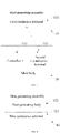
- FIG. 2 is a schematic view of data interaction between an aerosol generating device and a server according to an embodiment of the present disclosure
- FIG. 3 is a structural schematic view of an aerosol generating device according to another embodiment of the present disclosure.
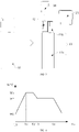
- the left half of FIG. 3 shows an overall schematic view of the aerosol generating device 10, and the right half shows a disassembly schematic view thereof.
- the aerosol generating device 10 includes a main body 11 and a heat generating assembly 12.
- the main body 11 and the heat generating assembly 12 are detachably connected.
- the heat generating assembly 12 includes first identification information, and the first identification information may be configured to be identified by a server 20.
- the main body 11 is configured to obtain characteristic parameters provided by the server 20 according to the first identification information and to heat the heat generating assembly according to the characteristic parameters for further heating the aerosol generating substrate with the heat generating assembly to generate aerosol.
- the characteristic parameters correspond to a type of the heat generating assembly.
- the characteristic parameters are formed according to different types of heat generating assemblies 12. Due to the influence of factors such as the material, process, and manufacturing device of a heating body in the heat generating assemblies 12, its characteristic parameters (such as "temperature T-resistance R" curve, initial resistance value R0, temperature coefficient of resistance (TCR), etc.) are different. During product production, the heat generating assembly 12 is placed in a testing device to test the characteristic parameters of the heat generating assembly 12 of different types.
- the server 20 stores a characteristic parameter-first identification information data packet. After the server 20 obtains the first identification information, the server 20 may unlock the characteristic parameter-first identification information data packet through the first identification information to generate corresponding characteristic parameters and provide to the main body 11.
- the server 20 stores a corresponding algorithm. After the first identification information is input, the characteristic parameters are obtained through the algorithm and provided to the main body 11.
- the first identification information may be the unique identification information of each heat generating assembly 12 or the unique identification information of the heat generating assemblies 12 of the same type. Therefore, the characteristic parameters obtained according to the first identification information may correspond to a unique heat generating assembly 12.
- the characteristic parameters correspond to heat generating assembly 12 of a type. Since the characteristic parameters are fixed, only the said characteristic parameters can be applied to heat the adapted heat generating assembly 12. When the type of the connected heat generating assembly 12 does not correspond to the type corresponding to the characteristic parameters, the heat generating assembly 12 may not heat the aerosol generating substrate well and the aerosol inhalation taste will become poor. In this way, it is possible to prevent changing the type of the heat generating assembly 12 at will. When the user replaces the heat generating assembly 12, only the heat generating assembly 12 of the same type can be replaced.
- the main body 11 specifically includes a first main body portion 11a and a second main body portion 11b.
- the first main body portion 11a is configured to accommodate a battery
- the second main body portion 11b is configured to accommodate a controller, etc. and to connect with the heat generating assembly 12.
- the second main body portion 11b is arranged with a first connector
- the heat generating assembly 12 is arranged with a second connector for connecting the second body portion 11b and the heat generating assembly 12.
- the first and second connector may be a buckle, a screw, or the like.
- the heat generating assembly 12 may also be connected to the first main body portion 11a through a bottom.
- the aerosol generating device 10 further includes a first cover 14 and a second cover 15 that are detachably connected to the main body 11.
- the first cover 14 may be sleeved on the heat generating assembly 12 to protect the heat generating assembly 12; further, the second cover 15 may be sleeved on the heat generating assembly 12 (or the first cover 14) and the second main body portion 11b for protecting the heat generating assembly 12 and the second main body portion 11b.
- the characteristic parameters include heat generating body parameters and heating parameters in the heat generating assembly 12.
- the heat generating body parameters represent a corresponding relationship between the resistance value and the temperature of the heat generating body.
- the heat generating body parameters are formed according to different types of heat generating assemblies 12. Due to the influence of factors such as the material, process, and manufacturing device of a heat generating body in the heat generating assembly 12, its characteristic parameters (such as "temperature T-resistance R" curve, initial resistance value R0, temperature coefficient of resistance (TCR), etc.) are different. During product production, the heat generating assembly 12 is placed in a testing device to test the characteristic parameters of the heat generating assembly 12 of different types.
- the heating parameter may specifically be a "temperature-time variation curve" to determine that the heat generating body is heated to different degrees over time. As shown in FIG. 4 ,
- FIG. 4 is a schematic view of a temperature-time change curve according to an embodiment of the present disclosure.
- the controller may control the temperature of the heat generating body according to a preset temperature-time curve with a PID algorithm.
- the "temperature-time" curve refers to the heating curve for tobacco.
- the electronic cigarette When a user uses the electronic cigarette to smoke, he/she may connect the main body 11 and the heat generating assembly 12, and alternatively turn on a switch button arranged on the main body 11. At this time, the electronic cigarette starts to work.
- the main body 11 obtains the characteristic parameters in the server 20, obtains the corresponding relationship between the resistance value and the temperature of the heat generating body in the heat generating assembly 12, and starts timing. Then the main body 11 obtains the current resistance value of the heat generating body, obtains the current temperature of the heat generating body based on the heat generating body parameters, and controls the voltage of the heat generating body through the "temperature-time" curve.
- the required heating temperature is different in different time periods.
- the abscissa represents time
- the ordinate represents temperature.
- the heat generating body is heated to increase its temperature from normal temperature W0 to temperature W1.
- the temperature of the heat generating body is kept at W1.
- the temperature of the heat generating body is decreased from W1 to temperature W2.
- the temperature of the heat generating body is kept at W2.
- the temperature of the heat generating body is decreased from W2 to normal temperature.
- the value of T1 may be 5-10s
- the value of T2 may be 12-18s
- the value of W1 may be 320-360°C
- the value of W2 may be 300-340°C.
- T1 7s
- T2 15s
- W1 340°C
- W2 320°C.
- methods may include changing the pulse frequency and/or pulse amplitude and/or duty cycle of the power supplied to the heat generating body to provide temperature control of the heat generating body, such that the aerosol device may be controlled to release smoke with a better taste.
- FIG. 5 is a schematic view of a pulse voltage according to an embodiment of the present disclosure.
- the temperature of the heat generating body can be adjusted by adjusting the percentage of tl in the period T. Specifically, increasing the duty ratio of tl, the temperature of the heat generating body increases, and decreasing the duty ratio of tl, the temperature of the heat generating body decreases.
- the main body 11 and the heat generating assembly 12 may be sold as a whole, and one or two of the main body 11 and the heat generating assembly 12 may be sold in combination, which can facilitate the user to replace any of the components.
- the user may purchase the main body 11 and the heat generating assembly 12 at the same time when purchasing for the first time.
- the heat generating assembly 12 is worn out and required to be replaced, only the heat generating assembly 12 of the same type as the previous one is required to be purchased.
- the main body 11 can still obtain the characteristic parameters corresponding to the heat generating assembly 12 from the server 20 according to the first identification information of the heat generating assembly 12 and heat the heat generating body 12 according to the corresponding characteristic parameters. In this way, even if one of the components is replaced, the heating effect and taste will not be affected.
- the user may mix and match at will, rather than buying in a bundle with a poor experience, thus stimulating his/her desire to purchase.
- the aerosol generating device includes: a main body; and a heat generating assembly detachably connected to the main body.
- the heat generating assembly includes first identification information, the first identification information may be configured to be identified by a server.
- the main body is configured to obtain characteristic parameters provided by the server according to the first identification information and to heat the heat generating assembly according to the characteristic parameters for further heating the aerosol generating substrate with the heat generating assembly to generate aerosol.
- the characteristic parameters correspond to a type of the heat generating assembly.
- the parts of the aerosol generating device can be replaced at will, reducing the cost of use; and on the other hand, ensuring that when the parts are replaced, they are not replaced with counterfeit parts, which affect the user's use.
- the characteristic parameters are protected in the server, reducing the cost of storage media and facilitating the real-time update of the product.
- the main body 11 includes a controller 111 and a communication module 112, and the main body 11 can perform data interaction with the server 20 through the communication module 112 to obtain the characteristic parameters.
- the main body 11 establishes a data connection with an external terminal
- the heat generating assembly 12 sends the first identification information to the server 20 through the external terminal
- the main body 11 further obtains the characteristic parameters obtained by the server 20 according to the first identification information from the server 20 through the external terminal.
- the external terminal may be a PC terminal, such as a computer, etc., or a mobile terminal, such as a mobile phone, a tablet computer, etc.
- the main body 11 may establish a data connection with the external terminal through the communication module 112.
- the communication module 112 may be any one or more of a WIFI communication module, a Bluetooth communication module, or a near field communication (NFC) communication module.
- the communication module 112 may also be a data interface, etc., and perform data interaction with the external terminal through a data line.
- the main body 11 performs data interaction with the external terminal through the communication module 112 to obtain the characteristic parameters.
- the controller 111 heats the heat generating assembly 12 according to the characteristic parameters obtained by the communication module 112.
- the first identification information is a serial number.
- the server 20 can obtain the serial number and generate related characteristic parameters through the external terminal such as a PC or a mobile terminal as a medium.
- the first identification information is a two-dimensional code or/and a barcode.
- the server 20 can scan the two-dimensional code or/and barcode through the external terminal such as a mobile terminal as a medium and generate the related characteristic parameters according to the two-dimensional code or/and barcode.
- the characteristic parameters stored by the server 20 are generated according to the first identification information.
- the communication module 112 is not limited to wireless communication such as a WIFI communication module, a Bluetooth communication module, or NFC, and may also directly perform wired communication through a data line, which is not limited here.
- the first identification information may also be RFID tag information with higher security.
- the server 20 may obtain the RFID tag information through a RFID identifier as a medium and generate related characteristic parameters. The security of RFID tag information is better, and it is not easy to be plagiarized, replaced, and modified.
- the main body 11 may further include second identification information.
- the second identification information is similar to the first identification information, and may be one or more of a serial number, a two-dimensional code, a barcode, and RFID tag information.
- the second identification information may also be configured to be identified by the server 20, and the main body is configured to obtain basic parameters generated by the server 20 according to the second identification information, and update and/or upgrade according to the basic parameters.
- the main body 11 may directly obtain relevant basic parameters from the server 20 directly through its own second identification information, so as to perform a soft update and/or upgrade of itself.
- the main body 11 specifically includes a housing assembly and a controller arranged in the housing assembly.
- the heat generating assembly 12 is detachably connected to the housing assembly. When connected with the housing assembly, the heat generating assembly 12 is electrically connected with the controller.
- the controller is configured to obtain the characteristic parameters from the server 20 and heat the heat generating assembly 12 according to the characteristic parameters, so as to further use the heat generating assembly 12 to heat the aerosol generating substrate to generate aerosol.
- the controller is configured to obtain the characteristic parameters from the server 20 with the communication module 112.
- FIG. 7 is a structural schematic view of an aerosol generating device according to further another embodiment of the present disclosure.
- the aerosol generating device 10 includes a main body 11 and a heat generating assembly 12.
- the main body 11 and the heat generating assembly 12 are detachably connected.
- the heat generating assembly 12 includes a first conductive terminal 121, and the main body 11 includes a controller 111 and a second conductive terminal 113 connected to the controller 111.
- the main body 11 can supply power to the heat generating assembly 12.
- the heat generating assembly 12 specifically includes a heating body, and the main body 11 is specifically configured to supply power to the heat generating body.
- FIG. 8 is a structural schematic view of a heat generating assembly according to an embodiment of the present disclosure.
- the heat generating assembly 12 includes a first conductive terminal 121 and a heat generating body 122.
- the heat generating assembly 12 is configured to detachably connect to the main body of the aerosol generating device. When connected to the main body 11, the first conductive terminal 121 is electrically connected to the second conductive terminal 113 of the main body 11.
- the heat generating assembly 12 includes first identification information, and the first identification information may be configured to be identified by a server 20.
- the main body 11 is configured to obtain characteristic parameters provided by the server 20 according to the first identification information and to heat the heat generating assembly 12 according to the characteristic parameters for further heating the aerosol generating substrate with the heat generating assembly 12 to generate aerosol.
- the present disclosure further provides a server 20, which is configured for data exchange with the aerosol generating device 10 described in any of the above embodiments.
- the server 20 is configured to identify the first identification information of the heat generating assembly 12 to provide characteristic parameters, which may be originally stored in the server, although the first identification information is provided after being verified and unlocked.
- the characteristic parameters may also be generated by calculating the first identification information by a corresponding algorithm, which is not limited herein.
- the server 20 sends the characteristic parameters to the main body 11, such that the main body 11 heats the heat generating assembly 12 according to the characteristic parameters. In this way, the main body 11 further uses the heat generating body 12 to heat the aerosol generating substrate to generate aerosol, and the characteristic parameters correspond to a type of the heat generating body 12.
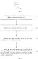
- FIG. 10 is a schematic flowchart of a data interaction method according to an embodiment of the present disclosure.
- the data interaction method is specifically applied to an external terminal, and the external terminal may be configured as a medium for data interaction with an aerosol generating device 10 and a server 20.
- the first identification information of the heat generating assembly in the aerosol generating device is obtained.
- the external terminal may be a PC terminal or a mobile terminal
- the aerosol generating device includes a main body and the heat generating assembly.
- the heat generating assembly has the first identification information.
- the first identification information may specifically be a two-dimensional code and/or a barcode, and the mobile terminal may recognize the two-dimensional code and/or barcode to obtain the first identification information.
- the first identification information is sent to the server.
- the server After the server receives the first identification information, it generates the characteristic parameters accordingly, and the characteristic parameters provided by the server according to the first identification information are obtained.
- the characteristic parameters are sent to the main body in the aerosol generating device, such that the main body can heat the heat generating assembly according to the characteristic parameters, and the main body can further use the heat generating assembly to heat the aerosol generating substrate to generate aerosol.
- the characteristic parameters correspond to a type of the heat generating assembly.
Landscapes
- Engineering & Computer Science (AREA)
- Theoretical Computer Science (AREA)
- General Physics & Mathematics (AREA)
- Databases & Information Systems (AREA)
- Physics & Mathematics (AREA)
- General Engineering & Computer Science (AREA)
- Data Mining & Analysis (AREA)
- Library & Information Science (AREA)
- Computer Networks & Wireless Communication (AREA)
- Human Computer Interaction (AREA)
- Cooling Or The Like Of Electrical Apparatus (AREA)
- Stored Programmes (AREA)
- Control Of Resistance Heating (AREA)
Abstract
Description
- The present disclosure relates to the field of display technologies, and in particular to an aerosol generating device, a heat generating assembly, and a data exchange method.
- An existing heated non-combustible aerosol generating device conventionally applies a heating element to heat an aerosol generating substrate to form a continuous smoking effect for a user to inhale. After the inhalation is completed, the user pulls the aerosol generating substrate out of the heating element to realize the separation of the heating element and the aerosol generating substrate.
- The aerosol generating substrate may produce a certain amount of adhesive attached to the heating element after heating, forming a bonded state, and the adhesive will remain on the surface of the heating element to accumulate further, resulting in a certain degree of increase in the outer diameter of the heating element, which causes the loss of the heating element loss, thereby affecting the taste of fuming products and reducing the life of the heated non-combustible aerosol generating device.
- The present disclosure provides an aerosol generating device, a heat generating assembly, and a data exchange method to solve the problem of the related art in which heating elements cannot be easily replaced.
- To solve the above technical problems, a technical solution adopted by the present disclosure is to provide an aerosol generating device, including: a main body; and a heat generating assembly, detachably connected to the main body; wherein the heat generating assembly includes first identification information, and the first identification information is configured to be identified by a server; the main body is configured to obtain characteristic parameters provided by the server according to the first identification information and to heat the heat generating assembly according to the characteristic parameters, for further heating an aerosol generating substrate with the heat generating assembly to generate aerosol; the characteristic parameters correspond to a type of the heat generating assembly.
- In some embodiments, the main body establishes a data connection with an external terminal, the heat generating assembly is configured to send the first identification information to the server through the external terminal, and the main body is further configured to obtain the characteristic parameters obtained by the server according to the first identification information from the server through the external terminal.
- In some embodiments, the first identification information is a serial number; the characteristic parameters stored in the server are generated according to the first identification information, and the main body is configured to obtain, through the external terminal, the characteristic parameters generated by the server according to the serial number.
- In some embodiments, the first identification information is a barcode; the main body is configured to obtain, through the external terminal, the characteristic parameters generated by the server identifying the barcode.
- In some embodiments, the first identification information is a two-dimensional code; the main body is configured to obtain, through the external terminal, the characteristic parameters generated by the server identifying the two-dimensional code.
- In some embodiments, the first identification information is RFID tag information; the server is configured to obtain the RFID tag information and generate the characteristic parameters through a RFID identifier.
- In some embodiments, the main body includes a communication module, and the main body is configured to perform data interaction with the external terminal through the communication module.
- In some embodiments, the communication module is one or more of a WIFI communication module, a Bluetooth communication module, or a near field communication (NFC) communication module.
- In some embodiments, the communication module is a data interface performing data interaction with the external terminal through a data line.
- In some embodiments, the main body further includes: a housing assembly; and a controller, arranged in the housing assembly; wherein the heat generating assembly is detachably connected to the housing assembly; when connected with the housing assembly, the heat generating assembly is electrically connected with the controller; the controller is configured to obtain, through the communication module, the characteristic parameters from the server.
- In some embodiments, the main body includes a first main body portion and a second main body portion; the first main body portion is configured to accommodate a battery, and the second main body portion is configured to connect with the heat generating assembly.
- In some embodiments, the second main body portion is arranged with a first connector and the heat generating assembly is arranged with a second connector, for connecting the second body portion and the heat generating assembly.
- In some embodiments, the aerosol generating device further includes a first cover detachably connected to the main body; when the heat generating assembly is connected to the main body, the first cover is sleeved on the heat generating assembly.
- In some embodiments, the aerosol generating device further includes a second cover detachably connected to the main body; the second cover is sleeved on the heat generating assembly and the second main body portion; or, the second cover is sleeved on the first cover and the second main body portion.
- In some embodiments, the main body includes second identification information; the second identification information is configured to be identified by the server; the main body is configured to obtain basic parameters generated by the server according to the second identification information, and update and/or upgrade according to the basic parameters.
- In some embodiments, the heat generating assembly further includes: a heat generating body; and a first conductive terminal, connected to the heat generating body; wherein the main body includes a second conductive terminal; when the first conductive terminal and the second conductive terminal are connected, the main body is configured to supply power to the heat generating body; the characteristic parameters include heat generating body parameters and heating parameters in the heat generating assembly; the heat generating body parameters represent a corresponding relationship between a resistance value and a temperature of the heat generating body of the heat generating assembly; the main body is further configured to detect the resistance value of the heat generating body, determine the temperature of the heat generating body according to the heat generating body parameters, and heat the heat generating assembly according to the temperature of the heat generating body and the heating parameters.
- In some embodiments, the main body is configured to control the temperature of the heat generating body by changing a pulse frequency and/or a pulse amplitude and/or a duty cycle of power supplied to the heat generating body.
- To solve the above technical problems, another technical solution adopted by the present disclosure is to provide a heat generating assembly, detachably connected to a main body of an aerosol generating device; wherein the heat generating assembly includes first identification information, and the first identification information is configured to be identified by a server; the main body is configured to obtain characteristic parameters provided by the server according to the first identification information and to heat the heat generating assembly according to the characteristic parameters, for further heating an aerosol generating substrate with the heat generating assembly to generate aerosol; the characteristic parameters correspond to a type of the heat generating assembly.
- In some embodiments, the heat generating assembly further includes: a heat generating body; and a first conductive terminal, connected to the heat generating body; wherein the first conductive terminal is configured to be connected to a second conductive terminal of the main body for the main body supplying power to the heat generating body.
- To solve the above technical problems, another technical solution adopted by the present disclosure is to provide a data interaction method, applied to an external terminal; wherein the external terminal is configured to perform data interaction with an aerosol generating device and a server; the data interaction method includes: obtaining first identification information of a heat generating assembly in the aerosol generating device; sending the first identification information to the server; obtaining characteristic parameters provided by the server according to the first identification information; and sending the characteristic parameters to a main body in the aerosol generating device, such that the main body heats the heat generating assembly according to the characteristic parameters for further heating the aerosol generating substrate with the heat generating assembly to generate aerosol.
- The beneficial effect of the present disclosure is that, in contrast to the related art, the present disclosure provides an aerosol generating device including a main body; and a heat generating assembly detachably connected to the main body. The heat generating assembly includes first identification information, the first identification information may be configured to be identified by a server. The main body is configured to obtain characteristic parameters provided by the server according to the first identification information and to heat the heat generating assembly according to the characteristic parameters for further heating the aerosol generating substrate with the heat generating assembly to generate aerosol. The characteristic parameters correspond to a type of the heat generating assembly. In the above manner, by setting the heat generating assembly in a detachable structure and setting the first identification information on the heat generating assembly, the server can generate corresponding characteristic parameters according to the first identification information. On the one hand, the parts of the aerosol generating device can be replaced at will, reducing the cost of use; and on the other hand, ensuring that when the parts are replaced, they are not replaced with counterfeit parts, which affect the user's use. In addition, the characteristic parameters are protected in the server, reducing the cost of storage media and facilitating the real-time update of the product.
- To illustrate the technical solutions more clearly in the embodiments of the present disclosure, the following will be briefly described in the description of the embodiments required to use the attached drawings. It is obvious that the following description of the attached drawings are only some of the embodiments of the present disclosure, and those skilled in the art, without creative work, can also obtain other attached drawings based on these drawings.
-
FIG. 1 is a structural schematic view of an aerosol generating device according to an embodiment of the present disclosure. -
FIG. 2 is a schematic view of data interaction between an aerosol generating device and a server according to an embodiment of the present disclosure. -
FIG. 3 is a structural schematic view of an aerosol generating device according to another embodiment of the present disclosure. -
FIG. 4 is a schematic view of a temperature-time change curve according to an embodiment of the present disclosure. -
FIG. 5 is a schematic view of a pulse voltage according to an embodiment of the present disclosure. -
FIG. 6 is a structural schematic view of a main body of the aerosol generating device shown inFIG. 1 . -
FIG. 7 is a structural schematic view of an aerosol generating device according to further another embodiment of the present disclosure. -
FIG. 8 is a structural schematic view of a heat generating assembly according to an embodiment of the present disclosure. -
FIG. 9 is a structural schematic view of a server according to an embodiment of the present disclosure. -
FIG. 10 is a schematic flowchart of a data interaction method according to an embodiment of the present disclosure. - The technical solutions in the embodiments of the present disclosure will be clearly and completely described below in conjunction with the drawings in the embodiments of the present disclosure. It can be understood that the specific embodiments described here are only used to explain the present disclosure, but not to limit the present disclosure. In addition, it should be noted that, for ease of description, the drawings only show a part of the structure related to the present disclosure instead of all the structure. Based on the embodiments in the present disclosure, all other embodiments obtained by those skilled in the art without creative work shall fall within the scope of the present disclosure.
- The terms "first", "second", etc. in the present disclosure are intended to distinguish different objects, rather than to describe a specific sequence. In addition, the terms "including" and "having", and any variations thereof are intended to cover non-exclusive inclusions. For example, a process, method, system, product, or device that includes a series of steps or units is not limited to the listed steps or units, but optionally includes unlisted steps or units, or optionally also includes other steps or units inherent to these processes, methods, products, or devices.
- Mentioning "embodiments" herein means that a specific feature, structure, or characteristic described in conjunction with the embodiments may be included in at least one embodiment of the present disclosure. The appearance of the phrase in various places in the specification does not necessarily refer to the same embodiment, nor is it an independent or alternative embodiment mutually exclusive with other embodiments. Those skilled in the art clearly and implicitly understand that the embodiments described herein can be combined with other embodiments.
- Referring to
FIGS. 1-3 ,FIG. 1 is a structural schematic view of an aerosol generating device according to an embodiment of the present disclosure,FIG. 2 is a schematic view of data interaction between an aerosol generating device and a server according to an embodiment of the present disclosure, andFIG. 3 is a structural schematic view of an aerosol generating device according to another embodiment of the present disclosure. The left half ofFIG. 3 shows an overall schematic view of theaerosol generating device 10, and the right half shows a disassembly schematic view thereof. Theaerosol generating device 10 includes amain body 11 and aheat generating assembly 12. Themain body 11 and theheat generating assembly 12 are detachably connected. - Specifically, the
heat generating assembly 12 includes first identification information, and the first identification information may be configured to be identified by aserver 20. Themain body 11 is configured to obtain characteristic parameters provided by theserver 20 according to the first identification information and to heat the heat generating assembly according to the characteristic parameters for further heating the aerosol generating substrate with the heat generating assembly to generate aerosol. The characteristic parameters correspond to a type of the heat generating assembly. - Among them, the characteristic parameters are formed according to different types of
heat generating assemblies 12. Due to the influence of factors such as the material, process, and manufacturing device of a heating body in theheat generating assemblies 12, its characteristic parameters (such as "temperature T-resistance R" curve, initial resistance value R0, temperature coefficient of resistance (TCR), etc.) are different. During product production, theheat generating assembly 12 is placed in a testing device to test the characteristic parameters of theheat generating assembly 12 of different types. - In some embodiments, the
server 20 stores a characteristic parameter-first identification information data packet. After theserver 20 obtains the first identification information, theserver 20 may unlock the characteristic parameter-first identification information data packet through the first identification information to generate corresponding characteristic parameters and provide to themain body 11. - In other embodiments, the
server 20 stores a corresponding algorithm. After the first identification information is input, the characteristic parameters are obtained through the algorithm and provided to themain body 11. - Specifically, the first identification information may be the unique identification information of each
heat generating assembly 12 or the unique identification information of theheat generating assemblies 12 of the same type. Therefore, the characteristic parameters obtained according to the first identification information may correspond to a uniqueheat generating assembly 12. - In other embodiments, the characteristic parameters correspond to heat generating
assembly 12 of a type. Since the characteristic parameters are fixed, only the said characteristic parameters can be applied to heat the adaptedheat generating assembly 12. When the type of the connectedheat generating assembly 12 does not correspond to the type corresponding to the characteristic parameters, theheat generating assembly 12 may not heat the aerosol generating substrate well and the aerosol inhalation taste will become poor. In this way, it is possible to prevent changing the type of theheat generating assembly 12 at will. When the user replaces theheat generating assembly 12, only theheat generating assembly 12 of the same type can be replaced. - In some embodiments, the
main body 11 specifically includes a firstmain body portion 11a and a secondmain body portion 11b. The firstmain body portion 11a is configured to accommodate a battery, and the secondmain body portion 11b is configured to accommodate a controller, etc. and to connect with theheat generating assembly 12. For example, the secondmain body portion 11b is arranged with a first connector, and theheat generating assembly 12 is arranged with a second connector for connecting thesecond body portion 11b and theheat generating assembly 12. In some embodiments, the first and second connector may be a buckle, a screw, or the like. In addition, theheat generating assembly 12 may also be connected to the firstmain body portion 11a through a bottom. - In some embodiments, the
aerosol generating device 10 further includes afirst cover 14 and asecond cover 15 that are detachably connected to themain body 11. When theheat generating assembly 12 is fixedly connected to themain body 11, thefirst cover 14 may be sleeved on theheat generating assembly 12 to protect theheat generating assembly 12; further, thesecond cover 15 may be sleeved on the heat generating assembly 12 (or the first cover 14) and the secondmain body portion 11b for protecting theheat generating assembly 12 and the secondmain body portion 11b. - In some embodiments, the characteristic parameters include heat generating body parameters and heating parameters in the
heat generating assembly 12. The heat generating body parameters represent a corresponding relationship between the resistance value and the temperature of the heat generating body. - Among them, the heat generating body parameters are formed according to different types of
heat generating assemblies 12. Due to the influence of factors such as the material, process, and manufacturing device of a heat generating body in theheat generating assembly 12, its characteristic parameters (such as "temperature T-resistance R" curve, initial resistance value R0, temperature coefficient of resistance (TCR), etc.) are different. During product production, theheat generating assembly 12 is placed in a testing device to test the characteristic parameters of theheat generating assembly 12 of different types. - Among them, the heating parameter may specifically be a "temperature-time variation curve" to determine that the heat generating body is heated to different degrees over time. As shown in
FIG. 4 , -
FIG. 4 is a schematic view of a temperature-time change curve according to an embodiment of the present disclosure. - For example, the controller may control the temperature of the heat generating body according to a preset temperature-time curve with a PID algorithm. The "temperature-time" curve refers to the heating curve for tobacco.
- The following describes embodiments through a specific scenario.
- When a user uses the electronic cigarette to smoke, he/she may connect the
main body 11 and theheat generating assembly 12, and alternatively turn on a switch button arranged on themain body 11. At this time, the electronic cigarette starts to work. - The
main body 11 obtains the characteristic parameters in theserver 20, obtains the corresponding relationship between the resistance value and the temperature of the heat generating body in theheat generating assembly 12, and starts timing. Then themain body 11 obtains the current resistance value of the heat generating body, obtains the current temperature of the heat generating body based on the heat generating body parameters, and controls the voltage of the heat generating body through the "temperature-time" curve. - It can be understood that, to heat the aerosol substrate (such as tobacco) to obtain a better taste, the required heating temperature is different in different time periods. In some embodiments, as shown in
FIG. 3 , the abscissa represents time, and the ordinate represents temperature. - In the T0-T1 time period, the heat generating body is heated to increase its temperature from normal temperature W0 to temperature W1.
- In the T1-T2 time period, the temperature of the heat generating body is kept at W1.
- In the T2-T3 time period, the temperature of the heat generating body is decreased from W1 to temperature W2.
- In the T3-T4 time period, the temperature of the heat generating body is kept at W2.
- After T4, the temperature of the heat generating body is decreased from W2 to normal temperature.
- Among them, in a specific embodiment, the value of T1 may be 5-10s, the value of T2 may be 12-18s, the value of W1 may be 320-360°C, and the value of W2 may be 300-340°C.
- In an embodiment, T1=7s, T2=15s, W1=340°C, W2=320°C. Suppose that when the temperature of the heat generating body drops by 1°C, its resistance decreases by 2.28mQ, then when the temperature drops from W1 to W2, that is, when the temperature drops by 20°C, its resistance is required to be lowered by 20∗2.28mΩ.
- Further, when using electric energy to control the heating temperature of the heat generating body, methods may include changing the pulse frequency and/or pulse amplitude and/or duty cycle of the power supplied to the heat generating body to provide temperature control of the heat generating body, such that the aerosol device may be controlled to release smoke with a better taste. As shown in
FIG. 5, FIG. 5 is a schematic view of a pulse voltage according to an embodiment of the present disclosure. For example, when an enable switch is turned on in the t1 time period, and the battery provides electric energy to the heat generating body; the enable switch is closed in the t2 time period, and the battery does not provide electric energy to the heat generating body. Therefore, the temperature of the heat generating body can be adjusted by adjusting the percentage of tl in the period T. Specifically, increasing the duty ratio of tl, the temperature of the heat generating body increases, and decreasing the duty ratio of tl, the temperature of the heat generating body decreases. - In practical applications, the
main body 11 and theheat generating assembly 12 may be sold as a whole, and one or two of themain body 11 and theheat generating assembly 12 may be sold in combination, which can facilitate the user to replace any of the components. For example, the user may purchase themain body 11 and theheat generating assembly 12 at the same time when purchasing for the first time. During use, when theheat generating assembly 12 is worn out and required to be replaced, only theheat generating assembly 12 of the same type as the previous one is required to be purchased. - It is to be noted that when the new
heat generating assembly 12 purchased by the user has a different type compared with the worn out one, themain body 11 can still obtain the characteristic parameters corresponding to theheat generating assembly 12 from theserver 20 according to the first identification information of theheat generating assembly 12 and heat theheat generating body 12 according to the corresponding characteristic parameters. In this way, even if one of the components is replaced, the heating effect and taste will not be affected. - Through the above method, the user may mix and match at will, rather than buying in a bundle with a poor experience, thus stimulating his/her desire to purchase.
- Different from the related art, the aerosol generating device provided in the embodiments includes: a main body; and a heat generating assembly detachably connected to the main body. The heat generating assembly includes first identification information, the first identification information may be configured to be identified by a server. The main body is configured to obtain characteristic parameters provided by the server according to the first identification information and to heat the heat generating assembly according to the characteristic parameters for further heating the aerosol generating substrate with the heat generating assembly to generate aerosol. The characteristic parameters correspond to a type of the heat generating assembly. In the above manner, by setting the heat generating assembly in a detachable structure and setting the first identification information on the heat generating assembly, the server can generate corresponding characteristic parameters according to the first identification information. On the one hand, the parts of the aerosol generating device can be replaced at will, reducing the cost of use; and on the other hand, ensuring that when the parts are replaced, they are not replaced with counterfeit parts, which affect the user's use. In addition, the characteristic parameters are protected in the server, reducing the cost of storage media and facilitating the real-time update of the product.
- Referring to
FIG. 6 , themain body 11 includes acontroller 111 and acommunication module 112, and themain body 11 can perform data interaction with theserver 20 through thecommunication module 112 to obtain the characteristic parameters. - In a specific embodiment, the
main body 11 establishes a data connection with an external terminal, theheat generating assembly 12 sends the first identification information to theserver 20 through the external terminal, and themain body 11 further obtains the characteristic parameters obtained by theserver 20 according to the first identification information from theserver 20 through the external terminal. - Specifically, the external terminal may be a PC terminal, such as a computer, etc., or a mobile terminal, such as a mobile phone, a tablet computer, etc.
- In a specific embodiment, the
main body 11 may establish a data connection with the external terminal through thecommunication module 112. - In some embodiments, the
communication module 112 may be any one or more of a WIFI communication module, a Bluetooth communication module, or a near field communication (NFC) communication module. Thecommunication module 112 may also be a data interface, etc., and perform data interaction with the external terminal through a data line. Themain body 11 performs data interaction with the external terminal through thecommunication module 112 to obtain the characteristic parameters. Thecontroller 111 heats theheat generating assembly 12 according to the characteristic parameters obtained by thecommunication module 112. - In a specific embodiment, the first identification information is a serial number. In the replacement process, the
server 20 can obtain the serial number and generate related characteristic parameters through the external terminal such as a PC or a mobile terminal as a medium. - In a specific embodiment, the first identification information is a two-dimensional code or/and a barcode. In the replacement process, the
server 20 can scan the two-dimensional code or/and barcode through the external terminal such as a mobile terminal as a medium and generate the related characteristic parameters according to the two-dimensional code or/and barcode. Among them, the characteristic parameters stored by theserver 20 are generated according to the first identification information. - In a specific embodiment, the
communication module 112 is not limited to wireless communication such as a WIFI communication module, a Bluetooth communication module, or NFC, and may also directly perform wired communication through a data line, which is not limited here. - In a specific embodiment, the first identification information may also be RFID tag information with higher security. In the replacement process, the
server 20 may obtain the RFID tag information through a RFID identifier as a medium and generate related characteristic parameters. The security of RFID tag information is better, and it is not easy to be plagiarized, replaced, and modified. - In a specific embodiment, the
main body 11 may further include second identification information. The second identification information is similar to the first identification information, and may be one or more of a serial number, a two-dimensional code, a barcode, and RFID tag information. The second identification information may also be configured to be identified by theserver 20, and the main body is configured to obtain basic parameters generated by theserver 20 according to the second identification information, and update and/or upgrade according to the basic parameters. - Specifically, the
main body 11 may directly obtain relevant basic parameters from theserver 20 directly through its own second identification information, so as to perform a soft update and/or upgrade of itself. - Further, the
main body 11 specifically includes a housing assembly and a controller arranged in the housing assembly. Theheat generating assembly 12 is detachably connected to the housing assembly. When connected with the housing assembly, theheat generating assembly 12 is electrically connected with the controller. The controller is configured to obtain the characteristic parameters from theserver 20 and heat theheat generating assembly 12 according to the characteristic parameters, so as to further use theheat generating assembly 12 to heat the aerosol generating substrate to generate aerosol. The controller is configured to obtain the characteristic parameters from theserver 20 with thecommunication module 112. - Referring to
FIG. 7, FIG. 7 is a structural schematic view of an aerosol generating device according to further another embodiment of the present disclosure. Theaerosol generating device 10 includes amain body 11 and aheat generating assembly 12. Themain body 11 and theheat generating assembly 12 are detachably connected. - In some embodiments, the
heat generating assembly 12 includes a firstconductive terminal 121, and themain body 11 includes acontroller 111 and a secondconductive terminal 113 connected to thecontroller 111. When the firstconductive terminal 121 and the secondconductive terminal 113 are connected, themain body 11 can supply power to theheat generating assembly 12. Theheat generating assembly 12 specifically includes a heating body, and themain body 11 is specifically configured to supply power to the heat generating body. - Referring to
FIG. 8, FIG. 8 is a structural schematic view of a heat generating assembly according to an embodiment of the present disclosure. Theheat generating assembly 12 includes a firstconductive terminal 121 and aheat generating body 122. Theheat generating assembly 12 is configured to detachably connect to the main body of the aerosol generating device. When connected to themain body 11, the firstconductive terminal 121 is electrically connected to the secondconductive terminal 113 of themain body 11. - The
heat generating assembly 12 includes first identification information, and the first identification information may be configured to be identified by aserver 20. Themain body 11 is configured to obtain characteristic parameters provided by theserver 20 according to the first identification information and to heat theheat generating assembly 12 according to the characteristic parameters for further heating the aerosol generating substrate with theheat generating assembly 12 to generate aerosol. - Referring to
FIG. 9 , the present disclosure further provides aserver 20, which is configured for data exchange with theaerosol generating device 10 described in any of the above embodiments. - Specifically, the
server 20 is configured to identify the first identification information of theheat generating assembly 12 to provide characteristic parameters, which may be originally stored in the server, although the first identification information is provided after being verified and unlocked. The characteristic parameters may also be generated by calculating the first identification information by a corresponding algorithm, which is not limited herein. Theserver 20 sends the characteristic parameters to themain body 11, such that themain body 11 heats theheat generating assembly 12 according to the characteristic parameters. In this way, themain body 11 further uses theheat generating body 12 to heat the aerosol generating substrate to generate aerosol, and the characteristic parameters correspond to a type of theheat generating body 12. - It can be understood that the foregoing heat generating assembly and server embodiments are similar to the structure and working principle of the heat generating assembly and server in the foregoing embodiment of the aerosol generating device, and will not be repeated here.
- Referring to
FIG. 10, FIG. 10 is a schematic flowchart of a data interaction method according to an embodiment of the present disclosure. The data interaction method is specifically applied to an external terminal, and the external terminal may be configured as a medium for data interaction with anaerosol generating device 10 and aserver 20. - At block S11: obtaining first identification information of a heat generating assembly in the aerosol generating device.
- The first identification information of the heat generating assembly in the aerosol generating device is obtained.
- Specifically, the external terminal may be a PC terminal or a mobile terminal, and the aerosol generating device includes a main body and the heat generating assembly. The heat generating assembly has the first identification information.
- In a specific embodiment, the first identification information may specifically be a two-dimensional code and/or a barcode, and the mobile terminal may recognize the two-dimensional code and/or barcode to obtain the first identification information.
- At block S 12: sending the first identification information to the server.
- The first identification information is sent to the server.
- At block S13: obtaining characteristic parameters provided by the server according to the first identification information.
- After the server receives the first identification information, it generates the characteristic parameters accordingly, and the characteristic parameters provided by the server according to the first identification information are obtained.
- At block S14: sending the characteristic parameters to a main body in the aerosol generating device, such that the main body heats the heat generating assembly according to the characteristic parameters for further heating the aerosol generating substrate with the heat generating assembly to generate aerosol.
- After obtaining the characteristic parameters provided by the server, the characteristic parameters are sent to the main body in the aerosol generating device, such that the main body can heat the heat generating assembly according to the characteristic parameters, and the main body can further use the heat generating assembly to heat the aerosol generating substrate to generate aerosol. The characteristic parameters correspond to a type of the heat generating assembly.
- The specific embodiment of the foregoing data exchange method is similar to the foregoing embodiments of the aerosol generating device, and will not be repeated herein.
- The above are only implementations of the present disclosure, and do not limit the scope of the present disclosure. Any equivalent structure or equivalent process transformation made according to the specification of this application and the accompanying drawings, or applied directly or indirectly in other related technical fields, are equally included in the scope of the present disclosure.
Claims (20)
- An aerosol generating device, characterized by comprising:a main body; anda heat generating assembly, detachably connected to the main body;wherein the heat generating assembly comprises first identification information, and the first identification information is configured to be identified by a server; the main body is configured to obtain characteristic parameters provided by the server according to the first identification information and to heat the heat generating assembly according to the characteristic parameters, for further heating an aerosol generating substrate with the heat generating assembly to generate aerosol; the characteristic parameters correspond to a type of the heat generating assembly.
- The aerosol generating device according to claim 1, wherein the main body establishes a data connection with an external terminal, the heat generating assembly is configured to send the first identification information to the server through the external terminal, and the main body is further configured to obtain the characteristic parameters obtained by the server according to the first identification information from the server through the external terminal.
- The aerosol generating device according to claim 2, wherein the first identification information is a serial number; the characteristic parameters stored in the server are generated according to the first identification information, and the main body is configured to obtain, through the external terminal, the characteristic parameters generated by the server according to the serial number.
- The aerosol generating device according to claim 2, wherein the first identification information is a barcode; the main body is configured to obtain, through the external terminal, the characteristic parameters generated by the server identifying the barcode.
- The aerosol generating device according to claim 2, wherein the first identification information is a two-dimensional code; the main body is configured to obtain, through the external terminal, the characteristic parameters generated by the server identifying the two-dimensional code.
- The aerosol generating device according to claim 2, wherein the first identification information is RFID tag information; the server is configured to obtain the RFID tag information and generate the characteristic parameters through a RFID identifier.
- The aerosol generating device according to claim 2, wherein the main body comprises a communication module, and the main body is configured to perform data interaction with the external terminal through the communication module.
- The aerosol generating device according to claim 7, wherein the communication module is one or more of a WIFI communication module, a Bluetooth communication module, or a near field communication (NFC) communication module.
- The aerosol generating device according to claim 7, wherein the communication module is a data interface performing data interaction with the external terminal through a data line.
- The aerosol generating device according to claim 7, wherein the main body further comprises:a housing assembly; anda controller, arranged in the housing assembly;wherein the heat generating assembly is detachably connected to the housing assembly; when connected with the housing assembly, the heat generating assembly is electrically connected with the controller; the controller is configured to obtain, through the communication module, the characteristic parameters from the server.
- The aerosol generating device according to claim 1, wherein the main body comprises a first main body portion and a second main body portion; the first main body portion is configured to accommodate a battery, and the second main body portion is configured to connect with the heat generating assembly.
- The aerosol generating device according to claim 11, wherein the second main body portion is arranged with a first connector and the heat generating assembly is arranged with a second connector, for connecting the second body portion and the heat generating assembly.
- The aerosol generating device according to claim 12, further comprising a first cover detachably connected to the main body; when the heat generating assembly is connected to the main body, the first cover is sleeved on the heat generating assembly.
- The aerosol generating device according to claim 13, further comprising a second cover detachably connected to the main body; the second cover is sleeved on the heat generating assembly and the second main body portion; or, the second cover is sleeved on the first cover and the second main body portion.
- The aerosol generating device according to claim 1, wherein the main body comprises second identification information; the second identification information is configured to be identified by the server; the main body is configured to obtain basic parameters generated by the server according to the second identification information, and update and/or upgrade according to the basic parameters.
- The aerosol generating device according to claim 1, wherein the heat generating assembly further comprises:a heat generating body; anda first conductive terminal, connected to the heat generating body;wherein the main body comprises a second conductive terminal; when the first conductive terminal and the second conductive terminal are connected, the main body is configured to supply power to the heat generating body;the characteristic parameters comprise heat generating body parameters and heating parameters in the heat generating assembly; the heat generating body parameters represent a corresponding relationship between a resistance value and a temperature of the heat generating body of the heat generating assembly;the main body is further configured to detect the resistance value of the heat generating body, determine the temperature of the heat generating body according to the heat generating body parameters, and heat the heat generating assembly according to the temperature of the heat generating body and the heating parameters.
- The aerosol generating device according to claim 16, wherein the main body is configured to control the temperature of the heat generating body by changing a pulse frequency and/or a pulse amplitude and/or a duty cycle of power supplied to the heat generating body.
- A heat generating assembly, characterized by detachably connected to a main body of an aerosol generating device;
wherein the heat generating assembly comprises first identification information, and the first identification information is configured to be identified by a server; the main body is configured to obtain characteristic parameters provided by the server according to the first identification information and to heat the heat generating assembly according to the characteristic parameters, for further heating an aerosol generating substrate with the heat generating assembly to generate aerosol; the characteristic parameters correspond to a type of the heat generating assembly. - The heat generating assembly according to claim 18, further comprising:a heat generating body; anda first conductive terminal, connected to the heat generating body;wherein the first conductive terminal is configured to be connected to a second conductive terminal of the main body for the main body supplying power to the heat generating body.
- A data interaction method, applied to an external terminal; characterized in that the external terminal is configured to perform data interaction with an aerosol generating device and a server;
the data interaction method comprises:obtaining first identification information of a heat generating assembly in the aerosol generating device;sending the first identification information to the server;obtaining characteristic parameters provided by the server according to the first identification information; andsending the characteristic parameters to a main body in the aerosol generating device, such that the main body heats the heat generating assembly according to the characteristic parameters for further heating the aerosol generating substrate with the heat generating assembly to generate aerosol.
Applications Claiming Priority (2)
| Application Number | Priority Date | Filing Date | Title |
|---|---|---|---|
| CN201910838951.9A CN110623305A (en) | 2019-09-05 | 2019-09-05 | An aerosol generating device, a heating component and a data interaction method |
| PCT/CN2020/111116 WO2021043028A1 (en) | 2019-09-05 | 2020-08-25 | Aerosol generating device, heating assembly and data exchange method |
Publications (3)
| Publication Number | Publication Date |
|---|---|
| EP4026445A1 true EP4026445A1 (en) | 2022-07-13 |
| EP4026445A4 EP4026445A4 (en) | 2022-11-02 |
| EP4026445B1 EP4026445B1 (en) | 2025-07-09 |
Family
ID=68971222
Family Applications (1)
| Application Number | Title | Priority Date | Filing Date |
|---|---|---|---|
| EP20861068.3A Active EP4026445B1 (en) | 2019-09-05 | 2020-08-25 | Aerosol generating device and data exchange method |
Country Status (5)
| Country | Link |
|---|---|
| EP (1) | EP4026445B1 (en) |
| JP (1) | JP7333469B2 (en) |
| KR (1) | KR102741094B1 (en) |
| CN (1) | CN110623305A (en) |
| WO (1) | WO2021043028A1 (en) |
Cited By (1)
| Publication number | Priority date | Publication date | Assignee | Title |
|---|---|---|---|---|
| WO2025224428A1 (en) * | 2024-04-23 | 2025-10-30 | Nicoventures Trading Limited | Heating method for aerosol provision system and aerosol provision system and aerosol heating control system |
Families Citing this family (4)
| Publication number | Priority date | Publication date | Assignee | Title |
|---|---|---|---|---|
| CN110584207B (en) * | 2019-09-03 | 2025-02-21 | 深圳麦克韦尔科技有限公司 | An aerosol generating device, a heating component and a storage component |
| CN110623305A (en) * | 2019-09-05 | 2019-12-31 | 深圳麦克韦尔科技有限公司 | An aerosol generating device, a heating component and a data interaction method |
| CN112790440A (en) * | 2020-12-25 | 2021-05-14 | 深圳市基克纳科技有限公司 | A kind of atomizer heating element replacement method, device and atomizer |
| CN112806612A (en) * | 2021-01-11 | 2021-05-18 | 东莞市麦斯莫科电子科技有限公司 | Power supply host and electron cigarette of applicable multiple heater |
Family Cites Families (21)
| Publication number | Priority date | Publication date | Assignee | Title |
|---|---|---|---|---|
| EP2110034A1 (en) | 2008-04-17 | 2009-10-21 | Philip Morris Products S.A. | An electrically heated smoking system |
| US20140338685A1 (en) * | 2013-05-20 | 2014-11-20 | Sis Resources, Ltd. | Burning prediction and communications for an electronic cigarette |
| CN116172269A (en) * | 2014-08-13 | 2023-05-30 | 菲利普莫里斯生产公司 | Aerosol generating system including a multipurpose computing device |
| CN106211203A (en) * | 2015-04-29 | 2016-12-07 | 中兴通讯股份有限公司 | Lock network data updating method and device |
| CN104933382B (en) * | 2015-07-02 | 2018-01-09 | 卓尔悦欧洲控股有限公司 | Power supply device, aerosol generating device and identification control method thereof |
| CN106708544A (en) * | 2015-08-13 | 2017-05-24 | 中兴通讯股份有限公司 | Method and apparatus for assisting in firmware upgrading of electronic devices, and terminal |
| CN105717812B (en) * | 2016-01-25 | 2019-03-29 | 深圳市合元科技有限公司 | An intelligent control method, control system and electronic cigarette based on electronic cigarette |
| US20170266397A1 (en) * | 2016-03-21 | 2017-09-21 | Advanced Grow Labs, Llc | Vaporizing device system and method |
| CA3022310C (en) | 2016-04-27 | 2021-07-27 | Japan Tobacco Inc. | Flavor inhaler cartridge and flavor inhaler |
| CN109561732B (en) * | 2016-07-27 | 2021-06-29 | 日本烟草产业株式会社 | Fragrance inhalers, cartridges and fragrance units |
| KR20180124739A (en) * | 2017-05-11 | 2018-11-21 | 주식회사 케이티앤지 | An aerosol generating device for controlling the temperature of a heater according to the type of cigarette and method thereof |
| KR102116961B1 (en) | 2017-07-21 | 2020-06-02 | 주식회사 아모센스 | heater assembly for cylinderical type electronic cigarette and cylinderical type electronic cigarette including the same |
| CN112006339B (en) * | 2018-02-09 | 2023-07-07 | 常州市派腾电子技术服务有限公司 | Device and method for identifying heating wire, electronic cigarette and computer storage medium |
| GB201803033D0 (en) * | 2018-02-26 | 2018-04-11 | Nerudia Ltd | Systems for managing smoking substitute devices and associated methods |
| GB201805168D0 (en) * | 2018-03-29 | 2018-05-16 | Nicoventures Holdings Ltd | A control device for an electronic aerosol provision system |
| CN109330027B (en) * | 2018-08-24 | 2022-10-21 | 深圳麦克韦尔科技有限公司 | Electronic smoking set, control method thereof, heating component, electronic equipment and storage medium |
| CN109222246A (en) * | 2018-09-30 | 2019-01-18 | 湖北中烟工业有限责任公司 | A kind of intelligent interactive electric heating aerosol generates system and its operating method |
| CN109512034B (en) * | 2018-12-10 | 2022-06-21 | 深圳麦克韦尔科技有限公司 | Smoking set and method of installing same |
| CN109712015A (en) * | 2018-12-21 | 2019-05-03 | 东莞市麦斯莫科电子科技有限公司 | Intelligent electronic cigarette social intercourse system and method |
| CN211861817U (en) * | 2019-09-05 | 2020-11-06 | 深圳麦克韦尔科技有限公司 | An aerosol generating device and a heating component using the same |
| CN110623305A (en) * | 2019-09-05 | 2019-12-31 | 深圳麦克韦尔科技有限公司 | An aerosol generating device, a heating component and a data interaction method |
-
2019
- 2019-09-05 CN CN201910838951.9A patent/CN110623305A/en active Pending
-
2020
- 2020-08-25 WO PCT/CN2020/111116 patent/WO2021043028A1/en not_active Ceased
- 2020-08-25 KR KR1020227011069A patent/KR102741094B1/en active Active
- 2020-08-25 EP EP20861068.3A patent/EP4026445B1/en active Active
- 2020-08-25 JP JP2022514839A patent/JP7333469B2/en active Active
Cited By (1)
| Publication number | Priority date | Publication date | Assignee | Title |
|---|---|---|---|---|
| WO2025224428A1 (en) * | 2024-04-23 | 2025-10-30 | Nicoventures Trading Limited | Heating method for aerosol provision system and aerosol provision system and aerosol heating control system |
Also Published As
| Publication number | Publication date |
|---|---|
| WO2021043028A1 (en) | 2021-03-11 |
| CN110623305A (en) | 2019-12-31 |
| KR20220056231A (en) | 2022-05-04 |
| JP7333469B2 (en) | 2023-08-24 |
| EP4026445B1 (en) | 2025-07-09 |
| JP2022547109A (en) | 2022-11-10 |
| EP4026445A4 (en) | 2022-11-02 |
| KR102741094B1 (en) | 2024-12-11 |
Similar Documents
| Publication | Publication Date | Title |
|---|---|---|
| EP4026445B1 (en) | Aerosol generating device and data exchange method | |
| KR102728486B1 (en) | Aerosol generating device, heating assembly and storage assembly | |
| JP6879497B2 (en) | Electronic cigarette appliances and their control methods, heat generation modules, electronic devices and storage media | |
| EP3666094B1 (en) | Electronic cigarette control method and device | |
| SA521430491B1 (en) | System for age verification | |
| CN109757784B (en) | Electronic cigarette using method and registration authentication method | |
| CN105717812A (en) | Electronic cigarette based intelligent control method and system and electronic cigarette | |
| JP2019522985A (en) | Device for heating smoking material | |
| JP2014511142A (en) | System for communicating with an implantable medical device using a bridge device | |
| US20250194673A1 (en) | Aerosol generating device with modular components | |
| CN112545061A (en) | Temperature control method, electronic cigarette and atomization heating device | |
| CN211861817U (en) | An aerosol generating device and a heating component using the same | |
| KR20230066625A (en) | Modules for aerosol delivery devices | |
| CN211861800U (en) | Aerial fog generating device, heating component and storage component | |
| CN119072249A (en) | Aerosol supply system | |
| CN118829367A (en) | Aerosol supply device | |
| EP4171298B1 (en) | An aerosol-generating device and system comprising a dynamic near-field communication module | |
| CN120322167A (en) | Aerosol generating device with modular heater unit | |
| KR20230066624A (en) | User Profile Module for Aerosol Delivery Devices | |
| WO2025062020A1 (en) | Aerosol provision device | |
| TW202439996A (en) | Aerosol provision device | |
| JP2026510067A (en) | Aerosol generating device and method for certifying a removable battery in an aerosol generating device | |
| KR101645453B1 (en) | Function interruption system for rental electric device | |
| KR20210023458A (en) | Managing system for heat transcription device |
Legal Events
| Date | Code | Title | Description |
|---|---|---|---|
| STAA | Information on the status of an ep patent application or granted ep patent |
Free format text: STATUS: THE INTERNATIONAL PUBLICATION HAS BEEN MADE |
|
| PUAI | Public reference made under article 153(3) epc to a published international application that has entered the european phase |
Free format text: ORIGINAL CODE: 0009012 |
|
| STAA | Information on the status of an ep patent application or granted ep patent |
Free format text: STATUS: REQUEST FOR EXAMINATION WAS MADE |
|
| 17P | Request for examination filed |
Effective date: 20220403 |
|
| AK | Designated contracting states |
Kind code of ref document: A1 Designated state(s): AL AT BE BG CH CY CZ DE DK EE ES FI FR GB GR HR HU IE IS IT LI LT LU LV MC MK MT NL NO PL PT RO RS SE SI SK SM TR |
|
| REG | Reference to a national code |
Ref legal event code: R079 Ipc: A24F0040650000 Ref country code: DE Ref legal event code: R079 Ref document number: 602020054350 Country of ref document: DE Free format text: PREVIOUS MAIN CLASS: A24F0047000000 Ipc: A24F0040650000 |
|
| A4 | Supplementary search report drawn up and despatched |
Effective date: 20221004 |
|
| RIC1 | Information provided on ipc code assigned before grant |
Ipc: A24F 40/53 20200101ALI20220927BHEP Ipc: A24F 40/10 20200101ALI20220927BHEP Ipc: A24F 40/57 20200101ALI20220927BHEP Ipc: A24F 40/65 20200101AFI20220927BHEP |
|
| DAV | Request for validation of the european patent (deleted) | ||
| DAX | Request for extension of the european patent (deleted) | ||
| RAP3 | Party data changed (applicant data changed or rights of an application transferred) |
Owner name: SHENZHEN SMOORE TECHNOLOGY LIMITED |
|
| REG | Reference to a national code |
Free format text: PREVIOUS MAIN CLASS: A24F0040650000 Ipc: A24F0040530000 Ref country code: DE Ref legal event code: R079 Ref document number: 602020054350 Country of ref document: DE |
|
| GRAP | Despatch of communication of intention to grant a patent |
Free format text: ORIGINAL CODE: EPIDOSNIGR1 |
|
| STAA | Information on the status of an ep patent application or granted ep patent |
Free format text: STATUS: GRANT OF PATENT IS INTENDED |
|
| RIC1 | Information provided on ipc code assigned before grant |
Ipc: A24F 40/20 20200101ALN20250225BHEP Ipc: A24F 40/57 20200101ALI20250225BHEP Ipc: A24F 40/53 20200101AFI20250225BHEP |
|
| INTG | Intention to grant announced |
Effective date: 20250313 |
|
| RAP3 | Party data changed (applicant data changed or rights of an application transferred) |
Owner name: SHENZHEN SMOORE TECHNOLOGY LIMITED |
|
| GRAS | Grant fee paid |
Free format text: ORIGINAL CODE: EPIDOSNIGR3 |
|
| GRAA | (expected) grant |
Free format text: ORIGINAL CODE: 0009210 |
|
| STAA | Information on the status of an ep patent application or granted ep patent |
Free format text: STATUS: THE PATENT HAS BEEN GRANTED |
|
| P01 | Opt-out of the competence of the unified patent court (upc) registered |
Free format text: CASE NUMBER: APP_24529/2025 Effective date: 20250522 |
|
| AK | Designated contracting states |
Kind code of ref document: B1 Designated state(s): AL AT BE BG CH CY CZ DE DK EE ES FI FR GB GR HR HU IE IS IT LI LT LU LV MC MK MT NL NO PL PT RO RS SE SI SK SM TR |
|
| REG | Reference to a national code |
Ref country code: GB Ref legal event code: FG4D |
|
| REG | Reference to a national code |
Ref country code: CH Ref legal event code: EP |
|
| REG | Reference to a national code |
Ref country code: IE Ref legal event code: FG4D |
|
| REG | Reference to a national code |
Ref country code: DE Ref legal event code: R096 Ref document number: 602020054350 Country of ref document: DE |
|
| GRAT | Correction requested after decision to grant or after decision to maintain patent in amended form |
Free format text: ORIGINAL CODE: EPIDOSNCDEC |
|
| REG | Reference to a national code |
Ref country code: CH Ref legal event code: PK Free format text: TITEL |
|
| PGFP | Annual fee paid to national office [announced via postgrant information from national office to epo] |
Ref country code: DE Payment date: 20250916 Year of fee payment: 6 |
|
| PGFP | Annual fee paid to national office [announced via postgrant information from national office to epo] |
Ref country code: GB Payment date: 20250919 Year of fee payment: 6 |
|
| REG | Reference to a national code |
Ref country code: NL Ref legal event code: MP Effective date: 20250709 |
|
| PG25 | Lapsed in a contracting state [announced via postgrant information from national office to epo] |
Ref country code: PT Free format text: LAPSE BECAUSE OF FAILURE TO SUBMIT A TRANSLATION OF THE DESCRIPTION OR TO PAY THE FEE WITHIN THE PRESCRIBED TIME-LIMIT Effective date: 20251110 |
|
| PG25 | Lapsed in a contracting state [announced via postgrant information from national office to epo] |
Ref country code: NL Free format text: LAPSE BECAUSE OF FAILURE TO SUBMIT A TRANSLATION OF THE DESCRIPTION OR TO PAY THE FEE WITHIN THE PRESCRIBED TIME-LIMIT Effective date: 20250709 |
|
| REG | Reference to a national code |
Ref country code: AT Ref legal event code: MK05 Ref document number: 1810951 Country of ref document: AT Kind code of ref document: T Effective date: 20250709 |
|
| PG25 | Lapsed in a contracting state [announced via postgrant information from national office to epo] |
Ref country code: IS Free format text: LAPSE BECAUSE OF FAILURE TO SUBMIT A TRANSLATION OF THE DESCRIPTION OR TO PAY THE FEE WITHIN THE PRESCRIBED TIME-LIMIT Effective date: 20251109 |
|
| PG25 | Lapsed in a contracting state [announced via postgrant information from national office to epo] |
Ref country code: NO Free format text: LAPSE BECAUSE OF FAILURE TO SUBMIT A TRANSLATION OF THE DESCRIPTION OR TO PAY THE FEE WITHIN THE PRESCRIBED TIME-LIMIT Effective date: 20251009 |
|
| REG | Reference to a national code |
Ref country code: LT Ref legal event code: MG9D |
|
| PG25 | Lapsed in a contracting state [announced via postgrant information from national office to epo] |
Ref country code: AT Free format text: LAPSE BECAUSE OF FAILURE TO SUBMIT A TRANSLATION OF THE DESCRIPTION OR TO PAY THE FEE WITHIN THE PRESCRIBED TIME-LIMIT Effective date: 20250709 |
|
| PG25 | Lapsed in a contracting state [announced via postgrant information from national office to epo] |
Ref country code: FI Free format text: LAPSE BECAUSE OF FAILURE TO SUBMIT A TRANSLATION OF THE DESCRIPTION OR TO PAY THE FEE WITHIN THE PRESCRIBED TIME-LIMIT Effective date: 20250709 |
|
| PG25 | Lapsed in a contracting state [announced via postgrant information from national office to epo] |
Ref country code: HR Free format text: LAPSE BECAUSE OF FAILURE TO SUBMIT A TRANSLATION OF THE DESCRIPTION OR TO PAY THE FEE WITHIN THE PRESCRIBED TIME-LIMIT Effective date: 20250709 |
|
| PG25 | Lapsed in a contracting state [announced via postgrant information from national office to epo] |
Ref country code: GR Free format text: LAPSE BECAUSE OF FAILURE TO SUBMIT A TRANSLATION OF THE DESCRIPTION OR TO PAY THE FEE WITHIN THE PRESCRIBED TIME-LIMIT Effective date: 20251010 |
|
| PG25 | Lapsed in a contracting state [announced via postgrant information from national office to epo] |
Ref country code: SE Free format text: LAPSE BECAUSE OF FAILURE TO SUBMIT A TRANSLATION OF THE DESCRIPTION OR TO PAY THE FEE WITHIN THE PRESCRIBED TIME-LIMIT Effective date: 20250709 |
|
| PG25 | Lapsed in a contracting state [announced via postgrant information from national office to epo] |
Ref country code: LV Free format text: LAPSE BECAUSE OF FAILURE TO SUBMIT A TRANSLATION OF THE DESCRIPTION OR TO PAY THE FEE WITHIN THE PRESCRIBED TIME-LIMIT Effective date: 20250709 |
|
| PG25 | Lapsed in a contracting state [announced via postgrant information from national office to epo] |
Ref country code: BG Free format text: LAPSE BECAUSE OF FAILURE TO SUBMIT A TRANSLATION OF THE DESCRIPTION OR TO PAY THE FEE WITHIN THE PRESCRIBED TIME-LIMIT Effective date: 20250709 Ref country code: PL Free format text: LAPSE BECAUSE OF FAILURE TO SUBMIT A TRANSLATION OF THE DESCRIPTION OR TO PAY THE FEE WITHIN THE PRESCRIBED TIME-LIMIT Effective date: 20250709 |
|
| PG25 | Lapsed in a contracting state [announced via postgrant information from national office to epo] |
Ref country code: RS Free format text: LAPSE BECAUSE OF FAILURE TO SUBMIT A TRANSLATION OF THE DESCRIPTION OR TO PAY THE FEE WITHIN THE PRESCRIBED TIME-LIMIT Effective date: 20251009 |
|
| PG25 | Lapsed in a contracting state [announced via postgrant information from national office to epo] |
Ref country code: ES Free format text: LAPSE BECAUSE OF FAILURE TO SUBMIT A TRANSLATION OF THE DESCRIPTION OR TO PAY THE FEE WITHIN THE PRESCRIBED TIME-LIMIT Effective date: 20250709 |
|
| PG25 | Lapsed in a contracting state [announced via postgrant information from national office to epo] |
Ref country code: RO Free format text: LAPSE BECAUSE OF FAILURE TO SUBMIT A TRANSLATION OF THE DESCRIPTION OR TO PAY THE FEE WITHIN THE PRESCRIBED TIME-LIMIT Effective date: 20250709 |
|
| REG | Reference to a national code |
Ref country code: CH Ref legal event code: H13 Free format text: ST27 STATUS EVENT CODE: U-0-0-H10-H13 (AS PROVIDED BY THE NATIONAL OFFICE) Effective date: 20260324 |
|
| PG25 | Lapsed in a contracting state [announced via postgrant information from national office to epo] |
Ref country code: SM Free format text: LAPSE BECAUSE OF FAILURE TO SUBMIT A TRANSLATION OF THE DESCRIPTION OR TO PAY THE FEE WITHIN THE PRESCRIBED TIME-LIMIT Effective date: 20250709 |
|
| PG25 | Lapsed in a contracting state [announced via postgrant information from national office to epo] |
Ref country code: DK Free format text: LAPSE BECAUSE OF FAILURE TO SUBMIT A TRANSLATION OF THE DESCRIPTION OR TO PAY THE FEE WITHIN THE PRESCRIBED TIME-LIMIT Effective date: 20250709 |
|
| PG25 | Lapsed in a contracting state [announced via postgrant information from national office to epo] |
Ref country code: IT Free format text: LAPSE BECAUSE OF FAILURE TO SUBMIT A TRANSLATION OF THE DESCRIPTION OR TO PAY THE FEE WITHIN THE PRESCRIBED TIME-LIMIT Effective date: 20250709 Ref country code: LU Free format text: LAPSE BECAUSE OF NON-PAYMENT OF DUE FEES Effective date: 20250825 |
|
| PG25 | Lapsed in a contracting state [announced via postgrant information from national office to epo] |
Ref country code: CH Free format text: LAPSE BECAUSE OF NON-PAYMENT OF DUE FEES Effective date: 20250831 Ref country code: CZ Free format text: LAPSE BECAUSE OF FAILURE TO SUBMIT A TRANSLATION OF THE DESCRIPTION OR TO PAY THE FEE WITHIN THE PRESCRIBED TIME-LIMIT Effective date: 20250709 |
|
| PG25 | Lapsed in a contracting state [announced via postgrant information from national office to epo] |
Ref country code: SK Free format text: LAPSE BECAUSE OF FAILURE TO SUBMIT A TRANSLATION OF THE DESCRIPTION OR TO PAY THE FEE WITHIN THE PRESCRIBED TIME-LIMIT Effective date: 20250709 Ref country code: EE Free format text: LAPSE BECAUSE OF FAILURE TO SUBMIT A TRANSLATION OF THE DESCRIPTION OR TO PAY THE FEE WITHIN THE PRESCRIBED TIME-LIMIT Effective date: 20250709 |
|
| PLBE | No opposition filed within time limit |
Free format text: ORIGINAL CODE: 0009261 |
|
| STAA | Information on the status of an ep patent application or granted ep patent |
Free format text: STATUS: NO OPPOSITION FILED WITHIN TIME LIMIT |