EP4026415A1 - Work vehicle and work assistance apparatus for work vehicle - Google Patents
Work vehicle and work assistance apparatus for work vehicle Download PDFInfo
- Publication number
- EP4026415A1 EP4026415A1 EP20861311.7A EP20861311A EP4026415A1 EP 4026415 A1 EP4026415 A1 EP 4026415A1 EP 20861311 A EP20861311 A EP 20861311A EP 4026415 A1 EP4026415 A1 EP 4026415A1
- Authority
- EP
- European Patent Office
- Prior art keywords
- work
- working
- working part
- setting unit
- working device
- Prior art date
- Legal status (The legal status is an assumption and is not a legal conclusion. Google has not performed a legal analysis and makes no representation as to the accuracy of the status listed.)
- Granted
Links
Images





Classifications
-
- A—HUMAN NECESSITIES
- A01—AGRICULTURE; FORESTRY; ANIMAL HUSBANDRY; HUNTING; TRAPPING; FISHING
- A01B—SOIL WORKING IN AGRICULTURE OR FORESTRY; PARTS, DETAILS, OR ACCESSORIES OF AGRICULTURAL MACHINES OR IMPLEMENTS, IN GENERAL
- A01B63/00—Lifting or adjusting devices or arrangements for agricultural machines or implements
- A01B63/02—Lifting or adjusting devices or arrangements for agricultural machines or implements for implements mounted on tractors
- A01B63/10—Lifting or adjusting devices or arrangements for agricultural machines or implements for implements mounted on tractors operated by hydraulic or pneumatic means
-
- A—HUMAN NECESSITIES
- A01—AGRICULTURE; FORESTRY; ANIMAL HUSBANDRY; HUNTING; TRAPPING; FISHING
- A01B—SOIL WORKING IN AGRICULTURE OR FORESTRY; PARTS, DETAILS, OR ACCESSORIES OF AGRICULTURAL MACHINES OR IMPLEMENTS, IN GENERAL
- A01B69/00—Steering of agricultural machines or implements; Guiding agricultural machines or implements on a desired track
- A01B69/007—Steering or guiding of agricultural vehicles, e.g. steering of the tractor to keep the plough in the furrow
- A01B69/008—Steering or guiding of agricultural vehicles, e.g. steering of the tractor to keep the plough in the furrow automatic
-
- G—PHYSICS
- G05—CONTROLLING; REGULATING
- G05D—SYSTEMS FOR CONTROLLING OR REGULATING NON-ELECTRIC VARIABLES
- G05D1/00—Control of position, course, altitude or attitude of land, water, air or space vehicles, e.g. using automatic pilots
- G05D1/60—Intended control result
- G05D1/646—Following a predefined trajectory, e.g. a line marked on the floor or a flight path
-
- G—PHYSICS
- G05—CONTROLLING; REGULATING
- G05D—SYSTEMS FOR CONTROLLING OR REGULATING NON-ELECTRIC VARIABLES
- G05D1/00—Control of position, course, altitude or attitude of land, water, air or space vehicles, e.g. using automatic pilots
- G05D1/60—Intended control result
- G05D1/648—Performing a task within a working area or space, e.g. cleaning
- G05D1/6484—Performing a task within a working area or space, e.g. cleaning by taking into account parameters or characteristics of the working area or space, e.g. size or shape
-
- G—PHYSICS
- G06—COMPUTING OR CALCULATING; COUNTING
- G06Q—INFORMATION AND COMMUNICATION TECHNOLOGY [ICT] SPECIALLY ADAPTED FOR ADMINISTRATIVE, COMMERCIAL, FINANCIAL, MANAGERIAL OR SUPERVISORY PURPOSES; SYSTEMS OR METHODS SPECIALLY ADAPTED FOR ADMINISTRATIVE, COMMERCIAL, FINANCIAL, MANAGERIAL OR SUPERVISORY PURPOSES, NOT OTHERWISE PROVIDED FOR
- G06Q10/00—Administration; Management
- G06Q10/04—Forecasting or optimisation specially adapted for administrative or management purposes, e.g. linear programming or "cutting stock problem"
- G06Q10/047—Optimisation of routes or paths, e.g. travelling salesman problem
-
- G—PHYSICS
- G06—COMPUTING OR CALCULATING; COUNTING
- G06Q—INFORMATION AND COMMUNICATION TECHNOLOGY [ICT] SPECIALLY ADAPTED FOR ADMINISTRATIVE, COMMERCIAL, FINANCIAL, MANAGERIAL OR SUPERVISORY PURPOSES; SYSTEMS OR METHODS SPECIALLY ADAPTED FOR ADMINISTRATIVE, COMMERCIAL, FINANCIAL, MANAGERIAL OR SUPERVISORY PURPOSES, NOT OTHERWISE PROVIDED FOR
- G06Q50/00—Information and communication technology [ICT] specially adapted for implementation of business processes of specific business sectors, e.g. utilities or tourism
- G06Q50/02—Agriculture; Fishing; Forestry; Mining
-
- A—HUMAN NECESSITIES
- A01—AGRICULTURE; FORESTRY; ANIMAL HUSBANDRY; HUNTING; TRAPPING; FISHING
- A01B—SOIL WORKING IN AGRICULTURE OR FORESTRY; PARTS, DETAILS, OR ACCESSORIES OF AGRICULTURAL MACHINES OR IMPLEMENTS, IN GENERAL
- A01B63/00—Lifting or adjusting devices or arrangements for agricultural machines or implements
- A01B63/02—Lifting or adjusting devices or arrangements for agricultural machines or implements for implements mounted on tractors
- A01B63/10—Lifting or adjusting devices or arrangements for agricultural machines or implements for implements mounted on tractors operated by hydraulic or pneumatic means
- A01B63/1006—Lifting or adjusting devices or arrangements for agricultural machines or implements for implements mounted on tractors operated by hydraulic or pneumatic means the hydraulic or pneumatic means structurally belonging to the tractor
-
- G—PHYSICS
- G05—CONTROLLING; REGULATING
- G05D—SYSTEMS FOR CONTROLLING OR REGULATING NON-ELECTRIC VARIABLES
- G05D2105/00—Specific applications of the controlled vehicles
- G05D2105/15—Specific applications of the controlled vehicles for harvesting, sowing or mowing in agriculture or forestry
-
- G—PHYSICS
- G05—CONTROLLING; REGULATING
- G05D—SYSTEMS FOR CONTROLLING OR REGULATING NON-ELECTRIC VARIABLES
- G05D2107/00—Specific environments of the controlled vehicles
- G05D2107/20—Land use
- G05D2107/21—Farming, e.g. fields, pastures or barns
-
- G—PHYSICS
- G05—CONTROLLING; REGULATING
- G05D—SYSTEMS FOR CONTROLLING OR REGULATING NON-ELECTRIC VARIABLES
- G05D2109/00—Types of controlled vehicles
- G05D2109/10—Land vehicles
Definitions
- the present invention relates to a work vehicle, such as a tractor, and a work assistance apparatus for the work vehicle.
- Patent Document 1 A technique disclosed in Patent Document 1 is known as a technique to create a traveling path (work traveling line) for automatically operating a work vehicle such as a tractor.
- a work vehicle of Patent Document 1 includes an acquisition unit that acquires positional data of an outer periphery of an agricultural field, and a work setting unit that sets, in the agricultural field, a work traveling line on which a traveling machine body travels on the basis of the positional data.
- Patent Document 1 Japanese Unexamined Patent Publication No. 2018-39
- the work vehicle can create the work traveling line and can perform work while automatically traveling along the work traveling line.
- the work can be performed only on a part of a target agricultural field and cannot be performed on the other part thereof depending on the type of a working device.
- an object of the present invention is to provide a work vehicle capable of accurately performing work at an intended location even when the work vehicle performs the work using a working device including a plurality of working parts while traveling, and a work assistance apparatus for the work vehicle.
- a work vehicle includes: a traveling vehicle body; a coupling device capable of coupling a working device to the traveling vehicle body, the working device including a plurality of working parts; an automatic operation control unit configured to automatically operate the traveling vehicle body on the basis of a planned traveling route; and a work setting unit configured to set a work start position and a work end position for the working device at different positions on the basis of the plurality of working parts.
- the work vehicle further includes an area setting unit configured to set a work area where the working device performs work and a turning area where the traveling vehicle body turns.
- the work setting unit sets the work start position and the work end position at a boundary between the work area and the turning area.
- the work vehicle further includes a route creation unit configured to create the planned traveling route for the traveling vehicle body.
- the work setting unit sets the work start position and the work end position for the working device on the planned traveling route on the basis of the plurality of working parts.
- the plurality of working parts includes a rear working part disposed rearward in the working device, and the work setting unit sets the work end position according to a position of the rear working part.
- the plurality of working parts includes a front working part disposed forward in the working device, and the work setting unit sets the work start position according to a position of the front working part.
- the coupling device is a lifting device configured to raise and lower the working device on the basis of the work start position and the work end position changed by the work setting unit.
- the coupling device raises the working device when the working device passes the work end position, and the coupling device lowers the working device when the working device passes the work start position.
- the work vehicle further includes a controller configured to control the working device on the basis of the work start position and the work end position variably set by the work setting unit.
- the plurality of working parts include a rear working part disposed rearward in the working device, and the controller stops work by use of the rear working part when the rear working part passes the work end position.
- the plurality of working parts include a front working part disposed forward in the working device, and the controller starts work by use of the front working part when the front working part passes the work start position.
- the plurality of working parts include a front working part disposed forward in the working device, and the work setting unit sets the work start position according to a position of the front working part.
- the plurality of working parts include a rear working part disposed rearward in the working device, and the work setting unit sets the work end position according to a position of the rear working part.
- the controller starts work by use of the rear working part at a point in time when the traveling vehicle body advances a predetermined distance after the front working part starts work at the work start position.
- the plurality of working parts perform different types of work on the ground.
- a work assistance apparatus for a work vehicle includes: an information acquisition unit configured to acquire information about a plurality of working parts included in a working device coupled to a traveling vehicle body; and a work setting unit configured to set a work start position and a work end position for the working device at different positions on the basis of the information about the plurality of working parts acquired by the information acquisition unit.
- the work assistance apparatus for a work vehicle further includes an area setting unit configured to set a work area where the working device performs work and a turning area where the traveling vehicle body turns.
- the work setting unit sets the work start position and the work end position at a boundary between the work area and the turning area.
- a work assistance apparatus for a work vehicle includes a route creation unit configured to create a planned traveling route for the traveling vehicle body.
- the work setting unit sets the work start position and the work end position for the working device on the planned traveling route on the basis of the information about the plurality of working parts.
- the plurality of working parts include a rear working part disposed rearward in the working device, and the work setting unit sets the work end position according to a position of the rear working part.
- the plurality of working parts include a front working part disposed forward in the working device, and the work setting unit sets the work start position according to a position of a front working part.
- the work can be accurately performed at an intended location.
- FIG. 15 illustrates a tractor 1, which is an example of a work vehicle.
- the tractor 1 will be described as an example of the work vehicle, the work vehicle is not limited to the tractor and may be a rice transplanter or a combine harvester.
- the tractor 1 includes a traveling vehicle body 3 including a traveling device 7, a prime mover 4, and a transmission 5.
- the traveling device 7 includes front wheels 7F and rear wheels 7R.
- the front wheels 7F may be ones of a wheel type device or may be ones of a crawler type device.
- the rear wheels 7R may be ones of a wheel type device or may be ones of a crawler type device.
- the prime mover 4 is, for example, a diesel engine or an electric motor.
- the transmission 5 transmits a driving force for driving the traveling device 7 while speed-shifting the driving force and capable of switching the traveling of the traveling device 7 between forward traveling and backward traveling.
- the traveling vehicle body 3 is provided with a cabin 9.
- An operator's seat 10 is provided inside the cabin 9.
- a coupling device is provided on a rear portion of the traveling vehicle body 3.
- the coupling device is, for example, a swing drawbar that couples a working device 2 to the traveling vehicle body 3 and does not raise and lower the working device 2 or a lifting device 8 that is constituted of, for example, a three-point linkage mechanism and raises and lowers the working device 2.
- the working device 2 is detachably attached to the coupling device.
- the traveling vehicle body 3 can tow the working device 2 by coupling the working device 2 to the coupling device.
- Examples of the working device 2 include a tiller that performs tilling, a fertilizer spreader that spreads fertilizer, a transplanter that plants seedlings, an irrigation device that performs irrigation, an agricultural chemical spraying device that sprays agricultural chemicals, a seeder that scatters seeds, a mower that mows, for example, grass, a scattering device that scatters, for example, grass, a grass collecting device that collects, for example, grass, a shaping device that shapes, for example, grass, and a composite device that performs a plurality of types of work.
- FIG. 14 illustrates a composite device, which is an example of the working device 2.
- the composite device illustrated in FIG. 14 includes a plurality of working parts 101.
- the plurality of working parts 101 include a first working part 101a, a second working part 101b, a third working part 101c, a fourth working part 101d, a fifth working part 101e, and a sixth working part 101f.
- the first working part 101a, the second working part 101b, the third working part 101c, the fourth working part 101d, the fifth working part 101e, and the sixth working part 101f are arranged in this order from the front side to the rear side.
- the first working part 101a is located on the frontmost side.
- the sixth working part 101f is located on the rearmost side.
- the first working part 101a is a fertilizer spreading nozzle that spreads or sprays a fertilizer charged into a container 102.
- the first working part 101a is connected, through a hose 103, to a feeder 104 that feeds the fertilizer inside the container 102.
- the first working part 101a sprays, onto an agricultural field (ground), the fertilizer fed to the hose 103 by driving the feeder 104.
- the second working part 101b is a tilling tine that tills the agricultural field.
- the second working part 101b is attached to a rotation shaft 106 rotatable by a driving mechanism 105.
- the second working part 101b rotates along with rotation of the rotation shaft 106 to tilt the agricultural field by driving the driving mechanism 105.
- the third working part 101c is a ground leveling cover disposed rearward of the second working part 101b.
- the third working part 101c levels the tilled ground.
- the first working part 101a, the second working part 101b, and the third working part 101c constitute the fertilizer spreader.
- the fourth working part 101d is a groove forming disc that forms a groove.
- the fifth working part 101e is a seeding nozzle that sows seeds charged into a container 110.
- the fifth working part 101e is connected, through a hose 111, to a feeder 112 that feeds the seeds inside the container 110.
- the fifth working part 101e sows the seeds fed to the hose 111 by driving the feeder 112 into the groove formed by the fourth working part 101d.
- the sixth working part 101f is a compacting roller that is rotatably supported and compacts at least a part with the seeds sowed therein.
- the fourth working part 101d, the fifth working part 101e, and the sixth working part 101f constitute the seeder.
- the first working part 101a, the second working part 101b, the third working part 101c, the fourth working part 101d, the fifth working part 101e, and the sixth working part 101f are supported by a frame 115, and raised or lowered by the lifting device 8. That is, the fertilizer spreader and the seeder include the frame 115 and are supported by a lift arm 8a, a lower linkage 8b, a top linkage 8c, a lift rod 8d, and a lift cylinder 8e illustrated in FIG. 2 so as to be raised and lowered.
- the feeder 104, the driving mechanism 105, and the feeder 112 are driven (operated) by rotation of a PTO shaft projecting from the rear portion of the traveling vehicle body 3.
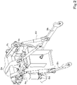
- the lifting device 8 includes the lift arm 8a, the lower linkage 8b, the top linkage 8c, the lift rod 8d, and the lift cylinder 8e.
- a front end portion of the lift arm 8a is supported swingably upward or downward on a rear upper portion of a case (transmission case) in which the transmission 5 is housed.
- the lift arm 8a swings (rises and lowers) by driving of the lift cylinder 8e.
- the lift cylinder 8e is constituted of a hydraulic cylinder.
- the lift cylinder 8e is connected to a hydraulic pump through a control valve 36.
- the control valve 36 is a solenoid valve. The control valve 36 extends and contracts the lift cylinder 8e.
- a front end portion of the lower linkage 8b is supported swingably upward or downward on a rear lower portion of the transmission 5.
- a front end portion of the top linkage 8c is supported swingably upward or downward on a rear portion of the transmission 5 above the lower linkage 8b.
- the lift rod 8d couples the lift arm 8a and the lower linkage 8b to each other.
- the working device 2 is coupled to a rear portion of the lower linkage 8b and a rear portion of the top linkage 8c.
- the lift cylinder 8e is driven (extended or contracted)
- the lift arm 8a rises or lowers
- the lower linkage 8b coupled to the lift arm 8a through the lift rod 8d rises or lowers. Accordingly, the working device 2 swings upward or downward (lifts or lowers) about a front portion of the lower linkage 8b serving as a fulcrum.
- the tractor 1 includes a steering device 29.
- the steering device 29 includes a steering wheel 30, a rotation shaft (steering shaft) 31 rotatable along with rotation of the steering wheel 30, and an assist mechanism (power steering mechanism) 32 that assists steering of the steering wheel 30.
- the assist mechanism 32 incudes a hydraulic pump 33, a control valve 34 to which a hydraulic fluid ejected from the hydraulic pump 33 is supplied, and a steering cylinder 35 operable by the control valve 34.
- the control valve 34 is a solenoid valve operable in accordance with a control signal.
- the control vale 34 is, for example, a 3-position switching valve switchable by, for example, movement of a spool.
- the control valve 34 is also switchable by steering of the steering shaft 31.
- the steering cylinder 35 is connected to an arm (knuckle arm) for changing the direction of the front wheels 7F.
- a switching position and an opening degree of the control valve 34 are switched in response to the operation of the steering wheel 30, and the steering cylinder 35 extends or contracts leftward or rightward according to the switching position and the opening degree of the control valve 34. Accordingly, a steering direction of the front wheels 7F can be changed.
- the steering device 29 described above is merely an example, and the configuration of the steering device 29 is not limited to the above-described configuration.
- the tractor 1 includes a positioning device 40.
- the positioning device 40 is capable of detecting its own position (positioning information including its latitude and longitude) using a satellite positioning system (positioning satellite) such as the D-GPS, the GPS, the GLONASS, the BeiDou, the Galileo, or the QZSS. That is, the positioning device 40 receives a satellite signal (e.g., a position of the positioning satellite, a transmission time, or correction information) transmitted from the positioning satellite and detects the position (e.g., the latitude and longitude) of the tractor 1, that is, the vehicle body position on the basis of the satellite signal.
- the positioning device 40 includes a receiver 41 and an inertial measurement unit (IMU) 42.
- IMU inertial measurement unit
- the receiver 41 includes, for example, an antenna and receives a satellite signal transmitted from the positioning satellite.
- the receiver 41 is attached to the traveling vehicle body 3 separately from the inertial measurement unit 42.
- the receiver 41 is attached to the traveling vehicle body 3, specifically, to the cabin 9.
- An attached location of the receiver 41 is not limited to the location in the embodiment.
- the inertial measurement unit 42 includes, for example, an acceleration sensor that detects an acceleration or a gyroscopic sensor that detects an angular velocity.
- the inertial measurement unit 42 is provided under the traveling vehicle body 3, for example, under the operator's seat 10 and can detect roll, pitch, and yaw angles of the traveling vehicle body 3.
- the tractor 1 includes a display device 50.
- the display device 50 includes a control unit 51, a display unit 52, and a storage unit 53.
- the control unit 51 is constituted of, for example, a CPU or an electric or electronic circuit and performs various control operations related to the display device 50.
- the display unit 52 is constituted of, for example, a liquid crystal panel, a touch panel, or another panel and display various pieces of information.
- the storage unit 53 is constituted of, for example, a nonvolatile memory.
- an application program for assisting work of the tractor 1 is stored in the storage unit 53.
- the display device 50 functions as a work assistance apparatus that assists work.
- the control unit 51 which is hardware, executes a process as the work assistance apparatus.
- the display device (work assistance apparatus) 50 includes a map registration unit 51A.
- the map registration unit 51A registers an outline of a predetermined agricultural field, for example, a position corresponding to the outline of the predetermined agricultural field.
- the map registration unit 51A displays a map registration screen M1 on the display unit 52.
- a map MP1 including an agricultural field, a vehicle body position VP1 of the tractor 1, and agricultural field identification information such as an agricultural field name or an agricultural field management number are displayed on the map registration screen M1.
- Positional information such as the latitude and longitude is associated, in addition to image data representing the agricultural field, with the map MP1.
- the current vehicle body position VP1 detected by the positioning device 40 when the tractor 1 circles around is displayed on the map registration screen M1.
- a registration button 55 displayed on the map registration screen M1 is selected after the tractor 1 finishes circling around inside the agricultural field, as illustrated in FIG.
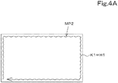
- the map registration unit 51A sets, as an outline (outer shape) HI of the agricultural field, a traveling track K1 obtained from a plurality of vehicle body positions of the tractor 1 circling around and registers an agricultural field map MP2 indicated by the outline HI together with the agricultural field identification information.
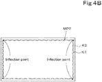
- the map registration unit 51A may register, as the outline H1 of the agricultural field (agricultural field map MP2), an outline K2 connecting inflection points calculated from the traveling track indicated by the vehicle body positions VP1.
- the map registration unit 51A may register, as the outline H1 (agricultural field map MP2), an outline K3 connecting corners of the agricultural field designated by, for example, a driver using a switch provided on the tractor 1 when the tractor 1 circles around.
- the agricultural field registration methods described above are merely examples, and the registration method is not limited thereto.
- the outline of the agricultural field, that is, the agricultural field map MP2 may be data indicated by a position (latitude and longitude), data indicated by a coordinate system (X and Y axes), or data indicated by another expression.
- the storage unit 53 stores the agricultural field map MP2 indicating the outline (outer shape) registered by the map registration unit 51A. That is, the storage unit 53 stores the agricultural field map MP2, that is, data indicating the outline of the agricultural field (data for representing a specified agricultural field).
- the display device (work assistance apparatus) 50 includes an area setting unit 51D.
- the area setting unit 51D sets a work area A2.
- the area setting unit 51D displays a work setting screen M2 on the display unit 52.
- the work setting screen M2 includes an agricultural field input portion 80 and an agricultural field display portion 81.
- Agricultural field identification information such as the agricultural field name or the agricultural field management number can be input to the agricultural field input portion 80.
- the agricultural field display portion 81 displays the agricultural field map MP2 indicating a predetermined agricultural field corresponding to the agricultural field identification information input to the agricultural field input portion 80.
- the area setting unit 51D invokes, from the storage unit 53, the agricultural field map MP2 corresponding to the agricultural field identification information input to the agricultural field input portion 80 and displays, on the agricultural field display portion 81, the agricultural field map MP2 transmitted from the storage unit 53.
- the area setting unit 51D displays the work area A2 except a turning area A1 on the agricultural field map MP2 displayed on the agricultural field display portion 81.
- the area setting unit 51D sets, as the work area A2, an area surrounded by an outline H2 that is offset inward by the turning width W1 from the outline H1 of the agricultural field map MP2.
- the work area A2 may be set on the agricultural field map MP2 displayed on the agricultural field display portion 81 by designating the position of the outline of the work area A2 on the agricultural field map MP2 using, for example, a pointer.
- the storage unit 53 stores data of the agricultural field map MP2 with the work area A2 set thereon (data indicating the position of the work area A2).
- the display device (work assistance apparatus) 50 includes a route creation unit 51B.
- the route creation unit 51B refers to the agricultural map MP2 registered in the storage unit 53 and creates a traveling route (planned traveling route) L1 for the traveling vehicle body 3 on the agricultural field map MP2.
- the route creation unit 51B displays a route setting screen M3 on the display unit 52.
- the planned traveling route L1 can be set at least in the work area A2 in the agricultural field.
- the route setting screen M3 includes a route display portion 85 that displays the planned traveling route L1 and a width input portion 86.
- a work width W2 of the working device 2 is a width (a work execution width) by which the working device 2 performs work on the ground such as an agricultural field. In the case where the working device 2 spreads the material onto the agricultural field, the work width W2 is a spreading width by which the material is supplied.
- a fertilizer spreading width corresponds to the work width W2.
- a chemical spraying width corresponds to the work width W2.
- a planting width by which seedlings can be planted into the agricultural field in one operation cycle corresponds to the work width.
- a seeding width corresponds to the work width W2.
- Ground work means agricultural work performed on an agricultural field and a crop planted on the agricultural field. Examples of the ground work include seedling planting, irrigation, chemical spraying, fertilizer spreading (fertilizer application), scattering of seeds (seeding), compaction, soil covering, ridge forming, tilling, and groove forming.
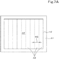
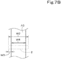
- the route creation unit 51B When the route creation unit 51B acquires the work width W2, as illustrated in FIG. 7A , the route creation unit 51B divides the work area A2 with the work width W2 in the longitudinal or lateral direction to create, inside the work area A2, a plurality of unit work sections A3 where the working device 2 performs the work. That is, the route creation unit 51B creates, inside the work area A2, the plurality of unit work sections A3 each having the same width as the work width W2. As illustrated in FIG. 7B , the route creation unit 51B may create, inside the work area A2, a plurality of unit work sections A3 each having a width W4 obtained by subtracting an overlap width W3 from the work width W2. The overlap width W3 can be input on the route setting screen M3. That is, the route creation unit 51B sets, as the unit work section A3, a minimum unit area where the working device 2 performs the work on the agricultural field when the traveling vehicle body 3 with the working device 2 coupled thereto is caused to travel.
- the route creation unit 51B creates, for each unit work section A3 on the agricultural field map MP2, a straight-ahead section (straight-ahead route) L1a on which the traveling vehicle body 3 travels straight ahead. That is, the route creation unit 51B, for example, creates the straight-ahead route L1a having a straight shape and extending between opposite ends in the longitudinal direction of the unit work section A3, that is, extending between opposite sides, in the longitudinal direction of the unit work section A3, of a boundary X1 between the turning area A1 and the work area A2, on a center in the width direction of the unit work section A3.
- the route creation unit 51B creates a turning section (turning rout) L1b connecting ends of straight-ahead routes L1a adjoining each other. That is, the route creation unit 51B creates the turning route L1b at least in the turning area A1.
- the route creation unit 51B is capable of associating the planned traveling route L1 with the vehicle speed (moving speed) of the tractor 1 (traveling vehicle body 3). For example, a vehicle speed input portion for inputting the vehicle speed is provided on the route setting screen M3, and the vehicle speed is input to the vehicle speed input portion.
- the route creation unit 51B associates the straight-ahead route L1a with the vehicle speed input to the vehicle speed input portion.
- the planned traveling route L1 (the straight-ahead route L1a and the turning route L1b) created by the route creation unit 51B is stored in the storage unit 53.
- the display device (work assistance apparatus) 50 includes a work setting unit 51H.
- the work setting unit 51H sets a work start and a work end in the working device 2. As illustrated in FIG. 9A , the work setting unit 51H sets a work start position STn and a work end position ETn at the boundary X1 between the work area A2 and the turning area A1. Alternatively, the work setting unit 51H sets the work start position STn and the work end position ETn on the planned traveling route L1.
- the work start positions STn and the work end positions ETn are aligned along the boundary X1.
- at least the work start position STn and the work end position ETn that are adjacent to each other are arranged side by side at the same position in the fore-and-aft direction of the traveling vehicle body 3 (working device 2).
- the work setting unit 51H can set the work start position STn and the work end position ETn on the basis of the type of the working device 2. Specifically, in a case where the working device 2 includes a plurality of working parts 101, the work set unit 51H sets the work start position STn and the work end position ETn adjoining each other at different positions in the fore-and-aft direction of the traveling vehicle body 3 (working device 2) according to the plurality of working parts 101.
- the display device (work assistance apparatus) 50 includes an information acquisition unit 511.
- the information acquisition unit 511 acquires information about the plurality of working parts 101 included in the working device 2.
- the information acquisition unit 511 displays a machine setting screen M10 for inputting, for example, information of the working parts 101 of the working device 2.
- the machine setting screen M10 includes a figure D1 representing the tractor (work vehicle) 1, a figure D2 representing the working device 2, a figure D3 representing the positioning device 40, a figure D4 representing the working part 101 on the front side (front working part), and a figure D5 representing the working part 101 on the rear side (rear working part).
- the working part 101 located on the front side may be referred to as "front working part 101K”
- the working part 101 located on the rear side may be referred to as "rear working part 101L”.
- the machine setting screen M10 further includes a first input portion 121 for inputting a first distance Y1, and a second input portion 122 for inputting a second distance Y2.
- the distance Y1 between the positioning device 40 and the front working part 101K located on the front side of the working device 2 in the fore-and-aft direction (traveling direction) is input to the first input portion 121.
- the distance Y2 between the front working part 101K and the rear working part 101L located rearward of the front working part 101K is input to the second input portion 122.
- the information acquisition unit 51I acquires, as the information about the plurality of working parts 101, the distance Y2 between the front working part 101K and the rear working part 101L located rearward of the front working part 101K.
- the positioning device 40 or the controller 60 can calculate a position of the front working part 101K (front working part position) from the distance Y1 input to the first input portion 121. Further, the positioning device 40 or the controller 60 can calculate a position of the rear working part 101L (rear working part position) from the distance Y1 input to the first input portion 121 and the distance Y2 input to the second input portion 122.
- the working device 2 can be raised or lowered or driving of the working device 2 can be started or stopped according to the front working part position and the rear working part position.
- an operator selects the front working part 101K and the rear working part 101L at least according to work and inputs the distances Y1 and Y2 respectively to the first input portion 121 and the second input portion 122 as described above according to the work.
- the first working part 101a and the fifth working part 101e which are respectively located on the frontmost side and the rearmost side among the working parts capable of stopping work (the first working part 101a, the second working part 101b, and the fifth working part 101e)
- the distance Y1 and the distance Y2 may be respectively input to the first input portion 121 and the second input portion 122 according to the positional relationship between the first working part 101a and the fifth working part 101e.
- the first working part 101a located on the frontmost side among the plurality of working parts 101 is selected as the front working part 101K
- the sixth working part 101f located on the rearmost side among the plurality of working parts 101 is selected as the rear working part 101L.
- the present invention is not limited thereto.
- the position of the positioning device 40, the position of the front working part 101K, and the position of the rear working part 101L may be designated on the machine setting screen M10 using, for example, a pointer, and the work setting unit 51H may obtain the first distance Y1 and the second distance Y2 from the designated positions.
- the work setting unit 51H sets the work start position STn and the work end position ETn at different positions on the basis of the second distance Y2.
- the work start position STn and the work end position ETn that are adjacent to each other can be offset from each other in the traveling direction of the working device 2 (the fore-and-aft direction of the working device 2) by the second distance Y2 between the fertilizer spreading nozzle (the first working part 101a) that sprays the fertilizer and the compacting roller (the sixth working part 101f).
- the work start position STn and the work end position ETn are set on the planned traveling route L1 (straight-ahead route L1an) with the turning area A1 and the working area A2 remaining unchanged.
- the work setting unit 51H may shift the work area A2 with the width of the unit work section A3 to the turning area A1 by at least the second distance Y2 and may set the work start position STn and the work end position ETn on the boundary X1 between the work area A2 and the turning area A1.
- the tractor 1 includes a controller 60.
- the controller 60 controls, for example, a traveling system and a work system of the tractor 1.
- An operation changeover switch 65 is connected to the controller 60.
- the operation changeover switch 65 is switchable between ON and OFF.
- the operation changeover switch 65 is capable of setting the controller 60 to an automatic operation mode when the operation changeover switch 65 is ON and capable of setting the controller 60 to a manual operation mode when the operation changeover switch 65 is OFF.
- the controller 60 includes an automatic operation control unit 63.
- the automatic operation control unit 63 is constituted of, for example, an electric or electronic circuit provided on the controller 60 or a program stored in a CPU.
- the automatic operation control unit 63 controls the automatic operation of the traveling vehicle body 3.
- the automatic operation control unit 63 starts the automatic operation when the controller 60 is in the automatic operation mode.
- the automatic operation control unit 63 maintains a rotation angle of the steering shaft (rotation shaft) 31.
- the deviation between the vehicle body position and the planned traveling route L1 is equal to or larger than the threshold and the tractor 1 is located leftward of the planned traveling route L1
- the automatic operation control unit 63 rotates the steering shaft 31 so that the steering direction of the tractor 1 becomes the rightward direction.
- the automatic operation control unit 63 rotates the steering shaft 31 so that the steering direction of the tractor 1 becomes the leftward direction.
- the steering angle of the steering device 29 is changed on the basis of the deviation between the vehicle body position and the planned traveling route L1.
- the automatic operation control unit 63 may set the steering angle so that the angle becomes zero (the vehicle body azimuth F1 coincides with the azimuth of the planned traveling route L1).
- the automatic operation control unit 63 may set the final steering angle in the automatic operation on the basis of the steering angle obtained on the basis of the deviation (position deviation) and the steering angle obtained on the basis of the azimuth (azimuth deviation).
- the setting of the steering angle in the automatic operation in the above embodiment is merely an example, and the setting of the steering angle is not limited thereto.
- the automatic operation control unit 63 automatically changes, for example, a speed-shift stage of the speed shifter or a rotation speed of the prime mover so that the current vehicle speed of the tractor 1 coincides with a vehicle speed corresponding to the planned traveling route L1.
- the lifting device 8 raises or lowers the working device 2 on the basis of the work start position STn and the work end position ETn changed by the work setting unit 51H. Further, the automatic operation control unit 63 controls the working device 2 on the basis of the work start position STn and the work end position ETn changed by the work setting unit 51H.
- the automatic operation control unit 63 causes the lifting device 8 to raise the working device 2 when the working device 2 passes the work end position ETn under the condition where the tractor 1 travels along the straight-ahead route L1a by the automatic operation with the working device 2 kept lowered (under the condition where the working device 2 performs the ground work).
- the automatic operation control unit 63 causes the lifting device 8 to lower the working device 2 when the working device 2 passes the work start position STn under the condition where the tractor 1 travels at least along the turning route L1b by the automatic operation with the working device 2 kept raised. Further, the automatic operation control unit 63 stops driving of the working device 2 when the working device 2 passes the work end position ETn under the condition where the ground work is performed. The automatic operation control unit 63 starts driving of the working device 2 (starts work of the working device 2) when the working device 2 passes the work start position STn under the condition where the tractor 1 travels at least along the turning route L1b by the automatic operation.
- the automatic operation control unit 63 outputs a raising signal to the control valve 36 to raise the working device 2 at a point in time when the compacting roller (the sixth working part 101f) passes the work end position ETn (when a locus of the rear working part position crosses the work end position ETn) under the condition where the ground work is performed. Further, the automatic operation control unit 63 stops driving of the plurality of driving devices (the feeder 104, the driving mechanism 105, and the feeder 112) provided on the working device 2 at a point in time when the compacting roller (the sixth working part 101f) passes the work end position ETn.
- the automatic operation control unit 63 may stop driving of the plurality of driving devices (the feeder 104, the driving mechanism 105, and the feeder 112) by outputting a stop signal to each of the driving devices or may stop the plurality of driving devices by switching a PTO clutch 125, the PTO clutch 125 being switchable between an engaged state where power of a PTO shaft is transmitted to the working device 2 and a disengaged state where power of the PTO shaft is not transmitted to the working device 2, from the engaged state to the disengaged state.
- the automatic operation control unit 63 lowers the working device 2 at a point in time when the fertilizer spreading nozzle (the first working part 101a) passes the work start position STn (when a locus of the front working device position crosses the work start position STn) in traveling from the turning route L1b to the straight-ahead route L1a. Further, the automatic operation control unit 63 outputs a driving signal to the feeder 104 and the driving mechanism 105 to drive the feeder 104, thereby starting tilling and fertilizer spreading, at a point in time when the fertilizer spreading nozzle (the first working device 101a) passes the work start position STn in traveling from the turning route L1b to the straight-ahead route L1a.
- the automatic operation control unit 63 outputs a driving signal to the feeder 112 to drive the feeder 104, thereby starting work relating to the compacting roller (the sixth working part 101f), that is, starting seeding through the seeding nozzle, at a point in time when the fertilizer spreading nozzle (the first working device 101a) advances a predetermined distance after passing the work start position STn, for example, at a point in time when the fertilizer spreading nozzle advances less than the second distance Y2 from the work start position STn.
- the automatic operation control unit 63 may monitor the distance between the rear working part position and the work end position ETn during the automatic operation and may perform control taking the responsivity of the lifting device 8 into consideration so that the raising of the working device 2 is actually started when the rear working part 101L reaches the work end position ETn. Similarly, the automatic operation control unit 63 may monitor the distance between the front working part position and the work start position STn during the automatic operation and may perform control taking the responsivity of the lifting device 8 into consideration so that the lowering of the working device 2 is actually completed when the front working part 101K reaches the work start position STn.
- the above embodiment describes the composite device including the plurality of working parts 101a to 101f.
- the composite device includes at least two working devices (the fertilizer spreader and the seeder) as described above, one working device (the fertilizer spreader) and the other working device (the seeder) may be regarded as working parts.
- fertilizer spreader 101K corresponds to the front working part 101K
- seeder 101L corresponds to the rear working part 101L.
- front working part 101K is the fertilizer spreader 101K
- rear working part 101L is the seeder 101L
- the first distance Y1 between the positioning device 40 and a front end 162 of the fertilizer spreader 101K is input to the first input portion 121 of the machine setting screen M10.
- the second distance Y2 between the front end 162 of the fertilizer spreader 101K and a rear end 161 of the seeder 101L is input to the second input portion 122.
- the work setting unit 51H sets the work start position STn and the work end position ETn on the basis of the second distance Y2 using the method described above.
- the automatic operation control unit 63 causes the lifting device 8 to raise the fertilizer spreader 101K and the seeder 101L when the rear end 161 of the seeder 101L passes the work end position ETn under the condition where the tractor 1 travels along the straight-ahead route L1a by the automatic operation with the fertilizer spreader 101K and the seeder 101L kept lowered (under the condition where the ground work is performed). As illustrated in FIG. 13A , the automatic operation control unit 63 causes the lifting device 8 to raise the fertilizer spreader 101K and the seeder 101L when the rear end 161 of the seeder 101L passes the work end position ETn under the condition where the tractor 1 travels along the straight-ahead route L1a by the automatic operation with the fertilizer spreader 101K and the seeder 101L kept lowered (under the condition where the ground work is performed). As illustrated in FIG.
- the automatic operation control unit 63 causes the lifting device 8 to lower the fertilizer spreader 101K and the seeder 101L when the front end 162 of the fertilizer spreader 101K passes the work start position STn under the condition where the tractor 1 travels at least along the turning route L1b by the automatic operation with the working device 2 kept raised. Further, the automatic operation control unit 63 stops driving of the fertilizer spreader 101K and the seeder 101L when the rear end of the seeder 101L passes the work end position ETn under the condition where the ground work is performed.
- the automatic operation control unit 63 starts driving of the fertilizer spreader 101K (starts work of the fertilizer spreader 101K) when the front end 162 of the fertilizer spreader 101K passes the work start position STn under the condition where the tractor 1 travels at least along the turning route L1b by the automatic operation.
- the automatic operation control unit 63 drives the seeder 101L at a point in time when the front end 162 of the fertilizer spreader 101K advances a predetermined distance after passing the work start position STn, for example, at a point in time when the front end 162 of the fertilizer spreader 101K advances less than the second distance Y2 from the work start position STn.
- the work vehicle 1 includes the traveling vehicle body 3, the coupling device capable of coupling the working device 2 to the traveling vehicle body 3, the working device 2 including the plurality of working parts 101 to the traveling vehicle body 3, the automatic operation control unit 63 that automatically operates the traveling vehicle body 3 on the basis of the planned traveling route L1, and the work setting unit 51H that sets the work start position STn and the work end position ETn for the working device 2 at different positions on the basis of the plurality of working parts 101.
- the work start position STn and the work end position ETn can be set at different positions.
- the working device 2 is long in the fore-and-aft direction and the working parts 101 are thus apart from each other, it is possible to reduce the possibility of presence of a place where at least one of the working parts 101 has not performed work (unworked place). That is, even when the work vehicle 1 performs work using the working device including the plurality of working parts 101 while traveling, the work can be accurately performed at an intended location.
- the work vehicle 1 includes the area setting unit 51D that sets the work area A2 where the working device 2 performs work and the turning area A1 where the traveling vehicle body 3 is turned around.
- the work setting unit 51D sets the work start position STn and the work end position ETn at the boundary X1 between the work area A2 and the turning area A1. This enables the plurality of working parts 101 to start work on the boundary X1 and to end work on the boundary X1 as accurately as possible.
- the work vehicle 1 includes the route creation unit 51B that creates the planned traveling route L1 for the traveling vehicle body 3.
- the work setting unit 51H sets the work start position STn and the work end position ETn for the working device 2 on the planned traveling route L1 on the basis of the plurality of working parts 101. This makes it easy to perform the traveling of the tractor 1 (working device 2) on the planned traveling route L1 set by the route creation unit 51B in conjunction with the work start at the work start position STn and the work end at the work end position ETn. Thus, the automatic operation can be efficiently performed.
- the work setting unit 51H sets the work end position ETn according to the position of the rear working part 101L that is the working part 101 located on the rear side among the plurality of working parts 101. This enables, among the plurality of working parts 101, the rear working part 101L to perform work up to the work end position ETn set by the work setting unit 51H.
- the work setting unit 51H sets the work start position STn according to the position of the front working part 101K that is the working part 101 located on the front side among the plurality of working parts 101. This enables, among the plurality of working parts 101, the front working part 101K to start work at the work start position STn set by the work setting unit 51H.
- the coupling device is the lifting device 8 that raises and lowers the working device 2, and raises and lowers the working device 2 on the basis of the work start position STn and the work end position ETn changed by the work setting unit 51H. Accordingly, the lifting device 8 can stably raise and lower the working device 2 even when the work start position STn and the work end positions ETn are set at different positions.
- the coupling device raises the working device 2 when the working device 2 passes the work end position ETn and lowers the working device 2 when the working device 2 passes the work start position STn. Accordingly, the work can be ended by raising the working device 2 at the work end position ETn, and the work can be started by lowering the working device 2 at the work start position STn.
- the work vehicle 1 includes the controller 60 that controls the working device 2 on the basis of the work start position STn and the work end position ETn changed by the work setting unit 51H. Accordingly, the controller 60 can stably start and end the work of the working device 2.
- the controller 60 stops work of the rear working part 101L that is the working part 101 located on the rear side among the plurality of working parts 101 when the rear working part 101L passes the work end position ETn. Accordingly, when the tractor 1 (working device 2) advances beyond the work end position ETn, the position where the rear working part 101L ends the work can be made as constant as possible.
- the controller 60 starts work of the front working part 101K that is the working part 101 located on the front side among the plurality of working parts 101 when the front working part 101K passes the work start position STn. Accordingly, in a case where the plurality of working partworking units 101 are present, takeover to work performed after the work of the front working part 101K can be smoothly performed by starting the work of the front working part 101K prior to the work of the rear working part 101L.
- the work setting unit 51H sets the work start position STn according to the position of the front working part 101K that is the working part 101 located on the front side among the plurality of working parts 101 and sets the work end position ETn according to the position of the rear working part 101L that is the working part 101 located on the rear side among the plurality of working parts 101.
- the controller 60 starts work of the rear working part 101L at a point in time when the traveling vehicle body 3 advances a predetermined distance after the front working part 101K starts work at the work start position STn. Accordingly, in a case where the working device 2 incudes the front working part 101K and the rear working part 101L, takeover to the work of the rear working part 101L can be performed after the work of the front working part 101K is performed. In addition, it is possible to reduce waste caused by the work of the rear working part 101L starting too early.
- the plurality of working parts 101 perform different types of work on the ground. Accordingly, various types of work can be efficiently performed in a combined manner.
- the work assistance apparatus for the work vehicle 1 includes the information acquisition unit 511 that acquires information about the plurality of working parts 101 included in the working device 2 coupled to the traveling vehicle body 3, and the work setting unit 51H that sets the work start position STn and the work end position ETn for the working device 2 at different positions on the basis of the information about the plurality of working parts 101 acquired by the information acquisition unit 511. Accordingly, the work start position STn and the work end position ETn can be set at different positions. Thus, for example, even if the working device 2 is long in the fore-and-aft direction and the working parts 101 are thus apart from each other, it is possible to reduce the possibility of presence of a place where at least one of the working parts 101 has not performed work (unworked place). That is, even when the work vehicle 1 performs work using the working device including the plurality of working parts 101 while traveling, the work can be accurately performed at an intended location.
- the work assistance apparatus for the work vehicle 1 includes the area setting unit 51D that sets the work area A2 where the working device 2 performs work and the turning area A1 where the traveling vehicle body 3 is turned around.
- the work setting unit 51H sets the work start position STn and the work end position ETn at the boundary X1 between the work area A2 and the turning area A1. This enables the plurality of working parts 101 to start work on the boundary X1 and to end work on the boundary X1 as accurately as possible.
- the work assistance apparatus for the work vehicle 1 includes the route creation unit 51B that creates the planned traveling route L1 for the traveling vehicle body 3.
- the work setting unit 51H sets the work start position STn and the work end position ETn for the working device 2 on the planned traveling routeL1 on the basis of the plurality of working parts 101. This makes it easy to perform the traveling of the tractor 1 (working device 2) on the planned traveling route L1 set by the route creation unit 51B in conjunction with the work start at the work start position STn and the work end at the work end position ETn. Thus, the automatic operation can be efficiently performed.
- the above embodiment describes the automatic operation that causes the tractor 1 (traveling vehicle body 3) to travel while changing the vehicle speed along the planned traveling route.
- the automatic operation also includes automatic steering that automatically performs only steering of the tractor 1 (traveling vehicle body 3) along the planned traveling route and automatic steering in which, after a traveling reference route for creating a planned traveling route is registered, a driver operates a switch to cause the tractor 1 to travel along the planned traveling route parallel to the traveling reference route in any manner.
Landscapes
- Engineering & Computer Science (AREA)
- Life Sciences & Earth Sciences (AREA)
- Business, Economics & Management (AREA)
- General Physics & Mathematics (AREA)
- Human Resources & Organizations (AREA)
- Physics & Mathematics (AREA)
- Mechanical Engineering (AREA)
- Soil Sciences (AREA)
- Environmental Sciences (AREA)
- Strategic Management (AREA)
- Economics (AREA)
- Automation & Control Theory (AREA)
- Remote Sensing (AREA)
- Radar, Positioning & Navigation (AREA)
- Theoretical Computer Science (AREA)
- General Business, Economics & Management (AREA)
- Aviation & Aerospace Engineering (AREA)
- Tourism & Hospitality (AREA)
- Marketing (AREA)
- Quality & Reliability (AREA)
- Marine Sciences & Fisheries (AREA)
- Entrepreneurship & Innovation (AREA)
- Game Theory and Decision Science (AREA)
- Development Economics (AREA)
- Agronomy & Crop Science (AREA)
- Animal Husbandry (AREA)
- Operations Research (AREA)
- Mining & Mineral Resources (AREA)
- Health & Medical Sciences (AREA)
- General Health & Medical Sciences (AREA)
- Primary Health Care (AREA)
- Guiding Agricultural Machines (AREA)
- Lifting Devices For Agricultural Implements (AREA)
Abstract
Description
- The present invention relates to a work vehicle, such as a tractor, and a work assistance apparatus for the work vehicle.
- A technique disclosed in
Patent Document 1 is known as a technique to create a traveling path (work traveling line) for automatically operating a work vehicle such as a tractor. A work vehicle ofPatent Document 1 includes an acquisition unit that acquires positional data of an outer periphery of an agricultural field, and a work setting unit that sets, in the agricultural field, a work traveling line on which a traveling machine body travels on the basis of the positional data. - [Patent Document 1]
Japanese Unexamined Patent Publication No. 2018-39 - In
Patent Document 1, the work vehicle can create the work traveling line and can perform work while automatically traveling along the work traveling line. However, there is a possibility that the work can be performed only on a part of a target agricultural field and cannot be performed on the other part thereof depending on the type of a working device. - In view of the above problem, an object of the present invention is to provide a work vehicle capable of accurately performing work at an intended location even when the work vehicle performs the work using a working device including a plurality of working parts while traveling, and a work assistance apparatus for the work vehicle.
- Technical means of the present invention for solving the technical problem described above is characterized in the following points.
- A work vehicle includes: a traveling vehicle body; a coupling device capable of coupling a working device to the traveling vehicle body, the working device including a plurality of working parts; an automatic operation control unit configured to automatically operate the traveling vehicle body on the basis of a planned traveling route; and a work setting unit configured to set a work start position and a work end position for the working device at different positions on the basis of the plurality of working parts.
- The work vehicle further includes an area setting unit configured to set a work area where the working device performs work and a turning area where the traveling vehicle body turns. The work setting unit sets the work start position and the work end position at a boundary between the work area and the turning area.
- The work vehicle further includes a route creation unit configured to create the planned traveling route for the traveling vehicle body. The work setting unit sets the work start position and the work end position for the working device on the planned traveling route on the basis of the plurality of working parts.
- The plurality of working parts includes a rear working part disposed rearward in the working device, and the work setting unit sets the work end position according to a position of the rear working part.
- The plurality of working parts includes a front working part disposed forward in the working device, and the work setting unit sets the work start position according to a position of the front working part.
- The coupling device is a lifting device configured to raise and lower the working device on the basis of the work start position and the work end position changed by the work setting unit.
- The coupling device raises the working device when the working device passes the work end position, and the coupling device lowers the working device when the working device passes the work start position.
- The work vehicle further includes a controller configured to control the working device on the basis of the work start position and the work end position variably set by the work setting unit.
- The plurality of working parts include a rear working part disposed rearward in the working device, and the controller stops work by use of the rear working part when the rear working part passes the work end position.
- The plurality of working parts include a front working part disposed forward in the working device, and the controller starts work by use of the front working part when the front working part passes the work start position.
- The plurality of working parts include a front working part disposed forward in the working device, and the work setting unit sets the work start position according to a position of the front working part. The plurality of working parts include a rear working part disposed rearward in the working device, and the work setting unit sets the work end position according to a position of the rear working part. The controller starts work by use of the rear working part at a point in time when the traveling vehicle body advances a predetermined distance after the front working part starts work at the work start position.
- The plurality of working parts perform different types of work on the ground.
- A work assistance apparatus for a work vehicle includes: an information acquisition unit configured to acquire information about a plurality of working parts included in a working device coupled to a traveling vehicle body; and a work setting unit configured to set a work start position and a work end position for the working device at different positions on the basis of the information about the plurality of working parts acquired by the information acquisition unit.
- The work assistance apparatus for a work vehicle further includes an area setting unit configured to set a work area where the working device performs work and a turning area where the traveling vehicle body turns. The work setting unit sets the work start position and the work end position at a boundary between the work area and the turning area.
- A work assistance apparatus for a work vehicle includes a route creation unit configured to create a planned traveling route for the traveling vehicle body. The work setting unit sets the work start position and the work end position for the working device on the planned traveling route on the basis of the information about the plurality of working parts.
- In the work assistance apparatus for a work vehicle, the plurality of working parts include a rear working part disposed rearward in the working device, and the work setting unit sets the work end position according to a position of the rear working part.
- The plurality of working parts include a front working part disposed forward in the working device, and the work setting unit sets the work start position according to a position of a front working part.
- According to the present invention, even when a work vehicle performs work using a working device including a plurality of working parts while traveling, the work can be accurately performed at an intended location.
-
-
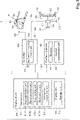
FIG. 1 is a block diagram of a work vehicle. -
FIG. 2 is a diagram illustrating a lifting device. -
FIG. 3 is a diagram illustrating an example of a map registration screen M1. -
FIG. 4A is a diagram illustrating obtaining an outline HI of an agricultural field (agricultural map MP2) from a traveling track K1. -
FIG. 4B is a diagram illustrating obtaining the outline HI of the agricultural field (agricultural map MP2) from inflection points of the traveling track K1. -
FIG. 4C is a diagram illustrating obtaining the outline HI (agricultural map MP2) by a switch operation during traveling. -
FIG. 5 is a diagram illustrating an example of a work setting screen M2. -
FIG. 6 is a diagram illustrating an example of a route setting screen M6. -
FIG. 7A is a diagram illustrating a unit work section A3 created on a work area A2. -
FIG. 7B is a diagram illustrating a unit work section A3 different from that inFIG. 7A . -
FIG. 8 is an explanatory diagram for explaining creation of a planned traveling route L1. -
FIG. 9A is a diagram illustrating a state where work start positions STn and work end positions ETn are aligned along a boundary X1. -
FIG. 9B is a diagram illustrating a state where the work start position STn and the work end position ETn that are adjacent to each other are offset from each other in a traveling direction. -
FIG. 9C is a diagram illustrating a state where the work start positions STn and the work end positions ETn are set at the boundary X1. -
FIG. 10 is a diagram illustrating an example of a machine setting screen M10. -
FIG. 11 is a diagram illustrating an example of an automatic operation. -
FIG. 12A is a diagram illustrating a state where a working device is raised when a rear working part passes the work end position ETn. -
FIG. 12B is a diagram illustrating a state where the working device is lowered when a front working part passes the work start position STn. -
FIG. 13A is a diagram illustrating a state where the working device is raised in a case where the front working part is a fertilizer spreader and the rear working part is a seeder. -
FIG. 13B is a diagram illustrating a state where the working device is lowered in the case where the front working part is the fertilizer spreader and the rear working part is the seeder. -
FIG. 14 is a diagram illustrating an example of a composite device. -
FIG. 15 is a side overall view of a tractor. - Hereinbelow, an embodiment of the present invention will be described with reference to the drawings.
-
FIG. 15 illustrates atractor 1, which is an example of a work vehicle. Although thetractor 1 will be described as an example of the work vehicle, the work vehicle is not limited to the tractor and may be a rice transplanter or a combine harvester. - As illustrated in
FIG. 15 , thetractor 1 includes a travelingvehicle body 3 including a travelingdevice 7, aprime mover 4, and atransmission 5. The travelingdevice 7 includesfront wheels 7F andrear wheels 7R. Thefront wheels 7F may be ones of a wheel type device or may be ones of a crawler type device. Also, therear wheels 7R may be ones of a wheel type device or may be ones of a crawler type device. Theprime mover 4 is, for example, a diesel engine or an electric motor. Thetransmission 5 transmits a driving force for driving the travelingdevice 7 while speed-shifting the driving force and capable of switching the traveling of the travelingdevice 7 between forward traveling and backward traveling. The travelingvehicle body 3 is provided with a cabin 9. An operator'sseat 10 is provided inside the cabin 9. - A coupling device is provided on a rear portion of the traveling
vehicle body 3. The coupling device is, for example, a swing drawbar that couples a workingdevice 2 to the travelingvehicle body 3 and does not raise and lower the workingdevice 2 or alifting device 8 that is constituted of, for example, a three-point linkage mechanism and raises and lowers the workingdevice 2. The workingdevice 2 is detachably attached to the coupling device. The travelingvehicle body 3 can tow the workingdevice 2 by coupling the workingdevice 2 to the coupling device. Examples of the workingdevice 2 include a tiller that performs tilling, a fertilizer spreader that spreads fertilizer, a transplanter that plants seedlings, an irrigation device that performs irrigation, an agricultural chemical spraying device that sprays agricultural chemicals, a seeder that scatters seeds, a mower that mows, for example, grass, a scattering device that scatters, for example, grass, a grass collecting device that collects, for example, grass, a shaping device that shapes, for example, grass, and a composite device that performs a plurality of types of work. -
FIG. 14 illustrates a composite device, which is an example of the workingdevice 2. The composite device illustrated inFIG. 14 includes a plurality of workingparts 101. The plurality of workingparts 101 include afirst working part 101a, asecond working part 101b, a third workingpart 101c, a fourth workingpart 101d, a fifth workingpart 101e, and a sixth workingpart 101f. Thefirst working part 101a, the second workingpart 101b, the third workingpart 101c, the fourth workingpart 101d, the fifth workingpart 101e, and the sixth workingpart 101f are arranged in this order from the front side to the rear side. Thefirst working part 101a is located on the frontmost side. The sixth workingpart 101f is located on the rearmost side. - The
first working part 101a is a fertilizer spreading nozzle that spreads or sprays a fertilizer charged into acontainer 102. Thefirst working part 101a is connected, through ahose 103, to afeeder 104 that feeds the fertilizer inside thecontainer 102. Thefirst working part 101a sprays, onto an agricultural field (ground), the fertilizer fed to thehose 103 by driving thefeeder 104. Thesecond working part 101b is a tilling tine that tills the agricultural field. Thesecond working part 101b is attached to arotation shaft 106 rotatable by adriving mechanism 105. Thesecond working part 101b rotates along with rotation of therotation shaft 106 to tilt the agricultural field by driving thedriving mechanism 105. Thethird working part 101c is a ground leveling cover disposed rearward of the second workingpart 101b. Thethird working part 101c levels the tilled ground. In the case of the composite device illustrated inFIG. 14 , the first workingpart 101a, the second workingpart 101b, and the third workingpart 101c constitute the fertilizer spreader. - The
fourth working part 101d is a groove forming disc that forms a groove. Thefifth working part 101e is a seeding nozzle that sows seeds charged into acontainer 110. Thefifth working part 101e is connected, through ahose 111, to afeeder 112 that feeds the seeds inside thecontainer 110. Thefifth working part 101e sows the seeds fed to thehose 111 by driving thefeeder 112 into the groove formed by the fourth workingpart 101d. The sixth workingpart 101f is a compacting roller that is rotatably supported and compacts at least a part with the seeds sowed therein. In the case of the composite device illustrated inFIG. 14 , the fourth workingpart 101d, the fifth workingpart 101e, and the sixth workingpart 101f constitute the seeder. - The
first working part 101a, the second workingpart 101b, the third workingpart 101c, the fourth workingpart 101d, the fifth workingpart 101e, and the sixth workingpart 101f are supported by aframe 115, and raised or lowered by thelifting device 8. That is, the fertilizer spreader and the seeder include theframe 115 and are supported by alift arm 8a, alower linkage 8b, atop linkage 8c, alift rod 8d, and alift cylinder 8e illustrated inFIG. 2 so as to be raised and lowered. Thefeeder 104, thedriving mechanism 105, and thefeeder 112 are driven (operated) by rotation of a PTO shaft projecting from the rear portion of the travelingvehicle body 3. - As illustrated in
FIG. 2 , thelifting device 8 includes thelift arm 8a, thelower linkage 8b, thetop linkage 8c, thelift rod 8d, and thelift cylinder 8e. A front end portion of thelift arm 8a is supported swingably upward or downward on a rear upper portion of a case (transmission case) in which thetransmission 5 is housed. Thelift arm 8a swings (rises and lowers) by driving of thelift cylinder 8e. Thelift cylinder 8e is constituted of a hydraulic cylinder. Thelift cylinder 8e is connected to a hydraulic pump through acontrol valve 36. Thecontrol valve 36 is a solenoid valve. Thecontrol valve 36 extends and contracts thelift cylinder 8e. - A front end portion of the
lower linkage 8b is supported swingably upward or downward on a rear lower portion of thetransmission 5. A front end portion of thetop linkage 8c is supported swingably upward or downward on a rear portion of thetransmission 5 above thelower linkage 8b. Thelift rod 8d couples thelift arm 8a and thelower linkage 8b to each other. The workingdevice 2 is coupled to a rear portion of thelower linkage 8b and a rear portion of thetop linkage 8c. When thelift cylinder 8e is driven (extended or contracted), thelift arm 8a rises or lowers, and thelower linkage 8b coupled to thelift arm 8a through thelift rod 8d rises or lowers. Accordingly, the workingdevice 2 swings upward or downward (lifts or lowers) about a front portion of thelower linkage 8b serving as a fulcrum. - As illustrated in
FIG. 1 , thetractor 1 includes asteering device 29. Thesteering device 29 includes asteering wheel 30, a rotation shaft (steering shaft) 31 rotatable along with rotation of thesteering wheel 30, and an assist mechanism (power steering mechanism) 32 that assists steering of thesteering wheel 30. Theassist mechanism 32 incudes ahydraulic pump 33, acontrol valve 34 to which a hydraulic fluid ejected from thehydraulic pump 33 is supplied, and asteering cylinder 35 operable by thecontrol valve 34. Thecontrol valve 34 is a solenoid valve operable in accordance with a control signal. Thecontrol vale 34 is, for example, a 3-position switching valve switchable by, for example, movement of a spool. Thecontrol valve 34 is also switchable by steering of the steeringshaft 31. Thesteering cylinder 35 is connected to an arm (knuckle arm) for changing the direction of thefront wheels 7F. - Thus, when the
steering wheel 30 is operated, a switching position and an opening degree of thecontrol valve 34 are switched in response to the operation of thesteering wheel 30, and thesteering cylinder 35 extends or contracts leftward or rightward according to the switching position and the opening degree of thecontrol valve 34. Accordingly, a steering direction of thefront wheels 7F can be changed. Thesteering device 29 described above is merely an example, and the configuration of thesteering device 29 is not limited to the above-described configuration. - The
tractor 1 includes apositioning device 40. Thepositioning device 40 is capable of detecting its own position (positioning information including its latitude and longitude) using a satellite positioning system (positioning satellite) such as the D-GPS, the GPS, the GLONASS, the BeiDou, the Galileo, or the QZSS. That is, thepositioning device 40 receives a satellite signal (e.g., a position of the positioning satellite, a transmission time, or correction information) transmitted from the positioning satellite and detects the position (e.g., the latitude and longitude) of thetractor 1, that is, the vehicle body position on the basis of the satellite signal. Thepositioning device 40 includes areceiver 41 and an inertial measurement unit (IMU) 42. Thereceiver 41 includes, for example, an antenna and receives a satellite signal transmitted from the positioning satellite. Thereceiver 41 is attached to the travelingvehicle body 3 separately from theinertial measurement unit 42. In the present embodiment, thereceiver 41 is attached to the travelingvehicle body 3, specifically, to the cabin 9. An attached location of thereceiver 41 is not limited to the location in the embodiment. - The
inertial measurement unit 42 includes, for example, an acceleration sensor that detects an acceleration or a gyroscopic sensor that detects an angular velocity. Theinertial measurement unit 42 is provided under the travelingvehicle body 3, for example, under the operator'sseat 10 and can detect roll, pitch, and yaw angles of the travelingvehicle body 3. - As illustrated in
FIG. 1 , thetractor 1 includes adisplay device 50. Thedisplay device 50 includes acontrol unit 51, adisplay unit 52, and astorage unit 53. Thecontrol unit 51 is constituted of, for example, a CPU or an electric or electronic circuit and performs various control operations related to thedisplay device 50. Thedisplay unit 52 is constituted of, for example, a liquid crystal panel, a touch panel, or another panel and display various pieces of information. Thestorage unit 53 is constituted of, for example, a nonvolatile memory. For example, an application program for assisting work of thetractor 1 is stored in thestorage unit 53. When the application program is started, thedisplay device 50 functions as a work assistance apparatus that assists work. Also when thedisplay device 50 functions as the work assistance apparatus, thecontrol unit 51, which is hardware, executes a process as the work assistance apparatus. - As illustrated in
FIG. 1 , the display device (work assistance apparatus) 50 includes amap registration unit 51A. Themap registration unit 51A registers an outline of a predetermined agricultural field, for example, a position corresponding to the outline of the predetermined agricultural field. As illustrated inFIG. 3 , when a predetermined operation is performed on thedisplay device 50, themap registration unit 51A displays a map registration screen M1 on thedisplay unit 52. - A map MP1 including an agricultural field, a vehicle body position VP1 of the
tractor 1, and agricultural field identification information such as an agricultural field name or an agricultural field management number are displayed on the map registration screen M1. Positional information such as the latitude and longitude is associated, in addition to image data representing the agricultural field, with the map MP1. When thetractor 1 enters the agricultural field and circles around inside the agricultural field, the current vehicle body position VP1 detected by thepositioning device 40 when thetractor 1 circles around is displayed on the map registration screen M1. When aregistration button 55 displayed on the map registration screen M1 is selected after thetractor 1 finishes circling around inside the agricultural field, as illustrated inFIG. 4A , themap registration unit 51A sets, as an outline (outer shape) HI of the agricultural field, a traveling track K1 obtained from a plurality of vehicle body positions of thetractor 1 circling around and registers an agricultural field map MP2 indicated by the outline HI together with the agricultural field identification information. - Alternatively, as illustrated in
FIG. 4B , themap registration unit 51A may register, as the outline H1 of the agricultural field (agricultural field map MP2), an outline K2 connecting inflection points calculated from the traveling track indicated by the vehicle body positions VP1. As illustrated inFIG. 4C , themap registration unit 51A may register, as the outline H1 (agricultural field map MP2), an outline K3 connecting corners of the agricultural field designated by, for example, a driver using a switch provided on thetractor 1 when thetractor 1 circles around. The agricultural field registration methods described above are merely examples, and the registration method is not limited thereto. The outline of the agricultural field, that is, the agricultural field map MP2 may be data indicated by a position (latitude and longitude), data indicated by a coordinate system (X and Y axes), or data indicated by another expression. - The
storage unit 53 stores the agricultural field map MP2 indicating the outline (outer shape) registered by themap registration unit 51A. That is, thestorage unit 53 stores the agricultural field map MP2, that is, data indicating the outline of the agricultural field (data for representing a specified agricultural field). - As illustrated in
FIG. 1 , the display device (work assistance apparatus) 50 includes anarea setting unit 51D. Thearea setting unit 51D sets a work area A2. - As illustrated in
FIG. 5 , when an operator (driver) performs a predetermined operation on the display device, thearea setting unit 51D displays a work setting screen M2 on thedisplay unit 52. The work setting screen M2 includes an agriculturalfield input portion 80 and an agriculturalfield display portion 81. Agricultural field identification information such as the agricultural field name or the agricultural field management number can be input to the agriculturalfield input portion 80. The agriculturalfield display portion 81 displays the agricultural field map MP2 indicating a predetermined agricultural field corresponding to the agricultural field identification information input to the agriculturalfield input portion 80. That is, thearea setting unit 51D invokes, from thestorage unit 53, the agricultural field map MP2 corresponding to the agricultural field identification information input to the agriculturalfield input portion 80 and displays, on the agriculturalfield display portion 81, the agricultural field map MP2 transmitted from thestorage unit 53. - On the agricultural field map MP2, when a turning width W1 is input to a turning
width input portion 82 and aturning setting button 83 is selected, thearea setting unit 51D displays the work area A2 except a turning area A1 on the agricultural field map MP2 displayed on the agriculturalfield display portion 81. For example, thearea setting unit 51D sets, as the work area A2, an area surrounded by an outline H2 that is offset inward by the turning width W1 from the outline H1 of the agricultural field map MP2. On the work setting screen M2, the work area A2 may be set on the agricultural field map MP2 displayed on the agriculturalfield display portion 81 by designating the position of the outline of the work area A2 on the agricultural field map MP2 using, for example, a pointer. - The
storage unit 53 stores data of the agricultural field map MP2 with the work area A2 set thereon (data indicating the position of the work area A2). - As illustrated in
FIG. 1 , the display device (work assistance apparatus) 50 includes aroute creation unit 51B. Theroute creation unit 51B refers to the agricultural map MP2 registered in thestorage unit 53 and creates a traveling route (planned traveling route) L1 for the travelingvehicle body 3 on the agricultural field map MP2. - As illustrated in
FIG. 6 , when an operator (driver) performs a predetermined operation on the display device, theroute creation unit 51B displays a route setting screen M3 on thedisplay unit 52. On the route setting screen M3, the planned traveling route L1 can be set at least in the work area A2 in the agricultural field. The route setting screen M3 includes aroute display portion 85 that displays the planned traveling route L1 and awidth input portion 86. A work width W2 of the workingdevice 2 is a width (a work execution width) by which the workingdevice 2 performs work on the ground such as an agricultural field. In the case where the workingdevice 2 spreads the material onto the agricultural field, the work width W2 is a spreading width by which the material is supplied. For example, in a case where the workingdevice 2 is a fertilizer spreader, a fertilizer spreading width corresponds to the work width W2. In a case where the workingdevice 2 is a chemical spraying device, a chemical spraying width corresponds to the work width W2. In a case where the workingdevice 2 is a seedling transplanter, a planting width by which seedlings can be planted into the agricultural field in one operation cycle corresponds to the work width. In a case where the workingdevice 2 is a seeder, a seeding width corresponds to the work width W2. Ground work means agricultural work performed on an agricultural field and a crop planted on the agricultural field. Examples of the ground work include seedling planting, irrigation, chemical spraying, fertilizer spreading (fertilizer application), scattering of seeds (seeding), compaction, soil covering, ridge forming, tilling, and groove forming. - When the
route creation unit 51B acquires the work width W2, as illustrated inFIG. 7A , theroute creation unit 51B divides the work area A2 with the work width W2 in the longitudinal or lateral direction to create, inside the work area A2, a plurality of unit work sections A3 where the workingdevice 2 performs the work. That is, theroute creation unit 51B creates, inside the work area A2, the plurality of unit work sections A3 each having the same width as the work width W2. As illustrated inFIG. 7B , theroute creation unit 51B may create, inside the work area A2, a plurality of unit work sections A3 each having a width W4 obtained by subtracting an overlap width W3 from the work width W2. The overlap width W3 can be input on the route setting screen M3. That is, theroute creation unit 51B sets, as the unit work section A3, a minimum unit area where the workingdevice 2 performs the work on the agricultural field when the travelingvehicle body 3 with the workingdevice 2 coupled thereto is caused to travel. - As illustrated in
FIG. 8 , theroute creation unit 51B creates, for each unit work section A3 on the agricultural field map MP2, a straight-ahead section (straight-ahead route) L1a on which the travelingvehicle body 3 travels straight ahead. That is, theroute creation unit 51B, for example, creates the straight-ahead route L1a having a straight shape and extending between opposite ends in the longitudinal direction of the unit work section A3, that is, extending between opposite sides, in the longitudinal direction of the unit work section A3, of a boundary X1 between the turning area A1 and the work area A2, on a center in the width direction of the unit work section A3. Theroute creation unit 51B creates a turning section (turning rout) L1b connecting ends of straight-ahead routes L1a adjoining each other. That is, theroute creation unit 51B creates the turning route L1b at least in the turning area A1. - The
route creation unit 51B is capable of associating the planned traveling route L1 with the vehicle speed (moving speed) of the tractor 1 (traveling vehicle body 3). For example, a vehicle speed input portion for inputting the vehicle speed is provided on the route setting screen M3, and the vehicle speed is input to the vehicle speed input portion. Theroute creation unit 51B associates the straight-ahead route L1a with the vehicle speed input to the vehicle speed input portion. The planned traveling route L1 (the straight-ahead route L1a and the turning route L1b) created by theroute creation unit 51B is stored in thestorage unit 53. - The display device (work assistance apparatus) 50 includes a
work setting unit 51H. Thework setting unit 51H sets a work start and a work end in the workingdevice 2. As illustrated inFIG. 9A , thework setting unit 51H sets a work start position STn and a work end position ETn at the boundary X1 between the work area A2 and the turning area A1. Alternatively, thework setting unit 51H sets the work start position STn and the work end position ETn on the planned traveling route L1. - Specifically, in a case where the planned traveling route L1 includes straight-ahead routes L1an (n = 1, 2, ... n, where the straight-ahead route L1a1 (n = 1) is closest to a work start point, and the straight-ahead route L1an (n = n) is closest to a work finish point), as illustrated in FIG. 8A, the
work setting unit 51H sets the work start position STn (n = 2, 4, 6 ...) at an end on one side (an end on the same side as the work finish point) of the even-numbered straight-ahead route L1an (n = 2, 4, 6 ...). Thework setting unit 51H sets the work start position STn (n = 1, 3, 5 ...) at an end on the other side (an end on the same side as the work start point) of the odd-numbered straight-ahead route L1an (n = 1, 3, 5 ...). - The
work setting unit 51H sets the work end position ETn (n = 1, 3, 5 ...) at an end on the one side (an end on the same side as the work finish point) of the odd-numbered straight-ahead route L1an (n = 1, 3, 5 ...). Thework setting unit 51H sets the work end position ETn (n = 2, 4, 6 ...) at an end on the other side (an end on the same side as the work start point) of the even-numbered straight-ahead route L1an (n = 2, 4, 6 ...). - That is, in
FIG. 9A , the work start positions STn and the work end positions ETn are aligned along the boundary X1.In other words, at least the work start position STn and the work end position ETn that are adjacent to each other are arranged side by side at the same position in the fore-and-aft direction of the traveling vehicle body 3 (working device 2). - The
work setting unit 51H can set the work start position STn and the work end position ETn on the basis of the type of the workingdevice 2. Specifically, in a case where the workingdevice 2 includes a plurality of workingparts 101, the work setunit 51H sets the work start position STn and the work end position ETn adjoining each other at different positions in the fore-and-aft direction of the traveling vehicle body 3 (working device 2) according to the plurality of workingparts 101. - As illustrated in
FIG. 1 , the display device (work assistance apparatus) 50 includes aninformation acquisition unit 511. Theinformation acquisition unit 511 acquires information about the plurality of workingparts 101 included in the workingdevice 2. - When a predetermined operation is performed on the display device (work assistance apparatus) 50, as illustrated in
FIG. 10 , theinformation acquisition unit 511 displays a machine setting screen M10 for inputting, for example, information of the workingparts 101 of the workingdevice 2. The machine setting screen M10 includes a figure D1 representing the tractor (work vehicle) 1, a figure D2 representing the workingdevice 2, a figure D3 representing thepositioning device 40, a figure D4 representing the workingpart 101 on the front side (front working part), and a figure D5 representing the workingpart 101 on the rear side (rear working part). For convenience of description, among the plurality of workingparts 101, the workingpart 101 located on the front side may be referred to as "front working part 101K", and the workingpart 101 located on the rear side may be referred to as "rear working part 101L". - The machine setting screen M10 further includes a
first input portion 121 for inputting a first distance Y1, and asecond input portion 122 for inputting a second distance Y2. - The distance Y1 between the
positioning device 40 and the front workingpart 101K located on the front side of the workingdevice 2 in the fore-and-aft direction (traveling direction) is input to thefirst input portion 121. The distance Y2 between the front workingpart 101K and therear working part 101L located rearward of the front workingpart 101K is input to thesecond input portion 122. The information acquisition unit 51I acquires, as the information about the plurality of workingparts 101, the distance Y2 between the front workingpart 101K and therear working part 101L located rearward of the front workingpart 101K. - The
positioning device 40 or thecontroller 60 can calculate a position of the front workingpart 101K (front working part position) from the distance Y1 input to thefirst input portion 121. Further, thepositioning device 40 or thecontroller 60 can calculate a position of therear working part 101L (rear working part position) from the distance Y1 input to thefirst input portion 121 and the distance Y2 input to thesecond input portion 122. The workingdevice 2 can be raised or lowered or driving of the workingdevice 2 can be started or stopped according to the front working part position and the rear working part position. - In the working device including the plurality of working
parts 101 such as the composite device, for example, an operator (driver) selects the front workingpart 101K and therear working part 101L at least according to work and inputs the distances Y1 and Y2 respectively to thefirst input portion 121 and thesecond input portion 122 as described above according to the work. For example, of the plurality of workingparts 101, the first workingpart 101a and the fifth workingpart 101e, which are respectively located on the frontmost side and the rearmost side among the working parts capable of stopping work (the first workingpart 101a, the second workingpart 101b, and the fifth workingpart 101e), may be selected as thefront working part 101K and therear working part 101L, respectively. Further, the distance Y1 and the distance Y2 may be respectively input to thefirst input portion 121 and thesecond input portion 122 according to the positional relationship between the first workingpart 101a and the fifth workingpart 101e. - In the present embodiment, description will be made assuming that, in the composite device illustrated in
FIG. 14 , the first workingpart 101a located on the frontmost side among the plurality of workingparts 101 is selected as thefront working part 101K, and the sixth workingpart 101f located on the rearmost side among the plurality of workingparts 101 is selected as therear working part 101L. - Although, in the above embodiment, the first distance Y1 between the
positioning device 40 and the front workingpart 101K and the second distance Y2 between the front workingpart 101K and therear working part 101L are respectively input to thefirst input portion 121 and thesecond input portion 122 on the machine setting screen M10, the present invention is not limited thereto. The position of thepositioning device 40, the position of the front workingpart 101K, and the position of therear working part 101L may be designated on the machine setting screen M10 using, for example, a pointer, and thework setting unit 51H may obtain the first distance Y1 and the second distance Y2 from the designated positions. - As illustrated in
FIG. 9B , when theinformation acquisition unit 511 acquires the second distance Y2, thework setting unit 51H sets the work start position STn and the work end position ETn at different positions on the basis of the second distance Y2. Thework setting unit 51H shifts the work start position STn (n = 2, 4, 6 ...) located on the same side as the work finish point illustrated inFIG. 9A to the turning area A1 by at least the second distance Y2. The straight-ahead route L1an (n = 2, 4, 6 ...) corresponding to the shifted work start position STn (n = 2, 4, 6 ...) is extended to the shifted work start position STn (n = 2, 4, 6 ...). - Further, as illustrated in
FIG. 9B , thework setting unit 51H shifts the work start position STn (n = 3, 5 ...) located on the same side as the work start point illustrated inFIG. 9A to the turning area A1 by at least the second distance Y2. The straight-ahead route L1an (n = 3, 5, 7 ...) corresponding to the shifted work start position STn (n = 3, 5, 7 ...) is extended to the shifted work start position STn (n = 3, 5 ...). - That is, the work start position STn and the work end position ETn that are adjacent to each other can be offset from each other in the traveling direction of the working device 2 (the fore-and-aft direction of the working device 2) by the second distance Y2 between the fertilizer spreading nozzle (the first working
part 101a) that sprays the fertilizer and the compacting roller (the sixth workingpart 101f). - In the above embodiment, the work start position STn and the work end position ETn are set on the planned traveling route L1 (straight-ahead route L1an) with the turning area A1 and the working area A2 remaining unchanged. However, as illustrated in
FIG. 9C , thework setting unit 51H may shift the work area A2 with the width of the unit work section A3 to the turning area A1 by at least the second distance Y2 and may set the work start position STn and the work end position ETn on the boundary X1 between the work area A2 and the turning area A1. - Next, the automatic operation will be described in detail.
- As illustrated in
FIG. 1 , thetractor 1 includes acontroller 60. Thecontroller 60 controls, for example, a traveling system and a work system of thetractor 1. Anoperation changeover switch 65 is connected to thecontroller 60. Theoperation changeover switch 65 is switchable between ON and OFF. Theoperation changeover switch 65 is capable of setting thecontroller 60 to an automatic operation mode when theoperation changeover switch 65 is ON and capable of setting thecontroller 60 to a manual operation mode when theoperation changeover switch 65 is OFF. - The
controller 60 includes an automaticoperation control unit 63. The automaticoperation control unit 63 is constituted of, for example, an electric or electronic circuit provided on thecontroller 60 or a program stored in a CPU. - The automatic
operation control unit 63 controls the automatic operation of the travelingvehicle body 3. The automaticoperation control unit 63 starts the automatic operation when thecontroller 60 is in the automatic operation mode. As illustrated inFIG. 11 , when a deviation between the vehicle body position and the planned traveling route L1 is smaller than a threshold under the condition where thetractor 1 performs the automatic operation, the automaticoperation control unit 63 maintains a rotation angle of the steering shaft (rotation shaft) 31. When the deviation between the vehicle body position and the planned traveling route L1 is equal to or larger than the threshold and thetractor 1 is located leftward of the planned traveling route L1, the automaticoperation control unit 63 rotates the steeringshaft 31 so that the steering direction of thetractor 1 becomes the rightward direction. When the deviation between the vehicle body position and the planned traveling route L1 is equal to or larger than the threshold and thetractor 1 is located rightward of the planned traveling route L1, the automaticoperation control unit 63 rotates the steeringshaft 31 so that the steering direction of thetractor 1 becomes the leftward direction. In the above embodiment, the steering angle of thesteering device 29 is changed on the basis of the deviation between the vehicle body position and the planned traveling route L1. However, when an azimuth (vehicle body azimuth) of the traveling direction of the tractor 1 (traveling vehicle body 3) differs from an azimuth of the planned traveling route L1, that is, when an angle of the vehicle body azimuth relative to the planned traveling route L1 is equal to or larger than a threshold, the automaticoperation control unit 63 may set the steering angle so that the angle becomes zero (the vehicle body azimuth F1 coincides with the azimuth of the planned traveling route L1). The automaticoperation control unit 63 may set the final steering angle in the automatic operation on the basis of the steering angle obtained on the basis of the deviation (position deviation) and the steering angle obtained on the basis of the azimuth (azimuth deviation). The setting of the steering angle in the automatic operation in the above embodiment is merely an example, and the setting of the steering angle is not limited thereto. - When the planned traveling route L1 and the vehicle speed are associated with each other, the automatic
operation control unit 63 automatically changes, for example, a speed-shift stage of the speed shifter or a rotation speed of the prime mover so that the current vehicle speed of thetractor 1 coincides with a vehicle speed corresponding to the planned traveling route L1. - As illustrated in
FIGS. 9B and9C , when the work start position STn and the work end position ETn are set at different positions in the travelling direction (the fore-and-aft direction of the traveling vehicle body 3), thelifting device 8 raises or lowers the workingdevice 2 on the basis of the work start position STn and the work end position ETn changed by thework setting unit 51H. Further, the automaticoperation control unit 63 controls the workingdevice 2 on the basis of the work start position STn and the work end position ETn changed by thework setting unit 51H. - As illustrated in
FIG. 12A , the automaticoperation control unit 63 causes thelifting device 8 to raise the workingdevice 2 when the workingdevice 2 passes the work end position ETn under the condition where thetractor 1 travels along the straight-ahead route L1a by the automatic operation with the workingdevice 2 kept lowered (under the condition where the workingdevice 2 performs the ground work). - As illustrated in
FIG. 12B , the automaticoperation control unit 63 causes thelifting device 8 to lower the workingdevice 2 when the workingdevice 2 passes the work start position STn under the condition where thetractor 1 travels at least along the turning route L1b by the automatic operation with the workingdevice 2 kept raised. Further, the automaticoperation control unit 63 stops driving of the workingdevice 2 when the workingdevice 2 passes the work end position ETn under the condition where the ground work is performed. The automaticoperation control unit 63 starts driving of the working device 2 (starts work of the working device 2) when the workingdevice 2 passes the work start position STn under the condition where thetractor 1 travels at least along the turning route L1b by the automatic operation. - More specifically, as illustrated in
FIG. 12A , the automaticoperation control unit 63 outputs a raising signal to thecontrol valve 36 to raise the workingdevice 2 at a point in time when the compacting roller (the sixth workingpart 101f) passes the work end position ETn (when a locus of the rear working part position crosses the work end position ETn) under the condition where the ground work is performed. Further, the automaticoperation control unit 63 stops driving of the plurality of driving devices (thefeeder 104, thedriving mechanism 105, and the feeder 112) provided on the workingdevice 2 at a point in time when the compacting roller (the sixth workingpart 101f) passes the work end position ETn. - The automatic
operation control unit 63 may stop driving of the plurality of driving devices (thefeeder 104, thedriving mechanism 105, and the feeder 112) by outputting a stop signal to each of the driving devices or may stop the plurality of driving devices by switching a PTO clutch 125, the PTO clutch 125 being switchable between an engaged state where power of a PTO shaft is transmitted to the workingdevice 2 and a disengaged state where power of the PTO shaft is not transmitted to the workingdevice 2, from the engaged state to the disengaged state. - As illustrated in
FIG. 12B , the automaticoperation control unit 63 lowers the workingdevice 2 at a point in time when the fertilizer spreading nozzle (the first workingpart 101a) passes the work start position STn (when a locus of the front working device position crosses the work start position STn) in traveling from the turning route L1b to the straight-ahead route L1a. Further, the automaticoperation control unit 63 outputs a driving signal to thefeeder 104 and thedriving mechanism 105 to drive thefeeder 104, thereby starting tilling and fertilizer spreading, at a point in time when the fertilizer spreading nozzle (thefirst working device 101a) passes the work start position STn in traveling from the turning route L1b to the straight-ahead route L1a. - The automatic
operation control unit 63 outputs a driving signal to thefeeder 112 to drive thefeeder 104, thereby starting work relating to the compacting roller (the sixth workingpart 101f), that is, starting seeding through the seeding nozzle, at a point in time when the fertilizer spreading nozzle (thefirst working device 101a) advances a predetermined distance after passing the work start position STn, for example, at a point in time when the fertilizer spreading nozzle advances less than the second distance Y2 from the work start position STn. - The automatic
operation control unit 63 may monitor the distance between the rear working part position and the work end position ETn during the automatic operation and may perform control taking the responsivity of thelifting device 8 into consideration so that the raising of the workingdevice 2 is actually started when therear working part 101L reaches the work end position ETn. Similarly, the automaticoperation control unit 63 may monitor the distance between the front working part position and the work start position STn during the automatic operation and may perform control taking the responsivity of thelifting device 8 into consideration so that the lowering of the workingdevice 2 is actually completed when the front workingpart 101K reaches the work start position STn. - The above embodiment describes the composite device including the plurality of working
parts 101a to 101f. However, in a case where the composite device includes at least two working devices (the fertilizer spreader and the seeder) as described above, one working device (the fertilizer spreader) and the other working device (the seeder) may be regarded as working parts. In this embodiment, "fertilizer spreader 101K" corresponds to thefront working part 101K, and "seeder 101L" corresponds to therear working part 101L. - Hereinbelow, the case where the
front working part 101K is thefertilizer spreader 101K, and therear working part 101L is theseeder 101L will be described. - As illustrated in
FIG. 10 , the first distance Y1 between thepositioning device 40 and afront end 162 of thefertilizer spreader 101K is input to thefirst input portion 121 of the machine setting screen M10. The second distance Y2 between thefront end 162 of thefertilizer spreader 101K and arear end 161 of theseeder 101L is input to thesecond input portion 122. - The
work setting unit 51H sets the work start position STn and the work end position ETn on the basis of the second distance Y2 using the method described above. - As illustrated in
FIG. 13A , the automaticoperation control unit 63 causes thelifting device 8 to raise thefertilizer spreader 101K and theseeder 101L when therear end 161 of theseeder 101L passes the work end position ETn under the condition where thetractor 1 travels along the straight-ahead route L1a by the automatic operation with thefertilizer spreader 101K and theseeder 101L kept lowered (under the condition where the ground work is performed). As illustrated inFIG. 13B , the automaticoperation control unit 63 causes thelifting device 8 to lower thefertilizer spreader 101K and theseeder 101L when thefront end 162 of thefertilizer spreader 101K passes the work start position STn under the condition where thetractor 1 travels at least along the turning route L1b by the automatic operation with the workingdevice 2 kept raised. Further, the automaticoperation control unit 63 stops driving of thefertilizer spreader 101K and theseeder 101L when the rear end of theseeder 101L passes the work end position ETn under the condition where the ground work is performed. The automaticoperation control unit 63 starts driving of thefertilizer spreader 101K (starts work of thefertilizer spreader 101K) when thefront end 162 of thefertilizer spreader 101K passes the work start position STn under the condition where thetractor 1 travels at least along the turning route L1b by the automatic operation. - The automatic
operation control unit 63 drives theseeder 101L at a point in time when thefront end 162 of thefertilizer spreader 101K advances a predetermined distance after passing the work start position STn, for example, at a point in time when thefront end 162 of thefertilizer spreader 101K advances less than the second distance Y2 from the work start position STn. - The
work vehicle 1 includes the travelingvehicle body 3, the coupling device capable of coupling the workingdevice 2 to the travelingvehicle body 3, the workingdevice 2 including the plurality of workingparts 101 to the travelingvehicle body 3, the automaticoperation control unit 63 that automatically operates the travelingvehicle body 3 on the basis of the planned traveling route L1, and thework setting unit 51H that sets the work start position STn and the work end position ETn for the workingdevice 2 at different positions on the basis of the plurality of workingparts 101. - According to this configuration, the work start position STn and the work end position ETn can be set at different positions. Thus, for example, even if the working
device 2 is long in the fore-and-aft direction and the workingparts 101 are thus apart from each other, it is possible to reduce the possibility of presence of a place where at least one of the workingparts 101 has not performed work (unworked place). That is, even when thework vehicle 1 performs work using the working device including the plurality of workingparts 101 while traveling, the work can be accurately performed at an intended location. - The
work vehicle 1 includes thearea setting unit 51D that sets the work area A2 where the workingdevice 2 performs work and the turning area A1 where the travelingvehicle body 3 is turned around. Thework setting unit 51D sets the work start position STn and the work end position ETn at the boundary X1 between the work area A2 and the turning area A1. This enables the plurality of workingparts 101 to start work on the boundary X1 and to end work on the boundary X1 as accurately as possible. - The
work vehicle 1 includes theroute creation unit 51B that creates the planned traveling route L1 for the travelingvehicle body 3. Thework setting unit 51H sets the work start position STn and the work end position ETn for the workingdevice 2 on the planned traveling route L1 on the basis of the plurality of workingparts 101. This makes it easy to perform the traveling of the tractor 1 (working device 2) on the planned traveling route L1 set by theroute creation unit 51B in conjunction with the work start at the work start position STn and the work end at the work end position ETn. Thus, the automatic operation can be efficiently performed. - The
work setting unit 51H sets the work end position ETn according to the position of therear working part 101L that is the workingpart 101 located on the rear side among the plurality of workingparts 101. This enables, among the plurality of workingparts 101, therear working part 101L to perform work up to the work end position ETn set by thework setting unit 51H. - The
work setting unit 51H sets the work start position STn according to the position of the front workingpart 101K that is the workingpart 101 located on the front side among the plurality of workingparts 101. This enables, among the plurality of workingparts 101, thefront working part 101K to start work at the work start position STn set by thework setting unit 51H. - The coupling device is the
lifting device 8 that raises and lowers the workingdevice 2, and raises and lowers the workingdevice 2 on the basis of the work start position STn and the work end position ETn changed by thework setting unit 51H. Accordingly, thelifting device 8 can stably raise and lower the workingdevice 2 even when the work start position STn and the work end positions ETn are set at different positions. - The coupling device raises the working
device 2 when the workingdevice 2 passes the work end position ETn and lowers the workingdevice 2 when the workingdevice 2 passes the work start position STn. Accordingly, the work can be ended by raising the workingdevice 2 at the work end position ETn, and the work can be started by lowering the workingdevice 2 at the work start position STn. - The
work vehicle 1 includes thecontroller 60 that controls the workingdevice 2 on the basis of the work start position STn and the work end position ETn changed by thework setting unit 51H. Accordingly, thecontroller 60 can stably start and end the work of the workingdevice 2. - The
controller 60 stops work of therear working part 101L that is the workingpart 101 located on the rear side among the plurality of workingparts 101 when therear working part 101L passes the work end position ETn. Accordingly, when the tractor 1 (working device 2) advances beyond the work end position ETn, the position where therear working part 101L ends the work can be made as constant as possible. - The
controller 60 starts work of the front workingpart 101K that is the workingpart 101 located on the front side among the plurality of workingparts 101 when the front workingpart 101K passes the work start position STn. Accordingly, in a case where the plurality of workingpartworking units 101 are present, takeover to work performed after the work of the front workingpart 101K can be smoothly performed by starting the work of the front workingpart 101K prior to the work of therear working part 101L. - The
work setting unit 51H sets the work start position STn according to the position of the front workingpart 101K that is the workingpart 101 located on the front side among the plurality of workingparts 101 and sets the work end position ETn according to the position of therear working part 101L that is the workingpart 101 located on the rear side among the plurality of workingparts 101. Thecontroller 60 starts work of therear working part 101L at a point in time when the travelingvehicle body 3 advances a predetermined distance after thefront working part 101K starts work at the work start position STn. Accordingly, in a case where the workingdevice 2 incudes the front workingpart 101K and therear working part 101L, takeover to the work of therear working part 101L can be performed after the work of the front workingpart 101K is performed. In addition, it is possible to reduce waste caused by the work of therear working part 101L starting too early. - The plurality of working
parts 101 perform different types of work on the ground. Accordingly, various types of work can be efficiently performed in a combined manner. - The work assistance apparatus for the
work vehicle 1 includes theinformation acquisition unit 511 that acquires information about the plurality of workingparts 101 included in the workingdevice 2 coupled to the travelingvehicle body 3, and thework setting unit 51H that sets the work start position STn and the work end position ETn for the workingdevice 2 at different positions on the basis of the information about the plurality of workingparts 101 acquired by theinformation acquisition unit 511. Accordingly, the work start position STn and the work end position ETn can be set at different positions. Thus, for example, even if the workingdevice 2 is long in the fore-and-aft direction and the workingparts 101 are thus apart from each other, it is possible to reduce the possibility of presence of a place where at least one of the workingparts 101 has not performed work (unworked place). That is, even when thework vehicle 1 performs work using the working device including the plurality of workingparts 101 while traveling, the work can be accurately performed at an intended location. - The work assistance apparatus for the
work vehicle 1 includes thearea setting unit 51D that sets the work area A2 where the workingdevice 2 performs work and the turning area A1 where the travelingvehicle body 3 is turned around. Thework setting unit 51H sets the work start position STn and the work end position ETn at the boundary X1 between the work area A2 and the turning area A1. This enables the plurality of workingparts 101 to start work on the boundary X1 and to end work on the boundary X1 as accurately as possible. - The work assistance apparatus for the
work vehicle 1 includes theroute creation unit 51B that creates the planned traveling route L1 for the travelingvehicle body 3. Thework setting unit 51H sets the work start position STn and the work end position ETn for the workingdevice 2 on the planned traveling routeL1 on the basis of the plurality of workingparts 101. This makes it easy to perform the traveling of the tractor 1 (working device 2) on the planned traveling route L1 set by theroute creation unit 51B in conjunction with the work start at the work start position STn and the work end at the work end position ETn. Thus, the automatic operation can be efficiently performed. - The above embodiment describes the automatic operation that causes the tractor 1 (traveling vehicle body 3) to travel while changing the vehicle speed along the planned traveling route. However, the automatic operation also includes automatic steering that automatically performs only steering of the tractor 1 (traveling vehicle body 3) along the planned traveling route and automatic steering in which, after a traveling reference route for creating a planned traveling route is registered, a driver operates a switch to cause the
tractor 1 to travel along the planned traveling route parallel to the traveling reference route in any manner. - All the features of the embodiment disclosed in this application should be considered just as examples, and the embodiment does not restrict the present invention accordingly. A scope of the present invention is illustrated not in the above-described embodiment but in claims, and is intended to include all modifications within and equivalent to a scope of the claims.
-
- 1
- Work vehicle (tractor)
- 2
- Working device
- 3
- Traveling vehicle body
- 8
- Lifting device
- 51
- Control unit
- 51B
- Route creation unit
- 51D
- Area setting unit
- 51H
- Work setting unit
- 511
- Information acquisition unit
- 60
- Controller
- 63
- Automatic operation control unit
- 101
- Working part
- 101K
- Front working part
- 101L
- Rear working part
- 101a
- Working part
- 101b
- Working part
- 101c
- Working part
- 101d
- Working part
- 101e
- Working part
- 101f
- Working part
- A1
- Turning area
- A2
- Work area
- ETn
- Work end position
- STn
- Work start position
- L1
- Planned traveling route
- X1
- Boundary
- Y1
- Distance
- Y2
- Distance
Claims (17)
- A work vehicle comprising:a traveling vehicle body;a coupling device capable of coupling a working device to the traveling vehicle body, the working device including a plurality of working parts ;an automatic operation control unit configured to automatically operate the traveling vehicle body on the basis of a planned traveling route; anda work setting unit configured to set a work start position and a work end position for the working device at different positions on the basis of the plurality of working parts.
- The work vehicle according to claim 1, further comprising an area setting unit configured to set a work area where the working device performs work and a turning area where the traveling vehicle body turns, wherein
the work setting unit sets the work start position and the work end position at a boundary between the work area and the turning area. - The work vehicle according to claim 1 or 2, further comprising a route creation unit configured to create the planned traveling route for the traveling vehicle body, wherein
the work setting unit sets the work start position and the work end position for the working device on the planned traveling route on the basis of the plurality of working parts. - The work vehicle according to any one of claims 1 to 3, wherein the plurality of working parts include a rear working part disposed rearward in the working device, and the work setting unit sets the work end position according to a position of the rear working part.
- The work vehicle according to any one of claims 1 to 3, wherein the plurality of working parts include a front working part disposed forward in the working device, and the work setting unit sets the work start position according to a position of the front working part.
- The work vehicle according to any one of claims 1 to 5, wherein the coupling device is a lifting device configured to raise and lower the working device on the basis of the work start position and the work end position changed by the work setting unit.
- The work vehicle according to claim 6, wherein the coupling device raises the working device when the working device passes the work end position, and the coupling device lowers the working device when the working device passes the work start position.
- The work vehicle according to any one of claims 1 to 7, further comprising a controller configured to control the working device on the basis of the work start position and the work end position variably set by the work setting unit.
- The work vehicle according to claim 8, wherein the plurality of working parts include a rear working part disposed rearward in the working device, and the controller stops work by use of the rear working part when the rear working part passes the work end position.
- The work vehicle according to claim 8 or 9, wherein the plurality of working parts include a front working part disposed forward in the working device, the controller starts work by use of the front working part when the front working part passes the work start position.
- The work vehicle according to claim 8, whereinthe plurality of working parts include a front working part disposed forward in the working device, and the work setting unit sets the work start position according to a position of the front working part,the plurality of working parts include a rear working part disposed rearward in the working device, and the work setting unit sets the work end position according to a position of the rear working part, andthe controller starts work by use of the rear working part at a point in time when the traveling vehicle body advances a predetermined distance after the front working part starts work at the work start position.
- The work vehicle according to any one of claims 1 to 9, wherein the plurality of working parts perform different types of work on the ground.
- A work assistance apparatus for a work vehicle comprising:an information acquisition unit configured to acquire information about a plurality of working parts included in a working device coupled to a traveling vehicle body; anda work setting unit configured to set a work start position and a work end position for the working device at different positions on the basis of the information about the plurality of working parts acquired by the information acquisition unit.
- The work assistance apparatus for a work vehicle according to claim 11, further comprising an area setting unit configured to set a work area where the working device performs work and a turning area where the traveling vehicle body turns, wherein
the work setting unit sets the work start position and the work end position at a boundary between the work area and the turning area. - A work assistance apparatus for a work vehicle, comprising a route creation unit configured to create a planned traveling route for the traveling vehicle body, wherein
the work setting unit sets the work start position and the work end position for the working device on the planned traveling route on the basis of the information about the plurality of working parts. - The work assistance apparatus for a work vehicle according to any one of claims 1 to 3, wherein the plurality of working parts include a rear working part disposed rearward in the working device, and the work setting unit sets the work end position according to a position of the rear working part.
- The work assistance apparatus for a work vehicle according to any one of claims 1 to 3, wherein the plurality of working parts include a front working part disposed forward in the working device, and the work setting unit sets the work start position according to a position of the front working part.
Applications Claiming Priority (2)
| Application Number | Priority Date | Filing Date | Title |
|---|---|---|---|
| JP2019163352A JP7353877B2 (en) | 2019-09-06 | 2019-09-06 | Work vehicles and work support devices for work vehicles |
| PCT/JP2020/032626 WO2021044970A1 (en) | 2019-09-06 | 2020-08-28 | Work vehicle and work assistance apparatus for work vehicle |
Publications (3)
| Publication Number | Publication Date |
|---|---|
| EP4026415A1 true EP4026415A1 (en) | 2022-07-13 |
| EP4026415A4 EP4026415A4 (en) | 2023-10-04 |
| EP4026415B1 EP4026415B1 (en) | 2025-06-04 |
Family
ID=74853214
Family Applications (1)
| Application Number | Title | Priority Date | Filing Date |
|---|---|---|---|
| EP20861311.7A Active EP4026415B1 (en) | 2019-09-06 | 2020-08-28 | Work vehicle and work assistance apparatus for work vehicle |
Country Status (4)
| Country | Link |
|---|---|
| US (1) | US12120970B2 (en) |
| EP (1) | EP4026415B1 (en) |
| JP (1) | JP7353877B2 (en) |
| WO (1) | WO2021044970A1 (en) |
Families Citing this family (5)
| Publication number | Priority date | Publication date | Assignee | Title |
|---|---|---|---|---|
| WO2023027072A1 (en) * | 2021-08-27 | 2023-03-02 | 株式会社クボタ | Work machine |
| JP7641205B2 (en) | 2021-09-02 | 2025-03-06 | ヤンマーホールディングス株式会社 | Autonomous driving method, automatic driving system, and automatic driving program |
| WO2023127266A1 (en) * | 2021-12-28 | 2023-07-06 | 株式会社クボタ | Agricultural work assistance system, agricultural machine, agricultural work assistance device |
| EP4544892A1 (en) * | 2022-06-27 | 2025-04-30 | Kubota Corporation | Agricultural machine, agricultural work assistance system, agricultural work assistance method |
| KR102507888B1 (en) * | 2022-10-25 | 2023-03-08 | 주식회사 긴트 | Method for presetting compensation angle for steering failure and autonomous driving agricultural machinery using the compensation angle |
Family Cites Families (22)
| Publication number | Priority date | Publication date | Assignee | Title |
|---|---|---|---|---|
| JPS5022486B1 (en) * | 1969-12-08 | 1975-07-31 | ||
| JP3429151B2 (en) * | 1997-03-03 | 2003-07-22 | 株式会社クボタ | Work vehicle travel control device |
| US8209075B2 (en) * | 2007-07-31 | 2012-06-26 | Deere & Company | Method and system for generating end turns |
| JP5022486B2 (en) * | 2010-12-27 | 2012-09-12 | 株式会社クボタ | Working machine |
| JP5689739B2 (en) * | 2011-05-09 | 2015-03-25 | ヤンマー株式会社 | Rice transplanter |
| JP5743841B2 (en) * | 2011-10-14 | 2015-07-01 | 三菱農機株式会社 | Passenger transplanter |
| EP3104245A4 (en) * | 2014-02-06 | 2017-11-01 | Yanmar Co., Ltd. | Method for setting travel path of autonomous travel work vehicle |
| KR20250174095A (en) * | 2014-02-06 | 2025-12-11 | 얀마 파워 테크놀로지 가부시키가이샤 | Parallel travel work system |
| JP2016095660A (en) * | 2014-11-13 | 2016-05-26 | ヤンマー株式会社 | Unmanned work system |
| JP6643094B2 (en) * | 2016-01-15 | 2020-02-12 | 株式会社クボタ | Field work vehicle |
| JP6945279B2 (en) * | 2016-06-28 | 2021-10-06 | 株式会社クボタ | Work platform |
| JP6864601B2 (en) * | 2017-10-26 | 2021-04-28 | ヤンマーパワーテクノロジー株式会社 | Field work machine |
| JP6881233B2 (en) * | 2017-10-27 | 2021-06-02 | 井関農機株式会社 | Work vehicle |
| JP7134860B2 (en) * | 2018-12-26 | 2022-09-12 | 株式会社クボタ | work vehicle |
| JP7106443B2 (en) * | 2018-12-26 | 2022-07-26 | 株式会社クボタ | Driving support device, work vehicle equipped with driving support device, and driving support method |
| JP7014149B2 (en) * | 2018-12-27 | 2022-02-01 | 井関農機株式会社 | Work vehicle |
| JP7196786B2 (en) * | 2019-06-27 | 2022-12-27 | 井関農機株式会社 | work vehicle |
| JP7316198B2 (en) * | 2019-11-22 | 2023-07-27 | ヤンマーパワーテクノロジー株式会社 | Automated driving system for work vehicles |
| JP7301736B2 (en) * | 2019-12-27 | 2023-07-03 | 株式会社クボタ | work vehicle |
| JP2021193478A (en) * | 2020-06-08 | 2021-12-23 | 井関農機株式会社 | Work vehicle system |
| JP7649192B2 (en) * | 2021-04-27 | 2025-03-19 | 株式会社やまびこ | Robotic Work Device |
| JP7600095B2 (en) * | 2021-12-28 | 2024-12-16 | 株式会社クボタ | Agricultural machinery, agricultural work support systems |
-
2019
- 2019-09-06 JP JP2019163352A patent/JP7353877B2/en active Active
-
2020
- 2020-08-28 EP EP20861311.7A patent/EP4026415B1/en active Active
- 2020-08-28 WO PCT/JP2020/032626 patent/WO2021044970A1/en not_active Ceased
-
2022
- 2022-03-04 US US17/686,486 patent/US12120970B2/en active Active
Also Published As
| Publication number | Publication date |
|---|---|
| US20220183207A1 (en) | 2022-06-16 |
| US12120970B2 (en) | 2024-10-22 |
| EP4026415A4 (en) | 2023-10-04 |
| JP7353877B2 (en) | 2023-10-02 |
| EP4026415B1 (en) | 2025-06-04 |
| WO2021044970A1 (en) | 2021-03-11 |
| JP2021040496A (en) | 2021-03-18 |
Similar Documents
| Publication | Publication Date | Title |
|---|---|---|
| EP4026415B1 (en) | Work vehicle and work assistance apparatus for work vehicle | |
| AU2020343982B2 (en) | Agricultural machine | |
| AU2020409148B2 (en) | Work machine | |
| US12532795B2 (en) | Travel assistance system for agricultural machine | |
| US12369508B2 (en) | Travel line creation system for agricultural machine | |
| CN116058124B (en) | Working vehicle and its driving path setting system | |
| US20230292645A1 (en) | Traveling assistance system for agricultural machine | |
| US12127493B2 (en) | Working machine | |
| US20240196779A1 (en) | Working machine | |
| US20240244988A1 (en) | Working machine | |
| JP7113683B2 (en) | field work machine | |
| CN118368970A (en) | Work vehicle and control system of work vehicle | |
| CN118401095A (en) | Work vehicle and control system for work vehicle |
Legal Events
| Date | Code | Title | Description |
|---|---|---|---|
| STAA | Information on the status of an ep patent application or granted ep patent |
Free format text: STATUS: THE INTERNATIONAL PUBLICATION HAS BEEN MADE |
|
| PUAI | Public reference made under article 153(3) epc to a published international application that has entered the european phase |
Free format text: ORIGINAL CODE: 0009012 |
|
| STAA | Information on the status of an ep patent application or granted ep patent |
Free format text: STATUS: REQUEST FOR EXAMINATION WAS MADE |
|
| 17P | Request for examination filed |
Effective date: 20220310 |
|
| AK | Designated contracting states |
Kind code of ref document: A1 Designated state(s): AL AT BE BG CH CY CZ DE DK EE ES FI FR GB GR HR HU IE IS IT LI LT LU LV MC MK MT NL NO PL PT RO RS SE SI SK SM TR |
|
| DAV | Request for validation of the european patent (deleted) | ||
| DAX | Request for extension of the european patent (deleted) | ||
| REG | Reference to a national code |
Free format text: PREVIOUS MAIN CLASS: A01B0069000000 Ref country code: DE Ref legal event code: R079 Ref document number: 602020052425 Country of ref document: DE Ipc: A01B0069040000 |
|
| A4 | Supplementary search report drawn up and despatched |
Effective date: 20230901 |
|
| RIC1 | Information provided on ipc code assigned before grant |
Ipc: G06Q 10/047 20230101ALI20230828BHEP Ipc: G05D 1/02 20200101ALI20230828BHEP Ipc: A01B 63/10 20060101ALI20230828BHEP Ipc: A01B 69/04 20060101AFI20230828BHEP |
|
| REG | Reference to a national code |
Ref country code: DE Ref legal event code: R079 Free format text: PREVIOUS MAIN CLASS: A01B0069040000 Ipc: A01B0063100000 Ref country code: DE Ref legal event code: R079 Ref document number: 602020052425 Country of ref document: DE Free format text: PREVIOUS MAIN CLASS: A01B0069040000 Ipc: A01B0063100000 |
|
| GRAP | Despatch of communication of intention to grant a patent |
Free format text: ORIGINAL CODE: EPIDOSNIGR1 |
|
| STAA | Information on the status of an ep patent application or granted ep patent |
Free format text: STATUS: GRANT OF PATENT IS INTENDED |
|
| RIC1 | Information provided on ipc code assigned before grant |
Ipc: G06Q 50/02 20120101ALI20250107BHEP Ipc: G06Q 10/047 20230101ALI20250107BHEP Ipc: A01B 69/04 20060101ALI20250107BHEP Ipc: A01B 63/10 20060101AFI20250107BHEP |
|
| INTG | Intention to grant announced |
Effective date: 20250121 |
|
| GRAS | Grant fee paid |
Free format text: ORIGINAL CODE: EPIDOSNIGR3 |
|
| GRAA | (expected) grant |
Free format text: ORIGINAL CODE: 0009210 |
|
| STAA | Information on the status of an ep patent application or granted ep patent |
Free format text: STATUS: THE PATENT HAS BEEN GRANTED |
|
| AK | Designated contracting states |
Kind code of ref document: B1 Designated state(s): AL AT BE BG CH CY CZ DE DK EE ES FI FR GB GR HR HU IE IS IT LI LT LU LV MC MK MT NL NO PL PT RO RS SE SI SK SM TR |
|
| REG | Reference to a national code |
Ref country code: GB Ref legal event code: FG4D |
|
| REG | Reference to a national code |
Ref country code: CH Ref legal event code: EP |
|
| REG | Reference to a national code |
Ref country code: DE Ref legal event code: R096 Ref document number: 602020052425 Country of ref document: DE |
|
| REG | Reference to a national code |
Ref country code: IE Ref legal event code: FG4D |
|
| REG | Reference to a national code |
Ref country code: NL Ref legal event code: MP Effective date: 20250604 |
|
| PG25 | Lapsed in a contracting state [announced via postgrant information from national office to epo] |
Ref country code: FI Free format text: LAPSE BECAUSE OF FAILURE TO SUBMIT A TRANSLATION OF THE DESCRIPTION OR TO PAY THE FEE WITHIN THE PRESCRIBED TIME-LIMIT Effective date: 20250604 Ref country code: ES Free format text: LAPSE BECAUSE OF FAILURE TO SUBMIT A TRANSLATION OF THE DESCRIPTION OR TO PAY THE FEE WITHIN THE PRESCRIBED TIME-LIMIT Effective date: 20250604 |
|
| PGFP | Annual fee paid to national office [announced via postgrant information from national office to epo] |
Ref country code: DE Payment date: 20250827 Year of fee payment: 6 |
|
| REG | Reference to a national code |
Ref country code: LT Ref legal event code: MG9D |
|
| PG25 | Lapsed in a contracting state [announced via postgrant information from national office to epo] |
Ref country code: NO Free format text: LAPSE BECAUSE OF FAILURE TO SUBMIT A TRANSLATION OF THE DESCRIPTION OR TO PAY THE FEE WITHIN THE PRESCRIBED TIME-LIMIT Effective date: 20250904 Ref country code: GR Free format text: LAPSE BECAUSE OF FAILURE TO SUBMIT A TRANSLATION OF THE DESCRIPTION OR TO PAY THE FEE WITHIN THE PRESCRIBED TIME-LIMIT Effective date: 20250905 |
|
| PG25 | Lapsed in a contracting state [announced via postgrant information from national office to epo] |
Ref country code: PL Free format text: LAPSE BECAUSE OF FAILURE TO SUBMIT A TRANSLATION OF THE DESCRIPTION OR TO PAY THE FEE WITHIN THE PRESCRIBED TIME-LIMIT Effective date: 20250604 |
|
| PG25 | Lapsed in a contracting state [announced via postgrant information from national office to epo] |
Ref country code: BG Free format text: LAPSE BECAUSE OF FAILURE TO SUBMIT A TRANSLATION OF THE DESCRIPTION OR TO PAY THE FEE WITHIN THE PRESCRIBED TIME-LIMIT Effective date: 20250604 |
|
| PG25 | Lapsed in a contracting state [announced via postgrant information from national office to epo] |
Ref country code: HR Free format text: LAPSE BECAUSE OF FAILURE TO SUBMIT A TRANSLATION OF THE DESCRIPTION OR TO PAY THE FEE WITHIN THE PRESCRIBED TIME-LIMIT Effective date: 20250604 |
|
| PGFP | Annual fee paid to national office [announced via postgrant information from national office to epo] |
Ref country code: FR Payment date: 20250827 Year of fee payment: 6 |
|
| PG25 | Lapsed in a contracting state [announced via postgrant information from national office to epo] |
Ref country code: RS Free format text: LAPSE BECAUSE OF FAILURE TO SUBMIT A TRANSLATION OF THE DESCRIPTION OR TO PAY THE FEE WITHIN THE PRESCRIBED TIME-LIMIT Effective date: 20250904 |
|
| PG25 | Lapsed in a contracting state [announced via postgrant information from national office to epo] |
Ref country code: LV Free format text: LAPSE BECAUSE OF FAILURE TO SUBMIT A TRANSLATION OF THE DESCRIPTION OR TO PAY THE FEE WITHIN THE PRESCRIBED TIME-LIMIT Effective date: 20250604 |
|
| PG25 | Lapsed in a contracting state [announced via postgrant information from national office to epo] |
Ref country code: NL Free format text: LAPSE BECAUSE OF FAILURE TO SUBMIT A TRANSLATION OF THE DESCRIPTION OR TO PAY THE FEE WITHIN THE PRESCRIBED TIME-LIMIT Effective date: 20250604 |
|
| PG25 | Lapsed in a contracting state [announced via postgrant information from national office to epo] |
Ref country code: PT Free format text: LAPSE BECAUSE OF FAILURE TO SUBMIT A TRANSLATION OF THE DESCRIPTION OR TO PAY THE FEE WITHIN THE PRESCRIBED TIME-LIMIT Effective date: 20251006 |
|
| REG | Reference to a national code |
Ref country code: AT Ref legal event code: MK05 Ref document number: 1799418 Country of ref document: AT Kind code of ref document: T Effective date: 20250604 |
|
| PG25 | Lapsed in a contracting state [announced via postgrant information from national office to epo] |
Ref country code: IS Free format text: LAPSE BECAUSE OF FAILURE TO SUBMIT A TRANSLATION OF THE DESCRIPTION OR TO PAY THE FEE WITHIN THE PRESCRIBED TIME-LIMIT Effective date: 20251004 |
|
| PG25 | Lapsed in a contracting state [announced via postgrant information from national office to epo] |
Ref country code: SM Free format text: LAPSE BECAUSE OF FAILURE TO SUBMIT A TRANSLATION OF THE DESCRIPTION OR TO PAY THE FEE WITHIN THE PRESCRIBED TIME-LIMIT Effective date: 20250604 Ref country code: AT Free format text: LAPSE BECAUSE OF FAILURE TO SUBMIT A TRANSLATION OF THE DESCRIPTION OR TO PAY THE FEE WITHIN THE PRESCRIBED TIME-LIMIT Effective date: 20250604 |
|
| PG25 | Lapsed in a contracting state [announced via postgrant information from national office to epo] |
Ref country code: CZ Free format text: LAPSE BECAUSE OF FAILURE TO SUBMIT A TRANSLATION OF THE DESCRIPTION OR TO PAY THE FEE WITHIN THE PRESCRIBED TIME-LIMIT Effective date: 20250604 |
|
| PG25 | Lapsed in a contracting state [announced via postgrant information from national office to epo] |
Ref country code: EE Free format text: LAPSE BECAUSE OF FAILURE TO SUBMIT A TRANSLATION OF THE DESCRIPTION OR TO PAY THE FEE WITHIN THE PRESCRIBED TIME-LIMIT Effective date: 20250604 |
|
| PG25 | Lapsed in a contracting state [announced via postgrant information from national office to epo] |
Ref country code: SK Free format text: LAPSE BECAUSE OF FAILURE TO SUBMIT A TRANSLATION OF THE DESCRIPTION OR TO PAY THE FEE WITHIN THE PRESCRIBED TIME-LIMIT Effective date: 20250604 Ref country code: RO Free format text: LAPSE BECAUSE OF FAILURE TO SUBMIT A TRANSLATION OF THE DESCRIPTION OR TO PAY THE FEE WITHIN THE PRESCRIBED TIME-LIMIT Effective date: 20250604 |
|
| PG25 | Lapsed in a contracting state [announced via postgrant information from national office to epo] |
Ref country code: IT Free format text: LAPSE BECAUSE OF FAILURE TO SUBMIT A TRANSLATION OF THE DESCRIPTION OR TO PAY THE FEE WITHIN THE PRESCRIBED TIME-LIMIT Effective date: 20250604 |
|
| REG | Reference to a national code |
Ref country code: DE Ref legal event code: R097 Ref document number: 602020052425 Country of ref document: DE |
|
| REG | Reference to a national code |
Ref country code: CH Ref legal event code: H13 Free format text: ST27 STATUS EVENT CODE: U-0-0-H10-H13 (AS PROVIDED BY THE NATIONAL OFFICE) Effective date: 20260324 |
|
| PG25 | Lapsed in a contracting state [announced via postgrant information from national office to epo] |
Ref country code: MC Free format text: LAPSE BECAUSE OF FAILURE TO SUBMIT A TRANSLATION OF THE DESCRIPTION OR TO PAY THE FEE WITHIN THE PRESCRIBED TIME-LIMIT Effective date: 20250604 |
|
| PLBE | No opposition filed within time limit |
Free format text: ORIGINAL CODE: 0009261 |
|
| STAA | Information on the status of an ep patent application or granted ep patent |
Free format text: STATUS: NO OPPOSITION FILED WITHIN TIME LIMIT |
|
| PG25 | Lapsed in a contracting state [announced via postgrant information from national office to epo] |
Ref country code: DK Free format text: LAPSE BECAUSE OF FAILURE TO SUBMIT A TRANSLATION OF THE DESCRIPTION OR TO PAY THE FEE WITHIN THE PRESCRIBED TIME-LIMIT Effective date: 20250604 |
|
| PG25 | Lapsed in a contracting state [announced via postgrant information from national office to epo] |
Ref country code: LU Free format text: LAPSE BECAUSE OF NON-PAYMENT OF DUE FEES Effective date: 20250828 |
|
| REG | Reference to a national code |
Ref country code: CH Ref legal event code: L10 Free format text: ST27 STATUS EVENT CODE: U-0-0-L10-L00 (AS PROVIDED BY THE NATIONAL OFFICE) Effective date: 20260416 |
|
| PG25 | Lapsed in a contracting state [announced via postgrant information from national office to epo] |
Ref country code: CH Free format text: LAPSE BECAUSE OF NON-PAYMENT OF DUE FEES Effective date: 20250831 |
|
| 26N | No opposition filed |
Effective date: 20260305 |