EP4026384B1 - Vorrichtung und verfahren zur anwendungsbedarfsbewussten medienzugangskontrolle - Google Patents
Vorrichtung und verfahren zur anwendungsbedarfsbewussten medienzugangskontrolle Download PDFInfo
- Publication number
- EP4026384B1 EP4026384B1 EP20761496.7A EP20761496A EP4026384B1 EP 4026384 B1 EP4026384 B1 EP 4026384B1 EP 20761496 A EP20761496 A EP 20761496A EP 4026384 B1 EP4026384 B1 EP 4026384B1
- Authority
- EP
- European Patent Office
- Prior art keywords
- data packet
- timeslot
- latency
- data
- transmission
- Prior art date
- Legal status (The legal status is an assumption and is not a legal conclusion. Google has not performed a legal analysis and makes no representation as to the accuracy of the status listed.)
- Active
Links
Images


Classifications
-
- H—ELECTRICITY
- H04—ELECTRIC COMMUNICATION TECHNIQUE
- H04L—TRANSMISSION OF DIGITAL INFORMATION, e.g. TELEGRAPHIC COMMUNICATION
- H04L1/00—Arrangements for detecting or preventing errors in the information received
- H04L1/12—Arrangements for detecting or preventing errors in the information received by using return channel
- H04L1/16—Arrangements for detecting or preventing errors in the information received by using return channel in which the return channel carries supervisory signals, e.g. repetition request signals
- H04L1/18—Automatic repetition systems, e.g. Van Duuren systems
- H04L1/1867—Arrangements specially adapted for the transmitter end
- H04L1/1874—Buffer management
- H04L1/1877—Buffer management for semi-reliable protocols, e.g. for less sensitive applications like streaming video
-
- H—ELECTRICITY
- H04—ELECTRIC COMMUNICATION TECHNIQUE
- H04W—WIRELESS COMMUNICATION NETWORKS
- H04W28/00—Network traffic management; Network resource management
- H04W28/02—Traffic management, e.g. flow control or congestion control
- H04W28/0268—Traffic management, e.g. flow control or congestion control using specific QoS parameters for wireless networks, e.g. QoS class identifier [QCI] or guaranteed bit rate [GBR]
-
- H—ELECTRICITY
- H04—ELECTRIC COMMUNICATION TECHNIQUE
- H04L—TRANSMISSION OF DIGITAL INFORMATION, e.g. TELEGRAPHIC COMMUNICATION
- H04L1/00—Arrangements for detecting or preventing errors in the information received
- H04L1/20—Arrangements for detecting or preventing errors in the information received using signal quality detector
-
- H—ELECTRICITY
- H04—ELECTRIC COMMUNICATION TECHNIQUE
- H04L—TRANSMISSION OF DIGITAL INFORMATION, e.g. TELEGRAPHIC COMMUNICATION
- H04L47/00—Traffic control in data switching networks
- H04L47/10—Flow control; Congestion control
- H04L47/28—Flow control; Congestion control in relation to timing considerations
- H04L47/286—Time to live
-
- H—ELECTRICITY
- H04—ELECTRIC COMMUNICATION TECHNIQUE
- H04W—WIRELESS COMMUNICATION NETWORKS
- H04W72/00—Local resource management
- H04W72/50—Allocation or scheduling criteria for wireless resources
- H04W72/54—Allocation or scheduling criteria for wireless resources based on quality criteria
- H04W72/543—Allocation or scheduling criteria for wireless resources based on quality criteria based on requested quality, e.g. QoS
-
- H—ELECTRICITY
- H04—ELECTRIC COMMUNICATION TECHNIQUE
- H04L—TRANSMISSION OF DIGITAL INFORMATION, e.g. TELEGRAPHIC COMMUNICATION
- H04L47/00—Traffic control in data switching networks
- H04L47/10—Flow control; Congestion control
- H04L47/28—Flow control; Congestion control in relation to timing considerations
-
- H—ELECTRICITY
- H04—ELECTRIC COMMUNICATION TECHNIQUE
- H04L—TRANSMISSION OF DIGITAL INFORMATION, e.g. TELEGRAPHIC COMMUNICATION
- H04L47/00—Traffic control in data switching networks
- H04L47/10—Flow control; Congestion control
- H04L47/32—Flow control; Congestion control by discarding or delaying data units, e.g. packets or frames
Definitions
- the present invention generally relates to the field of medium access control of communication networks using a shared medium.
- the invention relates to a Time Division Multiple Access solution that allows for application-requirement aware medium access control and optimal use of the available bandwidth.
- the MAC (Medium Access Control) layer is responsible for controlling how devices in a network gain access to a transfer medium, to manage the use of a shared medium by different users, and to control retransmissions in case of errors.
- Existing MAC protocols can be mainly categorized as either TDMA-based (Time Division Multiple Access) or contention-based.
- TDMA-based protocols allocate to a node an exclusive timeslot for communication, in which collision-free medium access is guaranteed.
- contention-based protocols usually a station first senses the wireless channel to detect whether the channel is busy or idle, after which it backs off or transmits respectively.
- different data packets may have different latency or reliability requirements.
- safety applications e.g. emergency brake
- non-safety applications e.g. infotainment
- Another example is found in video streaming, where a reference frame used in inter-coding is more important than B and P frames.
- those requirements are only known at the application layer, such that the MAC protocol is not aware of any latency or reliability requirements regarding the data packets.
- the 802.11 MAC specification is a contention-based medium access scheme where the retransmission process continues until a static retry limit is reached. In this, every data packet is treated the same way by the MAC protocol, which may result in a non-transmission or unacceptable delay of important packets.
- US2012250678A1 discloses a solution for scheduling data transmission in communication networks, in particular for scheduling data packets of a Voice over IP data stream in a point-to-multipoint communication node. It considers the transmission of a data stream from a communication node towards a receiver, wherein the data packets are intended for playout via a reproduction buffer at the receiver.
- the reproduction buffer is emulated at the transmitting node, in order to determine playout values for the data packets being indicative of expected playout instants for the data packets by the reproduction buffer at the receiver. Based on the expected playout instants, drop deadlines are assigned to the data packets.
- the data packets are arranged in a scheduling queue and dropped from that queue if their sojourn time in the queue exceeds the drop deadline.
- late packets i.e. those which would be dropped at the receiver, may be dropped directly at the scheduler, thus saving bandwidth.
- the solution presented in US2012250678A1 merely relies on dropping packets from a scheduling queue, and does not teach how to apply this in a TDMA-based protocol.
- a device for medium access control in a node of a communication network with time-shared medium defined by claim 1, the device comprising:
- the invention concerns a device for medium access control in a node of a communication network with time-shared medium.
- a communication network is a network comprising multiple nodes being configured to mutually communicate.
- the communication network is a wireless communication network, although the invention is not limited thereto.
- the medium is limited to the available frequency spectrum, and large parts of the medium have been exclusively assigned by licencing to specific operators or technologies.
- the communication network may be a wireless network using fixed infrastructure like networking hardware for access points. In another example, it may be an ad hoc wireless network, where no fixed infrastructure is used but each node participates in routing by forwarding data for other nodes.
- the nodes of an ad hoc network may be mobile, meaning that nodes are free to move relatively to each other.
- Nodes may be e.g. vehicles, mobile devices like smartphones, robots, satellites, etc.
- Examples of ad hoc wireless networks are vehicular ad hoc networks, smart phone ad hoc networks, wireless mesh networks, wireless sensor networks, ad hoc networks of robots, disaster rescue ad hoc networks, etc.
- Every node of the communication network has one or more transceivers which may be working in full-duplex or half-duplex mode.
- every node has the ability to communicate with other nodes within a certain range, due to the gradual attenuation of a transmitted wireless signal.
- Nodes being within the range of a specific node are defined as the neighbour nodes of that specific node. The neighbour nodes are able to receive signals directly from the specific node, and signals transmitted by the neighbour nodes can be received directly by the specific node.
- a communication network with time-shared medium implies that the medium is used in common by the nodes of the network in a time-organized manner, i.e. different nodes using the medium at different times.
- One or more frequency channels may be available.
- the use over time of a specific channel has to be coordinated between various nodes being close to each other in order to avoid interferences.
- TDMA Time Division Multiple Access
- this coordination is done by defining a superframe comprising a number of timeslots, where the superframe is executed in a repetitive way.
- the various timeslots are assigned to different transmitters to allow them to transmit in rapid succession, one after the other, each of them using their own timeslot(s).
- the medium refers to the available spectrum of frequency channel(s). It may refer to a licensed spectrum, like e.g. the licensed 4G/LTE frequency bands, an unlicensed spectrum, like e.g. Wi-Fi, or a combination of a licensed and unlicensed spectrum.
- a licensed spectrum like e.g. the licensed 4G/LTE frequency bands
- an unlicensed spectrum like e.g. Wi-Fi
- a combination of a licensed and unlicensed spectrum e.g. Wi-Fi
- a device for medium access control refers to a device that implements a protocol controlling the access to the shared medium.
- a layered model for network communication e.g. the OSI model (Open Systems Interconnection model)
- the first layer is the Physical layer, which is responsible for the transmission and reception of unstructured raw data between a device and a physical transmission medium. It converts the digital bits e.g. into electrical, radio, or optical signals.
- the second layer is the Data Link layer, which provides node-to-node data transfer and handles error correction from the Physical layer.
- the MAC layer is part of the Data Link layer and is responsible for controlling how users in the network gain access to the medium, including management of the use of a shared medium by different users.
- a layered model includes various other higher layers, where the Application layer is closest to the end user. Applications working at the Application layer interact with the users directly.
- the medium access control may be done in a centralised way, where every node communicates with a central entity, or, in a preferred embodiment of the invention, in a distributed fashion.
- every node of the network has its own device configured to do the medium access control of that node, without having a central entity overseeing the overall network. This avoids that all control messages concerning slot and/or channel allocation have to be communicated with a central system, thereby limiting the overhead related to control, avoiding a single point-of-failure and leading to improved performance with regard to throughput, latency and energy consumption.
- a node does not need any knowledge regarding its network membership or the network size, which makes the device suitable for large networks, for different network topologies and for networks whose size and/or topology change dynamically.
- the device comprises a slot allocation module configured to allocate a timeslot for transmission from a node to a destination node over the time-shared medium.
- a destination node is a neighbour node of the node under consideration and the intended receiver of the data transmitted by that node.
- An allocated timeslot is a time interval that is exclusively reserved for a specific communication between two neighbour nodes, such that collision-free medium access is guaranteed.
- a timeslot is typically a time interval within the duration of a superframe, where the superframe is executed in a repetitive way.
- the timeslot duration, number of timeslots within the superframe and the duration of the superframe may vary according to various embodiments.
- the TDMA superframe may comprise multiple timeslots as well as multiple frequency channels, where a time-frequency slot needs to be allocated before starting transmission. In other embodiments, timeslots may be allocated without considering a superframe.
- Various embodiments may use different types of protocols for the allocation of a timeslot. For example, a static allocation in a TDMA scheme may be used, or dynamic TDMA scheduling where timeslot usage is dynamically repurposed in function of the actual demands and topology of a wireless ad hoc network. Reservation of timeslots may be based on requests and received feedback from the destination node and/or other neighbour nodes. Typically, control messages are exchanged between nodes for making slot allocations. A separate control channel may be provided for the exchange of control messages, or specific control slots may be reserved within the TDMA scheme. Nodes may store the information about free and allocated slots themselves, e.g. by maintaining a table, or may collect this information from other nodes at the time of slot allocation.
- a timeslot is allocated for a communication from one node to another, where this communication typically involves the transmission of multiple data packets.
- an allocated timeslot within a TDMA superframe remains allocated for the specific communication, as long as data packets are being transmitted from the node to the destination node. This implies that if not all data packets were transmitted during a first superframe execution, the transmission continues during the next superframe execution, using the same allocated timeslot.
- a timeslot may be released by a receiving node when the slot remains idle within a predefined period of time, indicating that communication between the transmitting and receiving node has ended.
- a timeslot may be released by a transmitting node if the communication quality within that particular slot is low, e.g.
- multiple timeslots within the same TDMA superframe may be allocated for a transmission from a node to a destination node, e.g. when the required throughput is high or stringent latency or reliability requirements apply.
- the device comprises a validation module configured to validate a data packet before transmission to the destination node.
- the data packet needs to be transmitted from the node under consideration to a particular destination node.
- a timeslot has been allocated for this transmission by the slot allocation module, and typically multiple of such data packets belonging to the same communication will be transmitted using this timeslot.
- a data packet is received by the device working at the MAC layer from a higher layer, and is given by the device to the Physical layer for actual transmission.
- Validation of a data packet means that some check happens on a data packet before it is transmitted.
- the validation takes place before transmission, but not necessarily just before transmission. E.g. validation may take place at receipt of the data packet by the device or birth of the packet at the MAC layer.
- another validation of the same data packet may be done, e.g. before retransmission or when the packet could not be transmitted during the current superframe.
- the validation is based on a latency requirement and an expected latency for the data packet.
- a latency requirement of the data packet may involve a maximal allowed latency, i.e. the latest point in time at which the data packet needs to be transmitted from the node or received by the destination node.
- a data packet containing infotainment data or a weather forecast may be accorded a large allowed latency, as its time of receipt is not crucial.
- a critical safety message needs to be received almost in real-time.
- the latency requirement may be received by the device from a higher layer. For example, an application working in the Application layer may define specific latency requirements for different data packets.
- the expected latency for the data packet is based on the position in time of the timeslot allocated for the specific transmission. In case multiple timeslots are allocated for the transmission, the first available timeslot may be considered.
- the position in time of the timeslot may e.g. be determined from the relative position of the timeslot within a superframe and the absolute position in time of the considered superframe. Estimating an expected latency implies that some prediction is done of when the data packet is likely to be transmitted by the node and received by the destination node. In various embodiments, different scenarios may be assumed. For example, it may be assumed that the data packet will be transmitted at the start of the allocated timeslot. In another embodiment, a worst-case scenario may be considered where the data packet is transmitted close to the end of the timeslot.
- the expected latency may be determined by comparing the expected moment of transmission and/or receipt, with the time of birth of the data packet. Apart from the position in time of the timeslot, other time-based parameters may be taken into account to improve the estimation of the expected latency.
- the validation module is configured to validate a data packet based on both the latency requirement for the data packet and the expected latency for the data packet. For example, the difference between the expected latency and the allowed latency may be calculated.
- the latency requirement is a maximum allowed latency for the data packet
- the validation module is configured to validate the data packet by comparing the expected latency with the maximum allowed latency, resulting in an approved data packet if the expected latency is smaller than the maximum allowed latency, and otherwise resulting in a disapproved data packet. This implies that late data packets, i.e. those packets for which it will not be possible to transmit them before their maximal allowed latency has been exceeded, are disapproved.
- a reliability requirement e.g. a Packet Error Rate requirement indicating a maximum allowed percentage of data packets that is not successfully received after transmission to the destination node
- a requirement indicating the importance that a data packet is received, irrespective if it is received in time or not, may be taken into account in the validation.
- a maximum number of retransmissions may be taken into account.
- the outcome of the validation is a validation result, namely an approved data packet or a disapproved data packet.
- a packet for which the expected latency is larger than the allowed latency may be disapproved
- a packet for which the difference between the expected latency and the allowed latency is larger than a threshold may be disapproved
- a data packet for which the maximum number of transmissions has been exceeded may be disapproved, etc.
- the scheduling module is configured to schedule an approved data packet in the timeslot for transmission to the destination node. This implies that a data packet that was approved by the validation module, afterwards is scheduled by the scheduling module. Scheduling means that a specific moment of transmission, within the allocated timeslot, is assigned to the data packet. Multiple data packets, to be transmitted within the same communication, may be scheduled together, where some transmission sequence may be chosen. Possibly the scheduling of a data packet shows that no place is left for transmitting the data packet within the current superframe. In that case, the data packet may be accorded a transmission time within the allocated timeslot of the next superframe. Typically, the actual transmission of the scheduled data packets is done by the Physical layer.
- Data packets being disapproved by the validation module are dropped, meaning that they are not scheduled by the scheduling module and not transmitted by the Physical layer.
- Doing a validation of a data packet before transmission has the advantage that under scarce bandwidth conditions, only useful packets, i.e. those being approved by the validation module, are scheduled and transmitted. By not transmitting the disapproved packets, e.g. packets for which the latency requirement cannot be fulfilled anymore, no bandwidth is wasted for transmitting useless packets. This results in an improved throughput when bandwidth is scarce. Moreover, as bandwidth is used in the first place to transmit packets with stringent latency or reliability requirements, a higher chance of meeting those requirements is obtained. Furthermore, the estimation of an expected latency using the timeslot information results in early prediction of packets that will, at the expected transmission time, not be useful anymore.
- the device comprises an interface configured to receive one or more requirements, comprising the latency requirement, from an application.
- the device may receive only a latency requirement, or a latency requirement and one or more other QoS requirements, e.g. a Packet Error Rate requirement.
- the latency requirement for a data packet and possible other requirements are not defined by the device itself, working at the MAC layer, but is received from another layer, typically a higher layer, by means of an interface.
- an application working at the Application layer may define such a requirement for a data packet, and may transmit it as metadata to the device, typically via other in-between layers.
- QoS requirements may be exchanged per data flow comprising multiple data packets, using a cross-layer interface between the Application layer and the MAC layer. This has the advantage that a cross-layer design is obtained with a Quality of Service aware Medium Access Control.
- the validation module is configured to calculate the expected latency for a data packet based on the current lifetime of the data packet and the currently remaining time until start of the allocated timeslot.
- the current lifetime of a data packet may be calculated from the current time and a timestamp indicating birth of the data packet, e.g. when it was created by an application or received by the device.
- the currently remaining time until start of the allocated timeslot may be calculated from the current time and the position in time of the timeslot, e.g. derived from the relative position of the timeslot in a TDMA superframe and the position in time of the current superframe or the superframe wherein the data packet could be transmitted in view of already scheduled transmissions.
- the current lifetime of the data packet and the currently remaining time until start of the timeslot together determine the lifetime of the data packet at start of the timeslot, i.e. at the earliest transmission time.
- the timeslot duration and/or other time-based parameters may be taken into account for estimating the expected latency.
- the validation module is configured to validate a data packet before retransmission based on the number of times the data packet was transmitted and a maximum allowed number of retransmissions for the data packet. If no successful acknowledgement from the destination node is obtained after a first transmission, a data packet may be retransmitted. For data packets without stringent latency requirements, this may lead to a high number of retransmissions. Therefore, the amount of times the same data packet is retransmitted may be limited, in order to prevent clogging of the spectrum due to continuous retransmission of the same data packets.
- the maximum allowed number of retransmissions may be a predefined static value or may be calculated in a more dynamic way, e.g. based on the current state of the TDMA scheme and/or the latency requirement. If the number of retransmissions of a data packet has reached a maximum allowed value, the data packet may be dropped. This contributes to an efficient use of the available spectrum.
- the maximum allowed number of retransmissions for a data packet is based on the number of timeslots allocated for transmission from the node to the destination node and/or the latency requirement. This implies that the maximum allowed number of retransmissions is not based on a predetermined static value, but is calculated in a more dynamic way. E.g., the actual state of the TDMA superframe may be considered, taking into account the number of timeslots within the superframe that has been allocated for the specific transmission. If more timeslots have been allocated for a specific transmission, a higher maximum number of retransmissions may be allowed for data packets being part of that transmission.
- the latency requirement for the data packet may be used to determine the maximum allowed number of retransmissions for the data packet.
- the allowed number of retransmissions may be strongly limited, while for a data packet where latency is not critical, a large number of retransmissions may be allowed.
- the requirements comprise a maximum allowed Packet Error Rate and the slot allocation module is configured to allocate an additional timeslot for transmission from a node to a destination node based on this maximum allowed Packet Error Rate and a monitored Packet Error Rate for the transmission.
- a maximum allowed Packet Error Rate may be defined for a specific data flow, where this data flow comprises multiple data packets to be transmitted to a destination node.
- the maximum allowed PER e.g. is defined as the maximum allowed percentage of transmitted packets that is not successfully received by the destination node, irrespective of retransmissions were needed or not.
- the device may be configured to monitor a PER for this data flow.
- the number of successful acknowledgements received from the destination node may be counted, or the percentage of data packets that is disapproved and dropped by the validation module may be monitored. If, compared to the maximum allowed PER, a high monitored PER is obtained for the transmission, an additional timeslot may be allocated for that transmission. In an embodiment, multiple additional timeslots may be allocated. The allocation of one or more additional timeslots has the advantage that the link capacity is enlarged and therefore the chance of handling incoming traffic while succeeding the QoS requirements is improved. Moreover, the reliability of communication is increased, as a high PER due to unreliable spectrum conditions, e.g. external interferences, is countered by allocating additional slots.
- the slot allocation module is configured to allocate an additional timeslot for transmission from the node to the destination node based on the results of the validation module when validating multiple data packets before transmission to the destination node. For example, when validating multiple data packets being part of the same data flow, i.e. to be transmitted to the same destination node, the percentage of data packets that is disapproved and dropped by the validation module may be monitored. In an embodiment, the percentage of disapproved data packets may be compared with a PER requirement received for the data flow. In another embodiment, no such PER requirement is received by the device. Based on the obtained number of disapproved or dropped data packets, the validation module may trigger the slot allocation module to allocate one or more additional timeslots for that transmission. This has the advantage that results obtained from the validation module are used to optimize the TDMA scheme, thereby increasing the chance of handling incoming traffic while succeeding the QoS requirements.
- the scheduling module is configured to sequence data packets comprised in the data flow and approved by the validation module, according to their respective latency requirements and/or expected latencies. Sequencing data packets implies that an order is determined for transmitting data packets, e.g. data packets that will be transmitted during the same timeslot. Determining such an order may be based on the latency requirements and/or expected latencies of the data packets. Optionally, also other QoS requirements, like a maximum allowed Packet Error Rate, may be taken into account for sequencing. In this way, more urgent data packets, e.g.
- the validation module is configured to use the latency requirement and the position in time of the allocated timeslot to calculate a maximum allowed delay before scheduling the data packet for transmission.
- a small data packet may be stored in temporary buffer and wait for another small data packet to be aggregated with, before actual scheduling of the aggregated packet.
- the latency requirement of the data packet may e.g. show that the packet needs to be scheduled within the first available timeslot.
- the position in time of that timeslot shows how long the scheduling of the data packet can be delayed, e.g. just until the start of said timeslot. If its scheduling would be delayed longer, the first available timeslot will have passed, such that the data packet's latency requirement cannot be fulfilled anymore.
- the scheduling module is configured to buffer a data packet before scheduling for transmission if the maximum allowed delay is larger than a predefined maximum buffer time, and to aggregate the data packet with another data packet when scheduling for transmission in the timeslot.
- Data packets of different sizes may be received by the device at the MAC layer.
- the Physical layer responsible for the actual transmission, may define the size of a physical data packet, e.g. the amount of data that is transmitted per second by the Physical layer. Therefore, small data packets occurring at the MAC layer may be aggregated to obtain an aggregated packet with a size close to the packet size imposed by the Physical layer. This has the advantage that during transmission the available bandwidth will be maximally utilized, leading to an improved throughput.
- aggregation requires the availability of multiple small data packets at the MAC layer. Therefore, a small data packet not having an aggregation partner(s) yet, may be buffered first for some time, i.e. scheduling of the data packet is postponed. Such buffering is only allowed if it does not lead to violating the latency constraint of the data packet.
- a maximal buffer time is predefined, meaning that a data packet will remain in the buffer for maximally this amount of time. Therefore, buffering is only allowed if the maximum allowed delay before scheduling this data packet, as defined in the previous section, is larger than the predefined maximum buffer time. This has the advantage that aggregation can be used to obtain an improved throughput, but without the risk of violating latency constraints.
- the device is configured to receive a parent data packet from a higher layer, and to segment the parent data packet into data packets of a predefined maximum size comprising the data packet.
- a parent data packet is received by the device from a higher layer.
- a predefined maximum size may be imposed by e.g. the Physical layer.
- a parent data packet with size larger than the predefined maximum size needs therefore be segmented in smaller parts, before it is scheduled within a timeslot by the device at the MAC layer.
- the obtained data packets may each be validated and scheduled by the device. This has the advantage that the actual size of transmitting data packets at the Physical layer is taken into account when scheduling at the MAC layer.
- the device is configured to assign the same latency requirement to each of the data packets originating from the parent data packet. This implies that after segmentation, each of the obtained data packets receives the latency requirement as defined by e.g. the Application layer for the parent data packet. This has the advantage that the device can validate each of the data packets separately, without violating the originally imposed requirement for the parent data packet.
- the device is configured to drop all of the data packets originating from the parent data packet if validation of one of the data packets by the validation module results in a disapproved data packet. For example, if a first data packet is late according to its latency requirement and will be dropped, all following data packets of the same origin will be late as well. This has the advantage that validation of other packets of the same origin can be skipped, and all packets originating from the same parent data packet are treated in the same way.
- the above identified objectives are realized by a method for medium access control in a node of a communication network with time-shared medium, defined by claim 12, comprising:
- a computer program product defined by claim 13, comprising computer-executable instructions for causing a device to perform at least the following:
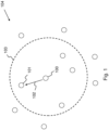
- Fig. 1 gives a schematic representation of a wireless communication network 104, comprising nodes 100 and 101.
- the node 100 is able to communicate with its neighbour nodes 101, located within the range 103 of node 100. Other nodes are out of the range 103 of the node 100, and therefore cannot communicate directly with node 100.
- Every node 100, 101 of the wireless communication network 104 has one or more transceivers that may be working in full-duplex or half-duplex mode.
- Fig. 1 shows a transmission 102 from node 100 to destination node 101.
- the wireless communication network 104 makes use of a time-shared medium.
- the medium may refer to a licensed spectrum, like e.g. the licensed 4G/LTE frequency bands, an unlicensed spectrum, like e.g. Wi-Fi, or a combination of a licensed and unlicensed spectrum.
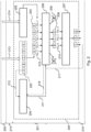
- Medium access of a node 100 to the shared medium is managed by a device 200, which is schematically presented in Fig. 2 .
- every node 100, 101 of the network 104 has its own device 200, such that medium access control is managed in a distributed way.
- the device 200 comprises a slot allocation module 204, a validation module 206 and a scheduling module 207.
- the device 200 is working at the MAC layer 201, and receives information from a higher layer 202, e.g. the Application layer. As shown in Fig. 2 , this information is not received directly from the Application layer 202, but one or more intermediate layers 215 are available between the Application layer 202 and the MAC layer 201.
- the Application layer 202 is followed by the Presentation layer, the Session layer, the Transport layer, the Network layer, the Data Link layer and the Physical layer 216, where the MAC layer 201 is part of the Data Link layer.
- a data flow 213, to be transmitted from node 100 to destination node 101 is received by the device 200, resulting in data packets 203.
- the embodiment of Fig. 2 further shows a cross-layer API 205, configured to obtain QoS requirements 214 from the higher layer 202.
- the QoS requirements 214 comprise a latency requirement 210 for each data packet 203.
- the QoS requirements 214 may comprise additional requirements, like a maximum allowed Packet Error Rate for the data flow 213.
- the slot allocation module 204 is configured to allocate a timeslot 302 for the communication from node 100 to destination node 101.
- the allocation of a timeslot 302 is triggered by the receipt of a first data packet 203 by the device 200, as is indicated with 212 in the figure.
- Information 211 about the allocated timeslot 302, e.g. its position in time, is communicated to the validation module 206.
- the validation module 206 is configured to validate a data packet 203, based on a latency requirement 210 and an expected latency, where the latter is calculated using the timeslot information 211. This validation results in an approved data packet 208 or a disapproved data packet 209. Approved data packets 208 are transmitted to the scheduling module 207, while disapproved data packets 209 are dropped.
- the scheduling module 207 may determine a preferred order of transmission for the approved data packets 208, e.g. in Fig. 2 the packet indicated with 'C' will be transmitted first, although it was not received first by the device 200. After scheduling, the approved data packets 208 are transmitted at the Physical layer 216. If transmission of a data packet 208 is not successful, it is given back to the validation module 206, as is illustrated with 217 in the figure. There, it may be validated again before retransmission. Finally, the validation module 206 may trigger the slot allocation module 204 to allocate an additional timeslot, e.g. if validation shows that many data packets need to be dropped, see 218 in Fig. 2 .
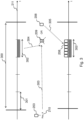
- Fig. 3 shows a timeline 211 and a superframe with duration 300.
- the superframe duration 300 comprises multiple timeslots 301.
- a timeslot 302 has been allocated for a specific communication from node 100 to destination node 101.
- the superframe 300 is executed in a repetitive way, where the communication from node 100 to 101 continues each time the timeslot 302 is on turn.
- the timeslot duration and number of timeslots shown in Fig. 3 are merely schematic and may vary according to various embodiments.
- the TDMA superframe may comprise multiple timeslots 301 as well as multiple frequency channels, where a time-frequency slot needs to be allocated before starting transmission.
- Various embodiments may use different types of protocols for the allocation of a timeslot 302. For example, a static allocation in a TDMA scheme may be used, or dynamic TDMA scheduling where timeslot usage is dynamically repurposed in function of the actual demands and topology of a wireless ad hoc network. Reservation of timeslots 301 may be based on requests and received feedback from the destination node 101 and/or other neighbour nodes. Typically, control messages are exchanged between nodes for making slot allocations. A separate control channel may be provided for the exchange of control messages, or specific control slots may be reserved within the TDMA scheme. Nodes 100 may store the information about free and allocated slots themselves, e.g. by maintaining a table, or may collect this information from other nodes at the time of slot allocation.
- Fig. 3 further shows a data packet 203, with latency requirement 210, e.g. a maximum allowed latency for packet 203.
- Latency requirement information 303 and the position in time 304 of the allocated timeslot 302 are used to validate the data packet 203.
- the timeslot information 304 may include, for example, the start time of the allocated timeslot 302 and its duration. The validation results in a disapproved data packet 209 or an approved data packet 208.
- the scheduling module 207 is configured to sequence the data packets to be transmitted within the timeslot 302. This implies that a specific transmission order is determined, e.g. based on the latency requirements 210 and/or the remaining time until the latency deadline will be exceeded as may be calculated from the timeslot information 304.
- other requirements like a PER requirement may be taken into account for sequencing.
- a disapproved data packet 209 is not scheduled within timeslot 302 and not transmitted. Therefore, no bandwidth is wasted for transmitting useless data packets 209 for which the latency requirement 210 cannot be met.
- disapproved data packets may be handled otherwise. E.g. their actual scheduling and transmission may be postponed until a moment of low data traffic load.
- multiple timeslots 404, 302, within the same superframe 300 may be allocated for a specific transmission from a node 100 to a destination node 101. This is illustrated in Fig. 4a .
- the validation results obtained by the validation module 206 may act as a trigger for allocating one or more additional slots in a TDMA protocol that supports dynamic slot allocation.
- the device may trigger a request for new slots to be allocated to the specific destination. In this way, the link capacity is enlarged and therefore the chance of handling incoming traffic while succeeding the QoS requirements is improved.
- the device acts as an enabler to match spectrum usage to incoming data load.
- a number of data packets 402 will be scheduled within the timeslot 302 of the current superframe 300, while the remaining data packets 403 will be scheduled within the timeslot 401 of the next superframe 400.
- the remaining data packets 403 are validated again by the validation module 206. For example, they may be validated again with regard to their latency requirement 210 at the start of the next superframe 400, or validation may be done at the end of every timeslot. Data packets 403 that were originally approved for scheduling within timeslot 302, but could not be scheduled within the timeslot 302, may be disapproved later on because a transmission within timeslot 401 would lead to a violation of the latency requirement 210.
- a timeslot 302 can be fully or partially filed.
- the device 200 may periodically check during execution of the timeslot 302 whether new packets were received and successfully validated. If that is the case, those newly generated packets may be scheduled as well.
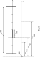
- Fig. 5 illustrates how the validation of a data packet 203 may be done, according to an embodiment of the invention.
- Fig. 5 gives a case where the data packet 210 is approved.
- the timestamp 500 indicates the time of birth of a data packet 210, e.g. the time it was received by the device 200 or created in the Application layer 202.
- the timestamp 501 represents the current time, i.e. 'now'.
- the timeslot 302, with duration 505, a start time 502 and an end time 503, has been allocated for the specific transmission.
- the time duration 508 represents the maximum allowed latency, as given in the latency requirement 210 for the data packet 203. Starting from the time of birth 500, the data packet 203 should arrive at the destination node 101 at the latest at time 509.
- the time duration 507 between time of birth 500 and the current time 501, is the current lifetime of the data packet 203.
- the time duration 504 is the remaining time until start of the timeslot 302.
- Time duration 506, being the addition of time duration 504 and the timeslot duration 505, is the remaining time until end of the timeslot 302.
- the data packet 210 may be transmitted close to the start time 502 of the slot 302.
- the data packet 210 may be transmitted close to the end time 503 of the timeslot 302.
- the time duration 506 may be considered as the remaining time until the packet 203 will reach its destination.
- the expected latency 510 of the data packet 203 may be calculated as the addition of the current lifetime 507 and the remaining time to the destination 506.
- Fig. 5 shows that, for the considered data packet 210, the expected latency 510 is smaller than the maximally allowed latency 508, and therefore the data packet may be approved.
- additional time-based parameters may be taken into account for calculating the remaining time until the packet 203 will reach its destination.
- a processing time within the Physical layer 216 and/or a queueing delay between layers may be taken into account.
- another scenario than the aforementioned worst-case scenario may be considered, e.g. where it is assumed that data packet 203 will be transmitted close to the start time 502 of the timeslot 302, or half-way the timeslot 302. This results in a higher risk that non-useful data packets 203 are transmitted instead of being dropped, because in reality they were sent e.g. close to the end of the timeslot 302.
- the worst-case scenario for validation results in a larger chance of dropping a data packet 203 that would have arrived at time.
- the validation as illustrated in Fig. 5 may be done for each data packet 203 to be transmitted for the first time. In case no successful acknowledgement from the receiver is obtained after a first transmission, the data packet 203 may be retransmitted. In an embodiment, a validation in function of the latency requirement 210 using an approach like described above may be applied before retransmission. If at the current time the expected latency for the retransmitted data packet is still lower than the maximally allowed latency, the data packet is approved for retransmission. Otherwise it may be dropped.
- the number of retransmissions of a specific data packet 203 may be monitored and compared with a maximum allowed number of retransmissions.
- the latter may be statically defined, being the same for every data packet, or may dynamically be calculated.
- the maximum allowed number of retransmissions is calculated as the ratio of 'A' and 'B'.
- 'A' represents the remaining time until the maximum allowed latency is reached, and may be calculated by subtracting the current lifetime 507 and the timeslot duration 505 from the maximally allowed latency 508, see Fig. 5 .
- 'B' represents an average retransmission delay, which may be calculated as a ratio of the superframe duration 300 and the number of timeslots 302 being allocated for the transmission.
- the calculated result may be capped to a predefined maximum. In this way, when many timeslots 302 are allocated for the transmission or the maximum allowed latency is high, the maximally allowed number of retransmissions is high and capped to the predefined maximum. When less timeslots 302 are allocated for the transmission or the maximum allowed latency is low, the maximally allowed number of retransmissions will be lower than the predefined maximum.
- additional QoS requirements 214 may be received by the device 200.
- a reliability requirement in the form of a maximally allowed Packet Error Rate (PER) may be used by the device 200.
- the device 200 may be configured to monitor the actual Packet Error Rate for a specific transmission.
- a PER is the percentage of transmitted packets that is not successfully received by the destination node 101, irrespective whether retransmission(s) were needed or not. It may be monitored e.g. by counting the number of successful acknowledgements by the receiver, or by counting the number of disapproved or dropped data packets by the validation module 206. When many retransmissions are allowed, e.g.
- the monitored PER will be low as not many packets are dropped by the validation module 206. However, in other cases, where the validation module 206 needs to drop many packets, the monitored PER may reach the maximally allowed PER. In such a case various actions may be triggered by the device 200. For example, an additional timeslot 302 may be allocated by the allocation module 206 for that transmission. Accordingly, a dynamically calculated maximum allowed number of retransmissions, as described above, will increase, leading to a decrease in the number of dropped packets. A second action may be to allow for more retransmissions for the specific data flow. A third action may be to adapt parameters at the Physical layer, e.g. reduce the MCS value (Modulation and Coding Scheme) to increase the likelihood of successful transmissions.
- MCS value Modulation and Coding Scheme
- the device 200 may be configured to fragment a data packet, as is illustrated in Fig. 6a .
- the Physical layer responsible for the actual transmission, may impose a maximum size 601 of a transmitted data packet. That maximum size 601 may depend on the actual running mode of the Physical layer, based on the link status or link quality to the destination node. Accordingly, data packets 203 handled by the device 200 at the MAC layer may not be larger than a predefined maximum size 601.
- a parent data packet 600 is received by the device 200, e.g. from the Application layer, the parent data packet 600 is fragmented into data packets 203, which will further be validated and scheduled by the device 200. As is illustrated in Fig.
- the latency requirement 603 as received from the higher layer 202 for the parent data packet 600 is assigned as an individual latency requirement 210 to each of the resulting data packets 203. In this way violation of the latency requirement 603 at the Application level is avoided. Moreover, all of the data packets 203 originating from the same parent data packet 600 may be dropped if validation of one of said data packets 203 results in a disapproved data packet. In this way, a large parent data packet 600 is either dropped or transmitted as a whole.
- Fig. 6b shows that a small data packet 604 may be received from the higher layer 202. As the data packet 604 is smaller than the predefined maximum size 601, no fragmentation is needed, and a small data packet 606 will be validated and scheduled by the device 200. Alternatively, a small data packet 606 may occur as a small remaining part from fragmenting a large parent data packet 601.
- a small data packet 606 may be aggregated with another small data packet during scheduling. This is illustrated in Fig. 7a , where two small data packets 700 and 701 are aggregated to form an aggregated data packet 702, that is scheduled within the allocated timeslot 302.
- a small data packet 700 is not scheduled immediately, but first pushed to a buffer where more packets are waiting to be aggregated. When enough data packets are available in the buffer, an aggregated data packet 702 is formed that is ready to be sent to the destination.
- the size of an aggregated data packet 702 is smaller than but close to a maximum predefined size 601 determined by the Physical layer. As is illustrated in Fig.
- Fig. 7a shows that if a small data packet 703 is not aggregated with other packets, the timeslot 302 cannot be optimally filled, and throughput capacity is lost.
- Pushing a small data packet 700 to an aggregation buffer implies that a delay is introduced before the data packet 700 is effectively scheduled, thereby introducing a risk that the latency constraint 210 of the data packet 700 will be violated.
- a maximum allowed delay before scheduling 801 is calculated, and buffering of a small data packet 700 is only allowed if the maximum allowed delay 801 is larger than a predefined maximum buffer time 800.
- the predefined maximum buffer time 800 controls the maximum time that a packet 700 waits in the aggregation buffer. If this time expires, the packet 700 is scheduled, as a single data packet 700, or as an aggregated data packet already formed but with a maximal size not yet reached.
- the data packet 700 has a maximum allowed latency shown as the time duration 802.
- the data packet 700 needs to be scheduled within timeslot 302 in order to be able to meet the latency requirement; postponing its transmission to a next superframe would lead to a violation of the latency requirement. Therefore, the maximum allowed delay before scheduling 801 is the time between time of birth 400 and the start of the timeslot 302; as soon as execution of the timeslot 302 has started, the data packet 700 cannot be scheduled in time anymore.
- the maximum allowed delay 801 is larger than the predefined buffer time 800. Therefore, buffering a data packet 700, for a time not exceeding the predefined maximum buffer time 800, gives no risk of violating the latency requirement. Consequently, buffering the data packet 700 before scheduling is allowed.
- the data packet 703 has a maximally allowed latency 902, showing that the data packet 703 needs to be scheduled within the timeslot 302.
- the maximum allowed delay before scheduling 901 is smaller than the predefined maximum buffer time 900, buffering of the data packet 703 is not allowed. Consequently, the data packet 703 is scheduled immediately, without waiting for possible aggregation partners first, as is illustrated in Fig. 7b . Scheduling a small data packet 703 without aggregation may occur if buffering is not allowed due to the latency requirement of the packet 703, or if the data packet 703 has been buffered for some time, but the maximum buffer time was exceeded before an aggregation partner was available.
Landscapes
- Engineering & Computer Science (AREA)
- Computer Networks & Wireless Communication (AREA)
- Signal Processing (AREA)
- Quality & Reliability (AREA)
- Multimedia (AREA)
- Mobile Radio Communication Systems (AREA)
Claims (13)
- Vorrichtung (200) zur Medienzugangskontrolle eines Knotens (100) eines drahtlosen Kommunikationsnetzwerks (104) mit zeitgeteiltem Medium, umfassend:- ein Schlitzzuweisungsmodul (204), das dazu konfiguriert ist, einen Zeitschlitz (302) für die Übertragung eines Datenflusses (213) von dem Knoten (100) zu einem Zielknoten (101) über das zeitgeteilte Medium zuzuweisen, wobei der Datenfluss (213) mehrere an den Zielknoten (101) zu übertragende Datenpakete (203) umfasst und der Zeitschlitz (302) ein Zeitintervall innerhalb der Dauer eines Superframes (300) ist, sodass der zugewiesene Zeitschlitz (302) ausschließlich für die dem Datenfluss (213) entsprechende Kommunikation reserviert ist, wodurch ein kollisionsfreier Medienzugang bei wiederholter Ausführung des Superframes (300) gewährleistet wird;- ein Validierungsmodul (206), das dazu konfiguriert ist, ein in dem Datenfluss (213) umfasstes Datenpaket (203) vor der Übertragung an den Zielknoten (101) zu validieren basierend auf∘ einer Latenzanforderung (210) für das Datenpaket (203), wobei die Latenzanforderung (210) eine maximal zulässige Latenz (508) für das Datenpaket (203) ist und durch eine Anwendung definiert wird, die auf der Anwendungsebene (202) arbeitet, und∘ einer erwarteten Latenz (510) für das Datenpaket (203), wobei die erwartete Latenz (510) auf der zeitlichen Position des Zeitschlitzes (302) basiert,was zu einem genehmigten Datenpaket (208) oder einem abgelehnten Datenpaket (209) führt, wobei das Validierungsmodul (206) dazu konfiguriert ist, das Datenpaket (203) durch Vergleichen der erwarteten Latenz (510) mit der maximal zulässigen Latenz (508) zu validieren, was zu einem genehmigten Datenpaket (208) führt, wenn die erwartete Latenz (510) kleiner ist als die maximal zulässige Latenz (508), und andernfalls zu einem abgelehnten Datenpaket (209) führt;- ein Planungsmodul (207), das dazu konfiguriert ist, in dem Zeitschlitz (302) ein in dem Datenfluss (213) umfasstes ist und von dem Validierungsmodul (206) genehmigtes Datenpaket (208) zur Übertragung an den Zielknoten (101) einzuplanen, wobei das genehmigte Datenpaket (208) in dem Zeitschlitz (302) zusammen mit anderen Datenpaketen, die in dem Datenfluss (213) umfasst sind und von dem Validierungsmodul (206) genehmigt wurden, eingeplant ist,und wobei die Vorrichtung (200) dazu konfiguriert ist, ein in dem Datenfluss (213) umfasstes und von dem Validierungsmodul (206) abgelehntes Datenpaket (209) zu verwerfen, sodass das abgelehnte Datenpaket (209) von dem Planungsmodul (207) nicht in dem Zeitschlitz (302) eingeplant wird und nicht an den Zielknoten (101) übertragen wird.
- Vorrichtung (200) nach Anspruch 1,
wobei die Vorrichtung (200) eine Schnittstelle umfasst, die dazu konfiguriert ist, eine oder mehrere Anforderungen (214), die die Latenzanforderung (210) umfassen, von einer Anwendung zu empfangen. - Vorrichtung (200) nach einem der vorhergehenden Ansprüche,
wobei das Validierungsmodul (206) dazu konfiguriert ist, die erwartete Latenz (510) für das Datenpaket (203) basierend auf der aktuellen Lebensdauer (507) des Datenpakets (203) und der aktuell verbleibenden Zeit (504) bis zum Beginn des Zeitschlitzes (302) zu berechnen. - Vorrichtung (200) nach einem der vorhergehenden Ansprüche,
wobei das Validierungsmodul (206) dazu konfiguriert ist, das Datenpaket (203) vor der erneuten Übertragung basierend auf der Anzahl Male, die das Datenpaket (203) übertragen wurde, und einer maximal zulässigen Anzahl erneuter Übertragungen für das Datenpaket (203) zu validieren. - Vorrichtung (200) nach Anspruch 4,
wobei die maximal zulässige Anzahl erneuter Übertragungen für das Datenpaket (203) auf der Anzahl der für die Übertragung von dem Knoten (100) zu dem Zielknoten (101) zugewiesenen Zeitschlitze und/oder der Latenzanforderung (210) basiert. - Vorrichtung nach Anspruch 2,
wobei die Anforderungen (214) eine maximal zulässige Paketfehlerrate umfassen und das Schlitzzuweisungsmodul (204) dazu konfiguriert ist, einen zusätzlichen Zeitschlitz (301) für die Übertragung von dem Knoten (100) zu dem Zielknoten (101) basierend auf der maximal zulässigen Paketfehlerrate und einer überwachten Paketfehlerrate für die Übertragung zuzuweisen. - Vorrichtung nach einem der vorhergehenden Ansprüche,
wobei das Schlitzzuweisungsmodul (204) dazu konfiguriert ist, einen zusätzlichen Zeitschlitz (301) für die Übertragung von dem Knoten (100) an den Zielknoten (101) basierend auf den Ergebnissen des Validierungsmoduls (206) zuzuweisen, wenn mehrere Datenpakete (203) vor der Übertragung an den Zielknoten (101) validiert werden. - Vorrichtung (200) nach einem der vorhergehenden Ansprüche,
wobei das Planungsmodul (207) dazu konfiguriert ist, in dem Datenfluss (213) umfasste und von dem Validierungsmodul (206) genehmigte Datenpakete (208) nach ihren jeweiligen Latenzanforderungen (210) und/oder erwarteten Latenzen (510) zu sequenzieren. - Vorrichtung (200) nach einem der vorhergehenden Ansprüche,wobei das Validierungsmodul (206) dazu konfiguriert ist, die Latenzanforderung (210) und die zeitliche Position des Zeitschlitzes (302) zu verwenden, um eine maximal zulässige Verzögerung (801, 901) zu berechnen, bevor das Datenpaket (203) zur Übertragung eingeplant wird, undwobei das Planungsmodul (207) dazu konfiguriert ist, das Datenpaket (700) vor dem Einplanen zur Übertragung zu puffern, wenn die maximal zulässige Verzögerung (801, 901) größer als eine vordefinierte maximale Pufferzeit (800, 900) ist, und das Datenpaket (700) beim Einplanen zur Übertragung in dem Zeitschlitz (302) mit einem anderen Datenpaket zu vereinigen.
- Vorrichtung (200) nach einem der vorhergehenden Ansprüche,
wobei die Vorrichtung (200) dazu konfiguriert ist, ein übergeordnetes Datenpaket (600) von einer höheren Ebene zu empfangen, das übergeordnete Datenpaket (600) in Datenpakete (203) einer vordefinierten Maximalgröße (601) zu segmentieren, die das Datenpaket (203) umfassen, und jedem der Datenpakete (203), die von dem übergeordneten Datenpaket (600) stammen, dieselbe Latenzanforderung (210) zuzuteilen. - Vorrichtung (200) nach Anspruch 10,
wobei die Vorrichtung (200) dazu konfiguriert ist, alle Datenpakete (203), die von dem übergeordneten Datenpaket (600) stammen, zu verwerfen, wenn die Validierung eines der Datenpakete (203) durch das Validierungsmodul (206) zu einem abgelehnten Datenpaket (209) führt. - Verfahren zur Medienzugangskontrolle eines Knotens (100) eines drahtlosen Kommunikationsnetzwerks (104) mit zeitgeteiltem Medium, umfassend:- Zuweisen eines Zeitschlitzes (302) zur Übertragung eines Datenflusses (213) von dem Knoten (100) zu einem Zielknoten (101) über das zeitgeteilte Medium, wobei der Datenfluss (213) mehrere an den Zielknoten (101) zu übertragende Datenpakete (203) umfasst und der Zeitschlitz (302) ein Zeitintervall innerhalb der Dauer eines Superframes (300) ist, sodass der zugewiesene Zeitschlitz (302) ausschließlich für die dem Datenfluss (213) entsprechende Kommunikation reserviert ist, wodurch ein kollisionsfreier Medienzugang bei wiederholter Ausführung des Superframes (300) gewährleistet wird;- Validieren eines in dem Datenfluss (213) umfassten Datenpakets (203) vor der Übertragung an den Zielknoten (101) basierend auf∘ einer Latenzanforderung (210) für das Datenpaket (203), wobei die Latenzanforderung (210) eine maximal zulässige Latenz (508) für das Datenpaket (203) ist und durch eine Anwendung definiert wird, die auf der Anwendungsebene arbeitet, und∘ einer erwarteten Latenz (510) für das Datenpaket (203), wobei die erwartete Latenz (510) auf der zeitlichen Position des Zeitschlitzes (302) basiert,was zu einem genehmigten Datenpaket (208) oder einem abgelehnten Datenpaket (209) führt, wobei das Datenpaket (203) durch Vergleichen der erwarteten Latenz (510) mit der maximal zulässigen Latenz (508) validiert wird, was zu einem genehmigten Datenpaket (208) führt, wenn die erwartete Latenz (510) kleiner ist als die maximal zulässige Latenz (508), und was andernfalls zu einem abgelehnten Datenpaket (209) führt;- Einplanen, in dem Zeitschlitz (302), eines in dem Datenfluss (213) umfassten Datenpakets (208), das genehmigt ist, zur Übertragung an den Zielknoten (101), wobei das genehmigte Datenpaket (208) zusammen mit anderen in dem Datenfluss (213) umfassten Datenpaketen, die genehmigt sind, in dem Zeitschlitz (302) eingeplant wird;und wobei ein in dem Datenfluss (213) umfasstes Datenpaket (209), das abgelehnt ist, verworfen wird, sodass das abgelehnte Datenpaket (209) nicht in dem Zeitschlitz (302) eingeplant wird und nicht an den Zielknoten (101) übertragen wird.
- Computerprogrammprodukt, umfassend computerausführbare Anweisungen zum Bewirken, dass eine Vorrichtung zumindest Folgendes durchführt:- Zuweisen eines Zeitschlitzes (302) zur Übertragung eines Datenflusses (213) von dem Knoten (100) zu einem Zielknoten (101) über das zeitgeteilte Medium, wobei der Datenfluss (213) mehrere an den Zielknoten (101) zu übertragende Datenpakete (203) umfasst und der Zeitschlitz (302) ein Zeitintervall innerhalb der Dauer eines Superframes (300) ist, sodass der zugewiesene Zeitschlitz (302) ausschließlich für die dem Datenfluss (213) entsprechende Kommunikation reserviert ist, wodurch ein kollisionsfreier Medienzugang bei wiederholter Ausführung des Superframes (300) gewährleistet wird;- Validieren eines in dem Datenfluss (213) umfassten Datenpakets (203) vor der Übertragung an den Zielknoten (101) basierend auf∘ einer Latenzanforderung (210) für das Datenpaket (203), wobei die Latenzanforderung (210) eine maximal zulässige Latenz (508) für das Datenpaket (203) ist und durch eine Anwendung definiert wird, die auf der Anwendungsebene arbeitet, und∘ einer erwarteten Latenz (510) für das Datenpaket (203), wobei die erwartete Latenz (510) auf der zeitlichen Position des Zeitschlitzes (302) basiert,was zu einem genehmigten Datenpaket (208) oder einem abgelehnten Datenpaket (209) führt, wobei das Datenpaket (203) durch Vergleichen der erwarteten Latenz (510) mit der maximal zulässigen Latenz (508) validiert wird, was zu einem genehmigten Datenpaket (208) führt, wenn die erwartete Latenz (510) kleiner ist als die maximal zulässige Latenz (508), und was andernfalls zu einem abgelehnten Datenpaket (209) führt;- Einplanen, in dem Zeitschlitz (302), eines in dem Datenfluss (213) umfassten Datenpakets (208), das genehmigt ist, zur Übertragung an den Zielknoten (101), wobei das genehmigte Datenpaket (208) zusammen mit anderen in dem Datenfluss (213) umfassten Datenpaketen, die genehmigt sind, in dem Zeitschlitz (302) eingeplant wird;und wobei ein in dem Datenfluss (213) umfasstes Datenpaket (209), das abgelehnt ist, verworfen wird, sodass das abgelehnte Datenpaket (209) nicht in dem Zeitschlitz (302) eingeplant wird und nicht an den Zielknoten (101) übertragen wird.
Applications Claiming Priority (2)
| Application Number | Priority Date | Filing Date | Title |
|---|---|---|---|
| EP19195071.6A EP3790203A1 (de) | 2019-09-03 | 2019-09-03 | Vorrichtung und verfahren zur anwendungsbedarfsbewussten medienzugangskontrolle |
| PCT/EP2020/074496 WO2021043841A1 (en) | 2019-09-03 | 2020-09-02 | Device and method for application-requirement aware medium access control |
Publications (2)
| Publication Number | Publication Date |
|---|---|
| EP4026384A1 EP4026384A1 (de) | 2022-07-13 |
| EP4026384B1 true EP4026384B1 (de) | 2025-03-05 |
Family
ID=67875238
Family Applications (2)
| Application Number | Title | Priority Date | Filing Date |
|---|---|---|---|
| EP19195071.6A Withdrawn EP3790203A1 (de) | 2019-09-03 | 2019-09-03 | Vorrichtung und verfahren zur anwendungsbedarfsbewussten medienzugangskontrolle |
| EP20761496.7A Active EP4026384B1 (de) | 2019-09-03 | 2020-09-02 | Vorrichtung und verfahren zur anwendungsbedarfsbewussten medienzugangskontrolle |
Family Applications Before (1)
| Application Number | Title | Priority Date | Filing Date |
|---|---|---|---|
| EP19195071.6A Withdrawn EP3790203A1 (de) | 2019-09-03 | 2019-09-03 | Vorrichtung und verfahren zur anwendungsbedarfsbewussten medienzugangskontrolle |
Country Status (3)
| Country | Link |
|---|---|
| US (1) | US12335773B2 (de) |
| EP (2) | EP3790203A1 (de) |
| WO (1) | WO2021043841A1 (de) |
Families Citing this family (2)
| Publication number | Priority date | Publication date | Assignee | Title |
|---|---|---|---|---|
| DE102022003531A1 (de) * | 2022-09-27 | 2024-03-28 | Mercedes-Benz Group AG | Verfahren und Kommunikations-Steuergerät zur Datenübertragung in einem Fahrzeug |
| CN120321779B (zh) * | 2025-06-17 | 2025-08-12 | 深圳市烽云技术有限公司 | 一种提高无线自组网业务速率的方法和装置 |
Family Cites Families (9)
| Publication number | Priority date | Publication date | Assignee | Title |
|---|---|---|---|---|
| CN103401663B (zh) * | 2006-01-05 | 2017-05-17 | 诺基亚技术有限公司 | 一种用于通信系统的灵活分段方案 |
| US7929546B2 (en) * | 2006-05-25 | 2011-04-19 | Motorola Solutions, Inc. | Systems, methods and apparatus for allocating time slots in an ad hoc wireless communication network |
| US7742495B2 (en) * | 2006-11-20 | 2010-06-22 | Broadcom Corporation | System and method for retransmitting packets over a network of communication channels |
| CN101902817B (zh) * | 2009-05-26 | 2015-07-22 | 中兴通讯股份有限公司 | 无线通信系统中上行无线资源调度方法与装置 |
| WO2011076239A1 (en) | 2009-12-24 | 2011-06-30 | Telecom Italia S.P.A. | A method of scheduling transmission in a communication network, corresponding communication node and computer program product |
| CN103812786B (zh) * | 2012-11-14 | 2017-04-05 | 电信科学技术研究院 | 一种时隙资源的调度方法及装置 |
| US9525641B1 (en) * | 2014-01-24 | 2016-12-20 | Google Inc. | Facilitating buffer wait time determination based on device- or entity-related conditions |
| US9762496B2 (en) * | 2014-02-25 | 2017-09-12 | Qualcomm Incorporated | Slotted message access protocol for powerline communication networks |
| US9319332B2 (en) * | 2014-07-18 | 2016-04-19 | Cisco Technology, Inc. | Distributed rescheduling of bounded flows in a time sensitive network |
-
2019
- 2019-09-03 EP EP19195071.6A patent/EP3790203A1/de not_active Withdrawn
-
2020
- 2020-09-02 US US17/635,959 patent/US12335773B2/en active Active
- 2020-09-02 WO PCT/EP2020/074496 patent/WO2021043841A1/en not_active Ceased
- 2020-09-02 EP EP20761496.7A patent/EP4026384B1/de active Active
Also Published As
| Publication number | Publication date |
|---|---|
| EP3790203A1 (de) | 2021-03-10 |
| EP4026384A1 (de) | 2022-07-13 |
| US20220330082A1 (en) | 2022-10-13 |
| US12335773B2 (en) | 2025-06-17 |
| WO2021043841A1 (en) | 2021-03-11 |
Similar Documents
| Publication | Publication Date | Title |
|---|---|---|
| CN106304377B (zh) | 一种进行调度的方法和设备 | |
| US12069638B2 (en) | Network entity and user equipment for exploiting resilience to consecutive transmission failures | |
| EP2094049B1 (de) | Verfahren und Vorrichtung zum Senden von RLC-PDU in einem Mobilfunkkommunikationssystem | |
| CN113875272B (zh) | 实时应用 | |
| JP2010502056A (ja) | 無線ネットワーク内でアップリンクスケジューリング要求および緊急状態を報告するための方法およびデバイス | |
| US20160338044A1 (en) | Data transmission method and system, and device | |
| CN118891951A (zh) | 用于逻辑信道优先化的设备及方法 | |
| EP1433286A1 (de) | Eine klasse rechnerisch sparsamer scheduler zur durchsetzung von quality-of-service über paketgestützte av-zentrische hausnetzwerke | |
| US12150162B2 (en) | Resource allocation in wireless network | |
| US20090303970A1 (en) | Wireless communication system, base station, scheduling method, and program | |
| US9560670B2 (en) | Method of managing coexisting packet streams | |
| US6963534B1 (en) | Methodology for improving the performance of asynchronous data traffic over TDD/TDMA wireless networks | |
| JP2009060213A (ja) | 無線通信装置、無線通信システム、無線通信方法及びプログラム | |
| EP1553718B1 (de) | Fehlerprüfungsverfahren und System mit Rückkopplung des Ressourcezuteilungsschemas | |
| EP4026384B1 (de) | Vorrichtung und verfahren zur anwendungsbedarfsbewussten medienzugangskontrolle | |
| EP2556714B1 (de) | Verfahren und Knoten zur Handhabung von Warteschlangen in Kommunikationsnetzen und entsprechendes Computerprogrammprodukt | |
| JP4821270B2 (ja) | 許容遅延時間を考慮した無線アクセス制御方法、アクセスポイント、端末及びプログラム | |
| JP2010154420A (ja) | 無線通信装置 | |
| CN100593303C (zh) | 以最低资源参数执行调度算法的方法和调度器 | |
| US20240275522A1 (en) | System and method for dynamic adaption in data transfer in ultra-wideband communication | |
| WO2008012789A1 (en) | Method for reduced latency wireless communication having reduced latency and increased range and handoff performance between different transmitting stations | |
| WO2011038529A1 (zh) | 调度方法和调度器 | |
| CN116233882A (zh) | 用于操作通信网络中的一个或多个节点的方法 | |
| Trsek | Deterministic Medium Access Control | |
| HK1146437A (en) | Methods for scheduling resources in a telecommunication system |
Legal Events
| Date | Code | Title | Description |
|---|---|---|---|
| STAA | Information on the status of an ep patent application or granted ep patent |
Free format text: STATUS: UNKNOWN |
|
| STAA | Information on the status of an ep patent application or granted ep patent |
Free format text: STATUS: THE INTERNATIONAL PUBLICATION HAS BEEN MADE |
|
| PUAI | Public reference made under article 153(3) epc to a published international application that has entered the european phase |
Free format text: ORIGINAL CODE: 0009012 |
|
| STAA | Information on the status of an ep patent application or granted ep patent |
Free format text: STATUS: REQUEST FOR EXAMINATION WAS MADE |
|
| 17P | Request for examination filed |
Effective date: 20220323 |
|
| AK | Designated contracting states |
Kind code of ref document: A1 Designated state(s): AL AT BE BG CH CY CZ DE DK EE ES FI FR GB GR HR HU IE IS IT LI LT LU LV MC MK MT NL NO PL PT RO RS SE SI SK SM TR |
|
| DAV | Request for validation of the european patent (deleted) | ||
| DAX | Request for extension of the european patent (deleted) | ||
| RAP3 | Party data changed (applicant data changed or rights of an application transferred) |
Owner name: UNIVERSITEIT GENT Owner name: IMEC VZW |
|
| REG | Reference to a national code |
Ref country code: DE Ref legal event code: R079 Free format text: PREVIOUS MAIN CLASS: H04W0072120000 Ipc: H04L0001186700 Ref document number: 602020047258 Country of ref document: DE |
|
| GRAP | Despatch of communication of intention to grant a patent |
Free format text: ORIGINAL CODE: EPIDOSNIGR1 |
|
| STAA | Information on the status of an ep patent application or granted ep patent |
Free format text: STATUS: GRANT OF PATENT IS INTENDED |
|
| RIC1 | Information provided on ipc code assigned before grant |
Ipc: H04L 47/32 20220101ALN20241009BHEP Ipc: H04L 47/28 20220101ALN20241009BHEP Ipc: H04L 1/20 20060101ALN20241009BHEP Ipc: H04W 72/543 20230101ALI20241009BHEP Ipc: H04L 1/1867 20230101AFI20241009BHEP |
|
| INTG | Intention to grant announced |
Effective date: 20241021 |
|
| GRAS | Grant fee paid |
Free format text: ORIGINAL CODE: EPIDOSNIGR3 |
|
| GRAA | (expected) grant |
Free format text: ORIGINAL CODE: 0009210 |
|
| STAA | Information on the status of an ep patent application or granted ep patent |
Free format text: STATUS: THE PATENT HAS BEEN GRANTED |
|
| AK | Designated contracting states |
Kind code of ref document: B1 Designated state(s): AL AT BE BG CH CY CZ DE DK EE ES FI FR GB GR HR HU IE IS IT LI LT LU LV MC MK MT NL NO PL PT RO RS SE SI SK SM TR |
|
| REG | Reference to a national code |
Ref country code: GB Ref legal event code: FG4D |
|
| REG | Reference to a national code |
Ref country code: CH Ref legal event code: EP |
|
| REG | Reference to a national code |
Ref country code: IE Ref legal event code: FG4D |
|
| REG | Reference to a national code |
Ref country code: DE Ref legal event code: R096 Ref document number: 602020047258 Country of ref document: DE |
|
| P01 | Opt-out of the competence of the unified patent court (upc) registered |
Free format text: CASE NUMBER: APP_14886/2025 Effective date: 20250327 |
|
| PG25 | Lapsed in a contracting state [announced via postgrant information from national office to epo] |
Ref country code: RS Free format text: LAPSE BECAUSE OF FAILURE TO SUBMIT A TRANSLATION OF THE DESCRIPTION OR TO PAY THE FEE WITHIN THE PRESCRIBED TIME-LIMIT Effective date: 20250605 |
|
| PG25 | Lapsed in a contracting state [announced via postgrant information from national office to epo] |
Ref country code: FI Free format text: LAPSE BECAUSE OF FAILURE TO SUBMIT A TRANSLATION OF THE DESCRIPTION OR TO PAY THE FEE WITHIN THE PRESCRIBED TIME-LIMIT Effective date: 20250305 |
|
| REG | Reference to a national code |
Ref country code: NL Ref legal event code: MP Effective date: 20250305 |
|
| PG25 | Lapsed in a contracting state [announced via postgrant information from national office to epo] |
Ref country code: ES Free format text: LAPSE BECAUSE OF FAILURE TO SUBMIT A TRANSLATION OF THE DESCRIPTION OR TO PAY THE FEE WITHIN THE PRESCRIBED TIME-LIMIT Effective date: 20250305 |
|
| REG | Reference to a national code |
Ref country code: LT Ref legal event code: MG9D |
|
| PG25 | Lapsed in a contracting state [announced via postgrant information from national office to epo] |
Ref country code: NO Free format text: LAPSE BECAUSE OF FAILURE TO SUBMIT A TRANSLATION OF THE DESCRIPTION OR TO PAY THE FEE WITHIN THE PRESCRIBED TIME-LIMIT Effective date: 20250605 |
|
| PG25 | Lapsed in a contracting state [announced via postgrant information from national office to epo] |
Ref country code: HR Free format text: LAPSE BECAUSE OF FAILURE TO SUBMIT A TRANSLATION OF THE DESCRIPTION OR TO PAY THE FEE WITHIN THE PRESCRIBED TIME-LIMIT Effective date: 20250305 |
|
| PG25 | Lapsed in a contracting state [announced via postgrant information from national office to epo] |
Ref country code: LV Free format text: LAPSE BECAUSE OF FAILURE TO SUBMIT A TRANSLATION OF THE DESCRIPTION OR TO PAY THE FEE WITHIN THE PRESCRIBED TIME-LIMIT Effective date: 20250305 |
|
| PG25 | Lapsed in a contracting state [announced via postgrant information from national office to epo] |
Ref country code: BG Free format text: LAPSE BECAUSE OF FAILURE TO SUBMIT A TRANSLATION OF THE DESCRIPTION OR TO PAY THE FEE WITHIN THE PRESCRIBED TIME-LIMIT Effective date: 20250305 Ref country code: GR Free format text: LAPSE BECAUSE OF FAILURE TO SUBMIT A TRANSLATION OF THE DESCRIPTION OR TO PAY THE FEE WITHIN THE PRESCRIBED TIME-LIMIT Effective date: 20250606 |
|
| REG | Reference to a national code |
Ref country code: AT Ref legal event code: MK05 Ref document number: 1773939 Country of ref document: AT Kind code of ref document: T Effective date: 20250305 |
|
| PG25 | Lapsed in a contracting state [announced via postgrant information from national office to epo] |
Ref country code: NL Free format text: LAPSE BECAUSE OF FAILURE TO SUBMIT A TRANSLATION OF THE DESCRIPTION OR TO PAY THE FEE WITHIN THE PRESCRIBED TIME-LIMIT Effective date: 20250305 |
|
| PG25 | Lapsed in a contracting state [announced via postgrant information from national office to epo] |
Ref country code: SE Free format text: LAPSE BECAUSE OF FAILURE TO SUBMIT A TRANSLATION OF THE DESCRIPTION OR TO PAY THE FEE WITHIN THE PRESCRIBED TIME-LIMIT Effective date: 20250305 |
|
| PG25 | Lapsed in a contracting state [announced via postgrant information from national office to epo] |
Ref country code: SM Free format text: LAPSE BECAUSE OF FAILURE TO SUBMIT A TRANSLATION OF THE DESCRIPTION OR TO PAY THE FEE WITHIN THE PRESCRIBED TIME-LIMIT Effective date: 20250305 |
|
| PG25 | Lapsed in a contracting state [announced via postgrant information from national office to epo] |
Ref country code: PT Free format text: LAPSE BECAUSE OF FAILURE TO SUBMIT A TRANSLATION OF THE DESCRIPTION OR TO PAY THE FEE WITHIN THE PRESCRIBED TIME-LIMIT Effective date: 20250707 |
|
| PGFP | Annual fee paid to national office [announced via postgrant information from national office to epo] |
Ref country code: DE Payment date: 20250820 Year of fee payment: 6 |
|
| PG25 | Lapsed in a contracting state [announced via postgrant information from national office to epo] |
Ref country code: PL Free format text: LAPSE BECAUSE OF FAILURE TO SUBMIT A TRANSLATION OF THE DESCRIPTION OR TO PAY THE FEE WITHIN THE PRESCRIBED TIME-LIMIT Effective date: 20250305 Ref country code: IT Free format text: LAPSE BECAUSE OF FAILURE TO SUBMIT A TRANSLATION OF THE DESCRIPTION OR TO PAY THE FEE WITHIN THE PRESCRIBED TIME-LIMIT Effective date: 20250305 |
|
| PGFP | Annual fee paid to national office [announced via postgrant information from national office to epo] |
Ref country code: GB Payment date: 20250820 Year of fee payment: 6 |
|
| PG25 | Lapsed in a contracting state [announced via postgrant information from national office to epo] |
Ref country code: AT Free format text: LAPSE BECAUSE OF FAILURE TO SUBMIT A TRANSLATION OF THE DESCRIPTION OR TO PAY THE FEE WITHIN THE PRESCRIBED TIME-LIMIT Effective date: 20250305 |
|
| PGFP | Annual fee paid to national office [announced via postgrant information from national office to epo] |
Ref country code: FR Payment date: 20250820 Year of fee payment: 6 |
|
| PG25 | Lapsed in a contracting state [announced via postgrant information from national office to epo] |
Ref country code: EE Free format text: LAPSE BECAUSE OF FAILURE TO SUBMIT A TRANSLATION OF THE DESCRIPTION OR TO PAY THE FEE WITHIN THE PRESCRIBED TIME-LIMIT Effective date: 20250305 Ref country code: CZ Free format text: LAPSE BECAUSE OF FAILURE TO SUBMIT A TRANSLATION OF THE DESCRIPTION OR TO PAY THE FEE WITHIN THE PRESCRIBED TIME-LIMIT Effective date: 20250305 |
|
| PG25 | Lapsed in a contracting state [announced via postgrant information from national office to epo] |
Ref country code: RO Free format text: LAPSE BECAUSE OF FAILURE TO SUBMIT A TRANSLATION OF THE DESCRIPTION OR TO PAY THE FEE WITHIN THE PRESCRIBED TIME-LIMIT Effective date: 20250305 |
|
| PG25 | Lapsed in a contracting state [announced via postgrant information from national office to epo] |
Ref country code: SK Free format text: LAPSE BECAUSE OF FAILURE TO SUBMIT A TRANSLATION OF THE DESCRIPTION OR TO PAY THE FEE WITHIN THE PRESCRIBED TIME-LIMIT Effective date: 20250305 |
|
| PG25 | Lapsed in a contracting state [announced via postgrant information from national office to epo] |
Ref country code: IS Free format text: LAPSE BECAUSE OF FAILURE TO SUBMIT A TRANSLATION OF THE DESCRIPTION OR TO PAY THE FEE WITHIN THE PRESCRIBED TIME-LIMIT Effective date: 20250705 |
|
| REG | Reference to a national code |
Ref country code: DE Ref legal event code: R097 Ref document number: 602020047258 Country of ref document: DE |
|
| PLBE | No opposition filed within time limit |
Free format text: ORIGINAL CODE: 0009261 |
|
| STAA | Information on the status of an ep patent application or granted ep patent |
Free format text: STATUS: NO OPPOSITION FILED WITHIN TIME LIMIT |
|
| PG25 | Lapsed in a contracting state [announced via postgrant information from national office to epo] |
Ref country code: DK Free format text: LAPSE BECAUSE OF FAILURE TO SUBMIT A TRANSLATION OF THE DESCRIPTION OR TO PAY THE FEE WITHIN THE PRESCRIBED TIME-LIMIT Effective date: 20250305 |
|
| REG | Reference to a national code |
Ref country code: CH Ref legal event code: L10 Free format text: ST27 STATUS EVENT CODE: U-0-0-L10-L00 (AS PROVIDED BY THE NATIONAL OFFICE) Effective date: 20260114 |
|
| 26N | No opposition filed |
Effective date: 20251208 |