EP4026348B1 - Haut-parleur multivoie directif doté d'un guide d'ondes - Google Patents
Haut-parleur multivoie directif doté d'un guide d'ondes Download PDFInfo
- Publication number
- EP4026348B1 EP4026348B1 EP20860947.9A EP20860947A EP4026348B1 EP 4026348 B1 EP4026348 B1 EP 4026348B1 EP 20860947 A EP20860947 A EP 20860947A EP 4026348 B1 EP4026348 B1 EP 4026348B1
- Authority
- EP
- European Patent Office
- Prior art keywords
- loudspeaker
- resonator
- enclosure
- driver
- accordance
- Prior art date
- Legal status (The legal status is an assumption and is not a legal conclusion. Google has not performed a legal analysis and makes no representation as to the accuracy of the status listed.)
- Active
Links
Images





Classifications
-
- H—ELECTRICITY
- H04—ELECTRIC COMMUNICATION TECHNIQUE
- H04R—LOUDSPEAKERS, MICROPHONES, GRAMOPHONE PICK-UPS OR LIKE ACOUSTIC ELECTROMECHANICAL TRANSDUCERS; ELECTRIC HEARING AIDS; PUBLIC ADDRESS SYSTEMS
- H04R1/00—Details of transducers, loudspeakers or microphones
- H04R1/20—Arrangements for obtaining desired frequency or directional characteristics
- H04R1/22—Arrangements for obtaining desired frequency or directional characteristics for obtaining desired frequency characteristic only
- H04R1/28—Transducer mountings or enclosures modified by provision of mechanical or acoustic impedances, e.g. resonator, damping means
-
- H—ELECTRICITY
- H04—ELECTRIC COMMUNICATION TECHNIQUE
- H04R—LOUDSPEAKERS, MICROPHONES, GRAMOPHONE PICK-UPS OR LIKE ACOUSTIC ELECTROMECHANICAL TRANSDUCERS; ELECTRIC HEARING AIDS; PUBLIC ADDRESS SYSTEMS
- H04R1/00—Details of transducers, loudspeakers or microphones
- H04R1/02—Casings; Cabinets ; Supports therefor; Mountings therein
-
- H—ELECTRICITY
- H04—ELECTRIC COMMUNICATION TECHNIQUE
- H04R—LOUDSPEAKERS, MICROPHONES, GRAMOPHONE PICK-UPS OR LIKE ACOUSTIC ELECTROMECHANICAL TRANSDUCERS; ELECTRIC HEARING AIDS; PUBLIC ADDRESS SYSTEMS
- H04R1/00—Details of transducers, loudspeakers or microphones
- H04R1/20—Arrangements for obtaining desired frequency or directional characteristics
- H04R1/22—Arrangements for obtaining desired frequency or directional characteristics for obtaining desired frequency characteristic only
- H04R1/24—Structural combinations of separate transducers or of two parts of the same transducer and responsive respectively to two or more frequency ranges
-
- H—ELECTRICITY
- H04—ELECTRIC COMMUNICATION TECHNIQUE
- H04R—LOUDSPEAKERS, MICROPHONES, GRAMOPHONE PICK-UPS OR LIKE ACOUSTIC ELECTROMECHANICAL TRANSDUCERS; ELECTRIC HEARING AIDS; PUBLIC ADDRESS SYSTEMS
- H04R1/00—Details of transducers, loudspeakers or microphones
- H04R1/20—Arrangements for obtaining desired frequency or directional characteristics
- H04R1/22—Arrangements for obtaining desired frequency or directional characteristics for obtaining desired frequency characteristic only
- H04R1/26—Spatial arrangements of separate transducers responsive to two or more frequency ranges
-
- H—ELECTRICITY
- H04—ELECTRIC COMMUNICATION TECHNIQUE
- H04R—LOUDSPEAKERS, MICROPHONES, GRAMOPHONE PICK-UPS OR LIKE ACOUSTIC ELECTROMECHANICAL TRANSDUCERS; ELECTRIC HEARING AIDS; PUBLIC ADDRESS SYSTEMS
- H04R1/00—Details of transducers, loudspeakers or microphones
- H04R1/20—Arrangements for obtaining desired frequency or directional characteristics
- H04R1/22—Arrangements for obtaining desired frequency or directional characteristics for obtaining desired frequency characteristic only
- H04R1/28—Transducer mountings or enclosures modified by provision of mechanical or acoustic impedances, e.g. resonator, damping means
- H04R1/2807—Enclosures comprising vibrating or resonating arrangements
- H04R1/2815—Enclosures comprising vibrating or resonating arrangements of the bass reflex type
- H04R1/2819—Enclosures comprising vibrating or resonating arrangements of the bass reflex type for loudspeaker transducers
-
- H—ELECTRICITY
- H04—ELECTRIC COMMUNICATION TECHNIQUE
- H04R—LOUDSPEAKERS, MICROPHONES, GRAMOPHONE PICK-UPS OR LIKE ACOUSTIC ELECTROMECHANICAL TRANSDUCERS; ELECTRIC HEARING AIDS; PUBLIC ADDRESS SYSTEMS
- H04R1/00—Details of transducers, loudspeakers or microphones
- H04R1/20—Arrangements for obtaining desired frequency or directional characteristics
- H04R1/22—Arrangements for obtaining desired frequency or directional characteristics for obtaining desired frequency characteristic only
- H04R1/28—Transducer mountings or enclosures modified by provision of mechanical or acoustic impedances, e.g. resonator, damping means
- H04R1/2807—Enclosures comprising vibrating or resonating arrangements
- H04R1/2838—Enclosures comprising vibrating or resonating arrangements of the bandpass type
- H04R1/2846—Vents, i.e. ports, e.g. shape thereof or tuning thereof with damping material
- H04R1/2849—Vents, i.e. ports, e.g. shape thereof or tuning thereof with damping material for loudspeaker transducers
-
- H—ELECTRICITY
- H04—ELECTRIC COMMUNICATION TECHNIQUE
- H04R—LOUDSPEAKERS, MICROPHONES, GRAMOPHONE PICK-UPS OR LIKE ACOUSTIC ELECTROMECHANICAL TRANSDUCERS; ELECTRIC HEARING AIDS; PUBLIC ADDRESS SYSTEMS
- H04R1/00—Details of transducers, loudspeakers or microphones
- H04R1/20—Arrangements for obtaining desired frequency or directional characteristics
- H04R1/22—Arrangements for obtaining desired frequency or directional characteristics for obtaining desired frequency characteristic only
- H04R1/28—Transducer mountings or enclosures modified by provision of mechanical or acoustic impedances, e.g. resonator, damping means
- H04R1/2869—Reduction of undesired resonances, i.e. standing waves within enclosure, or of undesired vibrations, i.e. of the enclosure itself
- H04R1/2873—Reduction of undesired resonances, i.e. standing waves within enclosure, or of undesired vibrations, i.e. of the enclosure itself for loudspeaker transducers
-
- H—ELECTRICITY
- H04—ELECTRIC COMMUNICATION TECHNIQUE
- H04R—LOUDSPEAKERS, MICROPHONES, GRAMOPHONE PICK-UPS OR LIKE ACOUSTIC ELECTROMECHANICAL TRANSDUCERS; ELECTRIC HEARING AIDS; PUBLIC ADDRESS SYSTEMS
- H04R1/00—Details of transducers, loudspeakers or microphones
- H04R1/20—Arrangements for obtaining desired frequency or directional characteristics
- H04R1/32—Arrangements for obtaining desired frequency or directional characteristics for obtaining desired directional characteristic only
- H04R1/34—Arrangements for obtaining desired frequency or directional characteristics for obtaining desired directional characteristic only by using a single transducer with sound reflecting, diffracting, directing or guiding means
-
- H—ELECTRICITY
- H04—ELECTRIC COMMUNICATION TECHNIQUE
- H04R—LOUDSPEAKERS, MICROPHONES, GRAMOPHONE PICK-UPS OR LIKE ACOUSTIC ELECTROMECHANICAL TRANSDUCERS; ELECTRIC HEARING AIDS; PUBLIC ADDRESS SYSTEMS
- H04R1/00—Details of transducers, loudspeakers or microphones
- H04R1/20—Arrangements for obtaining desired frequency or directional characteristics
- H04R1/32—Arrangements for obtaining desired frequency or directional characteristics for obtaining desired directional characteristic only
- H04R1/34—Arrangements for obtaining desired frequency or directional characteristics for obtaining desired directional characteristic only by using a single transducer with sound reflecting, diffracting, directing or guiding means
- H04R1/345—Arrangements for obtaining desired frequency or directional characteristics for obtaining desired directional characteristic only by using a single transducer with sound reflecting, diffracting, directing or guiding means for loudspeakers
-
- H—ELECTRICITY
- H04—ELECTRIC COMMUNICATION TECHNIQUE
- H04R—LOUDSPEAKERS, MICROPHONES, GRAMOPHONE PICK-UPS OR LIKE ACOUSTIC ELECTROMECHANICAL TRANSDUCERS; ELECTRIC HEARING AIDS; PUBLIC ADDRESS SYSTEMS
- H04R1/00—Details of transducers, loudspeakers or microphones
- H04R1/20—Arrangements for obtaining desired frequency or directional characteristics
- H04R1/22—Arrangements for obtaining desired frequency or directional characteristics for obtaining desired frequency characteristic only
- H04R1/28—Transducer mountings or enclosures modified by provision of mechanical or acoustic impedances, e.g. resonator, damping means
- H04R1/2869—Reduction of undesired resonances, i.e. standing waves within enclosure, or of undesired vibrations, i.e. of the enclosure itself
- H04R1/2876—Reduction of undesired resonances, i.e. standing waves within enclosure, or of undesired vibrations, i.e. of the enclosure itself by means of damping material, e.g. as cladding
- H04R1/288—Reduction of undesired resonances, i.e. standing waves within enclosure, or of undesired vibrations, i.e. of the enclosure itself by means of damping material, e.g. as cladding for loudspeaker transducers
Definitions
- the present invention relates to loudspeakers.
- the present invention relates to loudspeakers equipped with a waveguide.
- the present invention relates to the preamble portion of claim 1.
- loudspeakers with two or more drivers have exhibited problems with sound diffractions created by discontinuities on the front baffle surface (Face) of the loudspeaker.
- the high frequency driver (tweeter) has been the most critical part in this sense.
- the applicant of the present application has created solutions where the surroundings of the tweeter have been formed as a continuous waveguide for high and midrange frequency audio signals either merely for a tweeter and/or midrange driver or alternatively for a coaxial midrange-tweeter driver.
- these kinds of sound sources are referred to as waveguide drivers and they include any drivers located in the centre of this three dimensional waveguide structure.
- good sound quality and accurate directing of the sound energy may be achieved.
- the frequency range and effectiveness of the waveguide for controlling the directivity of radiation depends on the size of the waveguide, determined to a great extent by the surface area covered by the waveguide, and therefore the size of the front baffle (Face) of the loudspeaker.
- Small waveguide area limits directivity control to high frequencies, such as the tweeter range only.
- a large waveguide area enables extending the frequency range of directivity control towards lower frequencies, such as the midrange driver frequency range.
- non-coaxial drivers were positioned such that they are not disturbing the waveguide form created on the front surface (Face) of the enclosure and if positioned on the same surface (the front side (Face) of the enclosure) they are covered with a material that functions advantageously as a solid surface in selected frequencies and restricts penetration of the frequencies emitted by the sound source(s) for which the waveguide has been designed and on the other hand being permeable to other frequencies, more specifically the frequencies radiated by the non-coaxial driver(s), typically woofer(s), emit.
- a spherical loudspeaker is known from DE 19908631 A1 , the front section of which has been recessed to form a waveguide, wherein an external driver pod has been added to the void formed by said recess.
- Covering the low frequency driver may cause some problems with the dynamic performance of the driver because the volume displacement of air by the driver requires sufficient openings to allow flow of air.
- the sub volume in front of the woofer may cause unwanted resonances.
- At least some of the problems described above are solved by acoustically connecting either resistive or reactive resonators, which are separate elements of the cast enclosure, to the sub volume of the woofer such that the total volume of the loudspeaker stays as small as possible.
- resistive or reactive resonators are located at least partially around the coaxial element.
- the aim of the invention is to improve the dynamical performance of the woofer(s).
- loudspeaker according to the invention is characterized by what is stated in characterizing portion of claim 1.
- the loudspeaker includes at least one resonator acoustically connected to the sub volume, the resonator being tuned to at least one of unwanted resonances of the sub volume.
- the low frequency driver may be covered and yet problems with the resonances caused by the sub volume of the woofer may be suppressed.
- the suppression may take place in multiple frequencies by multiple resonators tuned to different frequencies.
- the entire front surface (Face) of the loudspeaker can be formed as a continuous waveguide for mid- and high frequencies without any disturbing resonances on form the sub volume of the bass driver, yet keeping the total volume of the loudspeaker as small as possible.
- the whole audio range from 18 - 20000 Hz may be directed precisely to one "sweet spot" and in addition the rest of the sound energy is divided to the listening room due to the full waveguide form of the loudspeaker such that the loudspeaker enclosure itself does not essentially affect to the frequency response in other directions than the main direction.
- the signal formed into other directions than the "sweet spot" will be reflected from the walls of the listening room in a non controlled manner.
- the invention however provides an enclosure where the sound pressure is optimally distributed to all directions, whereby also the wall reflections sound natural to human ear.
- the resonator is a separate part, it can be processed from different material with different manufacturing procedure than the cast enclosure. This facilitates manufacturing more detailed components like curved or spiral-shaped resonance cavities. In addition this makes it possible to produce different kind of resonators for alternative drivers for the same cast loudspeaker enclosure.
- the material for the resonator may also be selected freely from plastics to wood based materials and even metal can be used.
- prior art loudspeaker 1 which can at least partially be used in connection with the invention includes a coaxial waveguide driver 3 comprising a tweeter 12 and a midrange driver 13 around it.
- the coaxial driver 3 is positioned in the centre of the three dimensional waveguide surface 8, also a front surface (Face) of the enclosure 2.
- the enclosure is typically made of cast metal, advantageously aluminium. Also other castable or moldable materials, such as ⁇ tic combination may be used as a material of the enclosure.
- the waveguide surface 8 radiates the main acoustic power of the driver 3.
- the waveguide 8 has a smooth continuous surface with axially symmetrical features around the centre of the waveguide driver 3.
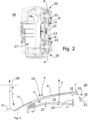
- Two woofer drivers 4 are positioned symmetrically on both sides of the waveguide driver 3 inside the enclosure 2 and narrow ports (openings) 20, first ports are formed just behind the waveguide surface for the woofers 4 in order to let the acoustic energy out from the enclosure 2.
- These first ports 20 are in this embodiment in the narrow front ends of the enclosure 2 and these ports are partially visible from the listening direction. In other words the first port 20 is a U-form slot.
- the function of the resonators 40 is to suppress resonations of the woofer sub volume 22.
- These resonators 40 are positioned partially behind the coaxial driver 3 and each sub volume 22 has two resonators on both sides of the coaxial driver 3.
- the sub volume 22 has width W and height H such that the ratio W/H is around 1.8 and typically in the range of 1.0 - 5.
- the resonators 40 are typically an integral part of the enclosure.
- the resonator 40 is filled with a suppressive material 41 like PES wool, open-cell foam material, fibre glass, mineral wool, felt, or other fiberous or open cell or porous materials, or alternatively of any solid material that is manufactured in the place of the volume such that the material an open cell or fiberous structure where the cell size or the fiber size as in the dimensional area of 1 um (micrometer) to 1 mm (millimeter).
- a suppressive material 41 like PES wool, open-cell foam material, fibre glass, mineral wool, felt, or other fiberous or open cell or porous materials, or alternatively of any solid material that is manufactured in the place of the volume such that the material an open cell or fiberous structure where the cell size or the fiber size as in the dimensional area of 1 um (micrometer) to 1 mm (millimeter).
- the resonators 40 may be also are located at least partially behind the coaxial driver 3.
- the two woofers 4 positioned symmetrically around the coaxial driver form an equivalent large woofer radiating essentially along the same acoustic axis 10 through ports 20 as the waveguide driver 3 even though the woofers have their own acoustic axis 11.
- the loudspeaker 1 includes a first driver 3, which is configured to produce a first frequency band B1 and a corresponding first acoustic axis 10, and a second driver 4, which is configured to produce a second frequency band B2, which is different from the first frequency band B1 but may overlap in a cross-over region, and which second frequency band B2 has a second acoustic axis 11.
- the enclosure 2 encloses said drivers 3, 4 and comprises a three dimensional waveguide 8 positioned on a front surface of the enclosure 2 and around the first driver 3.
- the second acoustic axis 11 of individual woofer drivers are non-coaxial with the first acoustic axis 10, however the resultant axis of the multiple symmetrical woofers working together (equivalent woofer driver) has the same acoustic axis as the coaxial driver, waveguide driver 3. This symmetry is however not required in all embodiments of the invention.
- the axes 10 and 11 may be parallel or non-parallel.
- the woofer 4 is positioned inside the enclosure 2 such that a sub volume 22 is formed in front of the woofer 4 and limited by the woofer 4 itself and side walls 23.
- the resonator 40 is acoustically connected to the sub volume 22.
- a suitable suppressing material 41 may be used inside the resonator 40 in order to further attenuate the unwanted frequencies.
- the side walls 33 of the sub volume (front space) 22 form a spacer between the driver 4 and the enclosure 2 sealing the sub volume 22 from the rest of the inner volume 27 of the enclosure 2.
- the inner volume 27 is limited by the enclosure 2 walls, namely front portion 15, side portions 21 and back portion 25.
- first ports 20 are directed substantially orthogonally in relation to first 10 and second 11 axes, most preferably in the range of 60-120 degrees in relation to these axes.
- first ports 20 are conducted to the back portion 25 of the enclosure 2, e.g. by channels, the difference between the direction of the first ports 20 and the axes 10 and 11 may be even 180 degrees.
- the total area of the first ports 20 is the critical feature, therefore the first ports 20 may be only one single first port 20 for each woofer 4 as presented in the figures or may be formed of multiple first ports 20 like a grid with an area corresponding one single port.
- the first ports 20 should not disturb the three dimensional waveguide surface 8, and therefore they are advantageously positioned on the side portions 21 of the enclosure 2. Of course these first ports 20 may be conducted to the back portion 25 of the enclosure 2 by suitable tubes or channels (not shown). In other words the first ports 20 form air passages to areas outside the three dimensional waveguide 8 of the front portion 15 of the enclosure 2.
- the graph of figure 4 shows frequency response of the sub volume 22 of the woofer 4 (solid line) with one resonance at f 0 and corresponding frequency response of a resonator 40 acoustically connected to the sub volume 22 (dashed line), while the resonator 40 compensates for the unwanted resonance of the sub volume 22.
- Figure 5 shows an alternative embodiment with two resistive resonators 40 with different lengths L for two unwanted frequencies of the sub-volume. Also one or two resistive broad band resonator may be used, advantageously filled with suppressive material. In this case the mechanical dimensions (length, width and depth) of the resonator cavity define the tuning frequency or frequencies of the resonator.
- FIG. 6 shows an alternative embodiment with one reactive Helmholtz resonator 40.
- reactive resonators have high quality factor and they are very effective narrow band resonators.
- these type of resonators can be installed several in one sub volume 22 if there are several sharp unwanted resonances. This type of resonator is also tuned to the unwanted frequency or frequencies f 0 .
- the dimensioning of the Helmholtz resonator is explained in the following: The resonance arises from the effect of the acoustic air mass neck of the resonator 40 and the series resonance circuit created by the acoustic compliance of the air volume of the chamber of the resonator. Close to the resonance frequency, the Helmholtz resonator attenuates the unwanted resonance of sub volume 22.
- the neck-cavity system of the resonator 40 can be derived from the air volume of the cavity of the resonator and the diameter of the neck and its length.
- ⁇ 0 c 2 ⁇ A LV in which f 0 is the resonance frequency, c is the speed of sound, A is the cross-sectional area of the neck, L is the length of the neck, and V is the volume of the chamber.
- Figure 7 shows an alternative embodiment with one reactive panel resonator as a resonator. This embodiment is dimensioned in the following way based on the panel 50 mass per unit and cavity depth d:
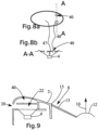
- FIGs 8a shows as a top view a woofer 4 having a planar cover 47 and short tubes 48 forming as well a Helmholtz resonator where the tubes are the necks and the volume between the cover and the woofer cone forms the volume of the resonator.
- this solution is presented as a A-A cross section.
- the tuning principle is the same as in figures 5 and 6 .
- Figure 9 shows another alternative solution, where the resonator 40 is formed between the frontal baffle portion and 15 and the sub volume 22 of the woofer.
- the resonator may be either resistive type without any neck portion or reactive type if the opening to the sub volume 22 is made as a tube.
- the tuning principle is the same as in previous figures.
- the loudspeaker in accordance with the invention functions in accordance with well-known bass reflex principle, where the low frequency driver 4 is tuned in resonance with help of the compliance of the air volume contained inside the enclosure 27 and the air volume contained inside the reflex port 34 of figure 2 .
- the loudspeaker 1 comprises an enclosure 2 defining an inner volume 27 and including a frontal baffle portion 15 (front portion), which has a front port 5 for providing a fluid passageway between the inner volume 27 and the ambient volume 26 of the enclosure 2 and a side portion 21 extending rearward from the periphery of the baffle portion 15.
- the side portion 21 forms side walls or the enclosure 2.
- the enclosure further includes a back portion 25, which is typically essentially parallel with the frontal baffle portion 15 and forming the back side of the enclosure 2.
- the loudspeaker 1 further comprises a driver 4 attached to the enclosure 2, such that the driver 4 is arranged at a distance from the baffle portion 15, forming a sub volume 22 inside the enclosure 2 such that a sub volume 22 is formed between the driver 4 and the baffle portion 15 by a spacer 33, wherein said front port 5 acts as a front port between the sub volume 22 and the ambient volume 28 of the enclosure 2.
- a first port 20 is formed to the enclosure 2 either in the side portion 21 or back portion 25 in order to connect the sub volume 22 and the ambient volume 26 with each other.
- two woofer drivers 4 are positioned on both sides of the waveguide driver 3 inside the enclosure 2 and suitable ports (openings) 5 are formed for the woofers 4 in order to let the acoustic energy out from the enclosure 2.
- the openings 5 are covered with an acoustically transparent layer 6 forming part of the waveguide surface 8. If needed the acoustically transparent layer 6 may be supported from below with support bars 7.
- the woofer driver 4 is typically spaced from the acoustically transparent layer 6.
- the two woofers 4 form an equivalent large woofer radiating essentially along the same acoustic axis 10 as the waveguide driver 3 even though the woofers have their own acoustic axis 11.
- the loudspeaker 1 includes a first driver 3, which is configured to produce a first frequency band B1 and a corresponding first acoustic axis 10, and a second driver 4, which is configured to produce a second frequency band B2, which is different from the first frequency band B1 but may overlap in a cross-over region, and which second frequency band B2 has a second acoustic axis 11.
- the enclosure 2 encloses said drivers 3, 4 and comprises a three dimensional waveguide 8 positioned on a front surface of the enclosure 2 and around the first driver 3.
- the three dimensional waveguide 8 comprises an acoustically selectively transparent portion 6 which is acoustically essentially reflecting to sound waves of the first frequency band B1 propagating in a direction angled to the first acoustic axis 10, the waveguide portion 6 is essentially transparent to sound waves of the second frequency band B2 propagating in the direction of the second acoustic axis through the waveguide portion 6, and the second driver 4 is positioned inside the enclosure 2 behind the acoustically selectively transparent portion 6.
- the second acoustic axis 11 of individual woofer drivers are non-coaxial with the first acoustic axis 10, however the resultant axis of the multiple woofers working together (equivalent woofer driver) has the same acoustic axis as the coaxial driver, waveguide driver 3. This symmetry is however not required in all embodiments of the invention.
- the axes 10 and 11 may be parallel or non-parallel.
- the woofer 4 is positioned inside the enclosure 2 such that a sub volume 22 is formed in front of the woofer 4 and limited by the woofer 4 itself, side walls 23 and the acoustically selectively transparent layer 6.
- a resonator 40 which is tuned to unwanted frequencies created by the sub volume 22.
- the resonator 40 may be either resistive or reactive. With resistive resonator the suppressive characteristics are of broad band type.
- the notch around the center frequency f 0 created by resistive resonator is not so sharp like in the reactive resonators.
- the side walls 33 of the sub volume (front space) 22 form a spacer between the driver 4 and the enclosure 2 sealing the sub volume 22 from the rest of the inner volume 27 of the enclosure 2.
- the inner volume 27 is limited by the enclosure 2 walls, namely front portion 15, side portions 21 and back portion 25.
- the acoustically selectively transparent layer 6 may be replaced by a mechanically protective grid, the grid limiting in this case the sub volume, as well as the inner volume 27.
- the first ports 20 are formed in the side walls 23 of the sub volume 22 and to the side portions 21 of the enclosure 2 in order to optimize the operation of the woofer 4. Without these first ports 20 the performance of the woofer 4 may be compromised.
- the first ports 20 may be positioned on any of the side portions 21, e.g. on the short side portions 21 as shown in the figures or alternatively to the long side portions 21.
- first ports 20 are directed substantially orthogonally in relation to first 10 and second 11 axes, most preferably in the range of 60-120 degrees in relation to these axes.
- first ports 20 are conducted to the back portion 25 of the enclosure 2, e.g. by channels, the difference between the direction of the first ports 20 and the axes 10 and 11 may be even 180 degrees.
- the area of these first ports 20 is typically 5-50 % of the area of the openings 5 for the woofer 4, most advantageously in the range of 10-20% of the area of the openings 5 for the woofer 4.
- the total area of the first ports 20 is the critical feature, therefore the first ports 20 may be only one single first port 20 for each woofer 4 as presented in the figures or may be formed of multiple first ports 20 like a grid with an area corresponding one single port.
- the first ports 20 should not disturb the three dimensional waveguide surface 8, and therefore they are advantageously positioned on the side portions 21 of the enclosure 2. Of course these first ports 20 may be conducted to the back portion 25 of the enclosure 2 by suitable tubes or channels (not shown). In other words the first ports 20 form air passages to areas outside the three dimensional waveguide 8 of the front portion 15 of the enclosure 2.
- the second driver 4 is positioned inside the enclosure 2 behind the acoustically selectively transparent portion 6 and spaced from it, such that a sub volume 22 is formed inside the enclosure 2 and separated from the inner volume 27 by the driver 4 and side walls 23 formed as a spacer between the driver 4 and the front portion 15 of the enclosure 2.
- essentially reflecting means reflection or absorption of at least 50-100 % of the acoustic energy, preferably in the range of 80-100 %.
- essentially transparent means transparency of at least 50-100% of the acoustic energy preferably in the range of 80-100 %.
- the thickness of the layer 6 is advantageously:
- the layer 6 should attenuate the acoustical radiation of the waveguide driver 3, meaning typically in frequencies above 600Hz.
- the layer 6 should have an acoustical impedance (or absorption) as a function of frequency therefore functioning as an acoustical filter in the following way:
- the layer 6 is formed of holes or pores or their combination in the following way:
- the properties for the ideal material for layer 6 are the following:
- the layer 6 may cover the loudspeaker front (tweeter 12 excluded) or only the holes 5.
- the layer 6 may be also formed as a metal structure, like mesh or grid with on one or several layers in accordance with the above requirements for porosity and frequency properties.
- This kind of structure could be formed e.g. by a stack of perforated metal sheets or plates of thickness around 0.2-2 mm. The properties of this kind of stack could be adjusted by placement (distribution) of the holes or pores, percentage (openness) of the holes or pores, and the spacing of the plates from each other.
- the hole or aperture diameter may vary typically around 0.3 -3 mm.
- the spacing between the sheets or plates is typically around 0.2-2 mm.
- a metal structure described above is advantageous, because its propertied can be adjusted freely and the external properties like colour can be as well selected without limitations.
- the crossover frequency C is typically the following:
- the selectively transparent portion 6 may be replaced by a mechanically protective grid not having complete properties of selective transparency.
- the resonator may be divided into multiple independent sub resonators 40', each having its own resonance frequency.
- Figure 13 shows the typical positioning of the loudspeakers 1 in accordance with the invention, where the loudspeakers are directed to the listening position, sweet spot 9. Due to the fact that the complete front surface of the enclosure 2 is formed as a waveguide 8, a very good directivity is achieved. Additionally the waveguide form 8 causes a uniform distribution of all frequencies to all directions in the listening room and therefore the reflections from the walls, ceiling and floor cause no coloration of the sound. Figure 13 indicates also the front portion 15, side portions 21 and back portion 25 of the loudspeaker 1 enclosure 2.
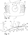
- figure 14 is presented a loudspeaker in which suppressive material 41 is positioned in the resonator cavity 40. Only the upper cavities 40 in the figure are filled with the material but in reality both upper and lower cavities 40 will be filled with suppressive material.
- the resonator unit 51 is typically made of plastic. Other materials like moldable wood or metal can also be used.
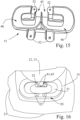
- Figure 15 shows the side of the resonator 51 which will be attached to the front plate 15 of the cast enclosure. The attachment is made typically by screws from the attachment lugs 52.
- the resonator unit is typically conical such that the highest part of the unit is in the center close to the resonator openings 45 and the edges of the unit 51 are correspondingly low. Because the resonator unit 51 is separate from the large cast metal enclosure also detailed structures can be made. In this case the resonator cavity is made strongly curved in order to obtain the desired length L for the resonator cavity in as small total dimension for the resonator unit 51 as possible.
- Figure 16 shows the resonator unit 51connected to the cast metal enclosure, especially to the front portion 15 of the enclosure such that the resonator openings 45 are directed to the coaxial driver including tweeter 12 and midrange driver 13. So the openings 45 of the resonator unit 51 are directed away from the first port 20 of the loudspeaker.
- suppressive material 41 positioned in the cavities and extending to the openings 45 of the cavities.
- FIGS 17 an 18 show to embodiments of the resonator units as dashed lines. Only one resonator unit 51 for each loudspeaker is presented but of course, also a second resonator unit is located in the bottom part of each loudspeaker.
- the uniform loudspeaker enclosure 2 is made by casting or moulding of metal, plastic or wood based material.
Landscapes
- Health & Medical Sciences (AREA)
- Otolaryngology (AREA)
- Physics & Mathematics (AREA)
- Engineering & Computer Science (AREA)
- Acoustics & Sound (AREA)
- Signal Processing (AREA)
- Obtaining Desirable Characteristics In Audible-Bandwidth Transducers (AREA)
- Details Of Audible-Bandwidth Transducers (AREA)
- Audible-Bandwidth Dynamoelectric Transducers Other Than Pickups (AREA)
- Circuit For Audible Band Transducer (AREA)
Claims (14)
- Haut-parleur (1) incluant- une enceinte uniforme (2) présentant une partie avant (15), des parties latérales (21) et une partie arrière (25) définissant un volume intérieur (27),- la partie avant (15) est formée comme une surface guide d'ondes (8) et inclut au moins un moteur (12, 13) dans la surface guide d'ondes (8) et est apte à rayonner la puissance acoustique principale du haut-parleur (1) dans la direction du premier axe acoustique (10), et- au moins un moteur supplémentaire (4) fixé à l'enceinte (2),- le moteur supplémentaire (4) est fixé à l'intérieur de l'enceinte (2) de telle sorte qu'un sous-volume (22) soit formé à l'intérieur du volume interne (27), le sous-volume (22) étant limité par le moteur (4), des éléments de cloisonnement (33) entre le moteur (4) et la partie avant (15), et la partie avant (15) de l'enceinte (2),- au moins un premier orifice (20) est conçu pour s'ouvrir du sous-volume (22) au volume ambiant (26) soit vers la partie latérale (21), soit vers la partie arrière (25) de l'enceinte (2), et
au moins un résonateur (40) incluant au moins une cavité (46) de résonateur reliée acoustiquement au sous-volume (22), le résonateur (40) étant réglé sur au moins l'une de résonances indésirables du sous-volume (22), caractérisé en ce que- le résonateur (40) est formé comme une unité séparée (51) reliée à l'enceinte uniforme (2), et en ce que- l'unité de résonateur (51) est reliée à la surface intérieure de la partie avant (15) de l'enceinte (2). - Haut-parleur selon la revendication 1, caractérisé en ce que l'unité de résonateur (51) est en plastique, matériau à base de bois ou métal.
- Haut-parleur selon la revendication 1 ou 2, caractérisé en ce que l'unité de résonateur (51) comprend une ou plusieurs cavités incurvées (46) avec des ouvertures (45).
- Haut-parleur selon une quelconque revendication précédente, caractérisé en ce que le résonateur (40) est un résonateur résistif présentant des caractéristiques à large bande.
- Haut-parleur selon une quelconque revendication précédente, caractérisé en ce que le résonateur (40) inclut un matériau atténuant (41) tel que de la laine PES, un matériau en mousse à cellules ouvertes, de la fibre de verre, de la laine minérale, du feutre ou d'autres matériaux fibreux ou à cellules ouvertes ou poreux, ou alternativement de tout matériau solide qui est fabriqué à la place du volume de telle sorte que le matériau présente une une structure à cellules ouvertes ou fibreuse où la taille de cellules ou la taille de fibres est comprise dans la zone dimensionnelle de 1 µm (micromètre) à 1 mm (millimètre).
- Haut-parleur selon une quelconque revendication précédente, caractérisé en ce que le résonateur (40) est un résonateur réactif du type résonateur à panneau ou résonateur de Helmholtz.
- Haut-parleur (1) selon une quelconque revendication précédente, caractérisé en ce qu'un second axe acoustique (11) n'est pas coaxial avec le premier axe acoustique (10).
- Haut-parleur (1) selon une quelconque revendication précédente, caractérisé en ce qu'un second axe acoustique (11) n'est pas parallèle au premier axe acoustique (10).
- Haut-parleur (1) selon une quelconque revendication précédente, caractérisé en ce que le premier moteur (3) inclut deux moteurs (12, 13) coaxiaux l'un par rapport à l'autre.
- Haut-parleur (1) selon une quelconque revendication précédente, caractérisé en ce que le premier moteur (3) inclut un seul moteur (12, 13).
- Haut-parleur (1) selon une quelconque revendication précédente, caractérisé en ce que le haut-parleur (1) est un haut-parleur bass-reflex.
- Haut-parleur (1) selon une quelconque revendication précédente, caractérisé en ce que l'enceinte uniforme (2) est réalisée par coulée ou moulage de métal, de plastique ou d'un matériau à base de bois.
- Haut-parleur (1) selon une quelconque revendication précédente, caractérisé en ce que l'enceinte uniforme (2) est réalisée par usinage de métal, de plastique ou d'un matériau à base de bois.
- Haut-parleur (1) selon une quelconque revendication précédente, caractérisé en ce que le au moins un moteur (12, 13) est au centre de la surface guide d'ondes (8).
Applications Claiming Priority (2)
| Application Number | Priority Date | Filing Date | Title |
|---|---|---|---|
| FI20195727 | 2019-09-03 | ||
| PCT/FI2020/050543 WO2021044078A2 (fr) | 2019-09-03 | 2020-08-20 | Haut-parleur multivoie directif doté d'un guide d'ondes |
Publications (3)
| Publication Number | Publication Date |
|---|---|
| EP4026348A2 EP4026348A2 (fr) | 2022-07-13 |
| EP4026348A4 EP4026348A4 (fr) | 2022-10-19 |
| EP4026348B1 true EP4026348B1 (fr) | 2024-10-23 |
Family
ID=74853454
Family Applications (1)
| Application Number | Title | Priority Date | Filing Date |
|---|---|---|---|
| EP20860947.9A Active EP4026348B1 (fr) | 2019-09-03 | 2020-08-20 | Haut-parleur multivoie directif doté d'un guide d'ondes |
Country Status (9)
| Country | Link |
|---|---|
| US (1) | US12200434B2 (fr) |
| EP (1) | EP4026348B1 (fr) |
| JP (1) | JP7531580B2 (fr) |
| KR (1) | KR102604029B1 (fr) |
| CN (1) | CN114430913B (fr) |
| AU (1) | AU2020343462B2 (fr) |
| ES (1) | ES2997357T3 (fr) |
| FI (1) | FI4026348T3 (fr) |
| WO (1) | WO2021044078A2 (fr) |
Families Citing this family (5)
| Publication number | Priority date | Publication date | Assignee | Title |
|---|---|---|---|---|
| US11640816B1 (en) * | 2022-02-23 | 2023-05-02 | Acoustic Metamaterials LLC | Metamaterial acoustic impedance matching device for headphone-type devices |
| US20240080594A1 (en) * | 2022-07-06 | 2024-03-07 | Sound United, LLC | Speakers |
| USD1083876S1 (en) | 2022-07-06 | 2025-07-15 | Sound United, LLC | Audio speaker |
| USD1083877S1 (en) | 2022-07-06 | 2025-07-15 | Sound United, LLC | Audio speaker |
| USD1081622S1 (en) | 2023-07-10 | 2025-07-01 | Sound United, LLC | Audio speaker |
Family Cites Families (37)
| Publication number | Priority date | Publication date | Assignee | Title |
|---|---|---|---|---|
| US2880817A (en) * | 1953-10-28 | 1959-04-07 | Pickard & Burns Inc | Loudspeaker system |
| CH528197A (de) * | 1971-12-20 | 1972-09-15 | Ibm | Gehäuseanordnung mit einem elektro-akustischen Wandler, und Verwendung derselben in einem Telefonapparat einer Nachrichtenübertragungsanlage mit PCM-Codierung |
| US4314620A (en) * | 1980-06-02 | 1982-02-09 | Gollehon Industries, Inc. | Loudspeaker with cone driven horn |
| US4334593A (en) * | 1980-11-18 | 1982-06-15 | Sechrist Edward L | Sound reproduction system |
| US4565905A (en) * | 1982-04-28 | 1986-01-21 | International Jensen Incoporated | Loudspeaker construction |
| US4554414A (en) * | 1983-04-28 | 1985-11-19 | Harman International Industries Incorporated | Multi-driver loudspeaker |
| NL8902831A (nl) * | 1989-11-16 | 1991-06-17 | Philips Nv | Luidsprekersysteem bevattende een helmholtz resonator gekoppeld met een akoestische buis. |
| DE659030T1 (de) * | 1993-12-16 | 1996-01-04 | Toshiba Kawasaki Kk | Lautsprechersystem für Fernsehgeräte. |
| GB2302231B (en) * | 1995-03-14 | 1999-01-13 | Matsushita Electric Industrial Co Ltd | Speaker system |
| JP3560726B2 (ja) * | 1996-04-11 | 2004-09-02 | スター精密株式会社 | 小型電気音響変換器 |
| DK174546B1 (da) * | 1998-12-21 | 2003-05-19 | Sony Ericsson Mobile Comm Ab | Et kommunikationsapparat |
| DE19908631C2 (de) * | 1999-02-27 | 2001-10-31 | Juergen Quaas | Anordnung von Lautsprechern zu Beschallungszwecken |
| US20020014369A1 (en) * | 2000-07-31 | 2002-02-07 | Mark Engebretson | System for integrating mid-range and high frequency acoustic sources in multi-way loudspeakers |
| US6766027B2 (en) * | 2002-08-29 | 2004-07-20 | Dana Innovations | Elliptical flushmount speaker |
| JP2005006053A (ja) | 2003-06-12 | 2005-01-06 | Tadashi Masuda | 低音用スピーカー装置及び該低音用スピーカー装置を備えたマルチウェイスピーカー装置 |
| US8098867B2 (en) * | 2006-11-30 | 2012-01-17 | Motorola Mobility, Inc. | Attachable external acoustic chamber for a mobile device |
| US8351629B2 (en) * | 2008-02-21 | 2013-01-08 | Robert Preston Parker | Waveguide electroacoustical transducing |
| CN201341229Y (zh) * | 2008-12-08 | 2009-11-04 | 王立本 | 一种高效率全音域扬声器 |
| US8483420B2 (en) * | 2010-12-07 | 2013-07-09 | Samsung Electronics Co., Ltd. | Docking station having structure for sound amplification and sound quality enhancement |
| KR101805433B1 (ko) * | 2010-12-07 | 2017-12-08 | 삼성전자 주식회사 | 음량 증대 및 음질 개선을 위한 구조를 갖는 도킹 스테이션 |
| US9107003B2 (en) * | 2011-12-15 | 2015-08-11 | Apple Inc. | Extended duct with damping for improved speaker performance |
| US9033099B2 (en) * | 2012-12-19 | 2015-05-19 | Otter Products, Llc | Protective enclosure for enhancing sound from an electronic device |
| TWI554119B (zh) * | 2013-01-09 | 2016-10-11 | 群邁通訊股份有限公司 | 內置揚聲器組、外接式音箱及電子裝置 |
| FI127222B (en) * | 2013-06-14 | 2018-01-31 | Genelec Oy | Speaker with waveguide |
| US9894433B2 (en) * | 2014-06-16 | 2018-02-13 | PK Event Services Inc. | Audio wave guide |
| JP6619426B2 (ja) * | 2014-10-06 | 2019-12-11 | ゲネレク オーワイ | 導波路を有するラウドスピーカー |
| CN205160785U (zh) * | 2015-11-04 | 2016-04-13 | 北京吴慎天顺科技有限公司 | 高效率低频扬声器 |
| CN206272841U (zh) * | 2016-12-16 | 2017-06-20 | 杭州谱声电子有限公司 | 音乐理疗仪用音箱的谐振腔结构 |
| JP7184369B2 (ja) * | 2017-04-21 | 2022-12-06 | ジェネレック・オーワイ | 導波管を備える指向性マルチウェイスピーカ |
| CN207070330U (zh) * | 2017-06-26 | 2018-03-02 | 歌尔科技有限公司 | 扬声器模组以及电子设备 |
| US10299032B2 (en) * | 2017-09-11 | 2019-05-21 | Apple Inc. | Front port resonator for a speaker assembly |
| US10397693B1 (en) * | 2018-03-09 | 2019-08-27 | Apple Inc. | Acoustic chambers damped with plural resonant chambers, and related systems and methods |
| US11265645B2 (en) * | 2018-09-24 | 2022-03-01 | Apple Inc. | Acoustic chambers damped with side-branch resonators, and related systems and methods |
| US10694281B1 (en) * | 2018-11-30 | 2020-06-23 | Bose Corporation | Coaxial waveguide |
| EP3672279B1 (fr) * | 2018-12-19 | 2023-06-07 | Sonova AG | Dispositif d'aide auditive avec commande de rétroaction active |
| CN109874067A (zh) | 2018-12-30 | 2019-06-11 | 瑞声科技(新加坡)有限公司 | 扬声器箱 |
| US11564032B2 (en) * | 2021-04-30 | 2023-01-24 | Harman International Industries, Incorporated | Speaker system with asymmetrical coverage horn |
-
2020
- 2020-08-20 FI FIEP20860947.9T patent/FI4026348T3/fi active
- 2020-08-20 KR KR1020227011025A patent/KR102604029B1/ko active Active
- 2020-08-20 JP JP2022514592A patent/JP7531580B2/ja active Active
- 2020-08-20 EP EP20860947.9A patent/EP4026348B1/fr active Active
- 2020-08-20 US US17/635,717 patent/US12200434B2/en active Active
- 2020-08-20 CN CN202080061919.5A patent/CN114430913B/zh active Active
- 2020-08-20 WO PCT/FI2020/050543 patent/WO2021044078A2/fr not_active Ceased
- 2020-08-20 AU AU2020343462A patent/AU2020343462B2/en active Active
- 2020-08-20 ES ES20860947T patent/ES2997357T3/es active Active
Also Published As
| Publication number | Publication date |
|---|---|
| EP4026348A4 (fr) | 2022-10-19 |
| ES2997357T3 (en) | 2025-02-17 |
| KR102604029B1 (ko) | 2023-11-20 |
| KR20220054874A (ko) | 2022-05-03 |
| EP4026348A2 (fr) | 2022-07-13 |
| AU2020343462A1 (en) | 2022-03-24 |
| CN114430913A (zh) | 2022-05-03 |
| JP7531580B2 (ja) | 2024-08-09 |
| FI4026348T3 (fi) | 2024-12-20 |
| WO2021044078A3 (fr) | 2021-04-08 |
| US12200434B2 (en) | 2025-01-14 |
| WO2021044078A2 (fr) | 2021-03-11 |
| CN114430913B (zh) | 2025-02-07 |
| JP2022546832A (ja) | 2022-11-09 |
| AU2020343462B2 (en) | 2023-07-13 |
| US20220337941A1 (en) | 2022-10-20 |
Similar Documents
| Publication | Publication Date | Title |
|---|---|---|
| EP3613218B1 (fr) | Haut-parleur multivoie directif doté d'un guide d'ondes | |
| EP4026348B1 (fr) | Haut-parleur multivoie directif doté d'un guide d'ondes | |
| EP3205113B1 (fr) | Haut-parleur comprenant un guide d'ondes | |
| EP2814262B1 (fr) | Haut-parleur équipé d'un guide d'ondes | |
| RU2797532C1 (ru) | Направленная многоканальная акустическая система с волноводом |
Legal Events
| Date | Code | Title | Description |
|---|---|---|---|
| STAA | Information on the status of an ep patent application or granted ep patent |
Free format text: STATUS: THE INTERNATIONAL PUBLICATION HAS BEEN MADE |
|
| PUAI | Public reference made under article 153(3) epc to a published international application that has entered the european phase |
Free format text: ORIGINAL CODE: 0009012 |
|
| STAA | Information on the status of an ep patent application or granted ep patent |
Free format text: STATUS: REQUEST FOR EXAMINATION WAS MADE |
|
| 17P | Request for examination filed |
Effective date: 20220301 |
|
| AK | Designated contracting states |
Kind code of ref document: A2 Designated state(s): AL AT BE BG CH CY CZ DE DK EE ES FI FR GB GR HR HU IE IS IT LI LT LU LV MC MK MT NL NO PL PT RO RS SE SI SK SM TR |
|
| A4 | Supplementary search report drawn up and despatched |
Effective date: 20220919 |
|
| RIC1 | Information provided on ipc code assigned before grant |
Ipc: H04R 1/34 20060101ALI20220913BHEP Ipc: H04R 1/26 20060101ALI20220913BHEP Ipc: H04R 1/24 20060101ALI20220913BHEP Ipc: H04R 1/02 20060101ALI20220913BHEP Ipc: H04R 1/28 20060101AFI20220913BHEP |
|
| DAV | Request for validation of the european patent (deleted) | ||
| DAX | Request for extension of the european patent (deleted) | ||
| GRAP | Despatch of communication of intention to grant a patent |
Free format text: ORIGINAL CODE: EPIDOSNIGR1 |
|
| STAA | Information on the status of an ep patent application or granted ep patent |
Free format text: STATUS: GRANT OF PATENT IS INTENDED |
|
| INTG | Intention to grant announced |
Effective date: 20240612 |
|
| GRAS | Grant fee paid |
Free format text: ORIGINAL CODE: EPIDOSNIGR3 |
|
| GRAA | (expected) grant |
Free format text: ORIGINAL CODE: 0009210 |
|
| STAA | Information on the status of an ep patent application or granted ep patent |
Free format text: STATUS: THE PATENT HAS BEEN GRANTED |
|
| AK | Designated contracting states |
Kind code of ref document: B1 Designated state(s): AL AT BE BG CH CY CZ DE DK EE ES FI FR GB GR HR HU IE IS IT LI LT LU LV MC MK MT NL NO PL PT RO RS SE SI SK SM TR |
|
| REG | Reference to a national code |
Ref country code: GB Ref legal event code: FG4D |
|
| REG | Reference to a national code |
Ref country code: CH Ref legal event code: EP |
|
| REG | Reference to a national code |
Ref country code: DE Ref legal event code: R096 Ref document number: 602020040068 Country of ref document: DE |
|
| REG | Reference to a national code |
Ref country code: IE Ref legal event code: FG4D |
|
| REG | Reference to a national code |
Ref country code: FI Ref legal event code: FGE |
|
| REG | Reference to a national code |
Ref country code: ES Ref legal event code: FG2A Ref document number: 2997357 Country of ref document: ES Kind code of ref document: T3 Effective date: 20250217 |
|
| REG | Reference to a national code |
Ref country code: LT Ref legal event code: MG9D |
|
| REG | Reference to a national code |
Ref country code: NL Ref legal event code: MP Effective date: 20241023 |
|
| REG | Reference to a national code |
Ref country code: AT Ref legal event code: MK05 Ref document number: 1735827 Country of ref document: AT Kind code of ref document: T Effective date: 20241023 |
|
| PG25 | Lapsed in a contracting state [announced via postgrant information from national office to epo] |
Ref country code: NL Free format text: LAPSE BECAUSE OF FAILURE TO SUBMIT A TRANSLATION OF THE DESCRIPTION OR TO PAY THE FEE WITHIN THE PRESCRIBED TIME-LIMIT Effective date: 20241023 |
|
| PG25 | Lapsed in a contracting state [announced via postgrant information from national office to epo] |
Ref country code: NL Free format text: LAPSE BECAUSE OF FAILURE TO SUBMIT A TRANSLATION OF THE DESCRIPTION OR TO PAY THE FEE WITHIN THE PRESCRIBED TIME-LIMIT Effective date: 20241023 |
|
| PG25 | Lapsed in a contracting state [announced via postgrant information from national office to epo] |
Ref country code: PT Free format text: LAPSE BECAUSE OF FAILURE TO SUBMIT A TRANSLATION OF THE DESCRIPTION OR TO PAY THE FEE WITHIN THE PRESCRIBED TIME-LIMIT Effective date: 20250224 Ref country code: IS Free format text: LAPSE BECAUSE OF FAILURE TO SUBMIT A TRANSLATION OF THE DESCRIPTION OR TO PAY THE FEE WITHIN THE PRESCRIBED TIME-LIMIT Effective date: 20250223 Ref country code: HR Free format text: LAPSE BECAUSE OF FAILURE TO SUBMIT A TRANSLATION OF THE DESCRIPTION OR TO PAY THE FEE WITHIN THE PRESCRIBED TIME-LIMIT Effective date: 20241023 |
|
| PG25 | Lapsed in a contracting state [announced via postgrant information from national office to epo] |
Ref country code: BG Free format text: LAPSE BECAUSE OF FAILURE TO SUBMIT A TRANSLATION OF THE DESCRIPTION OR TO PAY THE FEE WITHIN THE PRESCRIBED TIME-LIMIT Effective date: 20241023 |
|
| PG25 | Lapsed in a contracting state [announced via postgrant information from national office to epo] |
Ref country code: NO Free format text: LAPSE BECAUSE OF FAILURE TO SUBMIT A TRANSLATION OF THE DESCRIPTION OR TO PAY THE FEE WITHIN THE PRESCRIBED TIME-LIMIT Effective date: 20250123 |
|
| PG25 | Lapsed in a contracting state [announced via postgrant information from national office to epo] |
Ref country code: LV Free format text: LAPSE BECAUSE OF FAILURE TO SUBMIT A TRANSLATION OF THE DESCRIPTION OR TO PAY THE FEE WITHIN THE PRESCRIBED TIME-LIMIT Effective date: 20241023 Ref country code: AT Free format text: LAPSE BECAUSE OF FAILURE TO SUBMIT A TRANSLATION OF THE DESCRIPTION OR TO PAY THE FEE WITHIN THE PRESCRIBED TIME-LIMIT Effective date: 20241023 Ref country code: GR Free format text: LAPSE BECAUSE OF FAILURE TO SUBMIT A TRANSLATION OF THE DESCRIPTION OR TO PAY THE FEE WITHIN THE PRESCRIBED TIME-LIMIT Effective date: 20250124 |
|
| PG25 | Lapsed in a contracting state [announced via postgrant information from national office to epo] |
Ref country code: PL Free format text: LAPSE BECAUSE OF FAILURE TO SUBMIT A TRANSLATION OF THE DESCRIPTION OR TO PAY THE FEE WITHIN THE PRESCRIBED TIME-LIMIT Effective date: 20241023 |
|
| PG25 | Lapsed in a contracting state [announced via postgrant information from national office to epo] |
Ref country code: RS Free format text: LAPSE BECAUSE OF FAILURE TO SUBMIT A TRANSLATION OF THE DESCRIPTION OR TO PAY THE FEE WITHIN THE PRESCRIBED TIME-LIMIT Effective date: 20250123 |
|
| PG25 | Lapsed in a contracting state [announced via postgrant information from national office to epo] |
Ref country code: SM Free format text: LAPSE BECAUSE OF FAILURE TO SUBMIT A TRANSLATION OF THE DESCRIPTION OR TO PAY THE FEE WITHIN THE PRESCRIBED TIME-LIMIT Effective date: 20241023 |
|
| PG25 | Lapsed in a contracting state [announced via postgrant information from national office to epo] |
Ref country code: DK Free format text: LAPSE BECAUSE OF FAILURE TO SUBMIT A TRANSLATION OF THE DESCRIPTION OR TO PAY THE FEE WITHIN THE PRESCRIBED TIME-LIMIT Effective date: 20241023 |
|
| PG25 | Lapsed in a contracting state [announced via postgrant information from national office to epo] |
Ref country code: EE Free format text: LAPSE BECAUSE OF FAILURE TO SUBMIT A TRANSLATION OF THE DESCRIPTION OR TO PAY THE FEE WITHIN THE PRESCRIBED TIME-LIMIT Effective date: 20241023 |
|
| PG25 | Lapsed in a contracting state [announced via postgrant information from national office to epo] |
Ref country code: RO Free format text: LAPSE BECAUSE OF FAILURE TO SUBMIT A TRANSLATION OF THE DESCRIPTION OR TO PAY THE FEE WITHIN THE PRESCRIBED TIME-LIMIT Effective date: 20241023 |
|
| REG | Reference to a national code |
Ref country code: DE Ref legal event code: R097 Ref document number: 602020040068 Country of ref document: DE |
|
| PG25 | Lapsed in a contracting state [announced via postgrant information from national office to epo] |
Ref country code: SK Free format text: LAPSE BECAUSE OF FAILURE TO SUBMIT A TRANSLATION OF THE DESCRIPTION OR TO PAY THE FEE WITHIN THE PRESCRIBED TIME-LIMIT Effective date: 20241023 |
|
| PG25 | Lapsed in a contracting state [announced via postgrant information from national office to epo] |
Ref country code: CZ Free format text: LAPSE BECAUSE OF FAILURE TO SUBMIT A TRANSLATION OF THE DESCRIPTION OR TO PAY THE FEE WITHIN THE PRESCRIBED TIME-LIMIT Effective date: 20241023 |
|
| PLBE | No opposition filed within time limit |
Free format text: ORIGINAL CODE: 0009261 |
|
| STAA | Information on the status of an ep patent application or granted ep patent |
Free format text: STATUS: NO OPPOSITION FILED WITHIN TIME LIMIT |
|
| PG25 | Lapsed in a contracting state [announced via postgrant information from national office to epo] |
Ref country code: SE Free format text: LAPSE BECAUSE OF FAILURE TO SUBMIT A TRANSLATION OF THE DESCRIPTION OR TO PAY THE FEE WITHIN THE PRESCRIBED TIME-LIMIT Effective date: 20241023 |
|
| 26N | No opposition filed |
Effective date: 20250724 |
|
| PGFP | Annual fee paid to national office [announced via postgrant information from national office to epo] |
Ref country code: FI Payment date: 20250804 Year of fee payment: 6 Ref country code: ES Payment date: 20250926 Year of fee payment: 6 |
|
| PGFP | Annual fee paid to national office [announced via postgrant information from national office to epo] |
Ref country code: DE Payment date: 20250820 Year of fee payment: 6 |
|
| PGFP | Annual fee paid to national office [announced via postgrant information from national office to epo] |
Ref country code: IT Payment date: 20250825 Year of fee payment: 6 |
|
| PGFP | Annual fee paid to national office [announced via postgrant information from national office to epo] |
Ref country code: GB Payment date: 20250820 Year of fee payment: 6 |
|
| PGFP | Annual fee paid to national office [announced via postgrant information from national office to epo] |
Ref country code: FR Payment date: 20250828 Year of fee payment: 6 |
|
| REG | Reference to a national code |
Ref country code: CH Ref legal event code: H13 Free format text: ST27 STATUS EVENT CODE: U-0-0-H10-H13 (AS PROVIDED BY THE NATIONAL OFFICE) Effective date: 20260324 |
|
| PG25 | Lapsed in a contracting state [announced via postgrant information from national office to epo] |
Ref country code: MC Free format text: LAPSE BECAUSE OF FAILURE TO SUBMIT A TRANSLATION OF THE DESCRIPTION OR TO PAY THE FEE WITHIN THE PRESCRIBED TIME-LIMIT Effective date: 20241023 |
|
| PG25 | Lapsed in a contracting state [announced via postgrant information from national office to epo] |
Ref country code: LU Free format text: LAPSE BECAUSE OF NON-PAYMENT OF DUE FEES Effective date: 20250820 |
|
| PG25 | Lapsed in a contracting state [announced via postgrant information from national office to epo] |
Ref country code: CH Free format text: LAPSE BECAUSE OF NON-PAYMENT OF DUE FEES Effective date: 20250831 |