EP4024813A1 - Communications device - Google Patents
Communications device Download PDFInfo
- Publication number
- EP4024813A1 EP4024813A1 EP20859396.2A EP20859396A EP4024813A1 EP 4024813 A1 EP4024813 A1 EP 4024813A1 EP 20859396 A EP20859396 A EP 20859396A EP 4024813 A1 EP4024813 A1 EP 4024813A1
- Authority
- EP
- European Patent Office
- Prior art keywords
- communication device
- data
- transmission request
- drivers
- transmission
- Prior art date
- Legal status (The legal status is an assumption and is not a legal conclusion. Google has not performed a legal analysis and makes no representation as to the accuracy of the status listed.)
- Granted
Links
Images


Classifications
-
- H—ELECTRICITY
- H04—ELECTRIC COMMUNICATION TECHNIQUE
- H04L—TRANSMISSION OF DIGITAL INFORMATION, e.g. TELEGRAPHIC COMMUNICATION
- H04L47/00—Traffic control in data switching networks
- H04L47/10—Flow control; Congestion control
- H04L47/30—Flow control; Congestion control in combination with information about buffer occupancy at either end or at transit nodes
-
- H—ELECTRICITY
- H04—ELECTRIC COMMUNICATION TECHNIQUE
- H04L—TRANSMISSION OF DIGITAL INFORMATION, e.g. TELEGRAPHIC COMMUNICATION
- H04L47/00—Traffic control in data switching networks
- H04L47/10—Flow control; Congestion control
- H04L47/19—Flow control; Congestion control at layers above the network layer
- H04L47/196—Integration of transport layer protocols, e.g. TCP and UDP
-
- H—ELECTRICITY
- H04—ELECTRIC COMMUNICATION TECHNIQUE
- H04L—TRANSMISSION OF DIGITAL INFORMATION, e.g. TELEGRAPHIC COMMUNICATION
- H04L67/00—Network arrangements or protocols for supporting network services or applications
- H04L67/01—Protocols
- H04L67/12—Protocols specially adapted for proprietary or special-purpose networking environments, e.g. medical networks, sensor networks, networks in vehicles or remote metering networks
-
- H—ELECTRICITY
- H04—ELECTRIC COMMUNICATION TECHNIQUE
- H04L—TRANSMISSION OF DIGITAL INFORMATION, e.g. TELEGRAPHIC COMMUNICATION
- H04L69/00—Network arrangements, protocols or services independent of the application payload and not provided for in the other groups of this subclass
- H04L69/16—Implementation or adaptation of Internet protocol [IP], of transmission control protocol [TCP] or of user datagram protocol [UDP]
-
- H—ELECTRICITY
- H04—ELECTRIC COMMUNICATION TECHNIQUE
- H04L—TRANSMISSION OF DIGITAL INFORMATION, e.g. TELEGRAPHIC COMMUNICATION
- H04L69/00—Network arrangements, protocols or services independent of the application payload and not provided for in the other groups of this subclass
- H04L69/16—Implementation or adaptation of Internet protocol [IP], of transmission control protocol [TCP] or of user datagram protocol [UDP]
- H04L69/164—Adaptation or special uses of UDP protocol
Definitions
- the present disclosure relates to a communication device that receives data by using a connectionless protocol.
- Occurrence of an overflow decreases communication efficiency, and thus occurrence of an overflow is suppressed to increase communication efficiency.
- a communication device of a first aspect is a communication device that receives, using a connectionless protocol, data transmitted by a transmission terminal.
- the communication device determines, in accordance with a receivable size of the communication device, a data transmission request for receiving data from the transmission terminal.
- a communication device of a second aspect is the communication device of the first aspect, in which the connectionless protocol is a user datagram protocol (UDP).
- the connectionless protocol is a user datagram protocol (UDP).
- a communication device of a third aspect is the communication device of the first aspect or the second aspect, in which the determining of the data transmission request includes determining of one or more items of the data and/or determining of an interval of the data transmission request to the transmission terminal. In a case where the receivable size is smaller than or equal to a threshold value, the communication device reduces the number of items of the data and/or increases the interval of the data transmission request to the transmission terminal.
- a communication device of a fourth aspect is the communication device of any of the first aspect to the third aspect, in which the communication device calculates the receivable size on the basis of a size of currently free capacity of a reception buffer and a size of currently unreceived data.
- a communication device of a fifth aspect is the communication device of the first aspect or the second aspect, in which the communication device holds a plurality of drivers that at least execute a process of receiving the data.
- the communication device determines the data transmission request on the basis of the number of free drivers that are not executing the process of receiving the data among the plurality of drivers.
- a communication device of a sixth aspect is the communication device of the fifth aspect, in which, in a case where the number of the free drivers is zero, the communication device determines the data transmission request so as not to receive the data. The communication device confirms again the number of the free drivers after a predetermined time elapses. This suppresses occurrence of an overflow in the drivers and contributes to efficient communication between the communication device and the transmission terminal.
- a communication device of a seventh aspect is the communication device of the fifth aspect or the sixth aspect, in which the communication device further sets an upper limit of the number of the drivers that execute the data transmission request.
- a communication device of an eighth aspect is the communication device of any of the first aspect to the seventh aspect, in which the data transmission request is determined on the basis of a degree of priority of an item of the data and/or an interval of the data transmission request of the transmission terminal.
- a communication device of a ninth aspect is the communication device of any of the first aspect to the eighth aspect, in which the communication device has a function of transmitting the received data to another device via a network.
- the communication device determines the data transmission request to the transmission terminal in accordance with a size of free capacity of a transmission buffer.
- a connectionless protocol such as a user datagram protocol (UDP) has been used.
- UDP user datagram protocol
- a communication device first transmits a transmission request to a plurality of transmission terminals connected to the network. Subsequently, each transmission terminal that has received the data transmission request autonomously transmits data to the communication device as a requester.
- a transmission method in which a communication device transmits a transmission request to a plurality of transmission terminals is one-to-one communication or one-to-many communication of transmitting a data transmission request to every transmission terminal connected to the network, or special one-to-many communication of transmitting a data transmission request only to a selected transmission terminal.
- the communication device may simultaneously receive a large amount of data from the plurality of transmission terminals, and an overflow may occur in a reception buffer that temporarily stores the received data.
- a communication device is a store-and-forward communication device, which has been the mainstream in recent years, and receives data larger than a receivable size of the reception buffer of the communication device, the data is discarded and completely lost.
- the invention of the present disclosure described below provides a communication device that prevents such data loss and that suppresses an overflow of a reception buffer or the like so that the communication device efficiently communicates with a plurality of transmission terminals.
- the communication system 100 of a first embodiment illustrated in Fig. 1 includes a single communication device 20 and a plurality of (herein, four) transmission terminals 10. For convenience of description, it is assumed that the plurality of transmission terminals 10 are substantially the same.
- the communication device 20 and each of the plurality of transmission terminals 10 are connected to each other via a network.
- the communication device 20 and each of the transmission terminals 10 are connected to each other via a wired network, but the manner of connection is not limited thereto. Communication between the communication device 20 and each of the transmission terminals 10 is performed by using a connectionless protocol.
- the connectionless protocol is, for example, a UDP.
- Each transmission terminal 10 is, for example, a device such as an air conditioner.
- An air conditioner as the transmission terminal 10 collects, for example, various data such as operation data about the air conditioner, data of an environment around the air conditioner, and input data input by a user or the like.
- the transmission terminal 10 transmits the collected various data to the communication device 20 on the basis of a data transmission request from the communication device 20.
- the transmission terminal 10 includes a central processing unit (CPU), a memory, various interfaces, various sensors, and so forth, which are not illustrated.
- CPU central processing unit
- memory various interfaces, various sensors, and so forth, which are not illustrated.
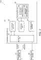
- Fig. 2 illustrates a schematic configuration of the communication device 20.
- the communication device 20 includes a network interface (IF) unit 21 that provides an interface for a network, a reception buffer 22 that temporarily stores data received from the individual transmission terminals 10, a transmission buffer 23 that temporarily stores data to be transmitted to the individual transmission terminals 10, a storage unit 24 that stores a data transmission/reception program and so forth, and a processing unit 25 for implementing functions of a program stored in the storage unit 24.
- IF network interface
- reception buffer 22 and the transmission buffer 23 may be application buffers of an application included in the communication device 20.
- the storage unit 24 includes a read only memory (ROM), a random access memory (RAM), and an external storage device, which are not illustrated.
- the storage unit 24 stores information, a database, or the like required for implementing functions of a program. Specifically, the storage unit 24 stores information about individual data transmission requests, data sizes of pieces of data to be received on the basis of the individual data transmission requests, a threshold value of a receivable size of the reception buffer, and so forth.
- the receivable size of the reception buffer is calculated by a buffer size calculation processing unit 26, which will be described below.
- the threshold value of the receivable size is a value determined by a manager or the like of the communication system 100 at his/her discretion.
- the processing unit 25 includes a CPU, which is not illustrated, and controls the entire communication device 20.
- the processing unit 25 includes the buffer size calculation processing unit 26 and a request determining unit 27.
- the buffer size calculation processing unit 26 monitors the reception buffer 22 and performs a process of calculating a receivable size of the reception buffer 22.
- the receivable size of the reception buffer 22 is the size of data receivable by the reception buffer 22.
- the buffer size calculation processing unit 26 is calculated by using, for example, a difference between a total memory size of the reception buffer 22, and data sizes of individual pieces of data that are currently stored in the reception buffer 22 and data sizes of individual pieces of data that are currently unreceived and are to be received on the basis of transmitted data transmission requests.
- the data size of data to be transmitted by each transmission terminal 10 on the basis of a data transmission request is stored in the storage unit 24 in advance.
- the request determining unit 27 performs determination regarding a data transmission request to be transmitted to the transmission terminals 10, on the basis of the receivable size calculated by the buffer size calculation processing unit 26. For example, in a case where the receivable size of the reception buffer is smaller than or equal to the threshold value, the request determining unit 27 determines to increase a transmission interval of a data transmission request to be transmitted to the transmission terminals 10.
- step ST1 connections are established in the communication system 100 so that communication can be performed as illustrated in Fig. 1 , and the communication device 20 and the individual transmission terminals 10 are started up.
- step ST2 the buffer size calculation processing unit 26 of the communication device 20 calculates a receivable size of the reception buffer 22.
- the request determining unit 27 determines, in step ST3, to transmit a data transmission request to the transmission terminals 10.
- the request determining unit 27 determines, in step ST4, to increase the transmission interval of a data transmission request to be transmitted to the transmission terminals 10. Accordingly, for example, determination is performed to transmit a data transmission request to the transmission terminals 10 after a predetermined period elapses.
- step ST5 the data transmission request determined by the request determining unit 27 is transmitted to the individual transmission terminals 10 via the network IF unit 21.
- Each transmission terminal 10 that has received the data transmission request transmits various data to the communication device 20 on the basis of the data transmission request.
- step ST6 the communication device 20 receives the various data via the network IF unit 21.
- the data that has been received is stored as received data in the reception buffer 22.
- step ST2 to step ST6 are executed at a predetermined time interval or executed on the basis of a request from a manager or the like of the communication system 100.
- the communication device 20 of the first embodiment is the communication device 20 that receives, using a connectionless protocol, data transmitted by the transmission terminal 10.
- the connectionless protocol is, for example, a UDP.
- the communication device 20 determines, in accordance with a receivable size of the communication device 20, a data transmission request for receiving data from the transmission terminal 10.
- the determining of the data transmission request includes determining of an interval of the data transmission request to the transmission terminal. In a case where the receivable size is smaller than or equal to a threshold value, the communication device increases the interval of the data transmission request to the transmission terminal 10.
- the communication device 20 calculates the receivable size on the basis of a size of currently free capacity of the reception buffer 22 and a size of currently unreceived data.
- the communication device 20 of a store-and-forward type temporarily stores received data in the reception buffer 22.
- the data may be discarded and completely lost.
- it is necessary to adjust the data transmission request to be transmitted to each transmission terminal 10 so that data is received within the range of not exceeding the receivable size.
- the communication device 20 illustrated in the first embodiment determines, in accordance with the receivable size of the communication device 20, a data transmission request for receiving data from the transmission terminal 10. Thus, received data does not exceed the receivable size. Accordingly, an overflow of the reception buffer 22 can be suppressed and efficient communication can be performed.
- the communication device 20 illustrated in the first embodiment determines, in accordance with the receivable size of the communication device 20, a data transmission request for receiving data from the transmission terminal 10.
- the data transmission request determined by the communication device 20 may include determination of one or more items of data.
- the items of data are items of information included in the data transmitted by the transmission terminal 10 on the basis of the data transmission request. For example, in a case where the receivable size is larger than or equal to the threshold value, the communication device 20 transmits, to the transmission terminal 10, a data transmission request requesting data about operation data, environment data, and input data of an air conditioning device as the transmission terminal 10.
- the communication device 20 transmits, to the transmission terminal 10, a data transmission request requesting only data about operation data of the air conditioning device. In other words, in a case where the receivable size is smaller than or equal to the threshold value, the communication device 20 reduces the number of items of data.
- a data transmission request to be transmitted to the transmission terminal 10 in a case where the receivable size is larger than or equal to the threshold value, and a data transmission request to be transmitted to the transmission terminal 10 in a case where the receivable size is smaller than or equal to the threshold value may be stored in advance in the storage unit 24 of the communication device 20.
- each item of data may have a degree of priority set thereto.
- the communication device 20 transmits items of data to the transmission terminal 10 in order from the item having the highest priority such that the size of received data does not exceed the receivable size.
- the size of data to be received is reduced, so that the received data does not exceed the receivable size.
- the communication device 20 illustrated in the first embodiment may be connected to a device other than the transmission terminals 10 (management device 30) via the network, as illustrated in Fig. 1 .
- the communication device 20 has a function of transmitting received data to the management device 30 via the network.
- the network herein may be wired or wireless.
- Communication between the communication device 20 and the management device 30 may be communication using a protocol other than a connectionless protocol.
- the communication device 20 has a program of converting received data. Conversion of received data may be performed by the processing unit 25 illustrated in Fig. 2 .
- Transmission data to be transmitted to the management device 30 is temporarily stored in the transmission buffer 23.
- the transmission data is substantially the same as the data received from the transmission terminal 10, but is referred to as transmission data herein for convenience.
- the transmission data may be data obtained by processing data received from the transmission terminal 10 by the processing unit 25.
- the buffer size calculation processing unit 26 of the communication device 20 may calculate a size of free capacity of the transmission buffer 23.
- the size of free capacity of the transmission buffer 23 can be calculated by using a difference between a total memory size of the transmission buffer 23 and the data size of the transmission data currently stored in the transmission buffer 23.
- the total memory size of the transmission buffer 23 and the data size of the transmission data to be transmitted to each transmission terminal 10 may be stored in the storage unit 24.
- the communication device 20 may determine a data transmission request to the transmission terminal 10 in accordance with the size of free capacity of the transmission buffer 23 in addition to the receivable size of the reception buffer 22.
- an overflow of the transmission buffer 23 of the communication device 20 can be suppressed, and efficient communication can be performed.
- a communication system 200 of a second embodiment includes elements that are substantially the same as those of the communication system 100 of the first embodiment.
- the elements of the communication system 200 are denoted by reference numerals in the 200s as illustrated in Fig. 4 .
- the communication system 200 of the second embodiment illustrated in Fig. 4 includes a single communication device 220, a plurality of (herein, four) transmission terminals 210, and a management device 230.
- the communication device 220 and each of the plurality of transmission terminals 210 are connected to each other via a network.
- the communication device 220 and each of the transmission terminals 210 are connected to each other via a wired network, but the manner of connection is not limited thereto.
- Communication between the communication device 220 and each of the transmission terminals 210 is performed by using a connectionless protocol.
- the connectionless protocol is, for example, a UDP.
- the transmission terminals 210 and the management device 230 of the second embodiment have substantially the same configurations as those of the transmission terminals 10 and the management device 30 of the first embodiment, and thus the description thereof is omitted.
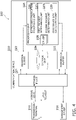
- Fig. 4 illustrates a schematic configuration of the communication device 220.
- the communication device 220 includes a network IF unit 221 that provides an interface for a network, a reception buffer 222 that temporarily stores data received from the individual transmission terminals 210, a transmission buffer 223 that temporarily stores data to be transmitted to the individual transmission terminals 210, a storage unit 224 that stores data received from the individual transmission terminals 210 a data transmission/reception program and so forth, and a processing unit 225 for implementing functions of a program stored in the storage unit 224.
- the storage unit 224 includes a ROM, a RAM, and an external storage device, which are not illustrated, and stores, like the storage unit of the first embodiment, information, a database, or the like required for implementing functions of a program.
- the storage unit 224 also stores, for example, information such as an upper limit value of the number of drivers that execute a data transmission request among a plurality of drivers included in the processing unit 225.
- the processing unit 225 includes a CPU, which is not illustrated, and controls the entire communication device 220.
- the processing unit 225 includes a buffer size calculation processing unit 226 and a first request determining unit 227a (the request determining unit 27 in the first embodiment), and also includes a plurality of drivers 228, a free driver calculation processing unit 229, and a second request determining unit 227b.
- the drivers 228 at least execute a data transmission request determined by the first request determining unit 227a and/or the second request determining unit 227b and execute a process of receiving data transmitted from the individual transmission terminals 210 to the communication device 220 on the basis of the data transmission request.
- the driver 228 that is executing a process of receiving data is referred to as an executing driver
- a driver that is not executing a process of receiving data is referred to as a free driver.
- drivers 228 the number of which exceeds the upper limit value of the number of drivers 228 executing the data transmission request (executing drivers) stored in the storage unit 224 are incapable of simultaneously executing a process.
- the free driver calculation processing unit 229 monitors the drivers 228 and performs a process of calculating the number of free drivers at a predetermined timing set in advance. When the calculated number of free drivers is zero, the free driver calculation processing unit 229 performs again a process of calculating the number of free drivers after a predetermined time set in advance elapses.
- the second request determining unit 227b performs determination regarding a data transmission request to be transmitted to the transmission terminals 210, on the basis of the number of free drivers calculated by the driver calculation processing unit 229. For example, in a case where the number of free drivers is smaller than the upper limit value of the number of executing drivers stored in the storage unit 224, the second request determining unit 227b determines to cause one or a plurality of free drivers to execute a data transmission request. On the other hand, in a case where the number of free drivers is zero (none), the request determining unit 27 determines not to transmit a data transmission request so as not to receive data.
- the communication device 220 illustrated in the second embodiment may perform, at the same time as the communication process, the communication process of the communication device 20 illustrated in the first embodiment.
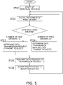
- step ST21 the transmission terminals 210 and the communication device 220 are started up in a state of being connected so as to be capable of communicating with each other.
- step ST22 the free driver calculation processing unit 229 of the communication device 220 calculates the number of free drivers.
- the second request determining unit 227b determines, in step ST23, to cause one or a plurality of free drivers to execute a data transmission request.
- the data transmission request determined at this time is determined on the basis of a degree of priority of an item of data and/or an interval of the data transmission request of the transmission terminal like the data transmission request in the communication system 100 of the first embodiment.
- the second request determining unit 227b determines, in step ST24, not to transmit a data transmission request so as not to receive data.
- the free driver calculation processing unit 229 calculates again the number of free drivers after a predetermined time elapses, and the second request determining unit 227b determines to cause a free driver to execute a data transmission request, as in step ST22 and step ST23.
- step ST5 the data transmission request determined by the second request determining unit 227b is transmitted to each transmission terminal 210 via the network IF unit 221.
- Each transmission terminal 210 that has received the data transmission request transmits various data to the communication device 220 on the basis of the data transmission request.
- step ST26 the communication device 220 receives the various data via the network IF unit 221.
- the data that has been received is stored as received data in the reception buffer 222.
- the received data can be, for example, transmitted to the management device (another device) 230.
- the communication device 220 determines a data transmission request to the transmission terminals 210 in accordance with a size of free capacity of the transmission buffer 223.
- the communication device 220 of the second embodiment holds the plurality of drivers 228 that at least execute a process of receiving data.
- a data transmission request is determined on the basis of the number of free drivers that are not executing the process of receiving the data among the plurality of drivers 228.
- the communication device sets an upper limit of the number of drivers that execute the data transmission request. In a case where the number of free drivers is zero, the communication device 220 determines a data transmission request so as not to receive data. In this case, the communication device 220 confirms again the number of free drivers after a predetermined time elapses.
- the data transmission request is determined on the basis of a degree of priority of an item of the data and/or an interval of the data transmission request of the transmission terminal.
- the communication device 220 of the second embodiment has a function of transmitting the received data to another device 230 via the network.
- the communication device 220 determines the data transmission request to the transmission terminal 210 in accordance with a size of free capacity of the transmission buffer 223.
- the communication device 220 is capable of efficiently communicating with each transmission terminal 210. Because the communication device sets an upper limit of the number of drivers 228 that execute a data transmission request, an increase in load of processes can be suppressed even when the communication device 220 includes the plurality of drivers 228.
Landscapes
- Engineering & Computer Science (AREA)
- Computer Networks & Wireless Communication (AREA)
- Signal Processing (AREA)
- Computer Security & Cryptography (AREA)
- General Health & Medical Sciences (AREA)
- Medical Informatics (AREA)
- Health & Medical Sciences (AREA)
- Computing Systems (AREA)
- Communication Control (AREA)
- Data Exchanges In Wide-Area Networks (AREA)
- Small-Scale Networks (AREA)
- Eye Examination Apparatus (AREA)
- Vehicle Body Suspensions (AREA)
Abstract
Description
- The present disclosure relates to a communication device that receives data by using a connectionless protocol.
- In communication using a connectionless protocol, occurrence of an overflow of a reception buffer may decrease communication efficiency. Accordingly, there is a device for detecting an overflow of a reception buffer, as in PTL 1 (
Japanese Unexamined Patent Application Publication No. 2001-268114 - Occurrence of an overflow decreases communication efficiency, and thus occurrence of an overflow is suppressed to increase communication efficiency.
- A communication device of a first aspect is a communication device that receives, using a connectionless protocol, data transmitted by a transmission terminal. The communication device determines, in accordance with a receivable size of the communication device, a data transmission request for receiving data from the transmission terminal.
- This suppresses occurrence of an overflow and contributes to efficient communication between the communication device and the transmission terminal.
- A communication device of a second aspect is the communication device of the first aspect, in which the connectionless protocol is a user datagram protocol (UDP).
- A communication device of a third aspect is the communication device of the first aspect or the second aspect, in which the determining of the data transmission request includes determining of one or more items of the data and/or determining of an interval of the data transmission request to the transmission terminal. In a case where the receivable size is smaller than or equal to a threshold value, the communication device reduces the number of items of the data and/or increases the interval of the data transmission request to the transmission terminal.
- This suppresses occurrence of an overflow of a reception buffer.
- A communication device of a fourth aspect is the communication device of any of the first aspect to the third aspect, in which the communication device calculates the receivable size on the basis of a size of currently free capacity of a reception buffer and a size of currently unreceived data.
- A communication device of a fifth aspect is the communication device of the first aspect or the second aspect, in which the communication device holds a plurality of drivers that at least execute a process of receiving the data. The communication device determines the data transmission request on the basis of the number of free drivers that are not executing the process of receiving the data among the plurality of drivers.
- This contributes to efficient communication between the communication device and the transmission terminal performed on the basis of the number of free drivers.
- A communication device of a sixth aspect is the communication device of the fifth aspect, in which, in a case where the number of the free drivers is zero, the communication device determines the data transmission request so as not to receive the data. The communication device confirms again the number of the free drivers after a predetermined time elapses. This suppresses occurrence of an overflow in the drivers and contributes to efficient communication between the communication device and the transmission terminal.
- A communication device of a seventh aspect is the communication device of the fifth aspect or the sixth aspect, in which the communication device further sets an upper limit of the number of the drivers that execute the data transmission request.
- This suppresses occurrence of an overflow in the drivers.
- A communication device of an eighth aspect is the communication device of any of the first aspect to the seventh aspect, in which the data transmission request is determined on the basis of a degree of priority of an item of the data and/or an interval of the data transmission request of the transmission terminal.
- A communication device of a ninth aspect is the communication device of any of the first aspect to the eighth aspect, in which the communication device has a function of transmitting the received data to another device via a network. The communication device determines the data transmission request to the transmission terminal in accordance with a size of free capacity of a transmission buffer.
-
- [
Fig. 1] Fig. 1 illustrates a schematic configuration of a communication system of a first embodiment. - [
Fig. 2] Fig. 2 illustrates a configuration of a communication device of the first embodiment. - [
Fig. 3] Fig. 3 illustrates operation of a communication process of the first embodiment. - [
Fig. 4] Fig. 4 illustrates a configuration of a communication device of a second embodiment. - [
Fig. 5] Fig. 5 illustrates operation of a communication process of the second embodiment. - Hereinafter, a
communication system 100 according to an embodiment of the present disclosure will be described. The following embodiments are specific examples, do not limit the technical scope, and can be changed as appropriate without deviating from the gist. - Hitherto, in a network in which a plurality of transmission terminals are connected to a single communication device, a connectionless protocol such as a user datagram protocol (UDP) has been used. Specifically, in a network using a connectionless protocol, a communication device first transmits a transmission request to a plurality of transmission terminals connected to the network. Subsequently, each transmission terminal that has received the data transmission request autonomously transmits data to the communication device as a requester. A transmission method in which a communication device transmits a transmission request to a plurality of transmission terminals is one-to-one communication or one-to-many communication of transmitting a data transmission request to every transmission terminal connected to the network, or special one-to-many communication of transmitting a data transmission request only to a selected transmission terminal.
- In such a network using a connectionless protocol, for example, if a single communication device communicates with a plurality of transmission terminals in one-to-one communication, the communication device may simultaneously receive a large amount of data from the plurality of transmission terminals, and an overflow may occur in a reception buffer that temporarily stores the received data. In a case where such a communication device is a store-and-forward communication device, which has been the mainstream in recent years, and receives data larger than a receivable size of the reception buffer of the communication device, the data is discarded and completely lost. The invention of the present disclosure described below provides a communication device that prevents such data loss and that suppresses an overflow of a reception buffer or the like so that the communication device efficiently communicates with a plurality of transmission terminals.
- The
communication system 100 of a first embodiment illustrated inFig. 1 includes asingle communication device 20 and a plurality of (herein, four)transmission terminals 10. For convenience of description, it is assumed that the plurality oftransmission terminals 10 are substantially the same. Thecommunication device 20 and each of the plurality oftransmission terminals 10 are connected to each other via a network. In the present embodiment, thecommunication device 20 and each of thetransmission terminals 10 are connected to each other via a wired network, but the manner of connection is not limited thereto. Communication between thecommunication device 20 and each of thetransmission terminals 10 is performed by using a connectionless protocol. The connectionless protocol is, for example, a UDP. - Each
transmission terminal 10 is, for example, a device such as an air conditioner. An air conditioner as thetransmission terminal 10 collects, for example, various data such as operation data about the air conditioner, data of an environment around the air conditioner, and input data input by a user or the like. Thetransmission terminal 10 transmits the collected various data to thecommunication device 20 on the basis of a data transmission request from thecommunication device 20. - The
transmission terminal 10 includes a central processing unit (CPU), a memory, various interfaces, various sensors, and so forth, which are not illustrated. -
Fig. 2 illustrates a schematic configuration of thecommunication device 20. Thecommunication device 20 includes a network interface (IF)unit 21 that provides an interface for a network, areception buffer 22 that temporarily stores data received from theindividual transmission terminals 10, atransmission buffer 23 that temporarily stores data to be transmitted to theindividual transmission terminals 10, astorage unit 24 that stores a data transmission/reception program and so forth, and aprocessing unit 25 for implementing functions of a program stored in thestorage unit 24. - Here, the
reception buffer 22 and thetransmission buffer 23 may be application buffers of an application included in thecommunication device 20. - The
storage unit 24 includes a read only memory (ROM), a random access memory (RAM), and an external storage device, which are not illustrated. Thestorage unit 24 stores information, a database, or the like required for implementing functions of a program. Specifically, thestorage unit 24 stores information about individual data transmission requests, data sizes of pieces of data to be received on the basis of the individual data transmission requests, a threshold value of a receivable size of the reception buffer, and so forth. The receivable size of the reception buffer is calculated by a buffer sizecalculation processing unit 26, which will be described below. The threshold value of the receivable size is a value determined by a manager or the like of thecommunication system 100 at his/her discretion. - The
processing unit 25 includes a CPU, which is not illustrated, and controls theentire communication device 20. Theprocessing unit 25 includes the buffer sizecalculation processing unit 26 and arequest determining unit 27. - The buffer size
calculation processing unit 26 monitors thereception buffer 22 and performs a process of calculating a receivable size of thereception buffer 22. The receivable size of thereception buffer 22 is the size of data receivable by thereception buffer 22. The buffer sizecalculation processing unit 26 is calculated by using, for example, a difference between a total memory size of thereception buffer 22, and data sizes of individual pieces of data that are currently stored in thereception buffer 22 and data sizes of individual pieces of data that are currently unreceived and are to be received on the basis of transmitted data transmission requests. The data size of data to be transmitted by eachtransmission terminal 10 on the basis of a data transmission request is stored in thestorage unit 24 in advance. - The
request determining unit 27 performs determination regarding a data transmission request to be transmitted to thetransmission terminals 10, on the basis of the receivable size calculated by the buffer sizecalculation processing unit 26. For example, in a case where the receivable size of the reception buffer is smaller than or equal to the threshold value, therequest determining unit 27 determines to increase a transmission interval of a data transmission request to be transmitted to thetransmission terminals 10. - Next, a communication process by the
communication device 20 illustrated in the present embodiment will be described with reference toFig. 3 . - First, in step ST1, connections are established in the
communication system 100 so that communication can be performed as illustrated inFig. 1 , and thecommunication device 20 and theindividual transmission terminals 10 are started up. - In step ST2, the buffer size
calculation processing unit 26 of thecommunication device 20 calculates a receivable size of thereception buffer 22. - In a case where the receivable size of the
reception buffer 22 calculated in step ST2 is larger than a threshold value stored in thestorage unit 24, therequest determining unit 27 determines, in step ST3, to transmit a data transmission request to thetransmission terminals 10. - On the other hand, in a case where the receivable size of the
reception buffer 22 calculated in step ST2 is smaller than the threshold value stored in the storage unit, therequest determining unit 27 determines, in step ST4, to increase the transmission interval of a data transmission request to be transmitted to thetransmission terminals 10. Accordingly, for example, determination is performed to transmit a data transmission request to thetransmission terminals 10 after a predetermined period elapses. - In step ST5, the data transmission request determined by the
request determining unit 27 is transmitted to theindividual transmission terminals 10 via the network IFunit 21. Eachtransmission terminal 10 that has received the data transmission request transmits various data to thecommunication device 20 on the basis of the data transmission request. - In step ST6, the
communication device 20 receives the various data via the network IFunit 21. The data that has been received is stored as received data in thereception buffer 22. - The series of operations from step ST2 to step ST6 are executed at a predetermined time interval or executed on the basis of a request from a manager or the like of the
communication system 100. - The
communication device 20 of the first embodiment is thecommunication device 20 that receives, using a connectionless protocol, data transmitted by thetransmission terminal 10. The connectionless protocol is, for example, a UDP. Thecommunication device 20 determines, in accordance with a receivable size of thecommunication device 20, a data transmission request for receiving data from thetransmission terminal 10. - The determining of the data transmission request includes determining of an interval of the data transmission request to the transmission terminal. In a case where the receivable size is smaller than or equal to a threshold value, the communication device increases the interval of the data transmission request to the
transmission terminal 10. - The
communication device 20 calculates the receivable size on the basis of a size of currently free capacity of thereception buffer 22 and a size of currently unreceived data. - For example, the
communication device 20 of a store-and-forward type temporarily stores received data in thereception buffer 22. However, in a case where data larger than the receivable size of thereception buffer 22 is received, the data may be discarded and completely lost. Thus, to perform efficient communication, it is necessary to adjust the data transmission request to be transmitted to eachtransmission terminal 10 so that data is received within the range of not exceeding the receivable size. - The
communication device 20 illustrated in the first embodiment determines, in accordance with the receivable size of thecommunication device 20, a data transmission request for receiving data from thetransmission terminal 10. Thus, received data does not exceed the receivable size. Accordingly, an overflow of thereception buffer 22 can be suppressed and efficient communication can be performed. - The
communication device 20 illustrated in the first embodiment determines, in accordance with the receivable size of thecommunication device 20, a data transmission request for receiving data from thetransmission terminal 10. The data transmission request determined by thecommunication device 20 may include determination of one or more items of data. The items of data are items of information included in the data transmitted by thetransmission terminal 10 on the basis of the data transmission request. For example, in a case where the receivable size is larger than or equal to the threshold value, thecommunication device 20 transmits, to thetransmission terminal 10, a data transmission request requesting data about operation data, environment data, and input data of an air conditioning device as thetransmission terminal 10. On the other hand, in a case where the receivable size is smaller than or equal to the threshold value, thecommunication device 20 transmits, to thetransmission terminal 10, a data transmission request requesting only data about operation data of the air conditioning device. In other words, in a case where the receivable size is smaller than or equal to the threshold value, thecommunication device 20 reduces the number of items of data. - A data transmission request to be transmitted to the
transmission terminal 10 in a case where the receivable size is larger than or equal to the threshold value, and a data transmission request to be transmitted to thetransmission terminal 10 in a case where the receivable size is smaller than or equal to the threshold value may be stored in advance in thestorage unit 24 of thecommunication device 20. Alternatively, each item of data may have a degree of priority set thereto. Thecommunication device 20 transmits items of data to thetransmission terminal 10 in order from the item having the highest priority such that the size of received data does not exceed the receivable size. - Accordingly, the size of data to be received is reduced, so that the received data does not exceed the receivable size.
- The
communication device 20 illustrated in the first embodiment may be connected to a device other than the transmission terminals 10 (management device 30) via the network, as illustrated inFig. 1 . Thecommunication device 20 has a function of transmitting received data to themanagement device 30 via the network. The network herein may be wired or wireless. Communication between thecommunication device 20 and themanagement device 30 may be communication using a protocol other than a connectionless protocol. In this case, thecommunication device 20 has a program of converting received data. Conversion of received data may be performed by theprocessing unit 25 illustrated inFig. 2 . - Transmission data to be transmitted to the
management device 30 is temporarily stored in thetransmission buffer 23. The transmission data is substantially the same as the data received from thetransmission terminal 10, but is referred to as transmission data herein for convenience. The transmission data may be data obtained by processing data received from thetransmission terminal 10 by theprocessing unit 25. - The buffer size
calculation processing unit 26 of thecommunication device 20 may calculate a size of free capacity of thetransmission buffer 23. The size of free capacity of thetransmission buffer 23 can be calculated by using a difference between a total memory size of thetransmission buffer 23 and the data size of the transmission data currently stored in thetransmission buffer 23. The total memory size of thetransmission buffer 23 and the data size of the transmission data to be transmitted to eachtransmission terminal 10 may be stored in thestorage unit 24. Thecommunication device 20 may determine a data transmission request to thetransmission terminal 10 in accordance with the size of free capacity of thetransmission buffer 23 in addition to the receivable size of thereception buffer 22. - Accordingly, an overflow of the
transmission buffer 23 of thecommunication device 20 can be suppressed, and efficient communication can be performed. - A
communication system 200 of a second embodiment includes elements that are substantially the same as those of thecommunication system 100 of the first embodiment. The elements of thecommunication system 200 are denoted by reference numerals in the 200s as illustrated inFig. 4 . - The
communication system 200 of the second embodiment illustrated inFig. 4 includes asingle communication device 220, a plurality of (herein, four)transmission terminals 210, and amanagement device 230. Thecommunication device 220 and each of the plurality oftransmission terminals 210 are connected to each other via a network. In the second embodiment, thecommunication device 220 and each of thetransmission terminals 210 are connected to each other via a wired network, but the manner of connection is not limited thereto. Communication between thecommunication device 220 and each of thetransmission terminals 210 is performed by using a connectionless protocol. The connectionless protocol is, for example, a UDP. Thetransmission terminals 210 and themanagement device 230 of the second embodiment have substantially the same configurations as those of thetransmission terminals 10 and themanagement device 30 of the first embodiment, and thus the description thereof is omitted. -
Fig. 4 illustrates a schematic configuration of thecommunication device 220. Thecommunication device 220 includes a network IFunit 221 that provides an interface for a network, areception buffer 222 that temporarily stores data received from theindividual transmission terminals 210, atransmission buffer 223 that temporarily stores data to be transmitted to theindividual transmission terminals 210, astorage unit 224 that stores data received from the individual transmission terminals 210 a data transmission/reception program and so forth, and aprocessing unit 225 for implementing functions of a program stored in thestorage unit 224. - The
storage unit 224 includes a ROM, a RAM, and an external storage device, which are not illustrated, and stores, like the storage unit of the first embodiment, information, a database, or the like required for implementing functions of a program. Thestorage unit 224 also stores, for example, information such as an upper limit value of the number of drivers that execute a data transmission request among a plurality of drivers included in theprocessing unit 225. - The
processing unit 225 includes a CPU, which is not illustrated, and controls theentire communication device 220. Theprocessing unit 225 includes a buffer sizecalculation processing unit 226 and a firstrequest determining unit 227a (therequest determining unit 27 in the first embodiment), and also includes a plurality ofdrivers 228, a free drivercalculation processing unit 229, and a secondrequest determining unit 227b. - The
drivers 228 at least execute a data transmission request determined by the firstrequest determining unit 227a and/or the secondrequest determining unit 227b and execute a process of receiving data transmitted from theindividual transmission terminals 210 to thecommunication device 220 on the basis of the data transmission request. Here, thedriver 228 that is executing a process of receiving data is referred to as an executing driver, and a driver that is not executing a process of receiving data is referred to as a free driver. Among the plurality of drivers,drivers 228 the number of which exceeds the upper limit value of the number ofdrivers 228 executing the data transmission request (executing drivers) stored in thestorage unit 224 are incapable of simultaneously executing a process. - The free driver
calculation processing unit 229 monitors thedrivers 228 and performs a process of calculating the number of free drivers at a predetermined timing set in advance. When the calculated number of free drivers is zero, the free drivercalculation processing unit 229 performs again a process of calculating the number of free drivers after a predetermined time set in advance elapses. - The second
request determining unit 227b performs determination regarding a data transmission request to be transmitted to thetransmission terminals 210, on the basis of the number of free drivers calculated by the drivercalculation processing unit 229. For example, in a case where the number of free drivers is smaller than the upper limit value of the number of executing drivers stored in thestorage unit 224, the secondrequest determining unit 227b determines to cause one or a plurality of free drivers to execute a data transmission request. On the other hand, in a case where the number of free drivers is zero (none), therequest determining unit 27 determines not to transmit a data transmission request so as not to receive data. - Next, a communication process by the
communication device 220 illustrated in the second embodiment will be described with reference toFig. 5 . Thecommunication device 220 illustrated in the second embodiment may perform, at the same time as the communication process, the communication process of thecommunication device 20 illustrated in the first embodiment. - First, in step ST21, the
transmission terminals 210 and thecommunication device 220 are started up in a state of being connected so as to be capable of communicating with each other. - In step ST22, the free driver
calculation processing unit 229 of thecommunication device 220 calculates the number of free drivers. - In a case where the number of free drivers calculated in step ST22 is smaller than the upper limit value of the number of executing drivers stored in the storage unit 224 (0 < the number of free drivers < the upper limit value of the number of executing drivers), the second
request determining unit 227b determines, in step ST23, to cause one or a plurality of free drivers to execute a data transmission request. The data transmission request determined at this time is determined on the basis of a degree of priority of an item of data and/or an interval of the data transmission request of the transmission terminal like the data transmission request in thecommunication system 100 of the first embodiment. - On the other hand, in a case where the number of free drivers calculated in step ST22 is zero (0 = the number of free drivers), the second
request determining unit 227b determines, in step ST24, not to transmit a data transmission request so as not to receive data. At this time, the free drivercalculation processing unit 229 calculates again the number of free drivers after a predetermined time elapses, and the secondrequest determining unit 227b determines to cause a free driver to execute a data transmission request, as in step ST22 and step ST23. - In step ST5, the data transmission request determined by the second
request determining unit 227b is transmitted to eachtransmission terminal 210 via the network IFunit 221. Eachtransmission terminal 210 that has received the data transmission request transmits various data to thecommunication device 220 on the basis of the data transmission request. - In step ST26, the
communication device 220 receives the various data via the network IFunit 221. The data that has been received is stored as received data in thereception buffer 222. - The received data can be, for example, transmitted to the management device (another device) 230. At this time, the
communication device 220 determines a data transmission request to thetransmission terminals 210 in accordance with a size of free capacity of thetransmission buffer 223. - The
communication device 220 of the second embodiment holds the plurality ofdrivers 228 that at least execute a process of receiving data. A data transmission request is determined on the basis of the number of free drivers that are not executing the process of receiving the data among the plurality ofdrivers 228. The communication device sets an upper limit of the number of drivers that execute the data transmission request. In a case where the number of free drivers is zero, thecommunication device 220 determines a data transmission request so as not to receive data. In this case, thecommunication device 220 confirms again the number of free drivers after a predetermined time elapses. The data transmission request is determined on the basis of a degree of priority of an item of the data and/or an interval of the data transmission request of the transmission terminal. - The
communication device 220 of the second embodiment has a function of transmitting the received data to anotherdevice 230 via the network. Thecommunication device 220 determines the data transmission request to thetransmission terminal 210 in accordance with a size of free capacity of thetransmission buffer 223. - Accordingly, the
communication device 220 is capable of efficiently communicating with eachtransmission terminal 210. Because the communication device sets an upper limit of the number ofdrivers 228 that execute a data transmission request, an increase in load of processes can be suppressed even when thecommunication device 220 includes the plurality ofdrivers 228. - (5) The embodiments of the present disclosure have been described above. It is to be understood that the embodiments and the details can be variously changed without deviating from the gist and scope of the present disclosure described in the claims. Reference Signs List
- 10, 210
- transmission terminal
- 20, 220
- communication device
- 22, 222
- reception buffer
- 23, 223
- transmission buffer
- 30, 230
- another device (management device)
- 228
- driver
- [PTL 1]
Japanese Unexamined Patent Application Publication No. 2001-268114
Claims (9)
- A communication device (20) that receives, using a connectionless protocol, data transmitted by a transmission terminal (10), the communication device (20) determining, in accordance with a receivable size of the communication device (20), a data transmission request for receiving the data from the transmission terminal (10).
- The communication device (20) according to Claim 1, wherein the connectionless protocol is a user datagram protocol (UDP).
- The communication device (20) according to Claim 1 or 2, whereinthe determining of the data transmission request includes determining of one or more items of the data and/or determining of an interval of the data transmission request to the transmission terminal (10), andin a case where the receivable size is smaller than or equal to a threshold value, the communication device (20) reduces the number of items of the data and/or increases the interval of the data transmission request to the transmission terminal (10).
- The communication device (20) according to any of Claims 1 to 3, wherein the communication device (20) calculates the receivable size on the basis of a size of currently free capacity of a reception buffer (22) and a size of currently unreceived data.
- The communication device (20) according to Claim 1 or 2, whereinthe communication device (20) holds a plurality of drivers (228) that at least execute a process of receiving the data, andthe communication device (20) determines the data transmission request on the basis of the number of free drivers (228) that are not executing the process of receiving the data among the plurality of drivers (228).
- The communication device (20) according to Claim 5, wherein in a case where the number of the free drivers (228) is zero, the communication device (20) determines the data transmission request so as not to receive the data, and confirms again the number of the free drivers (228) after a predetermined time elapses.
- The communication device (20) according to Claim 5 or 6, wherein the communication device (20) further sets an upper limit of the number of the drivers (228) that execute the data transmission request.
- The communication device (20) according to any of Claims 1 to 7, wherein the data transmission request is determined on the basis of a degree of priority of an item of the data and/or an interval of the data transmission request of the transmission terminal (10).
- The communication device (20) according to any of Claims 1 to 8, wherein the communication device (20) has a function of transmitting the received data to another device (30) via a network, and determines the data transmission request to the transmission terminal (10) in accordance with a size of free capacity of a transmission buffer (23).
Applications Claiming Priority (2)
| Application Number | Priority Date | Filing Date | Title |
|---|---|---|---|
| JP2019157113 | 2019-08-29 | ||
| PCT/JP2020/032944 WO2021040048A1 (en) | 2019-08-29 | 2020-08-31 | Communications device |
Publications (3)
| Publication Number | Publication Date |
|---|---|
| EP4024813A1 true EP4024813A1 (en) | 2022-07-06 |
| EP4024813A4 EP4024813A4 (en) | 2022-10-19 |
| EP4024813B1 EP4024813B1 (en) | 2023-10-18 |
Family
ID=74683856
Family Applications (1)
| Application Number | Title | Priority Date | Filing Date |
|---|---|---|---|
| EP20859396.2A Active EP4024813B1 (en) | 2019-08-29 | 2020-08-31 | Communications device |
Country Status (7)
| Country | Link |
|---|---|
| US (1) | US12034643B2 (en) |
| EP (1) | EP4024813B1 (en) |
| JP (1) | JP7220187B2 (en) |
| CN (1) | CN114303354B (en) |
| ES (1) | ES2967325T3 (en) |
| PH (1) | PH12022550250A1 (en) |
| WO (1) | WO2021040048A1 (en) |
Family Cites Families (23)
| Publication number | Priority date | Publication date | Assignee | Title |
|---|---|---|---|---|
| JPH05327776A (en) | 1992-05-19 | 1993-12-10 | Fujitsu Ltd | Data transfer method |
| JP2000216819A (en) | 1999-01-22 | 2000-08-04 | Nec Corp | Bandwidth control device, buffer leakage suppression method thereof, and storage medium storing buffer leakage suppression control program |
| JP2001268114A (en) * | 2000-03-15 | 2001-09-28 | Ricoh Co Ltd | Internet facsimile apparatus, control method therefor, internet facsimile transmitting apparatus, and internet facsimile receiving apparatus |
| CN1557072A (en) * | 2001-09-21 | 2004-12-22 | ���˹���Ѷ��� | Data communication method and system for calculating transmission rate for congestion control using buffer size |
| US7062568B1 (en) * | 2002-01-31 | 2006-06-13 | Forcelo Networks, Inc. | Point-to-point protocol flow control extension |
| JP3757933B2 (en) * | 2002-11-28 | 2006-03-22 | ソニー株式会社 | Communication device |
| US7464157B2 (en) | 2003-02-06 | 2008-12-09 | Panasonic Corporation | Information transmission system, information transmission method, electric device communication device, information communication device, communication control program |
| JP2004343701A (en) * | 2003-04-21 | 2004-12-02 | Matsushita Electric Ind Co Ltd | Data reception / reproduction device, data reception / reproduction method, and data reception / reproduction processing program |
| GB0404696D0 (en) * | 2004-03-02 | 2004-04-07 | Level 5 Networks Ltd | Dual driver interface |
| JP4624062B2 (en) | 2004-10-12 | 2011-02-02 | Necインフロンティア株式会社 | Communications system |
| JP2007013675A (en) * | 2005-06-30 | 2007-01-18 | Sanyo Electric Co Ltd | Streaming distribution system and server |
| US20070156955A1 (en) * | 2005-12-30 | 2007-07-05 | Royer Robert J Jr | Method and apparatus for queuing disk drive access requests |
| JP2007327656A (en) * | 2006-06-06 | 2007-12-20 | Daikin Ind Ltd | Information management system |
| JP4628334B2 (en) | 2006-09-26 | 2011-02-09 | 三菱電機株式会社 | Remote monitoring and control apparatus, and air conditioning system, lighting system, home security system, and home appliance equipped with the same |
| JP2008085822A (en) | 2006-09-28 | 2008-04-10 | Kyocera Corp | Communication terminal device and packet transmission control method |
| JP2009141565A (en) | 2007-12-05 | 2009-06-25 | Panasonic Corp | Receiving terminal device |
| JP4959592B2 (en) * | 2008-01-18 | 2012-06-27 | 株式会社日立製作所 | Network video monitoring system and monitoring device |
| US9420022B2 (en) * | 2010-12-17 | 2016-08-16 | Microsoft Technology Licensing, Llc | Media requests to counter latency and minimize network bursts |
| JP5759773B2 (en) * | 2011-04-01 | 2015-08-05 | 株式会社日立製作所 | Monitoring system, communication device, and communication control method |
| JP6173947B2 (en) * | 2014-02-28 | 2017-08-02 | 株式会社日立製作所 | Plant information communication apparatus and method, plant monitoring control system |
| KR102176653B1 (en) * | 2014-09-04 | 2020-11-09 | 삼성전자주식회사 | Apparatus and method for rate control in wireless communication system |
| JP2017069661A (en) * | 2015-09-29 | 2017-04-06 | 富士通株式会社 | Data collection apparatus, data collection system, and data collection method |
| US20190132765A1 (en) * | 2017-10-31 | 2019-05-02 | Qualcomm Incorporated | Flow controlling a network stack |
-
2020
- 2020-08-31 JP JP2020146121A patent/JP7220187B2/en active Active
- 2020-08-31 CN CN202080060168.5A patent/CN114303354B/en active Active
- 2020-08-31 WO PCT/JP2020/032944 patent/WO2021040048A1/en not_active Ceased
- 2020-08-31 ES ES20859396T patent/ES2967325T3/en active Active
- 2020-08-31 EP EP20859396.2A patent/EP4024813B1/en active Active
- 2020-08-31 PH PH1/2022/550250A patent/PH12022550250A1/en unknown
-
2022
- 2022-02-17 US US17/674,664 patent/US12034643B2/en active Active
Also Published As
| Publication number | Publication date |
|---|---|
| US12034643B2 (en) | 2024-07-09 |
| CN114303354B (en) | 2024-09-06 |
| CN114303354A (en) | 2022-04-08 |
| US20220174020A1 (en) | 2022-06-02 |
| JP2021040310A (en) | 2021-03-11 |
| EP4024813B1 (en) | 2023-10-18 |
| ES2967325T3 (en) | 2024-04-29 |
| WO2021040048A1 (en) | 2021-03-04 |
| JP7220187B2 (en) | 2023-02-09 |
| EP4024813A4 (en) | 2022-10-19 |
| PH12022550250A1 (en) | 2022-11-21 |
Similar Documents
| Publication | Publication Date | Title |
|---|---|---|
| EP3035193A1 (en) | Memory module access method and device | |
| CN111045810B (en) | Task scheduling processing method and device | |
| US12452180B2 (en) | System, method and program for collecting data | |
| EP2571198A1 (en) | Remote monitoring system, network interconnection device and communication control method | |
| CN111405534B (en) | Information transmission method, first terminal and computer storage medium | |
| EP4024813B1 (en) | Communications device | |
| CN111148270A (en) | Long-distance multi-channel communication random access method and system based on service quality | |
| CN116567015B (en) | Vehicle control device, system, and vehicle control method | |
| CN112369078B (en) | Communication device, access point management device, selective communication connection method, and non-transitory computer readable medium | |
| CN111682970B (en) | System and method for rapidly expanding and contracting capacity of content networking based on containerization | |
| CN115277595B (en) | Data transmission method and related device | |
| JP2023140662A (en) | Wireless communication method, wireless communication system, coordinator device, wireless communication device, and program | |
| US11171805B2 (en) | Can communication method between ESS battery and power management device | |
| US10713198B2 (en) | Direct memory access control unit for a processing unit that includes a working memory | |
| CN119341995B (en) | Data communication method and system for data communication network | |
| EP2541876A1 (en) | Transmission terminal and transmission method | |
| US20190124180A1 (en) | Packet compression and decompression | |
| KR101420306B1 (en) | Method for processing pachet and device thereof | |
| KR102918857B1 (en) | Method for improving bandwidth of full connection interconnect and circuit device using the same | |
| CN117319214B (en) | PCIE transmission bandwidth processing method, PCIE terminal equipment and electronic equipment | |
| CN101801033B (en) | AC selection method and equipment | |
| CN121012802A (en) | A centralized downlink communication resource allocation system and method for intelligent terminals | |
| CN114501584A (en) | Method, device and storage medium for requesting and sending multilink system message | |
| CN113259977B (en) | Data transmission system and resource allocation method thereof | |
| CN110737803B (en) | Data processing method and related device |
Legal Events
| Date | Code | Title | Description |
|---|---|---|---|
| STAA | Information on the status of an ep patent application or granted ep patent |
Free format text: STATUS: THE INTERNATIONAL PUBLICATION HAS BEEN MADE |
|
| PUAI | Public reference made under article 153(3) epc to a published international application that has entered the european phase |
Free format text: ORIGINAL CODE: 0009012 |
|
| STAA | Information on the status of an ep patent application or granted ep patent |
Free format text: STATUS: REQUEST FOR EXAMINATION WAS MADE |
|
| 17P | Request for examination filed |
Effective date: 20220303 |
|
| AK | Designated contracting states |
Kind code of ref document: A1 Designated state(s): AL AT BE BG CH CY CZ DE DK EE ES FI FR GB GR HR HU IE IS IT LI LT LU LV MC MK MT NL NO PL PT RO RS SE SI SK SM TR |
|
| REG | Reference to a national code |
Ref country code: DE Ref legal event code: R079 Free format text: PREVIOUS MAIN CLASS: H04L0029080000 Ipc: H04L0069160000 Ref country code: DE Ref legal event code: R079 Ref document number: 602020019616 Country of ref document: DE Free format text: PREVIOUS MAIN CLASS: H04L0029080000 Ipc: H04L0069160000 |
|
| A4 | Supplementary search report drawn up and despatched |
Effective date: 20220916 |
|
| RIC1 | Information provided on ipc code assigned before grant |
Ipc: H04L 65/40 20220101ALI20220912BHEP Ipc: H04L 47/30 20220101ALI20220912BHEP Ipc: H04L 47/19 20220101ALI20220912BHEP Ipc: H04L 67/12 20220101ALI20220912BHEP Ipc: H04L 69/16 20220101AFI20220912BHEP |
|
| DAV | Request for validation of the european patent (deleted) | ||
| DAX | Request for extension of the european patent (deleted) | ||
| RAP3 | Party data changed (applicant data changed or rights of an application transferred) |
Owner name: DAIKIN INDUSTRIES, LTD. |
|
| P01 | Opt-out of the competence of the unified patent court (upc) registered |
Effective date: 20230525 |
|
| GRAP | Despatch of communication of intention to grant a patent |
Free format text: ORIGINAL CODE: EPIDOSNIGR1 |
|
| STAA | Information on the status of an ep patent application or granted ep patent |
Free format text: STATUS: GRANT OF PATENT IS INTENDED |
|
| INTG | Intention to grant announced |
Effective date: 20230714 |
|
| GRAS | Grant fee paid |
Free format text: ORIGINAL CODE: EPIDOSNIGR3 |
|
| GRAA | (expected) grant |
Free format text: ORIGINAL CODE: 0009210 |
|
| STAA | Information on the status of an ep patent application or granted ep patent |
Free format text: STATUS: THE PATENT HAS BEEN GRANTED |
|
| AK | Designated contracting states |
Kind code of ref document: B1 Designated state(s): AL AT BE BG CH CY CZ DE DK EE ES FI FR GB GR HR HU IE IS IT LI LT LU LV MC MK MT NL NO PL PT RO RS SE SI SK SM TR |
|
| REG | Reference to a national code |
Ref country code: GB Ref legal event code: FG4D |
|
| REG | Reference to a national code |
Ref country code: CH Ref legal event code: EP |
|
| REG | Reference to a national code |
Ref country code: IE Ref legal event code: FG4D |
|
| REG | Reference to a national code |
Ref country code: DE Ref legal event code: R096 Ref document number: 602020019616 Country of ref document: DE |
|
| REG | Reference to a national code |
Ref country code: LT Ref legal event code: MG9D |
|
| REG | Reference to a national code |
Ref country code: NL Ref legal event code: MP Effective date: 20231018 |
|
| REG | Reference to a national code |
Ref country code: AT Ref legal event code: MK05 Ref document number: 1623505 Country of ref document: AT Kind code of ref document: T Effective date: 20231018 |
|
| PG25 | Lapsed in a contracting state [announced via postgrant information from national office to epo] |
Ref country code: NL Free format text: LAPSE BECAUSE OF FAILURE TO SUBMIT A TRANSLATION OF THE DESCRIPTION OR TO PAY THE FEE WITHIN THE PRESCRIBED TIME-LIMIT Effective date: 20231018 |
|
| PG25 | Lapsed in a contracting state [announced via postgrant information from national office to epo] |
Ref country code: GR Free format text: LAPSE BECAUSE OF FAILURE TO SUBMIT A TRANSLATION OF THE DESCRIPTION OR TO PAY THE FEE WITHIN THE PRESCRIBED TIME-LIMIT Effective date: 20240119 |
|
| PG25 | Lapsed in a contracting state [announced via postgrant information from national office to epo] |
Ref country code: IS Free format text: LAPSE BECAUSE OF FAILURE TO SUBMIT A TRANSLATION OF THE DESCRIPTION OR TO PAY THE FEE WITHIN THE PRESCRIBED TIME-LIMIT Effective date: 20240218 |
|
| PG25 | Lapsed in a contracting state [announced via postgrant information from national office to epo] |
Ref country code: LT Free format text: LAPSE BECAUSE OF FAILURE TO SUBMIT A TRANSLATION OF THE DESCRIPTION OR TO PAY THE FEE WITHIN THE PRESCRIBED TIME-LIMIT Effective date: 20231018 |
|
| PG25 | Lapsed in a contracting state [announced via postgrant information from national office to epo] |
Ref country code: AT Free format text: LAPSE BECAUSE OF FAILURE TO SUBMIT A TRANSLATION OF THE DESCRIPTION OR TO PAY THE FEE WITHIN THE PRESCRIBED TIME-LIMIT Effective date: 20231018 |
|
| REG | Reference to a national code |
Ref country code: ES Ref legal event code: FG2A Ref document number: 2967325 Country of ref document: ES Kind code of ref document: T3 Effective date: 20240429 |
|
| PG25 | Lapsed in a contracting state [announced via postgrant information from national office to epo] |
Ref country code: LT Free format text: LAPSE BECAUSE OF FAILURE TO SUBMIT A TRANSLATION OF THE DESCRIPTION OR TO PAY THE FEE WITHIN THE PRESCRIBED TIME-LIMIT Effective date: 20231018 Ref country code: IS Free format text: LAPSE BECAUSE OF FAILURE TO SUBMIT A TRANSLATION OF THE DESCRIPTION OR TO PAY THE FEE WITHIN THE PRESCRIBED TIME-LIMIT Effective date: 20240218 Ref country code: GR Free format text: LAPSE BECAUSE OF FAILURE TO SUBMIT A TRANSLATION OF THE DESCRIPTION OR TO PAY THE FEE WITHIN THE PRESCRIBED TIME-LIMIT Effective date: 20240119 Ref country code: BG Free format text: LAPSE BECAUSE OF FAILURE TO SUBMIT A TRANSLATION OF THE DESCRIPTION OR TO PAY THE FEE WITHIN THE PRESCRIBED TIME-LIMIT Effective date: 20240118 Ref country code: AT Free format text: LAPSE BECAUSE OF FAILURE TO SUBMIT A TRANSLATION OF THE DESCRIPTION OR TO PAY THE FEE WITHIN THE PRESCRIBED TIME-LIMIT Effective date: 20231018 Ref country code: PT Free format text: LAPSE BECAUSE OF FAILURE TO SUBMIT A TRANSLATION OF THE DESCRIPTION OR TO PAY THE FEE WITHIN THE PRESCRIBED TIME-LIMIT Effective date: 20240219 |
|
| PG25 | Lapsed in a contracting state [announced via postgrant information from national office to epo] |
Ref country code: SE Free format text: LAPSE BECAUSE OF FAILURE TO SUBMIT A TRANSLATION OF THE DESCRIPTION OR TO PAY THE FEE WITHIN THE PRESCRIBED TIME-LIMIT Effective date: 20231018 Ref country code: RS Free format text: LAPSE BECAUSE OF FAILURE TO SUBMIT A TRANSLATION OF THE DESCRIPTION OR TO PAY THE FEE WITHIN THE PRESCRIBED TIME-LIMIT Effective date: 20231018 Ref country code: PL Free format text: LAPSE BECAUSE OF FAILURE TO SUBMIT A TRANSLATION OF THE DESCRIPTION OR TO PAY THE FEE WITHIN THE PRESCRIBED TIME-LIMIT Effective date: 20231018 Ref country code: NO Free format text: LAPSE BECAUSE OF FAILURE TO SUBMIT A TRANSLATION OF THE DESCRIPTION OR TO PAY THE FEE WITHIN THE PRESCRIBED TIME-LIMIT Effective date: 20240118 Ref country code: LV Free format text: LAPSE BECAUSE OF FAILURE TO SUBMIT A TRANSLATION OF THE DESCRIPTION OR TO PAY THE FEE WITHIN THE PRESCRIBED TIME-LIMIT Effective date: 20231018 Ref country code: HR Free format text: LAPSE BECAUSE OF FAILURE TO SUBMIT A TRANSLATION OF THE DESCRIPTION OR TO PAY THE FEE WITHIN THE PRESCRIBED TIME-LIMIT Effective date: 20231018 |
|
| PG25 | Lapsed in a contracting state [announced via postgrant information from national office to epo] |
Ref country code: DK Free format text: LAPSE BECAUSE OF FAILURE TO SUBMIT A TRANSLATION OF THE DESCRIPTION OR TO PAY THE FEE WITHIN THE PRESCRIBED TIME-LIMIT Effective date: 20231018 |
|
| REG | Reference to a national code |
Ref country code: DE Ref legal event code: R097 Ref document number: 602020019616 Country of ref document: DE |
|
| PG25 | Lapsed in a contracting state [announced via postgrant information from national office to epo] |
Ref country code: CZ Free format text: LAPSE BECAUSE OF FAILURE TO SUBMIT A TRANSLATION OF THE DESCRIPTION OR TO PAY THE FEE WITHIN THE PRESCRIBED TIME-LIMIT Effective date: 20231018 |
|
| PG25 | Lapsed in a contracting state [announced via postgrant information from national office to epo] |
Ref country code: SK Free format text: LAPSE BECAUSE OF FAILURE TO SUBMIT A TRANSLATION OF THE DESCRIPTION OR TO PAY THE FEE WITHIN THE PRESCRIBED TIME-LIMIT Effective date: 20231018 |
|
| PG25 | Lapsed in a contracting state [announced via postgrant information from national office to epo] |
Ref country code: SM Free format text: LAPSE BECAUSE OF FAILURE TO SUBMIT A TRANSLATION OF THE DESCRIPTION OR TO PAY THE FEE WITHIN THE PRESCRIBED TIME-LIMIT Effective date: 20231018 Ref country code: SK Free format text: LAPSE BECAUSE OF FAILURE TO SUBMIT A TRANSLATION OF THE DESCRIPTION OR TO PAY THE FEE WITHIN THE PRESCRIBED TIME-LIMIT Effective date: 20231018 Ref country code: RO Free format text: LAPSE BECAUSE OF FAILURE TO SUBMIT A TRANSLATION OF THE DESCRIPTION OR TO PAY THE FEE WITHIN THE PRESCRIBED TIME-LIMIT Effective date: 20231018 Ref country code: EE Free format text: LAPSE BECAUSE OF FAILURE TO SUBMIT A TRANSLATION OF THE DESCRIPTION OR TO PAY THE FEE WITHIN THE PRESCRIBED TIME-LIMIT Effective date: 20231018 Ref country code: DK Free format text: LAPSE BECAUSE OF FAILURE TO SUBMIT A TRANSLATION OF THE DESCRIPTION OR TO PAY THE FEE WITHIN THE PRESCRIBED TIME-LIMIT Effective date: 20231018 Ref country code: CZ Free format text: LAPSE BECAUSE OF FAILURE TO SUBMIT A TRANSLATION OF THE DESCRIPTION OR TO PAY THE FEE WITHIN THE PRESCRIBED TIME-LIMIT Effective date: 20231018 |
|
| PLBE | No opposition filed within time limit |
Free format text: ORIGINAL CODE: 0009261 |
|
| STAA | Information on the status of an ep patent application or granted ep patent |
Free format text: STATUS: NO OPPOSITION FILED WITHIN TIME LIMIT |
|
| 26N | No opposition filed |
Effective date: 20240719 |
|
| PG25 | Lapsed in a contracting state [announced via postgrant information from national office to epo] |
Ref country code: SI Free format text: LAPSE BECAUSE OF FAILURE TO SUBMIT A TRANSLATION OF THE DESCRIPTION OR TO PAY THE FEE WITHIN THE PRESCRIBED TIME-LIMIT Effective date: 20231018 |
|
| PG25 | Lapsed in a contracting state [announced via postgrant information from national office to epo] |
Ref country code: SI Free format text: LAPSE BECAUSE OF FAILURE TO SUBMIT A TRANSLATION OF THE DESCRIPTION OR TO PAY THE FEE WITHIN THE PRESCRIBED TIME-LIMIT Effective date: 20231018 |
|
| REG | Reference to a national code |
Ref country code: CH Ref legal event code: PL |
|
| PG25 | Lapsed in a contracting state [announced via postgrant information from national office to epo] |
Ref country code: LU Free format text: LAPSE BECAUSE OF NON-PAYMENT OF DUE FEES Effective date: 20240831 |
|
| PG25 | Lapsed in a contracting state [announced via postgrant information from national office to epo] |
Ref country code: CH Free format text: LAPSE BECAUSE OF NON-PAYMENT OF DUE FEES Effective date: 20240831 Ref country code: MC Free format text: LAPSE BECAUSE OF FAILURE TO SUBMIT A TRANSLATION OF THE DESCRIPTION OR TO PAY THE FEE WITHIN THE PRESCRIBED TIME-LIMIT Effective date: 20231018 |
|
| REG | Reference to a national code |
Ref country code: BE Ref legal event code: MM Effective date: 20240831 |
|
| PG25 | Lapsed in a contracting state [announced via postgrant information from national office to epo] |
Ref country code: BE Free format text: LAPSE BECAUSE OF NON-PAYMENT OF DUE FEES Effective date: 20240831 |
|
| PG25 | Lapsed in a contracting state [announced via postgrant information from national office to epo] |
Ref country code: IE Free format text: LAPSE BECAUSE OF NON-PAYMENT OF DUE FEES Effective date: 20240831 |
|
| PG25 | Lapsed in a contracting state [announced via postgrant information from national office to epo] |
Ref country code: FI Free format text: LAPSE BECAUSE OF FAILURE TO SUBMIT A TRANSLATION OF THE DESCRIPTION OR TO PAY THE FEE WITHIN THE PRESCRIBED TIME-LIMIT Effective date: 20231019 |
|
| PGFP | Annual fee paid to national office [announced via postgrant information from national office to epo] |
Ref country code: ES Payment date: 20250926 Year of fee payment: 6 |
|
| PGFP | Annual fee paid to national office [announced via postgrant information from national office to epo] |
Ref country code: DE Payment date: 20250820 Year of fee payment: 6 |
|
| PGFP | Annual fee paid to national office [announced via postgrant information from national office to epo] |
Ref country code: TR Payment date: 20250825 Year of fee payment: 6 Ref country code: IT Payment date: 20250825 Year of fee payment: 6 |
|
| PGFP | Annual fee paid to national office [announced via postgrant information from national office to epo] |
Ref country code: GB Payment date: 20250820 Year of fee payment: 6 |
|
| PGFP | Annual fee paid to national office [announced via postgrant information from national office to epo] |
Ref country code: FR Payment date: 20250828 Year of fee payment: 6 |
|
| PG25 | Lapsed in a contracting state [announced via postgrant information from national office to epo] |
Ref country code: CY Free format text: LAPSE BECAUSE OF FAILURE TO SUBMIT A TRANSLATION OF THE DESCRIPTION OR TO PAY THE FEE WITHIN THE PRESCRIBED TIME-LIMIT; INVALID AB INITIO Effective date: 20200831 |
|
| PG25 | Lapsed in a contracting state [announced via postgrant information from national office to epo] |
Ref country code: HU Free format text: LAPSE BECAUSE OF FAILURE TO SUBMIT A TRANSLATION OF THE DESCRIPTION OR TO PAY THE FEE WITHIN THE PRESCRIBED TIME-LIMIT; INVALID AB INITIO Effective date: 20200831 |