EP4024696A1 - Fast por trim correction - Google Patents
Fast por trim correction Download PDFInfo
- Publication number
- EP4024696A1 EP4024696A1 EP22150102.6A EP22150102A EP4024696A1 EP 4024696 A1 EP4024696 A1 EP 4024696A1 EP 22150102 A EP22150102 A EP 22150102A EP 4024696 A1 EP4024696 A1 EP 4024696A1
- Authority
- EP
- European Patent Office
- Prior art keywords
- sensor
- magnitudes
- feeder
- generator
- osf
- Prior art date
- Legal status (The legal status is an assumption and is not a legal conclusion. Google has not performed a legal analysis and makes no representation as to the accuracy of the status listed.)
- Granted
Links
Images


Classifications
-
- H—ELECTRICITY
- H02—GENERATION; CONVERSION OR DISTRIBUTION OF ELECTRIC POWER
- H02P—CONTROL OR REGULATION OF ELECTRIC MOTORS, ELECTRIC GENERATORS OR DYNAMO-ELECTRIC CONVERTERS; CONTROLLING TRANSFORMERS, REACTORS OR CHOKE COILS
- H02P9/00—Arrangements for controlling electric generators for the purpose of obtaining a desired output
-
- H—ELECTRICITY
- H02—GENERATION; CONVERSION OR DISTRIBUTION OF ELECTRIC POWER
- H02P—CONTROL OR REGULATION OF ELECTRIC MOTORS, ELECTRIC GENERATORS OR DYNAMO-ELECTRIC CONVERTERS; CONTROLLING TRANSFORMERS, REACTORS OR CHOKE COILS
- H02P9/00—Arrangements for controlling electric generators for the purpose of obtaining a desired output
- H02P9/10—Control effected upon generator excitation circuit to reduce harmful effects of overloads or transients, e.g. sudden application of load, sudden removal of load, sudden change of load
- H02P9/102—Control effected upon generator excitation circuit to reduce harmful effects of overloads or transients, e.g. sudden application of load, sudden removal of load, sudden change of load for limiting effects of transients
-
- H—ELECTRICITY
- H02—GENERATION; CONVERSION OR DISTRIBUTION OF ELECTRIC POWER
- H02H—EMERGENCY PROTECTIVE CIRCUIT ARRANGEMENTS
- H02H7/00—Emergency protective circuit arrangements specially adapted for specific types of electric machines or apparatus or for sectionalised protection of cable or line systems, and effecting automatic switching in the event of an undesired change from normal working conditions
- H02H7/06—Emergency protective circuit arrangements specially adapted for specific types of electric machines or apparatus or for sectionalised protection of cable or line systems, and effecting automatic switching in the event of an undesired change from normal working conditions for dynamo-electric generators; for synchronous capacitors
-
- H—ELECTRICITY
- H02—GENERATION; CONVERSION OR DISTRIBUTION OF ELECTRIC POWER
- H02P—CONTROL OR REGULATION OF ELECTRIC MOTORS, ELECTRIC GENERATORS OR DYNAMO-ELECTRIC CONVERTERS; CONTROLLING TRANSFORMERS, REACTORS OR CHOKE COILS
- H02P2101/00—Special adaptation of control arrangements for generators
- H02P2101/30—Special adaptation of control arrangements for generators for aircraft
-
- H—ELECTRICITY
- H03—ELECTRONIC CIRCUITRY
- H03H—IMPEDANCE NETWORKS, e.g. RESONANT CIRCUITS; RESONATORS
- H03H17/00—Networks using digital techniques
- H03H2017/0072—Theoretical filter design
- H03H2017/0081—Theoretical filter design of FIR filters
Definitions
- the present disclosure relates to generator control, and more particularly to fault detection for generator control.
- Sensors can be used on generator feeders to generate feedback for controlling the generator. It is possible to lose control of a generator if the sensor is defective or becomes defective, even if the generator, feeder, and loads are fully functional. One way of handling this event is to shut down the generator until the defect in the sensor can be corrected.
- a system comprises a generator control unit (GCU) configured to control a generator.
- the system includes a first sensor connected to provide feedback to the GCU for generator control.
- the first sensor is configured to sense at least one of voltage and/or current in a feeder connecting between the generator and a load.
- the system also includes a second sensor connected to provide feedback to the GCU for generator control.
- the second sensor is configured to sense at least one of voltage and/or current in the feeder connecting between the generator and the load.
- the first and second sensors are configured to connect to the feeder apart from one another with feeder impedance therebetween.
- the first sensor can be configured to sense at least one of voltage and/or current in each one of three phases of the feeder
- the second sensor can be configured to sense at least one of voltage and/or current in each one of three phases of the feeder.
- the system can further include the generator operatively connected to be controlled by the GCU, and the can be feeder connected to supply power from the generator to a load.
- the first sensor can be electrically closer to the generator than to a load end of the feeder than the second sensor relative to feeder impedance.
- the system can also include logic in the GCU, which can be configured to cause the GCU to use feedback from the first and second sensors to control the generator.
- the logic can be configured to detect faults in each of the first and second sensors and continue operation of the generator in the event of only one of the sensors faulting.
- the logic can be configured to cause the GCU to detect a discrepancy between the first and second sensors, decide whether the first sensor is at fault or whether the second sensor is at fault when detecting the discrepancy, and control the generator based on feedback from whichever of the first or second sensors are not at fault.
- Detecting a discrepancy can include comparing summed magnitudes or magnitudes squared of voltage and/or current sensed for each of three phases of the feeder for each of the first and second sensor versus a respective threshold [V_OSF_TH and -V_OSF_TH] for each of VPOR_OSF (voltage open sense failure at the point of regulation for the second sensor) and VGEN_OSF (voltage open sense failure at the point of the first sensor).
- VPOR_OSF can be logic for comparing the V_OSF_Th threshold to the summed magnitudes or magnitudes squared of voltage and/or current sensed for each of three phases of the feeder for each of the first and second sensor.
- VGEN_OSF can be logic for comparing the -V_OSF_Th threshold to the summed magnitudes or magnitudes squared of voltage and/or current sensed for each of three phases of the feeder for each of the first and second sensor.
- Each of the VPOR_OSF and VGEN_OSF can connect through a latch to a respective switch for switching off faulty feedback from the respective one of the first and second sensors to the GCU. Detecting the discrepancy can also include transforming three phases from each of the first and second sensors to Alpha-Beta coordinates, then taking the magnitude of the Alpha-Beta for each.
- the system can include filtering when deciding.
- the system can filter based on whether the difference of magnitudes (or magnitudes squares) exceeds a threshold a certain number of consecutive times. Additionally, or alternatively, the system can filter by difference of magnitudes (or magnitudes squares) is a processed through an infinite impulse response (IIR) filter. Additionally, or alternatively, the system can filter by difference of magnitudes (or magnitudes squares) is a processed through a finite impulse response (FIR) filter.
- IIR infinite impulse response
- FIR finite impulse response
- a method comprises using feedback from first and second sensors spaced apart along a feeder to control a generator powering a load through the feeder.
- the method also includes detecting a fault in one of the first and second sensors and continuing operation of the generator.
- FIG. 1 a partial view of an embodiment of a system in accordance with the disclosure is shown in Fig. 1 and is designated generally by reference character 100.
- FIGs. 2-5 Other embodiments of systems in accordance with the disclosure, or aspects thereof, are provided in Figs. 2-5 , as will be described.
- the systems and methods described herein can be used to quickly determine a fault and accommodate using minimal resources.
- a system 100 comprises a generator control unit (GCU) 102 that can be configured to control a generator 104.
- the generator 104 can be operatively connected to the GCU 102 to be controlled by the GCU 102, and the feeder 108 can be connected to the generator 104 to supply power from the generator 104 to a load 110.
- the system 100 can include a first sensor 106 connected to a feeder 108 to provide feedback to the GCU 102 for generator control.
- the first sensor 106 can be configured to sense at least one of voltage and/or current in the feeder 108, the feeder 108 connecting between the generator 104 and the load 110.
- the system 100 can also include a second sensor 112 connected to the feeder 108 to provide feedback to the GCU 102 for generator control.
- the second sensor 112 can also be configured to sense at least one of voltage and/or current in the feeder 108.
- the first and second sensors 106,112 can be configured to connect to the feeder 108 separated by a feeder impedance 114.
- the first sensor and second sensors 106, 112 each can be configured to sense at least one of voltage and/or current in each one of three phases, a,b,c, of respective portions of the feeder 108.
- the first sensor 106 can be electrically closer to the generator 104 than to the load 110 end of the feeder 108 than the second sensor 112 relative to the feeder impedance 114.
- the system 100 can also include logic in the GCU 102.
- the logic can include machine readable instructions, digital circuitry, analog circuitry, any combination of thereof, and/or any other suitable form of logic.
- the logic can be configured to cause the GCU 102 to use feedback from the first and second sensors 106,112 to control the generator 104.
- the logic can be configured to detect faults in each of the first and second sensors 106,112, and even if a fault is detected, the logic can continue operation of the generator 104.
- the logic can be configured to cause the GCU 102 to detect a discrepancy between the first and second sensors 106,112 and decide whether the first sensor 106 is at fault or whether the second sensor 112 is at fault. After detection and determination of which sensor has faulted, the logic can then control the generator 104 based on feedback from whichever of the first or second sensors 106,112 are not at fault. This process will be described in more detail below.
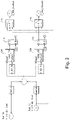
- Fig. 2 feedback from the first sensor 106 is represented by V_GEN_abc_Sense, and feedback from the second sensor 112 is represented by V_POR_abc_Sense.
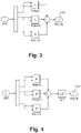
- the logic can then calculate the sum voltage/current magnitude or the voltage/current magnitude square for each of V_POR_abc_Sense and V_GEN_abc_Sense using either of the methods shown in Figs. 3-4 .
- Fig. 3 shows a method for calculating a magnitude squared
- Fig. 4 shows a method for calculating a magnitude
- Figure 5 shows an alternative method for calculating either a magnitude and/or a magnitude squared. While Fig. 5 shows a square root step, it should be appreciated that this step is optional if a magnitude is desired over a magnitude squared.
- the logic can then compare the summed magnitudes or magnitudes squared 120,122 of voltage and/or current sensed for each of three phases a,b,c of the feeder 108 for each of the first and second sensor 106,112 versus a respective threshold [e.g. V_OSF_TH and -V_OSF_TH] for each of VPOR_OSF (voltage open sense failure at the point of regulation for the second sensor) and VGEN_OSF (voltage open sense failure at the point of the first sensor), e.g. using a comparator 124.
- V_OSF_TH and -V_OSF_TH for each of VPOR_OSF (voltage open sense failure at the point of regulation for the second sensor) and VGEN_OSF (voltage open sense failure at the point of the first sensor
- VPOR_OSF can represent logic for comparing the V_OSF_Th threshold to the summed magnitudes or magnitudes squared 120,122 of voltage and/or current sensed for each of three phases a,b,c of the feeder 108 for each of the first and second sensor 106,112.
- VGEN_OSF can represent logic for comparing the -V_OSF_Th threshold to the summed magnitudes or magnitudes squared 120,112 of voltage and/or current sensed for each of three phases a,b,c of the feeder 108 for each of the first and second sensor 106,112.
- each of the VPOR_OSF and VGEN_OSF can connect through a respective latch 116 to a respective switch 118.
- the latch 116 latch can be disposed within each branch of the logic diagram as shown, so that the latch 116 can suppress a faulted sense. Once a sense has passed through latch 116, the latch 116 must be reset to resume normal two sense operation. If a fault is detected in either branch, the switches 118 can then switch off faulty feedback from the respective one of the first and second sensors 106,112 to the GCU 102.
- the logic can include transforming three phases from each of the first and second sensors 106,112 to Alpha-Beta coordinates, and then taking the magnitude of the Alpha-Beta for each, for example as shown in Fig. 5 .
- the system 100 can include filtering when deciding which of the first and/or second sensors 106,112 is experiencing fault.
- the system can filter based on whether the difference of magnitudes 120 (or magnitudes squared 122) exceeds a threshold a certain number of consecutive times.
- the filter can be a difference of magnitudes 120 (or magnitudes squared 122) is processed through an infinite impulse response (IIR) filter, for example a low pass filter.
- IIR infinite impulse response
- FIR finite impulse response
- a method 200 can comprise, at box 202, using feedback from first and second sensors 106,112 spaced apart along a feeder 108 to control a generator 104 powering a load 110 through the feeder 108.
- the method 200 can also include, at box 204, detecting a fault in one of the first and second sensors 106, 112 and continuing operation of the generator 104.
- the method 200 can include filtering when detecting a fault in one of the sensors 106,112 and deciding which sensor 106,112 is at fault, as shown at box 206.
Landscapes
- Engineering & Computer Science (AREA)
- Power Engineering (AREA)
- Testing Electric Properties And Detecting Electric Faults (AREA)
- Control Of Eletrric Generators (AREA)
- Physics & Mathematics (AREA)
- Computer Hardware Design (AREA)
- Mathematical Physics (AREA)
- Dc-Dc Converters (AREA)
- Testing Of Short-Circuits, Discontinuities, Leakage, Or Incorrect Line Connections (AREA)
Abstract
Description
- The present disclosure relates to generator control, and more particularly to fault detection for generator control.
- Sensors can be used on generator feeders to generate feedback for controlling the generator. It is possible to lose control of a generator if the sensor is defective or becomes defective, even if the generator, feeder, and loads are fully functional. One way of handling this event is to shut down the generator until the defect in the sensor can be corrected.
- The conventional techniques have been considered satisfactory for their intended purpose. However, there is an ever present need for improved systems and methods for faster fault detection and correction. This disclosure provides a solution for this need.
- A system comprises a generator control unit (GCU) configured to control a generator. The system includes a first sensor connected to provide feedback to the GCU for generator control. The first sensor is configured to sense at least one of voltage and/or current in a feeder connecting between the generator and a load. The system also includes a second sensor connected to provide feedback to the GCU for generator control. The second sensor is configured to sense at least one of voltage and/or current in the feeder connecting between the generator and the load. The first and second sensors are configured to connect to the feeder apart from one another with feeder impedance therebetween.
- The first sensor can be configured to sense at least one of voltage and/or current in each one of three phases of the feeder, and the second sensor can be configured to sense at least one of voltage and/or current in each one of three phases of the feeder.
- The system can further include the generator operatively connected to be controlled by the GCU, and the can be feeder connected to supply power from the generator to a load. The first sensor can be electrically closer to the generator than to a load end of the feeder than the second sensor relative to feeder impedance.
- The system can also include logic in the GCU, which can be configured to cause the GCU to use feedback from the first and second sensors to control the generator. The logic can be configured to detect faults in each of the first and second sensors and continue operation of the generator in the event of only one of the sensors faulting. The logic can be configured to cause the GCU to detect a discrepancy between the first and second sensors, decide whether the first sensor is at fault or whether the second sensor is at fault when detecting the discrepancy, and control the generator based on feedback from whichever of the first or second sensors are not at fault.
- Detecting a discrepancy can include comparing summed magnitudes or magnitudes squared of voltage and/or current sensed for each of three phases of the feeder for each of the first and second sensor versus a respective threshold [V_OSF_TH and -V_OSF_TH] for each of VPOR_OSF (voltage open sense failure at the point of regulation for the second sensor) and VGEN_OSF (voltage open sense failure at the point of the first sensor). VPOR_OSF can be logic for comparing the V_OSF_Th threshold to the summed magnitudes or magnitudes squared of voltage and/or current sensed for each of three phases of the feeder for each of the first and second sensor. VGEN_OSF can be logic for comparing the -V_OSF_Th threshold to the summed magnitudes or magnitudes squared of voltage and/or current sensed for each of three phases of the feeder for each of the first and second sensor.
- Each of the VPOR_OSF and VGEN_OSF can connect through a latch to a respective switch for switching off faulty feedback from the respective one of the first and second sensors to the GCU. Detecting the discrepancy can also include transforming three phases from each of the first and second sensors to Alpha-Beta coordinates, then taking the magnitude of the Alpha-Beta for each.
- The system can include filtering when deciding. The system can filter based on whether the difference of magnitudes (or magnitudes squares) exceeds a threshold a certain number of consecutive times. Additionally, or alternatively, the system can filter by difference of magnitudes (or magnitudes squares) is a processed through an infinite impulse response (IIR) filter. Additionally, or alternatively, the system can filter by difference of magnitudes (or magnitudes squares) is a processed through a finite impulse response (FIR) filter.
- A method comprises using feedback from first and second sensors spaced apart along a feeder to control a generator powering a load through the feeder. The method also includes detecting a fault in one of the first and second sensors and continuing operation of the generator.
- These and other features of the systems and methods of the subject disclosure will become more readily apparent to those skilled in the art from the following detailed description taken in conjunction with the drawings.
- So that those skilled in the art to which the subject disclosure appertains will readily understand how to make and use the devices and methods of the subject disclosure without undue experimentation, embodiments thereof will be described in detail herein below with reference to certain figures, wherein:
-
Fig. 1 is a schematic plan view of an embodiment of a generator control system constructed in accordance with the present disclosure, showing feedback control circuit; -
Fig. 2 is a schematic logic diagram showing the generator control unit ofFig. 1 ; -
Fig. 3 is a schematic logic diagram showing a method of calculating magnitudes squared; -
Fig. 4 is a schematic logic diagram showing a method of calculating magnitudes; -
Fig. 5 is a schematic logic diagram showing another method of calculating a magnitudes or magnitudes squared; -
Fig. 6 is a schematic box diagram showing a method in accordance with at least one aspect of this disclosure. - Reference will now be made to the drawings wherein like reference numerals identify similar structural features or aspects of the subject disclosure. For purposes of explanation and illustration, and not limitation, a partial view of an embodiment of a system in accordance with the disclosure is shown in
Fig. 1 and is designated generally by reference character 100. Other embodiments of systems in accordance with the disclosure, or aspects thereof, are provided inFigs. 2-5 , as will be described. The systems and methods described herein can be used to quickly determine a fault and accommodate using minimal resources. - A system 100 comprises a generator control unit (GCU) 102 that can be configured to control a
generator 104. Thegenerator 104 can be operatively connected to theGCU 102 to be controlled by theGCU 102, and thefeeder 108 can be connected to thegenerator 104 to supply power from thegenerator 104 to aload 110. The system 100 can include afirst sensor 106 connected to afeeder 108 to provide feedback to the GCU 102 for generator control. Thefirst sensor 106 can be configured to sense at least one of voltage and/or current in thefeeder 108, thefeeder 108 connecting between thegenerator 104 and theload 110. The system 100 can also include asecond sensor 112 connected to thefeeder 108 to provide feedback to the GCU 102 for generator control. Thesecond sensor 112 can also be configured to sense at least one of voltage and/or current in thefeeder 108. The first and second sensors 106,112 can be configured to connect to thefeeder 108 separated by afeeder impedance 114. - As shown in
Fig. 1 , the first sensor andsecond sensors feeder 108. For example, thefirst sensor 106 can be electrically closer to thegenerator 104 than to theload 110 end of thefeeder 108 than thesecond sensor 112 relative to thefeeder impedance 114. - Referring now to
Fig. 2 , the system 100 can also include logic in theGCU 102. The logic can include machine readable instructions, digital circuitry, analog circuitry, any combination of thereof, and/or any other suitable form of logic. The logic can be configured to cause theGCU 102 to use feedback from the first and second sensors 106,112 to control thegenerator 104. For example, the logic can be configured to detect faults in each of the first and second sensors 106,112, and even if a fault is detected, the logic can continue operation of thegenerator 104. In embodiments, the logic can be configured to cause theGCU 102 to detect a discrepancy between the first and second sensors 106,112 and decide whether thefirst sensor 106 is at fault or whether thesecond sensor 112 is at fault. After detection and determination of which sensor has faulted, the logic can then control thegenerator 104 based on feedback from whichever of the first or second sensors 106,112 are not at fault. This process will be described in more detail below. - In
Fig. 2 , feedback from thefirst sensor 106 is represented by V_GEN_abc_Sense, and feedback from thesecond sensor 112 is represented by V_POR_abc_Sense. The logic can then calculate the sum voltage/current magnitude or the voltage/current magnitude square for each of V_POR_abc_Sense and V_GEN_abc_Sense using either of the methods shown inFigs. 3-4 . For example,Fig. 3 shows a method for calculating a magnitude squared, whileFig. 4 shows a method for calculating a magnitude.Figure 5 shows an alternative method for calculating either a magnitude and/or a magnitude squared. WhileFig. 5 shows a square root step, it should be appreciated that this step is optional if a magnitude is desired over a magnitude squared. - In order to quickly detect a discrepancy, the logic can then compare the summed magnitudes or magnitudes squared 120,122 of voltage and/or current sensed for each of three phases a,b,c of the
feeder 108 for each of the first and second sensor 106,112 versus a respective threshold [e.g. V_OSF_TH and -V_OSF_TH] for each of VPOR_OSF (voltage open sense failure at the point of regulation for the second sensor) and VGEN_OSF (voltage open sense failure at the point of the first sensor), e.g. using acomparator 124. - VPOR_OSF can represent logic for comparing the V_OSF_Th threshold to the summed magnitudes or magnitudes squared 120,122 of voltage and/or current sensed for each of three phases a,b,c of the
feeder 108 for each of the first and second sensor 106,112. VGEN_OSF can represent logic for comparing the -V_OSF_Th threshold to the summed magnitudes or magnitudes squared 120,112 of voltage and/or current sensed for each of three phases a,b,c of thefeeder 108 for each of the first and second sensor 106,112. - After comparing the sensed voltage and/or current with the threshold as described above, each of the VPOR_OSF and VGEN_OSF can connect through a
respective latch 116 to arespective switch 118. Thelatch 116 latch can be disposed within each branch of the logic diagram as shown, so that thelatch 116 can suppress a faulted sense. Once a sense has passed throughlatch 116, thelatch 116 must be reset to resume normal two sense operation. If a fault is detected in either branch, theswitches 118 can then switch off faulty feedback from the respective one of the first and second sensors 106,112 to theGCU 102. Optionally, when detecting a discrepancy, the logic can include transforming three phases from each of the first and second sensors 106,112 to Alpha-Beta coordinates, and then taking the magnitude of the Alpha-Beta for each, for example as shown inFig. 5 . - The system 100 can include filtering when deciding which of the first and/or second sensors 106,112 is experiencing fault. The system can filter based on whether the difference of magnitudes 120 (or magnitudes squared 122) exceeds a threshold a certain number of consecutive times. Additionally, or alternatively, the filter can be a difference of magnitudes 120 (or magnitudes squared 122) is processed through an infinite impulse response (IIR) filter, for example a low pass filter. Additionally, or alternatively, the filter can be difference of magnitudes (or magnitudes squared 122) is processed through a finite impulse response (FIR) filter, for example a moving average filter.
- In
Fig. 6 , amethod 200 can comprise, atbox 202, using feedback from first and second sensors 106,112 spaced apart along afeeder 108 to control agenerator 104 powering aload 110 through thefeeder 108. Themethod 200 can also include, atbox 204, detecting a fault in one of the first andsecond sensors generator 104. In embodiments, themethod 200 can include filtering when detecting a fault in one of the sensors 106,112 and deciding which sensor 106,112 is at fault, as shown atbox 206. - The methods and systems of the present disclosure, as described above and shown in the drawings, provide for faster detection of faults within a feeder. Redundancy of sensors allows for optimization of logic to very quickly sense fault and correct with minimal resources. While the apparatus and methods of the subject disclosure have been shown and described, those skilled in the art will readily appreciate that changes and/or modifications may be made thereto without departing from the scope of the invention as defined by the claims.
Claims (15)
- A system comprising:a generator control unit, GCU, (102) configured to control a generator (104);a first sensor (106) connected to provide feedback to the GCU for generator control,
wherein the first sensor is configured to connect to sense at least one of voltage and/or current in a feeder connecting between the generator and a load (110); anda second sensor (112) connected to provide feedback to the GCU for generator control, wherein the second sensor is configured to sense at least one of voltage and/or current in a feeder (108) connecting between the generator and the load, wherein the first and second sensors are configured to connect to the feeder apart from one another with feeder impedance therebetween. - The system as recited in claim 1, wherein the first sensor (106) is configured to sense at least one of voltage and/or current in each one of three phases of the feeder (108).
- The system as recited in claim 1 or 2, wherein the second sensor (112) is configured to sense at least one of voltage and/or current in each one of three phases of the feeder.
- The system as recited in any preceding claim, further comprising:the generator (104) operatively connected to be controlled by the GCU; andthe feeder (108) connected to supply power from the generator to a load, wherein the first sensor is electrically closer to the generator than to a load end of the feeder than is the second sensor relative to the feeder impedance.
- The system as recited in any preceding claim, further comprising logic in the GCU configured to cause the GCU to use feedback from the first and second sensors to control the generator.
- The system as recited in claim 5, wherein the logic is configured to detect faults in each of the first and second sensors and continue operation of the generator in the event of only one of the sensors faulting.
- The system as recited in claim 6, wherein the logic is configured to cause the GCU to:detect a discrepancy between the first and second sensors,decide whether the first sensor is at fault or whether the second sensor is at fault when detecting the discrepancy, andcontrol the generator based on feedback from whichever of the first or second sensors are not at fault.
- The system as recited in claim 7, wherein detecting a discrepancy includes comparing summed magnitudes or magnitudes squared of voltage and/or current sensed for each of three phases of the feeder for each of the first and second sensor versus a respective threshold [V_OSF_TH and-V_OSF_TH] for each of VPOR_OSF (voltage open sense failure at the point of regulation for the second sensor) and VGEN_OSF (voltage open sense failure at the point of the first sensor), wherein VPOR_OSF is logic for comparing the V_OSF_Th threshold to the summed magnitudes or magnitudes squared of voltage and/or current sensed for each of three phases of the feeder for each of the first and second sensor, and wherein VGEN_OSF is logic for comparing the -V_OSF_Th threshold to the summed magnitudes or magnitudes squared of voltage and/or current sensed for each of three phases of the feeder for each of the first and second sensor.
- The system as recited in claim 8, wherein each of the VPOR_OSF and VGEN_OSF connects through a latch to a respective switch for switching off faulty feedback from the respective one of the first and second sensors to the GCU.
- The system as recited in claim 7, 8 or 9, wherein detecting the discrepancy includes transforming three phases from each of the first and second sensors to Alpha-Beta coordinates, then taking the magnitude of the Alpha-Beta for each.
- The system as recited in any of claims 7 to 10, further comprising filtering when deciding, wherein filtering includes at least one of:difference of magnitudes (or magnitudes squares) has to exceed a threshold a certain number of consecutive times;difference of magnitudes (or magnitudes squares) is processed through an infinite impulse response (IIR) filter; and/ordifference of magnitudes (or magnitudes squares) is processed through a finite impulse response (FIR) filter.
- A method comprising:using feedback from first (106) and second (112) sensors spaced apart along a feeder (108) to control a generator (104) powering a load (110) through the feeder; anddetecting a fault in one of the first and second sensors and continuing operation of the generator.
- The method as recited in claim 12, wherein detecting a fault in one of the first and second sensors and continuing operation of the generator includes:detecting a discrepancy between the first and second sensors;deciding whether the first sensor is at fault or whether the second sensor is at fault when detecting the discrepancy; andcontrolling the generator based on feedback from whichever of the first or second sensors are not at fault.
- The method as recited in claim 13, wherein detecting a discrepancy includes comparing summing magnitudes or magnitudes squared of voltage and/or current sensed for each of three phases of the feeder for each of the first and second sensor versus a respective threshold [V_OSF_TH and-V_OSF_TH] for each of VPOR_OSF (voltage open sense failure at the point of regulation for the second sensor) and VGEN_OSF (voltage open sense failure at the point of the first sensor), wherein VPOR_OSF is logic for comparing the V_OSF_Th threshold to the summed magnitudes or magnitudes squared of voltage and/or current sensed for each of three phases of the feeder for each of the first and second sensor, and wherein VGEN_OSF is logic for comparing the -V_OSF_Th threshold to the summed magnitudes or magnitudes squared of voltage and/or current sensed for each of three phases of the feeder for each of the first and second sensor.
- The method as recited in claim 14, further comprising filtering when deciding, wherein filtering includes at least one of:difference of magnitudes (or magnitudes squares) has to exceed a threshold a certain number of consecutive times;difference of magnitudes (or magnitudes squares) is processed through an infinite impulse response (IIR) filter; and/ordifference of magnitudes (or magnitudes squares) is processed through a finite impulse response (FIR) filter.
Priority Applications (1)
| Application Number | Priority Date | Filing Date | Title |
|---|---|---|---|
| EP24172712.2A EP4383493A3 (en) | 2021-01-04 | 2022-01-04 | Fast por trim correction |
Applications Claiming Priority (1)
| Application Number | Priority Date | Filing Date | Title |
|---|---|---|---|
| US17/141,012 US12034396B2 (en) | 2021-01-04 | 2021-01-04 | Fast POR trim correction |
Related Child Applications (1)
| Application Number | Title | Priority Date | Filing Date |
|---|---|---|---|
| EP24172712.2A Division EP4383493A3 (en) | 2021-01-04 | 2022-01-04 | Fast por trim correction |
Publications (2)
| Publication Number | Publication Date |
|---|---|
| EP4024696A1 true EP4024696A1 (en) | 2022-07-06 |
| EP4024696B1 EP4024696B1 (en) | 2024-05-22 |
Family
ID=79230591
Family Applications (2)
| Application Number | Title | Priority Date | Filing Date |
|---|---|---|---|
| EP22150102.6A Active EP4024696B1 (en) | 2021-01-04 | 2022-01-04 | Fast por trim correction and method |
| EP24172712.2A Pending EP4383493A3 (en) | 2021-01-04 | 2022-01-04 | Fast por trim correction |
Family Applications After (1)
| Application Number | Title | Priority Date | Filing Date |
|---|---|---|---|
| EP24172712.2A Pending EP4383493A3 (en) | 2021-01-04 | 2022-01-04 | Fast por trim correction |
Country Status (2)
| Country | Link |
|---|---|
| US (1) | US12034396B2 (en) |
| EP (2) | EP4024696B1 (en) |
Citations (3)
| Publication number | Priority date | Publication date | Assignee | Title |
|---|---|---|---|---|
| US5488532A (en) * | 1993-10-27 | 1996-01-30 | Sundstrand Corporation | System of protection for electric power distribution failures |
| EP2658062A2 (en) * | 2012-04-25 | 2013-10-30 | The Boeing Company | Fault protection for aircraft power systems |
| US20200021111A1 (en) * | 2018-07-11 | 2020-01-16 | The Boeing Company | Simultaneous Bidirectional Power Usage of Generator Power Feeders |
Family Cites Families (10)
| Publication number | Priority date | Publication date | Assignee | Title |
|---|---|---|---|---|
| US6377086B1 (en) | 1999-10-05 | 2002-04-23 | Agere Systems Guardian Corp. | Low power dual-voltage sense circuit buffer |
| KR100394757B1 (en) | 2000-09-21 | 2003-08-14 | 가부시끼가이샤 도시바 | Semiconductor device |
| US6504486B1 (en) | 2000-11-06 | 2003-01-07 | Sun Microsystems, Inc. | Dual voltage sense cell for input/output dynamic termination logic |
| US6353568B1 (en) | 2000-12-29 | 2002-03-05 | Lsi Logic Corporation | Dual threshold voltage sense amplifier |
| US6815983B2 (en) | 2003-01-28 | 2004-11-09 | Xicor, Inc. | Analog floating gate voltage sense during dual conduction programming |
| CN105425887B (en) | 2015-12-30 | 2017-04-05 | 广西师范大学 | A kind of recoverable low power consumption voltage a reference source with electrification reset |
| CN205263697U (en) | 2015-12-30 | 2016-05-25 | 广西师范大学 | Take recoverable low -power consumption voltage reference source of replying position by cable |
| US10613604B2 (en) | 2016-12-22 | 2020-04-07 | Texas Instruments Incorporated | On chip power on reset with integrated supervisory functions for a functional safety system |
| EP3379273B1 (en) * | 2017-03-22 | 2019-09-18 | Siemens Aktiengesellschaft | Method, device and system for determining the location a fault on a line of an electrical energy supply network |
| JP7117904B2 (en) | 2018-06-11 | 2022-08-15 | 三菱電機株式会社 | Power semiconductor equipment |
-
2021
- 2021-01-04 US US17/141,012 patent/US12034396B2/en active Active
-
2022
- 2022-01-04 EP EP22150102.6A patent/EP4024696B1/en active Active
- 2022-01-04 EP EP24172712.2A patent/EP4383493A3/en active Pending
Patent Citations (3)
| Publication number | Priority date | Publication date | Assignee | Title |
|---|---|---|---|---|
| US5488532A (en) * | 1993-10-27 | 1996-01-30 | Sundstrand Corporation | System of protection for electric power distribution failures |
| EP2658062A2 (en) * | 2012-04-25 | 2013-10-30 | The Boeing Company | Fault protection for aircraft power systems |
| US20200021111A1 (en) * | 2018-07-11 | 2020-01-16 | The Boeing Company | Simultaneous Bidirectional Power Usage of Generator Power Feeders |
Also Published As
| Publication number | Publication date |
|---|---|
| EP4383493A3 (en) | 2024-09-04 |
| EP4383493A2 (en) | 2024-06-12 |
| US12034396B2 (en) | 2024-07-09 |
| US20220216815A1 (en) | 2022-07-07 |
| EP4024696B1 (en) | 2024-05-22 |
Similar Documents
| Publication | Publication Date | Title |
|---|---|---|
| US10714288B2 (en) | Relay device | |
| JP6105705B2 (en) | Abnormality detection device and power conditioner for grid interconnection relay | |
| US7619866B2 (en) | Electric trip device provided with monitoring means, circuit breaker comprising one such trip device and method of monitoring | |
| US20190140438A1 (en) | Fuse system for at least one load of a vehicle | |
| US11834193B2 (en) | Dual pole switch detection circuit | |
| EP4024696B1 (en) | Fast por trim correction and method | |
| WO2017102692A1 (en) | Ground fault detection and interrupt system | |
| JP2011107807A (en) | Process control device | |
| US20120098345A1 (en) | Minimal interruption dc power supply | |
| CN115051461B (en) | Power supply line control device and UPS system | |
| EP2595268B1 (en) | Minimal interruption DC power supply | |
| EP0887628A1 (en) | Fail-safe system | |
| JP3000862B2 (en) | Instantaneous voltage drop countermeasure device | |
| CN103904773B (en) | The shunting device of controller switching equipment and the control method of distribution network | |
| CN115912599A (en) | A dual power supply switching device and method | |
| CN100582797C (en) | Method and system for identifying a faulted phase | |
| EP4339625A1 (en) | Improvements in or relating to sensors for use in hvdc power transmission networks | |
| JP7038648B2 (en) | Control device | |
| JP2010259300A (en) | Electric vehicle control device and test method thereof | |
| JP3794208B2 (en) | Protection device for grid interconnection system | |
| JP3899215B2 (en) | Distribution system accident recovery method | |
| JPS60257798A (en) | Excitation controller for synchronous generator | |
| JPH08289475A (en) | Fault detection method and system switching method for inverter parallel operation system | |
| TWM484242U (en) | Three-phase dual power switching system | |
| JPH07177653A (en) | Grid interconnection protection device |
Legal Events
| Date | Code | Title | Description |
|---|---|---|---|
| PUAI | Public reference made under article 153(3) epc to a published international application that has entered the european phase |
Free format text: ORIGINAL CODE: 0009012 |
|
| STAA | Information on the status of an ep patent application or granted ep patent |
Free format text: STATUS: THE APPLICATION HAS BEEN PUBLISHED |
|
| AK | Designated contracting states |
Kind code of ref document: A1 Designated state(s): AL AT BE BG CH CY CZ DE DK EE ES FI FR GB GR HR HU IE IS IT LI LT LU LV MC MK MT NL NO PL PT RO RS SE SI SK SM TR |
|
| STAA | Information on the status of an ep patent application or granted ep patent |
Free format text: STATUS: REQUEST FOR EXAMINATION WAS MADE |
|
| 17P | Request for examination filed |
Effective date: 20230109 |
|
| RBV | Designated contracting states (corrected) |
Designated state(s): AL AT BE BG CH CY CZ DE DK EE ES FI FR GB GR HR HU IE IS IT LI LT LU LV MC MK MT NL NO PL PT RO RS SE SI SK SM TR |
|
| GRAP | Despatch of communication of intention to grant a patent |
Free format text: ORIGINAL CODE: EPIDOSNIGR1 |
|
| STAA | Information on the status of an ep patent application or granted ep patent |
Free format text: STATUS: GRANT OF PATENT IS INTENDED |
|
| RIC1 | Information provided on ipc code assigned before grant |
Ipc: H02H 7/06 20060101ALI20231204BHEP Ipc: H02H 7/26 20060101ALI20231204BHEP Ipc: H02P 9/00 20060101AFI20231204BHEP |
|
| INTG | Intention to grant announced |
Effective date: 20231220 |
|
| GRAS | Grant fee paid |
Free format text: ORIGINAL CODE: EPIDOSNIGR3 |
|
| GRAA | (expected) grant |
Free format text: ORIGINAL CODE: 0009210 |
|
| STAA | Information on the status of an ep patent application or granted ep patent |
Free format text: STATUS: THE PATENT HAS BEEN GRANTED |
|
| AK | Designated contracting states |
Kind code of ref document: B1 Designated state(s): AL AT BE BG CH CY CZ DE DK EE ES FI FR GB GR HR HU IE IS IT LI LT LU LV MC MK MT NL NO PL PT RO RS SE SI SK SM TR |
|
| REG | Reference to a national code |
Ref country code: GB Ref legal event code: FG4D |
|
| REG | Reference to a national code |
Ref country code: CH Ref legal event code: EP |
|
| REG | Reference to a national code |
Ref country code: DE Ref legal event code: R096 Ref document number: 602022003514 Country of ref document: DE |
|
| REG | Reference to a national code |
Ref country code: IE Ref legal event code: FG4D |
|
| REG | Reference to a national code |
Ref country code: LT Ref legal event code: MG9D |
|
| REG | Reference to a national code |
Ref country code: NL Ref legal event code: MP Effective date: 20240522 |
|
| PG25 | Lapsed in a contracting state [announced via postgrant information from national office to epo] |
Ref country code: IS Free format text: LAPSE BECAUSE OF FAILURE TO SUBMIT A TRANSLATION OF THE DESCRIPTION OR TO PAY THE FEE WITHIN THE PRESCRIBED TIME-LIMIT Effective date: 20240922 |
|
| PG25 | Lapsed in a contracting state [announced via postgrant information from national office to epo] |
Ref country code: BG Free format text: LAPSE BECAUSE OF FAILURE TO SUBMIT A TRANSLATION OF THE DESCRIPTION OR TO PAY THE FEE WITHIN THE PRESCRIBED TIME-LIMIT Effective date: 20240522 |
|
| PG25 | Lapsed in a contracting state [announced via postgrant information from national office to epo] |
Ref country code: HR Free format text: LAPSE BECAUSE OF FAILURE TO SUBMIT A TRANSLATION OF THE DESCRIPTION OR TO PAY THE FEE WITHIN THE PRESCRIBED TIME-LIMIT Effective date: 20240522 Ref country code: FI Free format text: LAPSE BECAUSE OF FAILURE TO SUBMIT A TRANSLATION OF THE DESCRIPTION OR TO PAY THE FEE WITHIN THE PRESCRIBED TIME-LIMIT Effective date: 20240522 |
|
| PG25 | Lapsed in a contracting state [announced via postgrant information from national office to epo] |
Ref country code: GR Free format text: LAPSE BECAUSE OF FAILURE TO SUBMIT A TRANSLATION OF THE DESCRIPTION OR TO PAY THE FEE WITHIN THE PRESCRIBED TIME-LIMIT Effective date: 20240823 |
|
| PG25 | Lapsed in a contracting state [announced via postgrant information from national office to epo] |
Ref country code: PT Free format text: LAPSE BECAUSE OF FAILURE TO SUBMIT A TRANSLATION OF THE DESCRIPTION OR TO PAY THE FEE WITHIN THE PRESCRIBED TIME-LIMIT Effective date: 20240923 |
|
| REG | Reference to a national code |
Ref country code: AT Ref legal event code: MK05 Ref document number: 1689582 Country of ref document: AT Kind code of ref document: T Effective date: 20240522 |
|
| PG25 | Lapsed in a contracting state [announced via postgrant information from national office to epo] |
Ref country code: NL Free format text: LAPSE BECAUSE OF FAILURE TO SUBMIT A TRANSLATION OF THE DESCRIPTION OR TO PAY THE FEE WITHIN THE PRESCRIBED TIME-LIMIT Effective date: 20240522 |
|
| PG25 | Lapsed in a contracting state [announced via postgrant information from national office to epo] |
Ref country code: ES Free format text: LAPSE BECAUSE OF FAILURE TO SUBMIT A TRANSLATION OF THE DESCRIPTION OR TO PAY THE FEE WITHIN THE PRESCRIBED TIME-LIMIT Effective date: 20240522 |
|
| PG25 | Lapsed in a contracting state [announced via postgrant information from national office to epo] |
Ref country code: AT Free format text: LAPSE BECAUSE OF FAILURE TO SUBMIT A TRANSLATION OF THE DESCRIPTION OR TO PAY THE FEE WITHIN THE PRESCRIBED TIME-LIMIT Effective date: 20240522 |
|
| PG25 | Lapsed in a contracting state [announced via postgrant information from national office to epo] |
Ref country code: PL Free format text: LAPSE BECAUSE OF FAILURE TO SUBMIT A TRANSLATION OF THE DESCRIPTION OR TO PAY THE FEE WITHIN THE PRESCRIBED TIME-LIMIT Effective date: 20240522 |
|
| PG25 | Lapsed in a contracting state [announced via postgrant information from national office to epo] |
Ref country code: LV Free format text: LAPSE BECAUSE OF FAILURE TO SUBMIT A TRANSLATION OF THE DESCRIPTION OR TO PAY THE FEE WITHIN THE PRESCRIBED TIME-LIMIT Effective date: 20240522 |
|
| PG25 | Lapsed in a contracting state [announced via postgrant information from national office to epo] |
Ref country code: PT Free format text: LAPSE BECAUSE OF FAILURE TO SUBMIT A TRANSLATION OF THE DESCRIPTION OR TO PAY THE FEE WITHIN THE PRESCRIBED TIME-LIMIT Effective date: 20240923 Ref country code: PL Free format text: LAPSE BECAUSE OF FAILURE TO SUBMIT A TRANSLATION OF THE DESCRIPTION OR TO PAY THE FEE WITHIN THE PRESCRIBED TIME-LIMIT Effective date: 20240522 Ref country code: NO Free format text: LAPSE BECAUSE OF FAILURE TO SUBMIT A TRANSLATION OF THE DESCRIPTION OR TO PAY THE FEE WITHIN THE PRESCRIBED TIME-LIMIT Effective date: 20240822 Ref country code: NL Free format text: LAPSE BECAUSE OF FAILURE TO SUBMIT A TRANSLATION OF THE DESCRIPTION OR TO PAY THE FEE WITHIN THE PRESCRIBED TIME-LIMIT Effective date: 20240522 Ref country code: LV Free format text: LAPSE BECAUSE OF FAILURE TO SUBMIT A TRANSLATION OF THE DESCRIPTION OR TO PAY THE FEE WITHIN THE PRESCRIBED TIME-LIMIT Effective date: 20240522 Ref country code: IS Free format text: LAPSE BECAUSE OF FAILURE TO SUBMIT A TRANSLATION OF THE DESCRIPTION OR TO PAY THE FEE WITHIN THE PRESCRIBED TIME-LIMIT Effective date: 20240922 Ref country code: HR Free format text: LAPSE BECAUSE OF FAILURE TO SUBMIT A TRANSLATION OF THE DESCRIPTION OR TO PAY THE FEE WITHIN THE PRESCRIBED TIME-LIMIT Effective date: 20240522 Ref country code: GR Free format text: LAPSE BECAUSE OF FAILURE TO SUBMIT A TRANSLATION OF THE DESCRIPTION OR TO PAY THE FEE WITHIN THE PRESCRIBED TIME-LIMIT Effective date: 20240823 Ref country code: FI Free format text: LAPSE BECAUSE OF FAILURE TO SUBMIT A TRANSLATION OF THE DESCRIPTION OR TO PAY THE FEE WITHIN THE PRESCRIBED TIME-LIMIT Effective date: 20240522 Ref country code: ES Free format text: LAPSE BECAUSE OF FAILURE TO SUBMIT A TRANSLATION OF THE DESCRIPTION OR TO PAY THE FEE WITHIN THE PRESCRIBED TIME-LIMIT Effective date: 20240522 Ref country code: BG Free format text: LAPSE BECAUSE OF FAILURE TO SUBMIT A TRANSLATION OF THE DESCRIPTION OR TO PAY THE FEE WITHIN THE PRESCRIBED TIME-LIMIT Effective date: 20240522 Ref country code: AT Free format text: LAPSE BECAUSE OF FAILURE TO SUBMIT A TRANSLATION OF THE DESCRIPTION OR TO PAY THE FEE WITHIN THE PRESCRIBED TIME-LIMIT Effective date: 20240522 Ref country code: RS Free format text: LAPSE BECAUSE OF FAILURE TO SUBMIT A TRANSLATION OF THE DESCRIPTION OR TO PAY THE FEE WITHIN THE PRESCRIBED TIME-LIMIT Effective date: 20240822 |
|
| PG25 | Lapsed in a contracting state [announced via postgrant information from national office to epo] |
Ref country code: DK Free format text: LAPSE BECAUSE OF FAILURE TO SUBMIT A TRANSLATION OF THE DESCRIPTION OR TO PAY THE FEE WITHIN THE PRESCRIBED TIME-LIMIT Effective date: 20240522 |
|
| PG25 | Lapsed in a contracting state [announced via postgrant information from national office to epo] |
Ref country code: EE Free format text: LAPSE BECAUSE OF FAILURE TO SUBMIT A TRANSLATION OF THE DESCRIPTION OR TO PAY THE FEE WITHIN THE PRESCRIBED TIME-LIMIT Effective date: 20240522 |
|
| PG25 | Lapsed in a contracting state [announced via postgrant information from national office to epo] |
Ref country code: CZ Free format text: LAPSE BECAUSE OF FAILURE TO SUBMIT A TRANSLATION OF THE DESCRIPTION OR TO PAY THE FEE WITHIN THE PRESCRIBED TIME-LIMIT Effective date: 20240522 |
|
| PG25 | Lapsed in a contracting state [announced via postgrant information from national office to epo] |
Ref country code: RO Free format text: LAPSE BECAUSE OF FAILURE TO SUBMIT A TRANSLATION OF THE DESCRIPTION OR TO PAY THE FEE WITHIN THE PRESCRIBED TIME-LIMIT Effective date: 20240522 Ref country code: SK Free format text: LAPSE BECAUSE OF FAILURE TO SUBMIT A TRANSLATION OF THE DESCRIPTION OR TO PAY THE FEE WITHIN THE PRESCRIBED TIME-LIMIT Effective date: 20240522 |
|
| PG25 | Lapsed in a contracting state [announced via postgrant information from national office to epo] |
Ref country code: SK Free format text: LAPSE BECAUSE OF FAILURE TO SUBMIT A TRANSLATION OF THE DESCRIPTION OR TO PAY THE FEE WITHIN THE PRESCRIBED TIME-LIMIT Effective date: 20240522 Ref country code: RO Free format text: LAPSE BECAUSE OF FAILURE TO SUBMIT A TRANSLATION OF THE DESCRIPTION OR TO PAY THE FEE WITHIN THE PRESCRIBED TIME-LIMIT Effective date: 20240522 Ref country code: EE Free format text: LAPSE BECAUSE OF FAILURE TO SUBMIT A TRANSLATION OF THE DESCRIPTION OR TO PAY THE FEE WITHIN THE PRESCRIBED TIME-LIMIT Effective date: 20240522 Ref country code: DK Free format text: LAPSE BECAUSE OF FAILURE TO SUBMIT A TRANSLATION OF THE DESCRIPTION OR TO PAY THE FEE WITHIN THE PRESCRIBED TIME-LIMIT Effective date: 20240522 Ref country code: CZ Free format text: LAPSE BECAUSE OF FAILURE TO SUBMIT A TRANSLATION OF THE DESCRIPTION OR TO PAY THE FEE WITHIN THE PRESCRIBED TIME-LIMIT Effective date: 20240522 |
|
| PG25 | Lapsed in a contracting state [announced via postgrant information from national office to epo] |
Ref country code: IT Free format text: LAPSE BECAUSE OF FAILURE TO SUBMIT A TRANSLATION OF THE DESCRIPTION OR TO PAY THE FEE WITHIN THE PRESCRIBED TIME-LIMIT Effective date: 20240522 |
|
| REG | Reference to a national code |
Ref country code: DE Ref legal event code: R097 Ref document number: 602022003514 Country of ref document: DE |
|
| PLBE | No opposition filed within time limit |
Free format text: ORIGINAL CODE: 0009261 |
|
| STAA | Information on the status of an ep patent application or granted ep patent |
Free format text: STATUS: NO OPPOSITION FILED WITHIN TIME LIMIT |
|
| PG25 | Lapsed in a contracting state [announced via postgrant information from national office to epo] |
Ref country code: SI Free format text: LAPSE BECAUSE OF FAILURE TO SUBMIT A TRANSLATION OF THE DESCRIPTION OR TO PAY THE FEE WITHIN THE PRESCRIBED TIME-LIMIT Effective date: 20240522 |
|
| 26N | No opposition filed |
Effective date: 20250225 |
|
| REG | Reference to a national code |
Ref country code: CH Ref legal event code: PL |
|
| PG25 | Lapsed in a contracting state [announced via postgrant information from national office to epo] |
Ref country code: SE Free format text: LAPSE BECAUSE OF FAILURE TO SUBMIT A TRANSLATION OF THE DESCRIPTION OR TO PAY THE FEE WITHIN THE PRESCRIBED TIME-LIMIT Effective date: 20240522 |
|
| PG25 | Lapsed in a contracting state [announced via postgrant information from national office to epo] |
Ref country code: MC Free format text: LAPSE BECAUSE OF FAILURE TO SUBMIT A TRANSLATION OF THE DESCRIPTION OR TO PAY THE FEE WITHIN THE PRESCRIBED TIME-LIMIT Effective date: 20240522 Ref country code: LU Free format text: LAPSE BECAUSE OF NON-PAYMENT OF DUE FEES Effective date: 20250104 |
|
| PG25 | Lapsed in a contracting state [announced via postgrant information from national office to epo] |
Ref country code: BE Free format text: LAPSE BECAUSE OF NON-PAYMENT OF DUE FEES Effective date: 20250131 |
|
| PG25 | Lapsed in a contracting state [announced via postgrant information from national office to epo] |
Ref country code: CH Free format text: LAPSE BECAUSE OF NON-PAYMENT OF DUE FEES Effective date: 20250131 |
|
| REG | Reference to a national code |
Ref country code: BE Ref legal event code: MM Effective date: 20250131 |
|
| PGFP | Annual fee paid to national office [announced via postgrant information from national office to epo] |
Ref country code: GB Payment date: 20251217 Year of fee payment: 5 |
|
| PGFP | Annual fee paid to national office [announced via postgrant information from national office to epo] |
Ref country code: FR Payment date: 20251217 Year of fee payment: 5 |
|
| PG25 | Lapsed in a contracting state [announced via postgrant information from national office to epo] |
Ref country code: IE Free format text: LAPSE BECAUSE OF NON-PAYMENT OF DUE FEES Effective date: 20250104 |
|
| PGFP | Annual fee paid to national office [announced via postgrant information from national office to epo] |
Ref country code: DE Payment date: 20251217 Year of fee payment: 5 |