EP4024633A1 - Connecteur auxiliaire compact - Google Patents
Connecteur auxiliaire compact Download PDFInfo
- Publication number
- EP4024633A1 EP4024633A1 EP21214863.9A EP21214863A EP4024633A1 EP 4024633 A1 EP4024633 A1 EP 4024633A1 EP 21214863 A EP21214863 A EP 21214863A EP 4024633 A1 EP4024633 A1 EP 4024633A1
- Authority
- EP
- European Patent Office
- Prior art keywords
- connector
- bushing
- assembly
- assemblies
- switchgear
- Prior art date
- Legal status (The legal status is an assumption and is not a legal conclusion. Google has not performed a legal analysis and makes no representation as to the accuracy of the status listed.)
- Pending
Links
Images


Classifications
-
- H—ELECTRICITY
- H02—GENERATION; CONVERSION OR DISTRIBUTION OF ELECTRIC POWER
- H02B—BOARDS, SUBSTATIONS OR SWITCHING ARRANGEMENTS FOR THE SUPPLY OR DISTRIBUTION OF ELECTRIC POWER
- H02B11/00—Switchgear having carriage withdrawable for isolation
- H02B11/02—Details
- H02B11/04—Isolating-contacts, e.g. mountings or shieldings
-
- H—ELECTRICITY
- H01—ELECTRIC ELEMENTS
- H01R—ELECTRICALLY-CONDUCTIVE CONNECTIONS; STRUCTURAL ASSOCIATIONS OF A PLURALITY OF MUTUALLY-INSULATED ELECTRICAL CONNECTING ELEMENTS; COUPLING DEVICES; CURRENT COLLECTORS
- H01R43/00—Apparatus or processes specially adapted for manufacturing, assembling, maintaining, or repairing of line connectors or current collectors or for joining electric conductors
- H01R43/26—Apparatus or processes specially adapted for manufacturing, assembling, maintaining, or repairing of line connectors or current collectors or for joining electric conductors for engaging or disengaging the two parts of a coupling device
-
- H—ELECTRICITY
- H01—ELECTRIC ELEMENTS
- H01R—ELECTRICALLY-CONDUCTIVE CONNECTIONS; STRUCTURAL ASSOCIATIONS OF A PLURALITY OF MUTUALLY-INSULATED ELECTRICAL CONNECTING ELEMENTS; COUPLING DEVICES; CURRENT COLLECTORS
- H01R13/00—Details of coupling devices of the kinds covered by groups H01R12/70 or H01R24/00 - H01R33/00
- H01R13/02—Contact members
-
- H—ELECTRICITY
- H01—ELECTRIC ELEMENTS
- H01R—ELECTRICALLY-CONDUCTIVE CONNECTIONS; STRUCTURAL ASSOCIATIONS OF A PLURALITY OF MUTUALLY-INSULATED ELECTRICAL CONNECTING ELEMENTS; COUPLING DEVICES; CURRENT COLLECTORS
- H01R13/00—Details of coupling devices of the kinds covered by groups H01R12/70 or H01R24/00 - H01R33/00
- H01R13/46—Bases; Cases
- H01R13/53—Bases or cases for heavy duty; Bases or cases for high voltage with means for preventing corona or arcing
-
- H—ELECTRICITY
- H02—GENERATION; CONVERSION OR DISTRIBUTION OF ELECTRIC POWER
- H02B—BOARDS, SUBSTATIONS OR SWITCHING ARRANGEMENTS FOR THE SUPPLY OR DISTRIBUTION OF ELECTRIC POWER
- H02B1/00—Frameworks, boards, panels, desks, casings; Details of substations or switching arrangements
- H02B1/20—Bus-bar or other wiring layouts, e.g. in cubicles, in switchyards
- H02B1/21—Bus-bar arrangements for rack-mounted devices with withdrawable units
-
- H—ELECTRICITY
- H02—GENERATION; CONVERSION OR DISTRIBUTION OF ELECTRIC POWER
- H02B—BOARDS, SUBSTATIONS OR SWITCHING ARRANGEMENTS FOR THE SUPPLY OR DISTRIBUTION OF ELECTRIC POWER
- H02B11/00—Switchgear having carriage withdrawable for isolation
- H02B11/26—Arrangements of fuses, resistors, voltage arresters or the like
-
- H—ELECTRICITY
- H02—GENERATION; CONVERSION OR DISTRIBUTION OF ELECTRIC POWER
- H02B—BOARDS, SUBSTATIONS OR SWITCHING ARRANGEMENTS FOR THE SUPPLY OR DISTRIBUTION OF ELECTRIC POWER
- H02B13/00—Arrangement of switchgear in which switches are enclosed in, or structurally associated with, a casing, e.g. cubicle
- H02B13/02—Arrangement of switchgear in which switches are enclosed in, or structurally associated with, a casing, e.g. cubicle with metal casing
- H02B13/035—Gas-insulated switchgear
- H02B13/0358—Connections to in or out conductors
Definitions
- the present disclosure relates to cable and bus assembly for a switchgear assembly, and more particularly, to a compact connector assembly for a switchgear assembly.
- MV switchgear voltage and control power (CP) transformers may be mounted vertically next to each other in a compartment(s) (e.g., a cubicle(s)) of a cabinet of a switchgear (also referred to as a switchgear assembly).
- the primary connection to these transformers is typically cables or buses, which are connected to the line or load side bus within the switchgear.
- a bus or cable connection is also made between each component.
- These bus or cable connections in 15,000 volt applications may require a certain air gap or insulating means to properly manage the required electrical clearances. Because of the complexity of these bus and cable connections, the primary compartment or area designated for making these connections can have a depth of at least 14 to 15 inches.
- the connector assembly can include first and second bushing assemblies.
- Each of the first and second bushing assemblies can include: a bushing having opposing first and second open ends with a cavity extending therethrough, the cavity being separated by a wall into first and second cavities which open to first and second open ends respectively, the wall having an opening extending between the first and second cavities, the bushing formed of an insulating material; a connector formed of a conductive material and arranged in the cavity, the connector having a portion extending through the opening of the interior wall, the connector having a first end with a first terminal in the first cavity of the bushing and an opposing second end in the second cavity; and a flexible joint cover connectable over a portion of the bushing to enclose the second cavity with the second end of the connector, the joint insulator having a first slot through which to receive a conductor from a line or load bus for connection
- the second end of the connector can include at least two second terminals separated from each other.
- the conductive cable can be connected between one of the two second terminals of the first busing assembly and one of the two second terminals of the second busing assembly.
- the first terminal of the connector for each of the first and second bushing assemblies can be configured to connect to a terminal of a device in a compartment of a switchgear cabinet of a switchgear assembly.
- the first device can be a control power transformer or a voltage transformer.
- the first and second bushing assemblies along with the tubing can utilize 5.5 or fewer inches in depth of a primary compartment of the switchgear cabinet to electrically connect a line or load bus to the first device.
- the first and second bushing assemblies together with the tubing can be configured to operate in a voltage class of 15kV, 95kV Basic Insulation Level (BIL).
- the flexible joint cover can be a polyvinyl chloride (PVC) boot which is detachably connectable over the portion of the bushing to enclose the second cavity with the second end.
- the tubing can be a phenolic tube.
- Each connector of the first and second bushing assemblies can have a Z-shape.
- a switchgear assembly can include: a switchgear cabinet including an auxiliary compartment, a cable compartment and a bus bar compartment; a multi-phase power bus system including line and load buses for distributing multi-phase power; a first device in the auxiliary compartment of the switchgear cabinet; and a plurality of the connector assemblies each for a respective power phase, each of the connecter assemblies having the first terminal of the connector of one of the first or second bushing assembly connected to the first device for a respective power phase and the second end of the connector of the first or second bushing assembly connected to a respective power phase of the line or load bus of the multi-phase power bus system.
- the switchgear assembly can further include a second device in the auxiliary compartment of the switchgear cabinet, and the first and second devices can be mounted vertically next to one another in the auxiliary compartment.
- Each of the connector assemblies can have the first terminal of the other one of the first or second bushing assembly connected to the second device for a respective power phase.
- the first device can be a control power transformer and the second device is a voltage transformer.
- the first and second bushing assemblies along with the tubing can utilize 5.5 or fewer inches in depth of the switchgear cabinet to electrically connect a line or load bus to the first device.
- Each of the connector assemblies can be configured to operate in a voltage class of 15kV, 95kV Basic Insulation Level (BIL).
- Fig. 1 illustrates a partial cross-sectional view of a switchgear assembly including a compact auxiliary connector(s) in a primary compartment of a switchgear cabinet, in accordance with an embodiment described herein.
- Fig. 2 illustrates an enlarged partial cross-sectional view of a compact auxiliary connector(s) of Fig. 1 providing live connection between an auxiliary device and a bus, in accordance with an embodiment described herein.
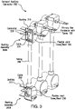
- Fig. 3 illustrates a perspective view of a plurality of compact auxiliary connector(s) of Fig. 1 with a portion of bushing assemblies of one of the compact auxiliary connectors cut out to provide an internal view of the connectors and components therein, in accordance with an embodiment described herein.
- Fig. 4 illustrates a cross-sectional view of the bushing assembly for a compact auxiliary connector of Fig. 1 , in accordance with an embodiment described herein.
- a compact auxiliary connector can include two bushings each with an electrical connector(s), and a tubing (or “tube") connected between the two bushings to insulate an electrical cable, which is connected between electrical connectors of the two bushings.
- the electrical connector of each of the two bushings can be connected to an electrical device, a bus (e.g., for line or load) or a combination thereof, according to the desired connection configuration.
- Each bushing may also include a flexible joint cover, such as a boot, to cover the connection of the bushing connectors to a bus, such as a primary bus.
- the compact auxiliary connector can manage live connections between auxiliary or other device(s) and line/load buses in a switchgear cabinet (or enclosure) of a switchgear assembly.
- the bushings, tubing and flexible joint cover can be formed of insulating materials having desired dielectric strength according to the voltage applications.
- the compact auxiliary connector of the present disclosure can allow a significant reduction in parts and compartment size for supporting, for example, medium voltage primary connections to auxiliary transformers. This reduction is valuable in allowing a reduced equipment depth while maintaining a safe and reliable live part connection in small enclosures.
- the use of such compact auxiliary connectors as described herein can be more economical than using increased enclosure size with bus bars and insulators.
- the design of the connector assembly can also sufficiently manage strike and tracking distances and dielectric strength at desired rated voltage, such as for medium or other voltage applications (e.g., 15kV, 95kV Basic Insulation Level (BIL) applications).
- the compact auxiliary connector can also allow live parts to be safely mounted within a compartment of 5.5 inches (or 139.7 mm) of grounded metal.
- the compact auxiliary connector can provide adequate air clearances between live parts and grounded metal to avoid dangerous potential partial discharge issues.
- Fig. 1 shows a partial view of an example switchgear assembly 10, which includes a switchgear cabinet 100 for housing switching and auxiliary devices, electrical connectors/cabling and bus bars.
- the switchgear assembly 10 is for a multi-phase power distribution system, such as a three-phase power distribution system.
- the switchgear cabinet 100 can include a plurality of compartments for housing switching and/or auxiliary devices, electrical cables and conductors, bus bars for line and load, and other components.
- the compartments can, for example, include: a switching and/or auxiliary compartment(s) 110 for housing switching and/or auxiliary electrical device(s) such as circuit breakers, transformers and other protective devices; a bus bar compartment(s) 112 (not shown) for housing line and load bus bars connected to a power source and various loads, respectively; and a cable compartment(s) 114 for housing conductors or electrical cables (generally referred to as cables) which connect various devices, bus bars and other components in the switchgear cabinet 10.
- switching and/or auxiliary compartment(s) 110 for housing switching and/or auxiliary electrical device(s) such as circuit breakers, transformers and other protective devices
- a bus bar compartment(s) 112 (not shown) for housing line and load bus bars connected to a power source and various loads, respectively
- a cable compartment(s) 114 for housing conductors or electrical cables (generally referred to as cables) which connect various devices, bus bars and other components in the switchgear cabinet 10.
- the auxiliary compartment(s) can house auxiliary devices, such as a control power (CP) transformer 120 and a voltage transformer 122, which are vertically stacked, e.g., one above the other, in the auxiliary compartment(s) 110 of the switchgear cabinet 100.
- a compartment 116 which is referred to as a primary compartment, is where connection is made between electrical equipment (e.g., medium voltage equipment) and a primary bus 130.
- a compact auxiliary connector 150 is provided for each power phase to electrically connect the transformers 120 and 122 and a bus, such as the primary bus 130, to each other.
- the primary bus 130 e.g., of a line bus
- An epoxy can be applied to a portion of a conductor 132 of the primary bus 130, which would otherwise be exposed, when connected to the compact auxiliary connector 150 in the primary compartment 116.
- the conductor 132 can be a flat conductor with one end connected or connectable to a cable of the primary bus 130, and the other end connectable to the compact auxiliary connector 150 (or a conductor therein).
- the epoxy can be formed of a dielectric material or other insulating material.
- the primary compartment 116 can have a depth D, as shown in Fig. 2 .
- each compact auxiliary connector 150 can include two bushing assemblies 300A, 300B (each assembly also referred generally as "300").
- Each bushing assembly 300A, 300B includes a bushing 310 with an electrical connector 320 therein, and a flexible joint cover 330 for covering a portion of the bushing 310 and connections therein.
- the compact auxiliary connector 150 also includes tubing (or tube) 340 which is connected between the two bushing assemblies 300A and 300B and houses an electrical cable 350 which is connected between the electrical connectors 320 of the two bushing assemblies 310A, 310B.
- tubing 340 is shown as being cylindrical in shape, the tubing 340 can have any suitable shape, size and/or length according to the application.
- the tubing 340 can be formed of an insulating material. In this example, the tubing 340 can be a phenolic tubing.
- the bushing 310 includes a cavity 410 therein.
- the bushing 310 also includes a wall 412 (e.g., wall, partition, etc.), which separates the cavity 140 into a first cavity 410A and a second cavity 410B each of which open to first and second open ends respectively.
- the wall 412 includes an opening 414, which extends between the first and second cavities 410A and 410B and receives a portion of the connector 320 therethrough.
- the bushing 310 also includes an opening 416 for receiving an open-end portion of the tubing 340.
- the bushing 410 can be formed of an insulating material.
- the bushing 310 can have a generally cylindrical shape.
- the first cavity 410A has a cross-sectional area, which is smaller than the second cavity 410B (e.g., the diameter of the first cavity 410A is smaller than the diameter of the second cavity 410B).
- the bushing 310 and portion thereof can be a rigid component, which can have any desired size, shape or dimension depending on the application.
- the size and shape of the open-ended portion of the bushing 310 with the first cavity 410A can be configured to engage a connector assembly of devices connectable thereto, such as the auxiliary and other devices, described herein. When connected, the device connection to the connector 320 is covered.
- the bushing 310 can be formed as a single (or unitary piece) or multiple pieces connected together.
- the connector 320 is formed of a conductive material, and has a first end 420 and a second end 430.
- the connector 320 has a portion thereof, which extends through the opening 414 of the wall 412 and is supported by the wall 412.
- the first end 420 of the connector 320 is arranged in the first cavity 410A, and the second end 430 of the connector 320 is arranged in the second cavity 410B.
- the first end 420 includes a first terminal 422 for connecting to a conductor.
- the first terminal 422 can be configured to connect to an electrical device, such as an auxiliary or other device of a switchgear assembly (e.g., transformer).
- the second end 420 can include a plurality of terminals, such as for example two separate second terminals 432A, 432B.
- the second terminal 432A can be configured to connect to a bus conductor, such as for example, the conductor 132 of the primary bus 130.
- the other second terminal 432B can be configured to connect to a conductor, such as the cable 350 which is connected between the second terminals 432B of the connectors 320 of the two bushing assemblies 310A, 310B (e.g., in Fig. 3 ).
- the first and second terminals can employ various electrical fasteners or fastening configurations to connect the connector 320 to a conductor of a device, bus or other electrical component.
- the connector 320 is a flat conductor with a Z-shape; however, the connector 320 can have any suitable size and shape depending on the application.
- the flexible joint cover 330 is configured to connect over a portion of the bushing 310 to enclose the second cavity 410B with the second end 430 of the connector 320 and cover any connection to the second end 420.
- the joint flexible cover 330 includes a first extending portion 440 with a slot 442 through which to receive a conductor, such as for example from a line or load bus for connection to the second end 430 in the cavity 410B of the bushing 310.
- the conductor is the conductor 132 of the primary bus 130.
- the first extending portion 440 can have a rectangular shape.
- the flexible joint cover 330 also includes a second extending portion 444 with a channel 446 for receiving an end portion of the tubing 340, which has portion thereof engaged through the opening 416 of the bushing 310.
- the walls of the extending portion 444 may extend fully or partially around the portion of the tubing 340. In this example, the extending portion 444 extends partially around the portion of the tubing 340 to allow removal of the flexible joint cover 330 even when the tubing 340 is engaged in the opening 416 of the bushing 310.
- the flexible joint cover 330 can take the form of a boot which can be detachably connectable over an open portion of the bushing 310 to cover a connection(s) to the second end 430 of the connector 320, and can be made of Polyvinyl Chloride (PVC) or other flexible insulating material.
- PVC Polyvinyl Chloride
- the control power transformer 120 is vertically stacked on top of the voltage transformer 122 in the cabinet 100.
- the first end 420 of the connectors 320 of the bushing assemblies 300 (e.g., 300A and 300B) of one compact auxiliary connector 150 is connected to a connection assembly (or conductor) of the transformers 120 and 122, respectively.
- the conductor 132 of the primary bus 130 is extended through the slot 442 of the flexible joint cover 330, and connected to the second terminal 432A of the connector 320 of one of the bushing assemblies (e.g., 300A) in the cavity 410B.
- the flexible joint cover 330 can then be pulled over a portion of the bushing 310 to enclose the cavity 410B and cover the connection to the second end 430 of the connector 320.
- This process can be repeated with other compact auxiliary connectors 150 to make the connections for the other phases.
- the reverse process can be performed to disconnect the transformers 120 and 122 from the primary bus 130.
- the above is simply one example of the different connection configurations, which can be made between device(s) and bus(es) in a switchgear assembly or other electrical enclosure.
- the compact auxiliary connector(s) 150 can be employed to connect different types and numbers of devices to different types and numbers of buses in a power distribution system.
- the compact auxiliary connector can manage, among other things, the following: live part connection to an auxiliary device (e.g., transformer fuse of a transformer); live part connection to a primary bus; and cable connection housed in a phenolic tubing to make primary connection to two auxiliary devices (e.g., two transformers such as control power transformer and voltage transformer).
- Epoxy can be used on the primary bus coupled with a flexible joint cover (e.g., a boot) which can be made in a suitable size and dimension to cover an opening of the bushing and formed from a high dielectric strength flexible PVC material.
- the compact auxiliary connector can maintain required clearances and required tracking distance to perform in a 15kV, 95kvBIL application (or voltage class).
- the compact auxiliary connector can allow for a relatively small Medium Voltage (MV) primary compartment with a depth D at or around 5.5 inches (139,7mm) or less compared to a compartment depth on some other MV switchgear assemblies which may need 14.5 inches (368.3) using cables or buses. This represents a 60% decrease in compartment size resulting in a smaller foot print for the switchgear cabinet or compartments therein.
- MV Medium Voltage
Applications Claiming Priority (1)
| Application Number | Priority Date | Filing Date | Title |
|---|---|---|---|
| US202063131338P | 2020-12-29 | 2020-12-29 |
Publications (1)
| Publication Number | Publication Date |
|---|---|
| EP4024633A1 true EP4024633A1 (fr) | 2022-07-06 |
Family
ID=79024210
Family Applications (1)
| Application Number | Title | Priority Date | Filing Date |
|---|---|---|---|
| EP21214863.9A Pending EP4024633A1 (fr) | 2020-12-29 | 2021-12-15 | Connecteur auxiliaire compact |
Country Status (3)
| Country | Link |
|---|---|
| US (1) | US11804686B2 (fr) |
| EP (1) | EP4024633A1 (fr) |
| CN (1) | CN114696133A (fr) |
Citations (5)
| Publication number | Priority date | Publication date | Assignee | Title |
|---|---|---|---|---|
| JPS55153807U (fr) * | 1979-04-18 | 1980-11-06 | ||
| DE3628840A1 (de) * | 1985-10-18 | 1987-04-23 | Sprecher & Schuh Gmbh | Steckbare elektrische verbindung fuer stromschienen mit rechteckquerschnitt |
| JPH0775223A (ja) * | 1993-09-07 | 1995-03-17 | Fuji Electric Co Ltd | 多段積遮断器のコンタクトブッシング |
| JP3081949B2 (ja) * | 1993-02-26 | 2000-08-28 | 株式会社日立製作所 | 多段積引出型閉鎖配電盤 |
| EP3029789A1 (fr) * | 2014-12-03 | 2016-06-08 | LSIS Co., Ltd. | Transformateur de traversee concu pour un dispositif de commutation electrique amovible |
Family Cites Families (1)
| Publication number | Priority date | Publication date | Assignee | Title |
|---|---|---|---|---|
| US9843170B2 (en) * | 2015-12-09 | 2017-12-12 | Schneider Electric USA, Inc. | Frame assembly for a front mounted primary bus connector and method of construction |
-
2021
- 2021-12-15 EP EP21214863.9A patent/EP4024633A1/fr active Pending
- 2021-12-22 US US17/558,745 patent/US11804686B2/en active Active
- 2021-12-29 CN CN202111681491.7A patent/CN114696133A/zh active Pending
Patent Citations (5)
| Publication number | Priority date | Publication date | Assignee | Title |
|---|---|---|---|---|
| JPS55153807U (fr) * | 1979-04-18 | 1980-11-06 | ||
| DE3628840A1 (de) * | 1985-10-18 | 1987-04-23 | Sprecher & Schuh Gmbh | Steckbare elektrische verbindung fuer stromschienen mit rechteckquerschnitt |
| JP3081949B2 (ja) * | 1993-02-26 | 2000-08-28 | 株式会社日立製作所 | 多段積引出型閉鎖配電盤 |
| JPH0775223A (ja) * | 1993-09-07 | 1995-03-17 | Fuji Electric Co Ltd | 多段積遮断器のコンタクトブッシング |
| EP3029789A1 (fr) * | 2014-12-03 | 2016-06-08 | LSIS Co., Ltd. | Transformateur de traversee concu pour un dispositif de commutation electrique amovible |
Also Published As
| Publication number | Publication date |
|---|---|
| US11804686B2 (en) | 2023-10-31 |
| CN114696133A (zh) | 2022-07-01 |
| US20220209485A1 (en) | 2022-06-30 |
Similar Documents
| Publication | Publication Date | Title |
|---|---|---|
| US10218161B2 (en) | Integrated compact bushing structure combining the functionality of primary contact with a current transformer primary conductor and a post insulator | |
| US10158214B1 (en) | Switchgear with modular bus configuration supporting individual and parallel feed arrangements | |
| KR100595343B1 (ko) | 저전압 전기 큐비클의 업그레이드가능 피더기능부 | |
| US6920038B2 (en) | Terminal block and renovation load center employing the same | |
| US10164412B1 (en) | Switchgear with a two-high circuit interrupter configuration | |
| CN115280617A (zh) | 气体绝缘开闭装置 | |
| JP3820809B2 (ja) | スイッチギヤの断路装置 | |
| EP0148394B2 (fr) | Installations de commutation blindées | |
| HU189964B (en) | Metal-clad gas-insulation switching apparatus | |
| EP4024633A1 (fr) | Connecteur auxiliaire compact | |
| JP4313881B2 (ja) | 絶縁母線接続構造 | |
| CN214707025U (zh) | 用于开关柜的套管和开关柜 | |
| KR100295902B1 (ko) | 고압기기용모선접속장치 | |
| KR100942103B1 (ko) | 배전반 | |
| EP3731356B1 (fr) | Appareillage de coupure à isolation gazeuse | |
| CN1260618A (zh) | 气体绝缘且三相式封装的开关设备 | |
| JP4876469B2 (ja) | 配電盤 | |
| KR100928933B1 (ko) | 고체 절연 부하개폐기 및 고체 절연 부하개폐기용전압변성기 접속장치 | |
| EP4318835A1 (fr) | Bus isolé solide et appareillage de commutation à isolation gazeuse équipé de celui-ci | |
| CN220122467U (zh) | 空气绝缘计量柜及开关柜并柜结构 | |
| JP2005137147A (ja) | スイッチギヤ | |
| EP3671972B1 (fr) | Appareil de connexion pour un compartiment d'appareillage de commutation moyenne tension | |
| US20210098981A1 (en) | Cover assembly for a grounding arrangement | |
| JPS5936093Y2 (ja) | 閉鎖配電盤の主回路断路装置 | |
| FI71045B (fi) | Foerdelningsstation |
Legal Events
| Date | Code | Title | Description |
|---|---|---|---|
| PUAI | Public reference made under article 153(3) epc to a published international application that has entered the european phase |
Free format text: ORIGINAL CODE: 0009012 |
|
| STAA | Information on the status of an ep patent application or granted ep patent |
Free format text: STATUS: THE APPLICATION HAS BEEN PUBLISHED |
|
| AK | Designated contracting states |
Kind code of ref document: A1 Designated state(s): AL AT BE BG CH CY CZ DE DK EE ES FI FR GB GR HR HU IE IS IT LI LT LU LV MC MK MT NL NO PL PT RO RS SE SI SK SM TR |
|
| STAA | Information on the status of an ep patent application or granted ep patent |
Free format text: STATUS: REQUEST FOR EXAMINATION WAS MADE |
|
| 17P | Request for examination filed |
Effective date: 20221221 |
|
| RBV | Designated contracting states (corrected) |
Designated state(s): AL AT BE BG CH CY CZ DE DK EE ES FI FR GB GR HR HU IE IS IT LI LT LU LV MC MK MT NL NO PL PT RO RS SE SI SK SM TR |