EP4024156B1 - Verfahren zum puffern eines sterilisierten flüssigen produkts und abfüllanlage - Google Patents
Verfahren zum puffern eines sterilisierten flüssigen produkts und abfüllanlage Download PDFInfo
- Publication number
- EP4024156B1 EP4024156B1 EP21211639.6A EP21211639A EP4024156B1 EP 4024156 B1 EP4024156 B1 EP 4024156B1 EP 21211639 A EP21211639 A EP 21211639A EP 4024156 B1 EP4024156 B1 EP 4024156B1
- Authority
- EP
- European Patent Office
- Prior art keywords
- volume flow
- vse
- flow
- side volume
- product
- Prior art date
- Legal status (The legal status is an assumption and is not a legal conclusion. Google has not performed a legal analysis and makes no representation as to the accuracy of the status listed.)
- Active
Links
Images

Classifications
-
- G—PHYSICS
- G05—CONTROLLING; REGULATING
- G05D—SYSTEMS FOR CONTROLLING OR REGULATING NON-ELECTRIC VARIABLES
- G05D9/00—Level control, e.g. controlling quantity of material stored in vessel
- G05D9/12—Level control, e.g. controlling quantity of material stored in vessel characterised by the use of electric means
Definitions
- the invention relates to a method for buffering a liquid product sterilized by means of continuous heating/heating according to the preamble of claim 1 and a filling system according to the preamble of claim 12.
- the EP 0 965 075 A1 also discloses a filling system in which a product mixer is connected upstream of a buffer tank.
- the system also includes a filler and a level monitor with a control that can regulate the inlet volume flow of a product into the buffer tank depending on the level there.
- the inlet volume flow is continuously monitored with a flow meter and the machine performance of the upstream product mixer is readjusted.
- the output-side volume flow of the product from the buffer tank is calculated from the monitored input-side volume flow and the monitored fill level and the setpoint for the fill level is adjusted to the respective output-side volume flow.
- the machine output of the upstream product mixer is adjusted in order to adapt the actual value of the fill level to the target fill level, which is dependent on the volume flow on the outlet side.
- a certain safety buffer must therefore be planned, which in turn reduces the maximum possible buffer time in the buffer tank at a certain minimum volume flow through the upstream short-term heating unit.
- the filling system includes 1 for sterilizing and buffering a liquid product 2 and for filling it into bottles 3, cans or comparable containers a short-term heating unit 4 for the basically known continuous heating/keeping of the product 2, a downstream buffer tank 5 for the product 2 sterilized in this way and a downstream filler 6 for filling the product 2.
- the buffer tank 5 comprises a fill level monitor 7, which is known in principle, and a first electronic control device 8 for the fill level-dependent adjustment of an inlet-side volume flow VSE of the product 2 into the buffer tank 5, which is also referred to below as fill level control for the sake of clarity.
- a fill level monitor 7 which is known in principle
- a first electronic control device 8 for the fill level-dependent adjustment of an inlet-side volume flow VSE of the product 2 into the buffer tank 5, which is also referred to below as fill level control for the sake of clarity.
- the inlet-side volume flow VSE is adjusted in order to adjust the actual fill level FS of the product 2 as closely as possible to a target fill level FS ⁇ in the buffer tank 5, which is preferably specified for the specific type.
- a first flow monitor 9 is provided for determining an output-side volume flow VSA of the product 2 from the buffer tank 5.
- the first control device 8 is designed and programmed in such a way that the inlet-side volume flow VSE can also be changed within a predetermined working range AB of the actual fill level FS of the product 2 as a function of the outlet-side volume flow VSA.
- a setpoint value VSE' of the inlet-side volume flow VSE can be calculated in the first control device 8 as a function of the actual fill level FS and the outlet-side volume flow VSA.
- the short-term heating unit 4 includes a second electronic control device 10 for flow control and/or temperature control of the continuous flow heating/keeping of the product 2.
- the second control device 10 can set a target pasteurization temperature PT' and/or based on the setpoint VSE' of the input-side volume flow VSE calculate a target pasteurization volume flow VSP' of the product 2 or specify a type-dependent target pasteurization volume flow VSP', in particular independently of the buffering of the product 2, as described below for three basic control modes RM1, RM2, RM3 of the second control device 10.
- the second control device 10 is therefore designed and programmed in such a way that it calculates the target pasteurization volume flow VSP' either at a predetermined target pasteurization degree PE ⁇ or a predetermined target pasteurization temperature PT' of the product 2 using the target value VSE' of the inlet-side volume flow VSE or sets it independently of this for a specific type at a predetermined target pasteurization time PD ⁇ .
- the first flow monitor 9 for determining the output-side volume flow VSA preferably comprises a flow meter 9a arranged between the buffer tank 5 and the filler 6 and an associated evaluation unit 9b, which is designed, for example, to time-average the measured output-side volume flow VSA.
- a second flow monitor 11 for determining the inlet-side volume flow VSE which operates in principle in the same way and can alternatively (instead of the first flow monitor 9) be used in combination with the level monitor 7 to calculate the outlet-side volume flow VSA from the respectively monitored inlet-side volume flow VSE and actual fill level FS.
- Is shown in the Figure 1 furthermore a target fill level FS ⁇ , which can be specified in the first control device 8, for example, depending on the product 2 and/or type of bottle 3. It is then measured and evaluated, for example with the help of the fill level monitor 7, by how much the actual fill level FS deviates from the respective target fill level FS '. Depending on the deviation determined, a multiplier M1 can then be selected in the first control device 8, which is used to calculate the setpoint VSE 'of the volume flow VSE on the input side.
- a target fill level FS ⁇ which can be specified in the first control device 8, for example, depending on the product 2 and/or type of bottle 3. It is then measured and evaluated, for example with the help of the fill level monitor 7, by how much the actual fill level FS deviates from the respective target fill level FS '.
- a multiplier M1 can then be selected in the first control device 8, which is used to calculate the setpoint VSE 'of the volume flow VSE on the input side.
- a multiplicand M2 is then included in the calculation of the setpoint value VSE', which is calculated by averaging over time the measured output-side volume flow VSA, in particular by forming a sliding average.
- the averaging then takes place, for example, over a period of 10 to 200 s, in particular 30 to 100 s. This allows fluctuations on the output side due to different removal of the product 2 in the area of the filler 6 to be taken into account or smoothed out in a compensatory manner.
- the setpoint VSE' of the inlet-side volume flow VSE results from the multiplication M1 * M2.
- the setpoint VSE' is determined in relation to the outlet-side volume flow VSA, which is averaged over time, and can be adopted by the second control device 10 of the short-time heating unit 4 for its temperature control and/or flow control, i.e. for calculating the setpoint pasteurization temperature PT ⁇ and/or the setpoint pasteurization volume flow VSP ⁇ .
- the multiplier M1 can assume different values depending on the actual fill level FS.
- the multiplier M1 is, for example, 0.9 to 1.1, preferably 1, if the actual fill level FS is as high as the target fill level FS' or exceeds it by a first threshold value SW1.
- the multiplier M1 can be 0.5 to 0.9, preferably 0.75 to 0.85 times, if the actual fill level FS exceeds the target fill level FS' by at least the first threshold value SW1 and at most by a second (higher) threshold value SW2.
- the threshold values SW1, SW2 are preferably set relative to a nominal volume VN of the buffer tank 5.
- the first threshold value SW1 is, for example, 0.5 to 2% of the nominal volume VN of the buffer tank 5
- the second threshold value SW2 is, for example, 4 to 8% of the nominal volume VN.
- the working range AB preferably extends between the respective target fill level FS' and the respective largest threshold value, in the example shown the second threshold value SW2.
- the setpoint VSE' of the inlet-side volume flow VSE can be set independently of the outlet-side volume flow VSA.
- a predetermined minimum volume flow VS0 of the continuous water heating/keeping is preferably selected as the setpoint VSE 'of the inlet-side volume flow VSE.
- a nominal volume flow VS1 of the continuous flow heating/hot-keeping is preferably selected as the target value VSE' of the inlet-side volume flow VSE.
- a maximum volume flow VS2 of the continuous flow heating/keeping is preferably stored, above which the target pasteurization volume flow VSP 'cannot increase due to the control.
- the second control device 10 preferably enables three different control modes RM1, RM2, RM3 (see Figure 2 ) for the short-term heating unit 4, namely a first control mode RM1 for maintaining a specified target pasteurization degree PE ⁇ , a second control mode RM2 for maintaining a specified target pasteurization temperature PT' and / or a third control mode RM3 for maintaining a specified target pasteurization duration PD ⁇ .
- the setpoint VSE' of the inlet volume flow VSE calculated in the first control device 8 of the buffer tank 5 is adopted.
- the second control device 10 calculates therefrom a target pasteurization temperature PT ⁇ that matches the target pasteurization degree PE ⁇ for the temperature control of the short-time heating unit 4.
- a suitable volume flow is then calculated with which at least the required degree of pasteurization PE ⁇ is achieved, and is used as the target pasteurization volume flow VSP ⁇ for flow control of the short-time heating unit 4, i.e. for the ongoing adjustment of an actual pasteurization volume flow VSP through the short-time heating unit 4.
- the comparatively fast flow control enables continuous and precise adjustment of the actual pasteurization volume flow VSP to maintain the target pasteurization degree PE ⁇ depending on the prevailing actual pasteurization temperature PT.
- the target pasteurization temperature PT' can then be continuously adapted to the requirements in the area of the buffer tank 5, i.e. depending on the target value VSE' of the inlet volume flow VSE.
- the actual degree of pasteurization PE of the product 2 is adjusted comparatively quickly to the respective target degree of pasteurization PE 'of the product 2 by means of flow control, thus producing the treatment quality.
- the target value VSE' of the input-side volume flow VSE is converted into the target pasteurization volume flow VSP' via a particularly type-specific smoothing function GF.
- the smoothing function GF preferably comprises a maximum relative slope, i.e. a maximum relative change in the target pasteurization volume flow VSP ⁇ per unit of time.
- the relative slope of the smoothing function GF is a maximum of 0.5% of the nominal volume flow VS1 of the continuous water heating/maintenance and in particular a maximum of 0.3% thereof. This makes it possible, above all, to avoid falling below a required minimum target pasteurization level PE' in the second control mode RM2 by lowering (tracking) the target pasteurization volume flow VSP' too quickly.
- the target pasteurization volume flow VSP' is selected by the second control device 10 of the short-time heating unit 4 on a type-specific basis, i.e. depending on the product 2, and is then preferably not adapted to the target value VSE' of the inlet-side volume flow VSE.
- control modes RM1, RM2, RM3 could be optionally activated for different products 2 and/or operating situations.
- the short-circuit heating unit 4 is designed accordingly for a continuous flow of the product 2 during sterilization operation.
- the first control mode RM1 for controlling a target pasteurization level PE' can be used particularly flexibly in order to ensure the required product quality is maintained as precisely as possible and to use the buffer tank 5 efficiently in the sense of a maximized buffer time in the event of a reduced or interrupted removal of the product 2 by the filler 6.
- the second or third control mode RM2, RM3 can be used specifically.
- the product 2 When a maximum fill level of the product 2 in the buffer tank 5 is reached, the product 2 would, for example, be diverted in a manner known per se upstream of/from the buffer tank 5 into a return circuit.
Landscapes
- Physics & Mathematics (AREA)
- General Physics & Mathematics (AREA)
- Engineering & Computer Science (AREA)
- Automation & Control Theory (AREA)
- Food Preservation Except Freezing, Refrigeration, And Drying (AREA)
- Filling Of Jars Or Cans And Processes For Cleaning And Sealing Jars (AREA)
Description
- Die Erfindung betrifft ein Verfahren zum Puffern eines mittels Durchlauferhitzung / -heißhaltung sterilisierten flüssigen Produkts gemäß dem Oberbegriff des Anspruchs 1 und eine Abfüllanlage gemäß dem Oberbegriff des Anspruchs 12.
- Gattungsgemäße Verfahren und Abfüllanlagen sind beispielsweise aus der
EP 2 897 871 B1 undJPH 09-10286 A - Die
EP 0 965 075 A1 offenbart zudem eine Abfüllanlage, bei der einem Puffertank ein Produktmischer vorgeschaltet ist. Die Anlage umfasst ferner einen Füller und einen Füllstandwächter mit einer Regelung, die den eingangsseitigen Volumenstrom eines Produkts in den Puffertank in Abhängigkeit vom dortigen Füllstand regeln kann. Hierfür wird der eingangsseitige Volumenstrom mit einem Durchflussmesser kontinuierlich überwacht und die Maschinenleistung des vorgeschalteten Produktmischers nachgeregelt. Außerdem wird der ausgangsseitige Volumenstrom des Produkts aus dem Puffertank aus dem überwachten eingangsseitigem Volumenstrom und dem überwachten Füllstand berechnet und der Sollwert für den Füllstand an den jeweiligen ausgangsseitigen Volumenstrom angepasst wird. Die Maschinenleistung des vorgeschalteten Produktmischers wird hierbei angepasst, um den Ist-Wert des Füllstands an den vom ausgangsseitigen Volumenstrom abhängigen Soll-Füllstand anzugleichen. - Nachteilig ist insbesondere bei vergleichsweise großem Querschnitt des Puffertanks, dass sich der Füllstand bei Änderungen des eingangsseitigen Volumenstroms und/oder des ausgangsseitigen Volumenstroms nur vergleichsweise langsam ändert und daher die Genauigkeit derartiger Messungen zur Beurteilung von Volumenänderungen oder der jeweils verfügbareren Ist-Pufferkapazität entsprechend eingeschränkt ist.
- Da man so nur verzögert auf Abnahmeschwankungen seitens des Füllers reagieren kann, ist die Regelung der Abfüllanlage in diesem Bereich insgesamt unerwünscht träge. Es muss daher ein gewisser Sicherheitspuffer eingeplant werden, was wiederum die bei einem bestimmten Mindestvolumenstrom durch die vorgeschaltete Kurzzeiterhitzungseinheit maximal mögliche Pufferzeit im Puffertank reduziert.
- Es besteht daher Bedarf für diesbezüglich verbesserte Verfahren zum Puffern eines mittels Durchlauferhitzung / -heißhaltung sterilisierten Produkts in einem Puffertank und für entsprechend verbesserte Abfüllanlagen, also im Sinne einer besseren Ausnutzung des Puffertankvolumens.
- Die gestellte Aufgabe wird mit einem Verfahren gemäß Anspruch 1 und mit einer Abfüllanlage gemäß Anspruch 12 gelöst.
- Eine bevorzugte Ausführungsform der Erfindung ist zeichnerisch dargestellt. Es zeigen:
- Figur 1
- eine schematische Darstellung der Abfüllanlage; und
- Figur 2
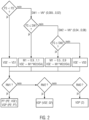
- ein schematisches Ablaufdiagramm des Verfahrens.
- Wie die
Figur 1 erkennen lässt, umfasst die Abfüllanlage 1 zum Sterilisieren und Puffern eines flüssigen Produkts 2 sowie zu dessen Abfüllung in Flaschen 3, Dosen oder vergleichbare Behälter eine Kurzzeiterhitzungseinheit 4 zur prinzipiell bekannten Durchlauferhitzung/ -heißhaltung des Produkts 2, einen nachgeschalteten Puffertank 5 für das derart sterilisierte Produkt 2 und einen wiederum nachgeschalteten Füller 6 zum Abfüllen des Produkts 2. - Der Puffertank 5 umfasst einen prinzipiell bekannten Füllstandwächter 7 und eine erste elektronische Regeleinrichtung 8 zur füllstandabhängigen Anpassung eines eingangsseitigen Volumenstroms VSE des Produkts 2 in den Puffertank 5, was nachfolgend der Übersichtlichkeit halber auch als Füllstandregelung bezeichnet wird. Darunter ist zu verstehen, dass der eingangsseitige Volumenstrom VSE angepasst wird, um den Ist-Füllstand FS des Produkts 2 möglichst an einen vorzugsweise sortenspezifisch vorgegebenen Soll-Füllstand FS` im Puffertank 5 anzugleichen.
- Ferner ist ein erster Durchflusswächter 9 zur Ermittlung eines ausgangsseitigen Volumenstroms VSA des Produkts 2 aus dem Puffertank 5 vorhanden.
- Die erste Regeleinrichtung 8 ist derart ausgebildet und programmiert, dass der eingangsseitige Volumenstrom VSE innerhalb eines vorgegebenen Arbeitsbereichs AB des Ist-Füllstands FS des Produkts 2 auch in Abhängigkeit vom ausgangsseitigen Volumenstrom VSA verändert werden kann. Zu diesem Zweck kann in der ersten Regeleinrichtung 8 ein Sollwert VSE' des eingangsseitigen Volumenstroms VSE in Abhängigkeit vom Ist-Füllstand FS und vom ausgangsseitigen Volumenstroms VSA berechnet werden.
- Die Kurzzeiterhitzungseinheit 4 umfasst eine zweite elektronische Regeleinrichtung 10 zur Durchflussregelung und/oder Temperaturregelung der Durchlauferhitzung/ -heißhaltung des Produkts 2. Hierzu kann die zweite Regeleinrichtung 10 auf der Grundlage des Sollwerts VSE' des eingangsseitigen Volumenstroms VSE eine Soll-Pasteurisierungstemperatur PT' und/oder einen Soll-Pasteurisierungsvolumenstrom VSP` des Produkts 2 berechnen oder einen sortenabhängigen Soll-Pasteurisierungsvolumenstrom VSP' insbesondere auch unabhängig von der Pufferung des Produkts 2 vorgeben, wie nachfolgend noch für drei grundlegende Regelungsmodi RM1, RM2, RM3 der zweiten Regeleinrichtung 10 beschrieben wird.
- Die zweite Regeleinrichtung 10 ist demnach derart ausgebildet und programmiert, dass sie den Soll-Pasteurisierungsvolumenstrom VSP' entweder bei vorgegebenem Soll-Pasteurisierungsgrad PE` oder vorgegebener Soll-Pasteurisierungstemperatur PT' des Produkts 2 mithilfe des Sollwerts VSE' des eingangsseitigen Volumenstroms VSE berechnet oder davon unabhängig bei vorgegebener Soll-Pasteurisierungsdauer PD` sortenspezifisch einstellt.
- Der erste Durchflusswächter 9 zur Ermittlung des ausgangsseitigen Volumenstroms VSA umfasst vorzugsweise einen zwischen dem Puffertank 5 und dem Füller 6 angeordneten Durchflussmesser 9a und eine zugehörige Auswerteeinheit 9b, die beispielsweise zur zeitlichen Mittelung des gemessenen ausgangsseitigen Volumenstroms VSA ausgebildet ist.
- Dargestellt ist ferner ein zweiter Durchflusswächter 11 zur Ermittlung des eingangsseitigen Volumenstroms VSE, der auf prinzipiell gleiche Weise arbeiten und alternativ (anstelle des ersten Durchflusswächters 9) in Kombination mit dem Füllstandwächter 7 dazu eingesetzt werden kann, den ausgangsseitigen Volumenstrom VSA aus dem jeweils überwachten eingangsseitigen Volumenstrom VSE und Ist-Füllstand FS zu berechnen.
- Dargestellt ist in der
Figur 1 ferner ein Soll-Füllstand FS`, der beispielsweise sortenspezifisch je nach Produkt 2 und/oder Typ der Flaschen 3 in der ersten Regeleinrichtung 8 vorgegeben werden kann. Es wird dann beispielsweise mit Hilfe des Füllstandwächters 7 gemessen und ausgewertet, um wieviel der Ist-Füllstands FS vom jeweiligen Sollfüllstands FS' abweicht. In Abhängigkeit von der festgestellten Abweichung kann dann in der ersten Regeleinrichtung 8 ein Multiplikator M1 ausgewählt werden, der zur Berechnung des Sollwerts VSE' des eingangsseitigen Volumenstroms VSE dient. - In die Berechnung des Sollwerts VSE' geht dann ferner ein Multiplikand M2 ein, der durch zeitliche Mittelung des gemessenen ausgangsseitigen Volumenstroms VSA insbesondere durch gleitende Mittelwertbildung berechnet wird. Die Mittelung erfolgt dann beispielsweise über einen Zeitraum von 10 bis 200 s, insbesondere von 30 bis 100 s. Dadurch lassen sich ausgangsseitige Schwankungen durch unterschiedliche Abnahme des Produkts 2 im Bereich des Füllers 6 berücksichtigen bzw. kompensierend glätten.
- Im einfachsten Fall ergibt sich der Sollwert VSE' des eingangsseitigen Volumenstroms VSE aus der Multiplikation M1 * M2. Das heißt, der Sollwert VSE' wird in Relation zum insbesondere zeitlich gemittelten ausgangsseitigen Volumenstrom VSA festgelegt und kann von der zweiten Regeleinrichtung 10 der Kurzzeiterhitzungseinheit 4 für deren Temperaturregelung und/oder Durchflussregelung übernommen werden, also zur Berechnung der Soll-Pasteurisierungstemperatur PT` und/oder des Soll-Pasteurisierungsvolumenstroms VSP`.
- Der Multiplikator M1 kann je nach Ist-Füllstand FS unterschiedliche Werte annehmen. Der Multiplikator M1 beträgt beispielsweise 0,9 bis 1,1, bevorzugt 1, wenn der Ist-Füllstand FS so groß ist wie der Soll-Füllstand FS' oder diesen bis zu einem ersten Schwellenwert SW1 übersteigt. Zudem kann der Multiplikator M1 0,5 bis 0,9, bevorzugt das 0,75 bis 0,85-Fache betragen, wenn der Ist-Füllstand FS den Soll-Füllstand FS' um wenigstens den ersten Schwellenwert SW1 und höchsten um einen zweiten (höheren) Schwellenwert SW2 übersteigt.
- Die Schwellenwerte SW1, SW2 werden vorzugsweise relativ zu einem Nennvolumen VN des Puffertanks 5 festgelegt. Der erste Schwellenwert SW1 beträgt beispielsweise 0,5 bis 2% des Nennvolumens VN des Puffertanks 5, der zweite Schwellenwert SW2 beträgt beispielsweise 4 bis 8% des Nennvolumens VN.
- Entsprechende absolute Füllstandschwellenwerte ergeben sich somit aus der Addition des jeweiligen Soll-Füllstands FS' und der wie oben definierten Schwellenwerte SW1, SW2. In Analogie dazu könnten auch weitere derartige Schwellenwerte verwendet werden oder nur einer der Schwellenwerte SW1, SW2.
- Wie die
Figur 1 ferner schematisch erkennen lässt, erstreckt sich der Arbeitsbereich AB vorzugsweise zwischen dem jeweiligen Soll-Füllstand FS' und dem jeweils größten Schwellenwert, im gezeigten Beispiel dem zweiten Schwellenwert SW2. - Außerhalb des Arbeitsbereichs AB kann der Sollwert VSE' des eingangsseitigen Volumenstroms VSE unabhängig vom ausgangsseitigen Volumenstrom VSA festgelegt werden.
- Liegt der Ist-Füllstand FS beispielsweise oberhalb des zweiten Schwellenwerts SW2, so wird vorzugsweise ein vorgegebener Mindestvolumenstrom VS0 der Durchlauferhitzung/ -heißhaltung als Sollwert VSE' des eingangsseitigen Volumenstroms VSE ausgewählt.
- Liegt der Ist-Füllstand FS unterhalb des Soll-Füllstands FS`, wird vorzugsweise ein Nennvolumenstrom VS1 der Durchlauferhitzung/ -heißhaltung als Sollwert VSE' des eingangsseitigen Volumenstroms VSE ausgewählt.
- In der zweiten Regeleinrichtung 10 der Kurzzeiterhitzungseinheit 4 ist vorzugsweise ferner ein Maximalvolumenstrom VS2 der Durchlauferhitzung/ -heißhaltung gespeichert, über den der Soll-Pasteurisierungsvolumenstrom VSP' regelungsbedingt nicht ansteigen kann.
- Die zweite Regeleinrichtung 10 ermöglicht vorzugsweise drei unterschiedliche Regelungsmodi RM1, RM2, RM3 (siehe
Figur 2 ) für die Kurzzeiterhitzungseinheit 4, nämlich einen ersten Regelungsmodus RM1 zur Einhaltung eines festgelegten Soll-Pasteurisierungsgrads PE`, einen zweiten Regelungsmodus RM2 zur Einhaltung einer festgelegten Soll-Pasteurisierungstemperatur PT' und/oder einen dritten Regelungsmodus RM3 zur Einhaltung einer festgelegten Soll-Pasteurisierungsdauer PD`. - Beim ersten Regelungsmodus RM1 mit einer Regelung auf Soll-Pasteurisierungsgrad PE` wird zunächst der in der ersten Regeleinrichtung 8 des Puffertanks 5 berechnete Sollwerts VSE' des eingangsseitigen Volumenstroms VSE übernommen.
- Die zweite Regeleinrichtung 10 errechnet daraus eine zum Soll-Pasteurisierungsgrad PE` passende Soll-Pasteurisierungstemperatur PT` zur Temperaturregelegung der Kurzzeiterhitzungseinheit 4.
- Aus einer im Bereich der Kurzzeiterhitzungseinheit 4 auf prinzipiell bekannte Weise gemessenen Ist-Pasteurisierungstemperatur PT wird dann ein dazu passender Volumenstrom berechnet, mit dem wenigstens der geforderte Pasteurisierungsgrad PE` erreicht wird, und als Soll-Pasteurisierungsvolumenstrom VSP` zur Durchflussregelung der Kurzzeiterhitzungseinheit 4 verwendet, also zur laufenden Anpassung eines Ist-Pasteurisierungsvolumenstroms VSP durch die Kurzzeiterhitzungseinheit 4.
- Die vergleichsweise flinke Durchflussregelung ermöglicht eine laufende und präzise Anpassung des Ist-Pasteurisierungsvolumenstroms VSP zum Einhalten des Soll-Pasteurisierungsgrads PE` je nach herrschender Ist-Pasteurisierungstemperatur PT.
- Im Anschluss kann die Soll-Pasteurisierungstemperatur PT' laufend an die Erfordernisse im Bereich des Puffertanks 5, also in Abhängigkeit vom Sollwert VSE' des eingangsseitigen Volumenstroms VSE angepasst werden.
- Das heißt, die Temperaturregelung der Kurzzeiterhitzungseinheit 4 folgt der Füllstandsregelung der ersten Regeleinrichtung 8, die Durchflussregelung der Kurzzeiterhitzungseinheit 4 folgt ihrer Temperaturregelung.
- Hierbei wird der Ist-Pasteurisierungsgrad PE des Produkts 2 mittels Durchflussregelung vergleichsweise flink an den jeweiligen Soll-Pasteurisierungsgrad PE' des Produkts 2 angepasst und somit die Behandlungsqualität hergestellt.
- Dies ermöglicht eine zuverlässig ordnungsgemäße Sterilisierung des Produkts 2 und eine effektive Ausnutzung des Puffertanks 5, um stets einen möglichst großen Anteil seines Nennvolumens VN zur Pufferung des Produkts 2 zur Verfügung zu stellen.
- Beim zweiten Regelungsmodus RM2 der Kurzzeiterhitzungseinheit 4 mit fest vorgegebener Soll-Pasteurisierungstemperatur PT' wird der Sollwert VSE' des eingangsseitigen Volumenstroms VSE über eine insbesondere sortenspezifische Glättungsfunktion GF in den Soll-Pasteurisierungsvolumenstrom VSP' überführt. Das heißt, vergleichsweise kurzfristige Schwankungen des Sollwerts VSE' wirken sich nur abgeschwächt und zeitlich versetzt auf den Soll-Pasteurisierungsvolumenstrom VSP' aus, um ein zu flinkes Reagieren der Durchflussregelung der Kurzzeiterhitzungseinheit 4 im Vergleich zu deren trägerer Temperaturregelung zu vermeiden.
- Zu diesem Zweck umfasst die Glättungsfunktion GF vorzugsweise eine maximale relative Flankensteilheit, also eine maximale relative Änderung des Soll-Pasteurisierungsvolumenstroms VSP` pro Zeiteinheit. Beispielsweise beträgt die relative Flankensteilheit der Glättungsfunktion GF maximal 0,5 % des Nennvolumenstroms VS1 der Durchlauferhitzung/ -heißhaltung und insbesondere maximal 0,3 % davon. Dadurch lässt sich vor allem vermeiden, dass im zweiten Regelungsmodus RM2 ein geforderter minimaler Soll-Pasteurisierungsgrad PE` durch zu schnelles Absenken (Nachführen) des Soll-Pasteurisierungsvolumenstroms VSP' unterschritten wird.
- Im dritten Regelungsmodus RM3 mit fest vorgegebener Soll-Pasteurisierungsdauer PD' wird der Soll-Pasteurisierungsvolumenstrom VSP' sortenspezifisch, also abhängig vom Produkt 2 von der zweite Regeleinrichtung 10 der Kurzzeiterhitzungseinheit 4 ausgewählt und dann vorzugsweise nicht an den Sollwert VSE' des eingangsseitigen Volumenstroms VSE angepasst.
- Die oben genannten Regelungsmodi RM1, RM2, RM3 könnten für unterschiedliche Produkte 2 und/oder Betriebssituationen wahlweise aktiviert werden.
- Grundlagen der voranstehend beschriebenen Füllstandregelung für den Puffertank 5 und der Temperatur- sowie Durchflussregelung für die Kurzzeiterhitzungseinheit 4 sind zum besseren Verständnis zusätzlich anhand der
Fig. 2 schematisch und beispielhaft als Ablaufdiagramm unter Verwendung entsprechender Bezugszeichen erläutert. Einige Größen sind als Funktion dahinter in Klammern gesetzter Parameter oder Wertebereiche angegeben. - Bei den beschriebenen Regelungsvarianten wird jeweils vorausgesetzt, dass die Produktleitungen der Kurzzeiterhitzungseinheit 4 und die Verbindungsleitung zum Puffertank 5 vollständig mit dem Produkt 2 gefüllt sind und dieses auf prinzipiell bekannte Weise in den Puffertank 5 gepumpt wird.
- Die Kurzeiterhitzungseinheit 4 ist entsprechend für einen kontinuierlichen Durchstrom des Produkts 2 im Sterilisierungsbetrieb ausgebildet.
- Der erste Regelungsmodus RM1 zur Regelung auf einen Soll-Pasteurisierungsgrad PE' ist besonders flexibel einsetzbar zugunsten einer möglichst genauen Einhaltung der geforderten Produktqualität und einer effizienten Ausnutzung des Puffertanks 5 im Sinne einer maximierten Pufferzeit für den Fall einer reduzierten oder unterbrochenen Abnahme des Produkts 2 durch den Füller 6. Je nach Produkt 2 und/oder bestimmten Betriebssituationen kann der zweite oder dritte Regelungsmodus RM2, RM3 gezielt eingesetzt werden.
- Die beschriebene Füllstandregelung für den Puffertank 5 unter zusätzlicher Berücksichtigung des ausgangsseitigen Volumenstroms VSA innerhalb des Arbeitsbereichs AB ermöglicht eine besonders exakte Anpassung des Ist-Füllstands FS während des regulären Abfüllbetriebs, so dass bei einer gegebenenfalls reduzierten Produktabnahme durch den Füller 6 stets ein möglichst großes Restvolumen des Puffertanks 5 für eine anschließende Pufferung des aus der Kurzzeiterhitzungseinheit 4 nachgelieferten Produkts 2 zur Verfügung steht. Dies dient auch einem möglichst konstanten Betrieb der vorgeschalteten Kurzzeiterhitzungseinheit 4.
- Bei Erreichen eines maximalen Füllstands des Produkts 2 im Puffertank 5, wäre das Produkt 2 beispielsweise auf an sich bekannte Weise vor/aus dem Puffertank 5 in einen Rückführkreislauf abzuzweigen.
- Aufgrund der beschriebenen Regelungsmodi RM1, RM2, RM3 der Kurzzeiterhitzungseinheit 4 und der beschriebenen Füllstandregelung am Puffertank 5 lassen sich unterschiedliche Produkte 2 mit den erforderlichen Pasteurisierungseinheiten unter Maximierung der Pufferkapazität des Puffertanks 5 behandeln.
Claims (15)
- Verfahren zum Puffern eines mittels Durchlauferhitzung/ -heißhaltung in einer Kurzzeiterhitzungseinheit (4) sterilisierten Produkts (2) in einem dieser nachgeschalteten Puffertank (5) vor Abfüllung des Produkts in Flaschen (3), Dosen oder dergleichen Behälter in einem dem Puffertank nachgeschalteten Füller (6), wobei ein Ist-Füllstand (FS) des Produkts im Puffertank überwacht und ein eingangsseitiger Volumenstrom (VSE) des Produkts in den Puffertank in Abhängigkeit vom Ist-Füllstand geregelt wird, wobei in einer programmierten Regeleinheit (8) ein ausgangsseitiger Volumenstrom (VSA) des Produkts aus dem Puffertank überwacht und der eingangsseitige Volumenstrom innerhalb wenigstens eines vorgegebenen Arbeitsbereichs (AB) des Ist-Füllstands ferner in Abhängigkeit vom ausgangsseitigen Volumenstrom geregelt und hierfür ein Sollwert (VSE`) des eingangsseitigen Volumenstroms in Abhängigkeit vom Ist-Füllstand (FS) und vom ausgangsseitigen Volumenstrom (VSA) berechnet wird, und dass aus dem Sollwert (VSE`) des eingangsseitigen Volumenstroms (VSE) und einem Soll-Pasteurisierungsgrad (PE`) eine Soll-Pasteurisierungstemperatur (PT`) zur Temperaturregelung der Durchlauferhitzung/ -heißhaltung berechnet wird, wobei in Abhängigkeit von einer im Bereich der Durchlauferhitzung/ -heißhaltung herrschenden Ist-Pasteurisierungstemperatur (PT) ein zum Erreichen des Soll-Pasteurisierungsgrads (PE`) erforderlicher Soll-Pasteurisierungsvolumenstrom (VSP`) zur Durchflussregelung der Durchlauferhitzung/ -heißhaltung berechnet wird.
- Verfahren nach Anspruch 1, wobei eine Abweichung des Ist-Füllstands (FS) von einem insbesondere produktspezifisch vorgegebenen Soll-Füllstand (FS`) ermittelt wird und abhängig von der Abweichung ein Multiplikator (M1) zur Berechnung eines Sollwerts (VSE`) des eingangsseitigen Volumenstroms (VSE) ausgewählt wird.
- Verfahren nach Anspruch 2, wobei der ausgangseitige Volumenstrom (VSA) durch Mittelung über einen Zeitraum von 10 s bis 200 s, insbesondere 30 s bis 100 s, berechnet wird und als Multiplikand (M2) in die Berechnung des Sollwerts (VSE`) des eingangsseitigen Volumenstroms (VSE) eingeht.
- Verfahren nach Anspruch 2 oder 3, wobei das 0,9-Fache bis 1,1-Fache, insbesondere das 1-Fache des ausgangsseitigen Volumenstroms (VSA) als Sollwert (VSE`) des eingangsseitigen Volumenstroms (VSE) vorgegeben wird, wenn der Ist-Füllstand (FS) so groß ist wie der Soll-Füllstand (FS`) oder diesen bis zu einem ersten Schwellenwert (SW1) übersteigt, und wobei das 0,5-Fache bis 0,9-Fache, insbesondere das 0,75-Fache bis 0,85-Fache des ausgangsseitigen Volumenstroms als Sollwert des eingangsseitigen Volumenstroms vorgegeben wird, wenn der Ist-Füllstand den Soll-Füllstand um wenigstens den ersten Schwellenwert und höchstens um einen zweiten Schwellenwert (SW2) übersteigt.
- Verfahren nach Anspruch 4, wobei ein Mindestvolumenstrom (VS0) der Durchlauferhitzung / -heißhaltung vorgegeben ist und maschinell als Sollwert (VSE`) des eingangsseitigen Volumenstroms (VSE) ausgewählt wird, wenn der Ist-Füllstand (FS) den Soll-Füllstand (FS`) um mehr als den zweiten Schwellenwert (SW2) übersteigt.
- Verfahren nach Anspruch 4 oder 5, wobei der erste Schwellenwert (SW1) 0,5 bis 2% des Nennvolumens (NV) des Puffertanks (5) beträgt, und/oder wobei der zweite Schwellenwert (SW2) 4 bis 8% des Nennvolumens des Puffertanks beträgt.
- Verfahren nach einem der Ansprüche 2 bis 6, wobei ein Nennvolumenstrom (VS1) der Durchlauferhitzung/ -heißhaltung vorgegeben ist und maschinell als Sollwert (VSE`) des eingangsseitigen Volumenstroms (VSE) ausgewählt wird, wenn der Ist-Füllstand (FS) kleiner ist als der Soll-Füllstand (FS`).
- Verfahren nach wenigstens einem der Ansprüche 1 bis 7, wobei der Soll-Pasteurisierungsgrad (PE`) sortenspezifisch vorgegeben wird.
- Verfahren nach wenigstens einem der Ansprüche 2 bis 7, wobei ein Soll-Pasteurisierungsvolumenstrom (VSP`) der Durchlauferhitzung/ -heißhaltung unter Vorgabe einer Soll-Pasteurisierungstemperatur (PT') an den Sollwert des eingangsseitigen Volumenstroms (VSE`) mittels einer insbesondere sortenspezifischen Glättungsfunktion (GF) angeglichen wird.
- Verfahren nach Anspruch 9, wobei die Glättungsfunktion (GF) ein zeitliches Regelverhalten zur Temperaturregelung der Durchlauferhitzung /-heißhaltung nachbildet, insbesondere mit einer maximalen relativen Flankensteilheit von 0,5% pro Sekunde, und insbesondere 0,3% pro Sekunde, bezogen auf einen Nennvolumenstrom (VS1) der Durchlauferhitzung / -heißhaltung.
- Verfahren nach wenigstens einem der Ansprüche 2 bis 7, wobei ein Soll-Pasteurisierungsvolumenstrom (VSP`) der Durchlauferhitzung / -heißhaltung unter Vorgabe einer Soll-Pasteurisierungsdauer (PD`) unabhängig vom Sollwert des eingangsseitigen Volumenstroms (VSE`) sortenspezifisch vorgegeben wird.
- Abfüllanlage (1) umfassend: eine Kurzzeiterhitzungseinheit (4) zur Sterilisierung eines Produkts (2) im Durchlauf; einen Füller (6) zur Abfüllung des Produkts in Flaschen (3), Dosen oder dergleichen Behälter; und einen zwischengeschalteten Puffertank (5) mit einem Füllstandwächter (7) und einer ersten Regeleinrichtung (8) zur füllstandabhängigen Anpassung eines eingangsseitigen Volumenstroms (VSE) des Produkts in den Puffertank, wobei eine Einrichtung zur Ermittlung eines ausgangsseitigen Volumenstroms (VSA) des Produkts aus dem Puffertank vorhanden ist und die erste Regeleinrichtung ferner dazu ausgebildet ist, den eingangsseitigen Volumenstrom (VSE) innerhalb wenigstens eines vorgegebenen Arbeitsbereichs (AB) des Ist-Füllstands (FS) des Produkts in Abhängigkeit vom ausgangsseitigen Volumenstrom (VSA) gemäß dem Verfahren nach wenigstens einem der vorigen Ansprüche zu regeln und hierfür einen Sollwert (VSE`) des eingangsseitigen Volumenstroms (VSE) in Abhängigkeit vom Ist-Füllstand (FS) und vom ausgangsseitigen Volumenstrom (VSA) zu berechnen, wobei die Kurzzeiterhitzungseinheit (4) eine zweite Regeleinrichtung (10) zur Durchflussregelung der Sterilisierung umfasst, um den berechneten Sollwert (VSE`) des eingangsseitigen Volumenstroms (VSE) insbesondere mittels einer zeitlichen Glättungsfunktion (GF) zu übernehmen und daraus einen Soll-Pasteurisierungsvolumenstrom (VSP`) des Produkts (2) in der Kurzzeiterhitzungseinheit zu berechnen.
- Abfüllanlage nach Anspruch 12, wobei die zweite Regeleinrichtung (10) ferner zur Temperaturregelung der Sterilisierung ausgebildet ist, um den berechneten Sollwert (VSE`) des eingangsseitigen Volumenstroms (VSE) insbesondere mittels einer zeitlichen Glättungsfunktion (GF) zu übernehmen und daraus eine Soll-Pasteurisierungstemperatur (PT') des Produkts (2) in der Kurzzeiterhitzungseinheit zu berechnen.
- Abfüllanlage nach Anspruch 12 oder 13, wobei die Einrichtung zur Ermittlung des ausgangsseitigen Volumenstroms ein Durchflusswächter (9) mit einem zwischen dem Puffertank (5) und dem Füller (6) angeordneten Durchflussmesser (9a) ist.
- Abfüllanlage nach wenigstens einem der Ansprüche 12 bis 14, wobei der Puffertank (5) ein Nennvolumen von 5 bis 30 m3 aufweist.
Applications Claiming Priority (1)
| Application Number | Priority Date | Filing Date | Title |
|---|---|---|---|
| DE102021100003.3A DE102021100003A1 (de) | 2021-01-04 | 2021-01-04 | Verfahren zum Puffern eines sterilisierten flüssigen Produkts und Abfüllanlage |
Publications (2)
| Publication Number | Publication Date |
|---|---|
| EP4024156A1 EP4024156A1 (de) | 2022-07-06 |
| EP4024156B1 true EP4024156B1 (de) | 2024-04-03 |
Family
ID=79025081
Family Applications (1)
| Application Number | Title | Priority Date | Filing Date |
|---|---|---|---|
| EP21211639.6A Active EP4024156B1 (de) | 2021-01-04 | 2021-12-01 | Verfahren zum puffern eines sterilisierten flüssigen produkts und abfüllanlage |
Country Status (4)
| Country | Link |
|---|---|
| EP (1) | EP4024156B1 (de) |
| CN (1) | CN217479034U (de) |
| DE (1) | DE102021100003A1 (de) |
| DK (1) | DK4024156T3 (de) |
Family Cites Families (5)
| Publication number | Priority date | Publication date | Assignee | Title |
|---|---|---|---|---|
| JPS6175907A (ja) * | 1984-09-21 | 1986-04-18 | Ebara Corp | 水位制御装置 |
| JPH0910286A (ja) | 1995-06-27 | 1997-01-14 | Mitsubishi Heavy Ind Ltd | 製品液過熱殺菌装置および方法 |
| SE508884C2 (sv) * | 1997-02-27 | 1998-11-16 | Tetra Laval Holdings & Finance | Metod att reglera nivån i en bufferttank |
| PH12012502184A1 (en) * | 2010-05-20 | 2021-06-23 | Miteco Ag | System and method for pasteurizing at least one liquid |
| CN108100375A (zh) | 2012-09-24 | 2018-06-01 | 雀巢产品技术援助有限公司 | 用于协调无菌灭菌与无菌包装填充速率的方法和系统 |
-
2021
- 2021-01-04 DE DE102021100003.3A patent/DE102021100003A1/de active Pending
- 2021-12-01 EP EP21211639.6A patent/EP4024156B1/de active Active
- 2021-12-01 DK DK21211639.6T patent/DK4024156T3/da active
- 2021-12-30 CN CN202123430758.3U patent/CN217479034U/zh active Active
Also Published As
| Publication number | Publication date |
|---|---|
| DK4024156T3 (da) | 2024-04-22 |
| CN217479034U (zh) | 2022-09-23 |
| DE102021100003A1 (de) | 2022-07-07 |
| EP4024156A1 (de) | 2022-07-06 |
Similar Documents
| Publication | Publication Date | Title |
|---|---|---|
| DE102011011545B4 (de) | Verfahren und Vorrichtung zum Einbringen eines Fluids in eine Fuge | |
| EP2481713B1 (de) | Verfahren zum Betrieb einer Wasserenthärtungsanlage und Wasserenthärtungsanlage zur Durchführung des Verfahrens | |
| EP2571372B1 (de) | Anlage und verfahren zur pasteurisierung mindestens einer flüssigkeit | |
| WO2016116277A1 (de) | Regelung des strahlmitteldurchsatzes einer strahlanlage | |
| EP2468155B1 (de) | Verfahren zur Regelung der Heißwasserzubereitung | |
| EP4714623A2 (de) | Vorrichtung und verfahren zur überwachung und/oder regelung eines schmierzustandes in einer kontinuierlich arbeitenden presse | |
| EP2913594A1 (de) | Verfahren zum Betreiben einer pufferspeicherlosen Heizungsanlage, insbesondere zur Gewährleistung eines sicheren und einwandfreien Betriebs | |
| EP3995275A1 (de) | Haftmittelauftragsvorrichtung, kantenanleimmaschine und verfahren zum betrieb einer solchen | |
| EP3215742A1 (de) | Verfahren und vorrichtung zum betreiben einer pumpe | |
| EP2956250A1 (de) | Kühlstrecke mit power cooling und laminarkühlung | |
| EP2651467B1 (de) | Extrakorporale blutbehandlungsvorrichtung | |
| EP3623068B1 (de) | Aufbringeinrichtungen von kühlstrecken mit zweitem anschluss | |
| EP3524577A1 (de) | Wasserenthärtungsanlage mit bestimmung einer regeneriermittelkonzentration über eine förderdauer und ein fördervolumen oder eine fördermasse | |
| DE102021100003A1 (de) | Verfahren zum Puffern eines sterilisierten flüssigen Produkts und Abfüllanlage | |
| EP2783716B1 (de) | Verfahren und Vorrichtung zur Erkennung einer Rezirkulation in einem Shunt | |
| DE102006038652A1 (de) | Verfahren zur Tankdruckregelung für ein Abfüllen eines Produkts | |
| EP2507102B1 (de) | Verfahren zur ansteuerung eines umschaltventils in einem hydraulischen kfz-bremssystem | |
| EP2409580B1 (de) | Verfahren und Vorrichtung zur Medienführung durch eine thermische Behandlungsanlage für ein flüssiges Produkt | |
| EP1173295A1 (de) | Walzverfahren für ein metallband und hiermit korrespondierende walzanordnung | |
| EP1454540B1 (de) | Vorrichtung und Verfahren zur Pasteurisierung von Produkten | |
| DE102010009753A1 (de) | Vorrichtung und Verfahren zur Dosierregelung von Schüttgut | |
| EP4255662B1 (de) | Verfahren zur limitierung einer schweissleistung eines schweissgeräts | |
| EP3765216B1 (de) | Kühlgruppe für eine laminarkühlvorrichtung | |
| EP4257991B1 (de) | Aktives erdungssystem mit vorausschauender überwachung | |
| EP1781452A1 (de) | Verfahren und vorrichtung zur minimierung des giveaways |
Legal Events
| Date | Code | Title | Description |
|---|---|---|---|
| PUAI | Public reference made under article 153(3) epc to a published international application that has entered the european phase |
Free format text: ORIGINAL CODE: 0009012 |
|
| STAA | Information on the status of an ep patent application or granted ep patent |
Free format text: STATUS: THE APPLICATION HAS BEEN PUBLISHED |
|
| AK | Designated contracting states |
Kind code of ref document: A1 Designated state(s): AL AT BE BG CH CY CZ DE DK EE ES FI FR GB GR HR HU IE IS IT LI LT LU LV MC MK MT NL NO PL PT RO RS SE SI SK SM TR |
|
| STAA | Information on the status of an ep patent application or granted ep patent |
Free format text: STATUS: REQUEST FOR EXAMINATION WAS MADE |
|
| 17P | Request for examination filed |
Effective date: 20230109 |
|
| RBV | Designated contracting states (corrected) |
Designated state(s): AL AT BE BG CH CY CZ DE DK EE ES FI FR GB GR HR HU IE IS IT LI LT LU LV MC MK MT NL NO PL PT RO RS SE SI SK SM TR |
|
| P01 | Opt-out of the competence of the unified patent court (upc) registered |
Effective date: 20230523 |
|
| GRAP | Despatch of communication of intention to grant a patent |
Free format text: ORIGINAL CODE: EPIDOSNIGR1 |
|
| STAA | Information on the status of an ep patent application or granted ep patent |
Free format text: STATUS: GRANT OF PATENT IS INTENDED |
|
| INTG | Intention to grant announced |
Effective date: 20231020 |
|
| GRAS | Grant fee paid |
Free format text: ORIGINAL CODE: EPIDOSNIGR3 |
|
| GRAA | (expected) grant |
Free format text: ORIGINAL CODE: 0009210 |
|
| STAA | Information on the status of an ep patent application or granted ep patent |
Free format text: STATUS: THE PATENT HAS BEEN GRANTED |
|
| AK | Designated contracting states |
Kind code of ref document: B1 Designated state(s): AL AT BE BG CH CY CZ DE DK EE ES FI FR GB GR HR HU IE IS IT LI LT LU LV MC MK MT NL NO PL PT RO RS SE SI SK SM TR |
|
| REG | Reference to a national code |
Ref country code: CH Ref legal event code: EP |
|
| REG | Reference to a national code |
Ref country code: DK Ref legal event code: T3 Effective date: 20240418 |
|
| REG | Reference to a national code |
Ref country code: IE Ref legal event code: FG4D Free format text: LANGUAGE OF EP DOCUMENT: GERMAN |
|
| REG | Reference to a national code |
Ref country code: DE Ref legal event code: R096 Ref document number: 502021003193 Country of ref document: DE |
|
| REG | Reference to a national code |
Ref country code: SE Ref legal event code: TRGR |
|
| REG | Reference to a national code |
Ref country code: LT Ref legal event code: MG9D |
|
| REG | Reference to a national code |
Ref country code: NL Ref legal event code: MP Effective date: 20240403 |
|
| PG25 | Lapsed in a contracting state [announced via postgrant information from national office to epo] |
Ref country code: NL Free format text: LAPSE BECAUSE OF FAILURE TO SUBMIT A TRANSLATION OF THE DESCRIPTION OR TO PAY THE FEE WITHIN THE PRESCRIBED TIME-LIMIT Effective date: 20240403 |
|
| PG25 | Lapsed in a contracting state [announced via postgrant information from national office to epo] |
Ref country code: NL Free format text: LAPSE BECAUSE OF FAILURE TO SUBMIT A TRANSLATION OF THE DESCRIPTION OR TO PAY THE FEE WITHIN THE PRESCRIBED TIME-LIMIT Effective date: 20240403 |
|
| PG25 | Lapsed in a contracting state [announced via postgrant information from national office to epo] |
Ref country code: IS Free format text: LAPSE BECAUSE OF FAILURE TO SUBMIT A TRANSLATION OF THE DESCRIPTION OR TO PAY THE FEE WITHIN THE PRESCRIBED TIME-LIMIT Effective date: 20240803 |
|
| PG25 | Lapsed in a contracting state [announced via postgrant information from national office to epo] |
Ref country code: BG Free format text: LAPSE BECAUSE OF FAILURE TO SUBMIT A TRANSLATION OF THE DESCRIPTION OR TO PAY THE FEE WITHIN THE PRESCRIBED TIME-LIMIT Effective date: 20240403 |
|
| PG25 | Lapsed in a contracting state [announced via postgrant information from national office to epo] |
Ref country code: HR Free format text: LAPSE BECAUSE OF FAILURE TO SUBMIT A TRANSLATION OF THE DESCRIPTION OR TO PAY THE FEE WITHIN THE PRESCRIBED TIME-LIMIT Effective date: 20240403 Ref country code: FI Free format text: LAPSE BECAUSE OF FAILURE TO SUBMIT A TRANSLATION OF THE DESCRIPTION OR TO PAY THE FEE WITHIN THE PRESCRIBED TIME-LIMIT Effective date: 20240403 |
|
| PG25 | Lapsed in a contracting state [announced via postgrant information from national office to epo] |
Ref country code: GR Free format text: LAPSE BECAUSE OF FAILURE TO SUBMIT A TRANSLATION OF THE DESCRIPTION OR TO PAY THE FEE WITHIN THE PRESCRIBED TIME-LIMIT Effective date: 20240704 |
|
| PG25 | Lapsed in a contracting state [announced via postgrant information from national office to epo] |
Ref country code: PT Free format text: LAPSE BECAUSE OF FAILURE TO SUBMIT A TRANSLATION OF THE DESCRIPTION OR TO PAY THE FEE WITHIN THE PRESCRIBED TIME-LIMIT Effective date: 20240805 |
|
| PG25 | Lapsed in a contracting state [announced via postgrant information from national office to epo] |
Ref country code: ES Free format text: LAPSE BECAUSE OF FAILURE TO SUBMIT A TRANSLATION OF THE DESCRIPTION OR TO PAY THE FEE WITHIN THE PRESCRIBED TIME-LIMIT Effective date: 20240403 |
|
| PG25 | Lapsed in a contracting state [announced via postgrant information from national office to epo] |
Ref country code: CZ Free format text: LAPSE BECAUSE OF FAILURE TO SUBMIT A TRANSLATION OF THE DESCRIPTION OR TO PAY THE FEE WITHIN THE PRESCRIBED TIME-LIMIT Effective date: 20240403 |
|
| PG25 | Lapsed in a contracting state [announced via postgrant information from national office to epo] |
Ref country code: PL Free format text: LAPSE BECAUSE OF FAILURE TO SUBMIT A TRANSLATION OF THE DESCRIPTION OR TO PAY THE FEE WITHIN THE PRESCRIBED TIME-LIMIT Effective date: 20240403 |
|
| PG25 | Lapsed in a contracting state [announced via postgrant information from national office to epo] |
Ref country code: LV Free format text: LAPSE BECAUSE OF FAILURE TO SUBMIT A TRANSLATION OF THE DESCRIPTION OR TO PAY THE FEE WITHIN THE PRESCRIBED TIME-LIMIT Effective date: 20240403 |
|
| PG25 | Lapsed in a contracting state [announced via postgrant information from national office to epo] |
Ref country code: PT Free format text: LAPSE BECAUSE OF FAILURE TO SUBMIT A TRANSLATION OF THE DESCRIPTION OR TO PAY THE FEE WITHIN THE PRESCRIBED TIME-LIMIT Effective date: 20240805 Ref country code: PL Free format text: LAPSE BECAUSE OF FAILURE TO SUBMIT A TRANSLATION OF THE DESCRIPTION OR TO PAY THE FEE WITHIN THE PRESCRIBED TIME-LIMIT Effective date: 20240403 Ref country code: NO Free format text: LAPSE BECAUSE OF FAILURE TO SUBMIT A TRANSLATION OF THE DESCRIPTION OR TO PAY THE FEE WITHIN THE PRESCRIBED TIME-LIMIT Effective date: 20240703 Ref country code: LV Free format text: LAPSE BECAUSE OF FAILURE TO SUBMIT A TRANSLATION OF THE DESCRIPTION OR TO PAY THE FEE WITHIN THE PRESCRIBED TIME-LIMIT Effective date: 20240403 Ref country code: IS Free format text: LAPSE BECAUSE OF FAILURE TO SUBMIT A TRANSLATION OF THE DESCRIPTION OR TO PAY THE FEE WITHIN THE PRESCRIBED TIME-LIMIT Effective date: 20240803 Ref country code: HR Free format text: LAPSE BECAUSE OF FAILURE TO SUBMIT A TRANSLATION OF THE DESCRIPTION OR TO PAY THE FEE WITHIN THE PRESCRIBED TIME-LIMIT Effective date: 20240403 Ref country code: GR Free format text: LAPSE BECAUSE OF FAILURE TO SUBMIT A TRANSLATION OF THE DESCRIPTION OR TO PAY THE FEE WITHIN THE PRESCRIBED TIME-LIMIT Effective date: 20240704 Ref country code: FI Free format text: LAPSE BECAUSE OF FAILURE TO SUBMIT A TRANSLATION OF THE DESCRIPTION OR TO PAY THE FEE WITHIN THE PRESCRIBED TIME-LIMIT Effective date: 20240403 Ref country code: ES Free format text: LAPSE BECAUSE OF FAILURE TO SUBMIT A TRANSLATION OF THE DESCRIPTION OR TO PAY THE FEE WITHIN THE PRESCRIBED TIME-LIMIT Effective date: 20240403 Ref country code: CZ Free format text: LAPSE BECAUSE OF FAILURE TO SUBMIT A TRANSLATION OF THE DESCRIPTION OR TO PAY THE FEE WITHIN THE PRESCRIBED TIME-LIMIT Effective date: 20240403 Ref country code: BG Free format text: LAPSE BECAUSE OF FAILURE TO SUBMIT A TRANSLATION OF THE DESCRIPTION OR TO PAY THE FEE WITHIN THE PRESCRIBED TIME-LIMIT Effective date: 20240403 Ref country code: RS Free format text: LAPSE BECAUSE OF FAILURE TO SUBMIT A TRANSLATION OF THE DESCRIPTION OR TO PAY THE FEE WITHIN THE PRESCRIBED TIME-LIMIT Effective date: 20240703 |
|
| REG | Reference to a national code |
Ref country code: DE Ref legal event code: R097 Ref document number: 502021003193 Country of ref document: DE |
|
| PG25 | Lapsed in a contracting state [announced via postgrant information from national office to epo] |
Ref country code: EE Free format text: LAPSE BECAUSE OF FAILURE TO SUBMIT A TRANSLATION OF THE DESCRIPTION OR TO PAY THE FEE WITHIN THE PRESCRIBED TIME-LIMIT Effective date: 20240403 |
|
| PG25 | Lapsed in a contracting state [announced via postgrant information from national office to epo] |
Ref country code: SK Free format text: LAPSE BECAUSE OF FAILURE TO SUBMIT A TRANSLATION OF THE DESCRIPTION OR TO PAY THE FEE WITHIN THE PRESCRIBED TIME-LIMIT Effective date: 20240403 Ref country code: RO Free format text: LAPSE BECAUSE OF FAILURE TO SUBMIT A TRANSLATION OF THE DESCRIPTION OR TO PAY THE FEE WITHIN THE PRESCRIBED TIME-LIMIT Effective date: 20240403 |
|
| PG25 | Lapsed in a contracting state [announced via postgrant information from national office to epo] |
Ref country code: SM Free format text: LAPSE BECAUSE OF FAILURE TO SUBMIT A TRANSLATION OF THE DESCRIPTION OR TO PAY THE FEE WITHIN THE PRESCRIBED TIME-LIMIT Effective date: 20240403 |
|
| PG25 | Lapsed in a contracting state [announced via postgrant information from national office to epo] |
Ref country code: SM Free format text: LAPSE BECAUSE OF FAILURE TO SUBMIT A TRANSLATION OF THE DESCRIPTION OR TO PAY THE FEE WITHIN THE PRESCRIBED TIME-LIMIT Effective date: 20240403 Ref country code: SK Free format text: LAPSE BECAUSE OF FAILURE TO SUBMIT A TRANSLATION OF THE DESCRIPTION OR TO PAY THE FEE WITHIN THE PRESCRIBED TIME-LIMIT Effective date: 20240403 Ref country code: RO Free format text: LAPSE BECAUSE OF FAILURE TO SUBMIT A TRANSLATION OF THE DESCRIPTION OR TO PAY THE FEE WITHIN THE PRESCRIBED TIME-LIMIT Effective date: 20240403 Ref country code: EE Free format text: LAPSE BECAUSE OF FAILURE TO SUBMIT A TRANSLATION OF THE DESCRIPTION OR TO PAY THE FEE WITHIN THE PRESCRIBED TIME-LIMIT Effective date: 20240403 |
|
| PLBE | No opposition filed within time limit |
Free format text: ORIGINAL CODE: 0009261 |
|
| STAA | Information on the status of an ep patent application or granted ep patent |
Free format text: STATUS: NO OPPOSITION FILED WITHIN TIME LIMIT |
|
| 26N | No opposition filed |
Effective date: 20250106 |
|
| PG25 | Lapsed in a contracting state [announced via postgrant information from national office to epo] |
Ref country code: SI Free format text: LAPSE BECAUSE OF FAILURE TO SUBMIT A TRANSLATION OF THE DESCRIPTION OR TO PAY THE FEE WITHIN THE PRESCRIBED TIME-LIMIT Effective date: 20240403 |
|
| PG25 | Lapsed in a contracting state [announced via postgrant information from national office to epo] |
Ref country code: MC Free format text: LAPSE BECAUSE OF FAILURE TO SUBMIT A TRANSLATION OF THE DESCRIPTION OR TO PAY THE FEE WITHIN THE PRESCRIBED TIME-LIMIT Effective date: 20240403 |
|
| REG | Reference to a national code |
Ref country code: CH Ref legal event code: PL |
|
| PG25 | Lapsed in a contracting state [announced via postgrant information from national office to epo] |
Ref country code: LU Free format text: LAPSE BECAUSE OF NON-PAYMENT OF DUE FEES Effective date: 20241201 |
|
| REG | Reference to a national code |
Ref country code: BE Ref legal event code: MM Effective date: 20241231 |
|
| PG25 | Lapsed in a contracting state [announced via postgrant information from national office to epo] |
Ref country code: BE Free format text: LAPSE BECAUSE OF NON-PAYMENT OF DUE FEES Effective date: 20241231 |
|
| PG25 | Lapsed in a contracting state [announced via postgrant information from national office to epo] |
Ref country code: FR Free format text: LAPSE BECAUSE OF NON-PAYMENT OF DUE FEES Effective date: 20241231 |
|
| PG25 | Lapsed in a contracting state [announced via postgrant information from national office to epo] |
Ref country code: CH Free format text: LAPSE BECAUSE OF NON-PAYMENT OF DUE FEES Effective date: 20241231 |
|
| PG25 | Lapsed in a contracting state [announced via postgrant information from national office to epo] |
Ref country code: IE Free format text: LAPSE BECAUSE OF NON-PAYMENT OF DUE FEES Effective date: 20241201 |
|
| PGFP | Annual fee paid to national office [announced via postgrant information from national office to epo] |
Ref country code: DE Payment date: 20251104 Year of fee payment: 5 |
|
| PGFP | Annual fee paid to national office [announced via postgrant information from national office to epo] |
Ref country code: AT Payment date: 20260113 Year of fee payment: 5 |
|
| PGFP | Annual fee paid to national office [announced via postgrant information from national office to epo] |
Ref country code: DK Payment date: 20251212 Year of fee payment: 5 |
|
| PG25 | Lapsed in a contracting state [announced via postgrant information from national office to epo] |
Ref country code: IT Free format text: LAPSE BECAUSE OF NON-PAYMENT OF DUE FEES Effective date: 20241201 |
|
| PGFP | Annual fee paid to national office [announced via postgrant information from national office to epo] |
Ref country code: SE Payment date: 20251112 Year of fee payment: 5 |
|
| PG25 | Lapsed in a contracting state [announced via postgrant information from national office to epo] |
Ref country code: CY Free format text: LAPSE BECAUSE OF FAILURE TO SUBMIT A TRANSLATION OF THE DESCRIPTION OR TO PAY THE FEE WITHIN THE PRESCRIBED TIME-LIMIT; INVALID AB INITIO Effective date: 20211201 |
|
| PG25 | Lapsed in a contracting state [announced via postgrant information from national office to epo] |
Ref country code: IT Free format text: LAPSE BECAUSE OF NON-PAYMENT OF DUE FEES Effective date: 20241201 |
|
| PGFP | Annual fee paid to national office [announced via postgrant information from national office to epo] |
Ref country code: IT Payment date: 20251121 Year of fee payment: 5 |
|
| PGRI | Patent reinstated in contracting state [announced from national office to epo] |
Ref country code: IT Effective date: 20241231 |