EP4024123A1 - Display device having visual angle control film - Google Patents
Display device having visual angle control film Download PDFInfo
- Publication number
- EP4024123A1 EP4024123A1 EP21210605.8A EP21210605A EP4024123A1 EP 4024123 A1 EP4024123 A1 EP 4024123A1 EP 21210605 A EP21210605 A EP 21210605A EP 4024123 A1 EP4024123 A1 EP 4024123A1
- Authority
- EP
- European Patent Office
- Prior art keywords
- light
- shielding
- visual angle
- shielding pattern
- angle control
- Prior art date
- Legal status (The legal status is an assumption and is not a legal conclusion. Google has not performed a legal analysis and makes no representation as to the accuracy of the status listed.)
- Pending
Links
Images






Classifications
-
- G—PHYSICS
- G02—OPTICS
- G02F—OPTICAL DEVICES OR ARRANGEMENTS FOR THE CONTROL OF LIGHT BY MODIFICATION OF THE OPTICAL PROPERTIES OF THE MEDIA OF THE ELEMENTS INVOLVED THEREIN; NON-LINEAR OPTICS; FREQUENCY-CHANGING OF LIGHT; OPTICAL LOGIC ELEMENTS; OPTICAL ANALOGUE/DIGITAL CONVERTERS
- G02F1/00—Devices or arrangements for the control of the intensity, colour, phase, polarisation or direction of light arriving from an independent light source, e.g. switching, gating or modulating; Non-linear optics
- G02F1/01—Devices or arrangements for the control of the intensity, colour, phase, polarisation or direction of light arriving from an independent light source, e.g. switching, gating or modulating; Non-linear optics for the control of the intensity, phase, polarisation or colour
- G02F1/17—Devices or arrangements for the control of the intensity, colour, phase, polarisation or direction of light arriving from an independent light source, e.g. switching, gating or modulating; Non-linear optics for the control of the intensity, phase, polarisation or colour based on variable-absorption elements not provided for in groups G02F1/015 - G02F1/169
-
- G—PHYSICS
- G02—OPTICS
- G02F—OPTICAL DEVICES OR ARRANGEMENTS FOR THE CONTROL OF LIGHT BY MODIFICATION OF THE OPTICAL PROPERTIES OF THE MEDIA OF THE ELEMENTS INVOLVED THEREIN; NON-LINEAR OPTICS; FREQUENCY-CHANGING OF LIGHT; OPTICAL LOGIC ELEMENTS; OPTICAL ANALOGUE/DIGITAL CONVERTERS
- G02F1/00—Devices or arrangements for the control of the intensity, colour, phase, polarisation or direction of light arriving from an independent light source, e.g. switching, gating or modulating; Non-linear optics
- G02F1/01—Devices or arrangements for the control of the intensity, colour, phase, polarisation or direction of light arriving from an independent light source, e.g. switching, gating or modulating; Non-linear optics for the control of the intensity, phase, polarisation or colour
- G02F1/13—Devices or arrangements for the control of the intensity, colour, phase, polarisation or direction of light arriving from an independent light source, e.g. switching, gating or modulating; Non-linear optics for the control of the intensity, phase, polarisation or colour based on liquid crystals, e.g. single liquid crystal display cells
- G02F1/1323—Arrangements for providing a switchable viewing angle
-
- G—PHYSICS
- G02—OPTICS
- G02B—OPTICAL ELEMENTS, SYSTEMS OR APPARATUS
- G02B5/00—Optical elements other than lenses
- G02B5/20—Filters
-
- G—PHYSICS
- G02—OPTICS
- G02F—OPTICAL DEVICES OR ARRANGEMENTS FOR THE CONTROL OF LIGHT BY MODIFICATION OF THE OPTICAL PROPERTIES OF THE MEDIA OF THE ELEMENTS INVOLVED THEREIN; NON-LINEAR OPTICS; FREQUENCY-CHANGING OF LIGHT; OPTICAL LOGIC ELEMENTS; OPTICAL ANALOGUE/DIGITAL CONVERTERS
- G02F1/00—Devices or arrangements for the control of the intensity, colour, phase, polarisation or direction of light arriving from an independent light source, e.g. switching, gating or modulating; Non-linear optics
- G02F1/01—Devices or arrangements for the control of the intensity, colour, phase, polarisation or direction of light arriving from an independent light source, e.g. switching, gating or modulating; Non-linear optics for the control of the intensity, phase, polarisation or colour
- G02F1/165—Devices or arrangements for the control of the intensity, colour, phase, polarisation or direction of light arriving from an independent light source, e.g. switching, gating or modulating; Non-linear optics for the control of the intensity, phase, polarisation or colour based on translational movement of particles in a fluid under the influence of an applied field
- G02F1/166—Devices or arrangements for the control of the intensity, colour, phase, polarisation or direction of light arriving from an independent light source, e.g. switching, gating or modulating; Non-linear optics for the control of the intensity, phase, polarisation or colour based on translational movement of particles in a fluid under the influence of an applied field characterised by the electro-optical or magneto-optical effect
- G02F1/167—Devices or arrangements for the control of the intensity, colour, phase, polarisation or direction of light arriving from an independent light source, e.g. switching, gating or modulating; Non-linear optics for the control of the intensity, phase, polarisation or colour based on translational movement of particles in a fluid under the influence of an applied field characterised by the electro-optical or magneto-optical effect by electrophoresis
-
- G—PHYSICS
- G02—OPTICS
- G02B—OPTICAL ELEMENTS, SYSTEMS OR APPARATUS
- G02B26/00—Optical devices or arrangements for the control of light using movable or deformable optical elements
- G02B26/02—Optical devices or arrangements for the control of light using movable or deformable optical elements for controlling the intensity of light
-
- G—PHYSICS
- G02—OPTICS
- G02F—OPTICAL DEVICES OR ARRANGEMENTS FOR THE CONTROL OF LIGHT BY MODIFICATION OF THE OPTICAL PROPERTIES OF THE MEDIA OF THE ELEMENTS INVOLVED THEREIN; NON-LINEAR OPTICS; FREQUENCY-CHANGING OF LIGHT; OPTICAL LOGIC ELEMENTS; OPTICAL ANALOGUE/DIGITAL CONVERTERS
- G02F1/00—Devices or arrangements for the control of the intensity, colour, phase, polarisation or direction of light arriving from an independent light source, e.g. switching, gating or modulating; Non-linear optics
- G02F1/01—Devices or arrangements for the control of the intensity, colour, phase, polarisation or direction of light arriving from an independent light source, e.g. switching, gating or modulating; Non-linear optics for the control of the intensity, phase, polarisation or colour
- G02F1/0102—Constructional details, not otherwise provided for in this subclass
-
- G—PHYSICS
- G02—OPTICS
- G02F—OPTICAL DEVICES OR ARRANGEMENTS FOR THE CONTROL OF LIGHT BY MODIFICATION OF THE OPTICAL PROPERTIES OF THE MEDIA OF THE ELEMENTS INVOLVED THEREIN; NON-LINEAR OPTICS; FREQUENCY-CHANGING OF LIGHT; OPTICAL LOGIC ELEMENTS; OPTICAL ANALOGUE/DIGITAL CONVERTERS
- G02F1/00—Devices or arrangements for the control of the intensity, colour, phase, polarisation or direction of light arriving from an independent light source, e.g. switching, gating or modulating; Non-linear optics
- G02F1/01—Devices or arrangements for the control of the intensity, colour, phase, polarisation or direction of light arriving from an independent light source, e.g. switching, gating or modulating; Non-linear optics for the control of the intensity, phase, polarisation or colour
- G02F1/165—Devices or arrangements for the control of the intensity, colour, phase, polarisation or direction of light arriving from an independent light source, e.g. switching, gating or modulating; Non-linear optics for the control of the intensity, phase, polarisation or colour based on translational movement of particles in a fluid under the influence of an applied field
- G02F1/1675—Constructional details
- G02F1/1676—Electrodes
-
- G—PHYSICS
- G02—OPTICS
- G02F—OPTICAL DEVICES OR ARRANGEMENTS FOR THE CONTROL OF LIGHT BY MODIFICATION OF THE OPTICAL PROPERTIES OF THE MEDIA OF THE ELEMENTS INVOLVED THEREIN; NON-LINEAR OPTICS; FREQUENCY-CHANGING OF LIGHT; OPTICAL LOGIC ELEMENTS; OPTICAL ANALOGUE/DIGITAL CONVERTERS
- G02F1/00—Devices or arrangements for the control of the intensity, colour, phase, polarisation or direction of light arriving from an independent light source, e.g. switching, gating or modulating; Non-linear optics
- G02F1/01—Devices or arrangements for the control of the intensity, colour, phase, polarisation or direction of light arriving from an independent light source, e.g. switching, gating or modulating; Non-linear optics for the control of the intensity, phase, polarisation or colour
- G02F1/165—Devices or arrangements for the control of the intensity, colour, phase, polarisation or direction of light arriving from an independent light source, e.g. switching, gating or modulating; Non-linear optics for the control of the intensity, phase, polarisation or colour based on translational movement of particles in a fluid under the influence of an applied field
- G02F1/1685—Operation of cells; Circuit arrangements affecting the entire cell
Definitions
- the present disclosure relates to a display device having a visual angle control film, which may attenuate an interference phenomenon between a panel and a visual angle control film and effectively shield unnecessary light of a visual angle.
- a display device arranged in front of a passenger seat provides a user with a desired image but includes a visual angle control film that shields light emitted toward a driver so as not to disturb the driver when the driver drives the vehicle.
- the visual angle control film disposed on a display panel includes a light-shielding pattern for controlling a visual angle
- a Moire Artifact which is an interference phenomenon between a pixel structure of the display panel and a light-shielding pattern of the visual angle control film is generated, whereby display performance is deteriorated.
- a method that may attenuate the Moire Artifact is required.
- the visual angle control film further needs a method that may effectively shield unnecessary light of a visual angle, which is oriented toward the driver.
- the present disclosure provides a display device having a visual angle control film, which may attenuate an interference phenomenon between a panel and a visual angle control film and effectively shield unnecessary light of a visual angle.
- a display device may comprise a display panel; and a visual angle control film disposed on the display panel, wherein the visual angle control film may include a plurality of light-shielding patterns for shielding light advancing in a side direction except for a front direction of the display panel in a visual angle control mode, and each of the plurality of light-shielding patterns may have a thickness in the range of 8% to 25% of a pixel area of the display panel, an interval in the range of 33% to 39% of the pixel size, and a slope angle in the range of ⁇ 5° to 15° based on 90°.
- first,” “second,” “A,” “B,” “(a),” “(b),” etc. may be used. These terms are intended to identify the corresponding elements from the other elements, and basis, order, or number of the corresponding elements should not be limited by these terms.
- At least one should be understood as including any and all combinations of one or more among the associated listed elements.
- the meaning of "at least one or more of a first element, a second element, and a third element” denotes the combination of all elements proposed from two or more of the first element, the second element, and the third element as well as the first element, the second element, or the third element.
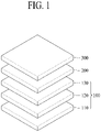
- FIG. 1 is a schematic view illustrating a structure of a display device having a visual angle control film according to one aspect of the present disclosure
- FIGS. 2 and 3 are stereoscopic view and top view illustrating a visual angle control film according to one aspect of the present disclosure
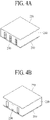
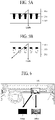
- FIGS. 4A, 4B , 5A and 5B are views illustrating operation states of a visual angle control mode and a visual angle non-control mode of a visual angle control film according to one aspect of the present disclosure.
- the display device may include a visual angle control film 200 disposed on a display panel 100 and a cover substrate 300.
- the display panel 100 may include a display 110 including a pixel array in which a plurality of pixels is disposed, a polarizer 120 disposed on the display 110, and a touch sensor 130 disposed on the polarizer 120.
- the touch sensor 130 may be omitted from the display panel 100.
- the display panel 100 may be any one of various display panels such as a liquid crystal display panel, an electroluminescent display panel, and a micro light emitting diode (LED) display panel.
- the electroluminescent display panel may be an Organic Light Emitting Diode (OLED) display panel, a Quantum-dot Light Emitting Diode display panel, or an Inorganic Light Emitting Diode display panel.
- OLED Organic Light Emitting Diode
- Quantum-dot Light Emitting Diode display panel or an Inorganic Light Emitting Diode display panel.
- the visual angle control film 200 may include a first substrate 210 in which a first transparent electrode is disposed, a second substrate 220 in which a second transparent electrode is disposed, a transparent insulating layer 230 disposed between the first and second substrates 210 and 220, and a light-shielding pattern 250 disposed in a plurality of grooves formed in the transparent insulating layer 230.
- Each of the first transparent electrode disposed in the first substrate 210 and the second transparent electrode disposed in the second substrate 220 may be supplied with a driving voltage applied from a driving circuit through an FPC 260.
- the light-shielding pattern 250 may be formed of a light-shielding material that absorbs light, and may be formed of an electronic ink that includes light-shielding particles moving in accordance with the voltages applied to the first and second transparent electrodes.
- the light-shielding pattern 250 is disposed to overlap a display area 240 in which the pixel array for displaying an image on the display panel 100 is positioned.
- the display area 240 has a structure surrounded by a bezel area 242.
- the light-shielding pattern 250 may be disposed in an oblique shape of a diagonal direction in the display area 240, but may be disposed in various shapes without being limited thereto.
- the light-shielding pattern 250 may be driven in accordance with the driving voltages applied to the first and second transparent electrodes of the first and second substrates 210 and 220, whereby a light-shielding height may be adjusted in accordance with a visual angle control mode and a visual angle non-control mode.
- the light-shielding pattern 250 driven in accordance with a first driving voltage applied to the first and second transparent electrodes of the first and second substrates 210 and 220 may be diffused in all the grooves of the transparent insulating layer 230, whereby the light-shielding height of the light-shielding pattern 250 may be increased to be equal to a groove height.
- the visual angle control film 200 may transmit light emitted from the display panel 100 toward a front direction in the visual angle control mode, but light advancing in a left or right side direction where a driver is positioned may be shielded by the light-shielding pattern 250.
- the light-shielding pattern 250 may be driven in accordance with a second driving voltage applied to the first and second transparent electrodes of the first and second substrates 210 and 220, whereby the light-shielding height of the light-shielding pattern 250 may be reduced such that the light-shielding pattern 250 may be positioned only in a bottom portion of the transparent insulating layer 230 adjacent to the display panel 100.
- the visual angle control film 200 may transmit light, which is emitted from the display panel 100, in both a front direction and a side direction in the visual angle non-control mode.
- the visual angle control film 200 may be driven in the visual angle non-control mode, whereby the image displayed on the display panel 100 may be provided to both the driver and a viewer of a passenger seat.
- FIG. 6 is a view illustrating a Moire Artifact phenomenon of a display device according to the related art.
- a display device 500 disposed to facing a passenger seat of a vehicle when the visual angle control film is driven in the visual angle control mode, light oriented toward the driver may be shielded, whereby the driver may view a black screen 500A but a viewer of the passenger seat may view an image 500B where Moire Artifact is generated by the visual angle control film.
- FIG. 7 is a flow chart illustrating a method for devising a design range of a visual angle control film according to one aspect of the present disclosure.
- the method for devising a design range of the visual angle control film may include applying a spec. (pixel size) of the display panel (S702), applying random specs. (thickness, interval and slope angle of the light-shielding pattern) of the visual angle control film (S704), simulating Moire Artifact (S706), and evaluating Moire level (S708).
- a spec. pixel size
- S704 random specs.
- S708 simulating Moire Artifact
- S708 evaluating Moire level
- the corresponding spec. (thickness, interval and slope angle of the light-shielding pattern) of the visual angle control film may be determined as a design range suitable for the visual angle control film (S712).
- the evaluation score of the Moire pattern is the threshold value 'th' or less (S710)
- the corresponding spec. (thickness, interval and slope angle of the light-shielding pattern) of the visual angle control film may be excluded from the design range (S714).
- This method for devising the design range of the visual angle control film may be repeated, whereby the design range of the visual angle control film for attenuating Moire Artifact may be determined (S712).
- the method for devising the design range of the visual angle control film may calculate a target range of thickness, interval and slope angle of the light-shielding pattern, which are three design elements of the visual angle control film and may attenuate Moire Artifact, by repeating the steps of FIG. 7 .
- FIGS. 8A and 8B are views illustrating design parameters of a light-shielding pattern in a visual angle control film according to one aspect of the present disclosure.
- the visual angle control film 200 may have an optimal design range in an interval W between the light-shielding patterns 250, a thickness d of the light-shielding pattern 250 and a slope angle ⁇ of the light-shielding pattern 250 to attenuate Moire Artifact.
- the visual angle control film may be designed to have a thickness d of the light-shielding pattern 250 in the range of 8% to 25% of a pixel size, an interval W between the light-shielding patterns 250 in the range of 33% to 39% of the pixel size, and a slope angle ⁇ of the light-shielding pattern 250 in the range of ⁇ 5° to 15° based on 90°, that is, 95° to 105° and 75° to 85°in the visual angle control mode.
- the pixel size means area of a pixel.
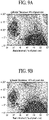
- FIGS. 9A to 9C are views illustrating a target design range of a visual angle control film according to one aspect of the present disclosure.
- an evaluation score of the Moire pattern has a target range or more (for example, 4 points or more) to attenuate Moire Artifact at a level that is acceptable to a viewer.
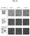
- FIG. 10 is a view illustrating a Moire level based on a size change of a pixel and a shape change of the pixel in a display device having a visual angle control film according to one aspect of the present disclosure.
- the design range of the visual angle control film devised in one aspect may be applied to display panels having various pixel shapes and sizes.
- interval W, thickness d, height H, etc. of the light-shielding pattern 250 may be adjusted differently depending on the position on the display panel 100. Therefore, luminance (transmittance) of the display panel 100, which is provided to a first viewer at a passenger seat (a first viewing position), may be improved through the visual angle control film 200 driven in the visual angle control mode, and light oriented toward a driver (a second viewer) of a driver's seat (a second viewing position) may effectively be shielded.
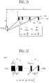
- FIG. 11 is a view illustrating differential application of intervals of light-shielding patterns of a visual angle control film according to one aspect of the present disclosure
- FIG. 12 is a view illustrating differential application of thicknesses of light-shielding patterns of a visual angle control film according to one aspect of the present disclosure
- FIGS. 13A and 13B are views illustrating an interval adjustment range of light-shielding patterns of a visual angle control film according to one aspect of the present disclosure
- FIG. 14 is a view illustrating differential application of heights of light-shielding patterns of a visual angle control film according to one aspect of the present disclosure
- FIG. 14 is a view illustrating differential application of heights of light-shielding patterns of a visual angle control film according to one aspect of the present disclosure
- FIGS. 16 and 17 are views illustrating a method for compensating for luminance deviation caused by differential application of intervals of light-shielding patterns of a visual angle control film according to one aspect of the present disclosure.
- intervals Ws and W E between the light-shielding patterns 250 may be set differently per position on the display panel 100 considering a driver's position, and a thickness and a height H of each light-shielding pattern 250 may equally be set.
- the first interval W S between the light-shielding patterns 250 may be set to be relatively small, and for a position far away from the driver, the second interval W E between the light-shielding patterns 250 may be set to be greater than the first interval Ws.
- the intervals Ws and W E between the light-shielding patterns 250 based on the position on the display panel 100 may be determined as shown in FIG. 11 and expressed by the following Equation 1.
- W S H tan ⁇ S
- ⁇ S H tan ⁇ S
- Ws may mean the first interval Ws between the light-shielding patterns 250 in the first position relatively close to the driver on the display panel 100, that is, the first position on the display panel 100 having a first horizontal distance S with the driver.
- the interval W E may mean the second interval W E between the light-shielding patterns 250 in the second position far away from the driver on the display panel 100, that is, the second position on the display panel 100 having a second horizontal distance E greater than the first horizontal distance S with the driver.
- H may mean the height of the light-shielding pattern 250.
- ⁇ S may mean an angle of light emitted from the first position of the display panel 100, which is relatively close to the driver, to the driver, and may be determined by an arc tangent function of a vertical distance D and the first horizontal distance S between the driver and the display panel 100.
- ⁇ E may mean an angle of light emitted from the second position of the display panel 100, which is relatively far away from the driver, to the driver, and may be determined by an arc tangent function of the vertical distance D and the second horizontal distance E between the driver and the display panel 100.
- the first interval W S between the light-shielding patterns 250 may be determined by a ratio of the height H of the light-shielding pattern 250 to a tangent function of a light emission angle ⁇ S of the display panel 100.
- the second interval W E between the light-shielding patterns 250 may be determined by a ratio of the height H of the light-shielding pattern 250 to a tangent function of a light emission angle ⁇ E of the display panel 100.
- thicknesses ds and d E of light-shielding patterns 250A and 250B and intervals Ws and W E between the light-shielding patterns 250A and 250B may be set differently per position on the display panel 100 considering a driver's position, and a height of each light-shielding pattern 250 may equally be set.
- the first thickness ds of the first light-shielding pattern 250A disposed in the first position close to the driver on the display panel 100 may be set to be relatively great, the first interval Ws between the first light-shielding patterns 250A may be set to be relatively small, the second thickness d E of the second light-shielding pattern 250B disposed in the second position far away from the driver may be set to be smaller than the first thickness ds, and the second interval W E between the second light-shielding patterns 250B may be set to be greater than the first interval Ws.
- the first interval Ws between the first light-shielding patterns 250A and the second interval W E between the second light-shielding patterns 250B based on the position on the display panel 100 may be determined by the above Equation 1.
- the first thickness d S of the first light-shielding pattern 250A having the first interval Ws and the second thickness d E of the second light-shielding pattern 250B having the second interval W E may be determined as shown in FIG. 12 and expressed by the following Equation 2.
- d S W ⁇ W S
- d E W ⁇ W E
- W may mean a certain interval W between the light-shielding patterns 250A and 250B.
- the first thickness ds of the first light-shielding pattern 250A having the first interval Ws in the first position close to the driver may be determined by a difference between the certain interval W and the first interval Ws
- the second thickness d E of the second light-shielding pattern 250B having the second interval W E in the second position far away from the driver may be determined by a difference between the certain interval W and the second interval W E .
- the intervals Ws and W E between the light-shielding patterns 250 may be set to be increased as the horizontal distances S and E with the driver are increased, but their variable range may be set to a threshold value Th as shown in FIG. 13B and thus limited to the range of 33% to 39% of a pixel size for preventing Moire from occurring when exceeding the threshold value Th.
- heights Hs and H E of light-shielding patterns 250C and 250D may be set differently per position on the display panel 100 considering a driver's position, intervals W between the light-shielding patterns 250C and 250D may equally be set, and thicknesses of the light-shielding patterns 250C and 250D may equally be set.
- the first height H S of the first light-shielding pattern 250C may be set to be relatively high for a position close to the driver on the display panel 100
- the second height H E of the second light-shielding pattern 250D may be set to be lower than the first height Hs for a position far away from the driver.
- H S and H E of the light-shielding patterns 250C and 250D based on the position on the display panel 100 may be determined as shown in FIG. 14 and expressed by the following Equation 3.
- H S W ⁇ tan ⁇ S
- ⁇ E tan ⁇ 1 D E
- Hs may mean the first height Hs of the first light-shielding pattern 250C in the first position relatively close to the driver on the display panel 100, that is, the first position on the display panel 100 having a first horizontal distance S with the driver.
- the height H E may mean the second height H E of the second light-shielding patterns 250D in the second position far away from the driver on the display panel 100, that is, the second position on the display panel 100 having a second horizontal distance E greater than the first horizontal distance S with the driver.
- ⁇ S may mean an angle of light emitted from the first position of the display panel 100, which is relatively close to the driver, to the driver, and may be determined by an arc tangent function of a vertical distance D and the first horizontal distance S between the driver and the display panel 100.
- ⁇ E may mean an angle of light emitted from the second position of the display panel 100, which is relatively far away from the driver, to the driver, and may be determined by an arc tangent function of the vertical distance D and the second horizontal distance E between the driver and the display panel 100.
- the first height H S of the first light-shielding pattern 250C may be determined by a multiplication result of a tangent function of the light emission angle ⁇ S of the display panel 100 and the interval W between the first light-shielding patterns 250C.
- the second height H E of the second light-shielding pattern 250D may be determined by a multiplication result of a tangent function of the light emission angle ⁇ E of the display panel 100 and the interval W between the second light-shielding patterns 250D.
- thicknesses ds and d E of light-shielding patterns 250E and 250F, intervals Ws and W E between the light-shielding patterns 250E and 250F and heights H S and H E of the light-shielding patterns 250E and 250F may be set differently per position on the display panel 100 considering a driver's position.
- the thicknesses ds and d E of the light-shielding patterns 250E and 250F, the intervals Ws and W E between the light-shielding patterns 250E and 250F and the heights H S and H E of the light-shielding patterns 250E and 250F per position on the display panel 100 considering the driver's position in FIG. 15 may be determined by the aforementioned Equations 1 to 3.
- the first thickness ds and the first height H S of the first light-shielding pattern 250E disposed in the first position close to the driver on the display panel 100 may be set to be relatively great, whereas the first interval Ws between the first light-shielding patterns 250E may be set to be relatively small.
- the second thickness d E and the second height H E of the second light-shielding pattern 250F disposed in the second position far away from the driver may be set to be smaller than the first thickness ds and the first height H S , respectively, and the second interval W E between the second light-shielding patterns 250F may be set to be greater than the first interval Ws.
- the visual angle control film and the display device having the same may improve transmittance through the visual angle control film by differentially applying the thicknesses and the intervals of the light-shielding patterns of the visual angle control film depending on the position on the display panel considering the driver's position, whereby luminance of the display device may be improved.
- the visual angle control film and the display device having the same may save the manufacturing cost of the visual angle control film by differentially applying the heights of the light-shielding patterns of the visual angle control film depending on the position on the display panel considering the driver's position.
- the intervals Ws and W E between the light-shielding patterns 250 in the visual angle control film according to one aspect are differentially applied in accordance with the position, the intervals Ws and W E between the light-shielding patterns 250 are increased in accordance with the increase of the horizontal distances S and E with the driver, whereby transmittance of light advancing toward a front side, that is, luminance F1 may be increased from L S to L E and therefore luminance deviation which is transmittance deviation may be generated in accordance with the position of the display panel.
- the luminance F1 per position based on the differential application of the intervals Ws and W E between the light-shielding patterns 250 in the visual angle control film may be increased to the luminance F2 by allowing low luminance L S in the display panel to be equal to high luminance L E , thereby uniformly compensating for luminance deviation.
- picture quality may be improved, and total luminance of the display device may be improved.
- the luminance F1 per position based on the differential application of the intervals Ws and W E between the light-shielding patterns 250 in the visual angle control film may be reduced to the luminance F3 by allowing high luminance L E in the display panel to be equal to low luminance L S , thereby uniformly compensating for luminance deviation.
- picture quality may be improved, and power consumption of the display device may be reduced.
- the visual angle control film has a thickness range, an angle range and an interval range of the light-shielding pattern, which are devised to minimize the Moire Artifact
- the Moire Artifact may be minimized without being affected by a pixel shape and size of the display panel, whereby display performance may be improved.
- At least one of an interval, a thickness or a height of the light-shielding pattern may differentially be applied depending on the position on the display panel having a different distance from a driver, whereby unnecessary light of the visual angle toward the driver may effectively be shielded, and at the same time luminance of an image provided to a viewer located at a passenger seat may be improved or the manufacturing cost of the visual angle control film may be reduced.
- the display device may provide uniform luminance by compensating for luminance deviation per position based on at least one differential application of an interval or a thickness of the light-shielding pattern in the visual angle control film, thereby improving display performance, and improving luminance or reducing power consumption.
- a display device according to one or more aspect of the present disclosure will be described below.
- a display device may be a display panel; and a visual angle control film disposed on the display panel, wherein the visual angle control film may include a plurality of light-shielding patterns for shielding light advancing in a side direction except for a front direction of the display panel in a visual angle control mode, and each of the plurality of light-shielding patterns may have a thickness in the range of 8% to 25% of a pixel area of the display panel, an interval in the range of 33% to 39% of the pixel size, and a slope angle in the range of ⁇ 5° to 15° based on 90°.
- the visual angle control film may include a first substrate in which a first transparent electrode is disposed; a second substrate in which a second transparent electrode is disposed; and a transparent insulating layer disposed between the first and second substrates, having grooves in which the plurality of light-shielding patterns are disposed, and a light-shielding height of each of the plurality of light-shielding patterns may be varied in a visual angle control mode and a visual angle non-control mode in accordance with driving voltages applied to the first and second transparent electrodes.
- the visual angle control film is positioned in the side direction of the display panel, and at least one of thicknesses, intervals or heights of the plurality of light-shielding patterns may be set differently in accordance with a position on the display panel considering a viewer's position to which the visual angle control mode is applied.
- a first interval of a first light-shielding pattern positioned in a first position close to the viewer may be set to be smaller than a second interval of a second light-shielding pattern positioned in a second position further away from the viewer than the first position, a thickness of the first light-shielding pattern may be equal to that of the second light-shielding pattern, and a height of the first light-shielding pattern may be equal to that of the second light-shielding pattern.
- a first thickness of a first light-shielding pattern positioned in a first position close to the viewer may be set to be greater than a second thickness of a second light-shielding pattern positioned in a second position further away from the viewer than the first position, a first interval between the first light-shielding patterns may be set to be smaller than a second interval between the second light-shielding patterns, and a height of the first light-shielding pattern may be equal to that of the second light-shielding pattern.
- a first height of a first light-shielding pattern positioned in a first position close to the viewer may be set to be higher than a second height of a second light-shielding pattern positioned in a second position further away from the viewer than the first position, a thickness of the first light-shielding pattern may be equal to that of the second light-shielding pattern, and an interval between the first light-shielding patterns may be equal to that between the second light-shielding patterns.
- a first thickness of a first light-shielding pattern positioned in a first position close to the viewer may be set to be greater than a second thickness of a second light-shielding pattern positioned in a second position further away from the viewer than the first position
- a first interval between the first light-shielding patterns may be set to be smaller than a second interval between the second light-shielding patterns
- a first height of the first light-shielding pattern may be set to be higher than a second height of the second light-shielding pattern.
- the interval between the light-shielding patterns may gradually be increased as the light-shielding pattern is far away from the viewer.
- the interval between the light-shielding patterns may gradually be increased, and the thickness of the light-shielding pattern may gradually be reduced as the light-shielding pattern is far away from the viewer.
- the height of the light-shielding pattern may gradually be reduced as the light-shielding pattern is far away from the viewer.
- the interval between the light-shielding patterns may gradually be increased, the thickness of the light-shielding pattern may gradually be reduced, and the height of the light-shielding pattern may gradually be decreased as the light-shielding pattern is far away from the viewer.
- the interval between the light-shielding patterns which is increased in accordance with the distance between the viewer and the light-shielding pattern, may be set within a threshold value that limits the interval in the range of 33% to 39% of the pixel size.
- Transmittance deviation of the visual angle control film based on the interval between the light-shielding patterns, which is different in accordance with the position of the display panel, may be compensated through luminance control of the display panel.
Landscapes
- Physics & Mathematics (AREA)
- Nonlinear Science (AREA)
- General Physics & Mathematics (AREA)
- Optics & Photonics (AREA)
- Chemical & Material Sciences (AREA)
- Life Sciences & Earth Sciences (AREA)
- Health & Medical Sciences (AREA)
- Chemical Kinetics & Catalysis (AREA)
- Electrochemistry (AREA)
- Molecular Biology (AREA)
- Crystallography & Structural Chemistry (AREA)
- Optical Elements Other Than Lenses (AREA)
- Devices For Indicating Variable Information By Combining Individual Elements (AREA)
- Electroluminescent Light Sources (AREA)
- Liquid Crystal (AREA)
Abstract
Description
- This application claims the benefit of the
Korean Patent Application No. 10-2020-0185604 filed on December 29, 2020 - The present disclosure relates to a display device having a visual angle control film, which may attenuate an interference phenomenon between a panel and a visual angle control film and effectively shield unnecessary light of a visual angle.
- Among display devices built in a vehicle, a display device arranged in front of a passenger seat provides a user with a desired image but includes a visual angle control film that shields light emitted toward a driver so as not to disturb the driver when the driver drives the vehicle.
- As the visual angle control film disposed on a display panel includes a light-shielding pattern for controlling a visual angle, a Moire Artifact which is an interference phenomenon between a pixel structure of the display panel and a light-shielding pattern of the visual angle control film is generated, whereby display performance is deteriorated. In this respect, a method that may attenuate the Moire Artifact is required.
- Moreover, the visual angle control film further needs a method that may effectively shield unnecessary light of a visual angle, which is oriented toward the driver.
- The disclosure of the above-described background art is owned by the inventor of the present disclosure to devise the present disclosure or is technical information acquired by a process of devising the present disclosure, but cannot be regarded as the known art disclosed to the general public before the present disclosure is disclosed.
- Accordingly, the present disclosure provides a display device having a visual angle control film, which may attenuate an interference phenomenon between a panel and a visual angle control film and effectively shield unnecessary light of a visual angle.
- In addition to the technical benefits of the present disclosure as mentioned above, additional technical benefits and features of the present disclosure will be clearly understood by those skilled in the art from the following description of the present disclosure.
- A display device according to an aspect of the present disclosure may comprise a display panel; and a visual angle control film disposed on the display panel, wherein the visual angle control film may include a plurality of light-shielding patterns for shielding light advancing in a side direction except for a front direction of the display panel in a visual angle control mode, and each of the plurality of light-shielding patterns may have a thickness in the range of 8% to 25% of a pixel area of the display panel, an interval in the range of 33% to 39% of the pixel size, and a slope angle in the range of ±5° to 15° based on 90°.
- In addition to the features of the present disclosure as mentioned above, additional technical benefits and features of the present disclosure will be included within this description, be within the scope of the present disclosure, and be protected by the following claims. Nothing in this section should be taken as a limitation on those claims. Further aspects and advantages are discussed below in conjunction with aspect of the disclosure. It is to be understood that both the foregoing general description and the following detailed description of the present disclosure are exemplary and explanatory and are intended to provide further explanation of the inventive concepts as claimed.
- The accompanying drawings, which are included to provide a further understanding of the disclosure and are incorporated in and constitute a part of this application, illustrate aspect of the disclosure and together with the description serve to explain the principles of the disclosure. In the drawings:
-
FIG. 1 is a schematic view illustrating a structure of a display device having a visual angle control film according to one aspect of the present disclosure; -
FIG. 2 is a stereoscopic view illustrating a structure of a visual angle control film according to one aspect of the present disclosure; -
FIG. 3 is a top view illustrating a visual angle control film according to one aspect of the present disclosure; -
FIGS. 4A, 4B ,5A and 5B are views illustrating operation states of a visual angle control mode and a visual angle non-control mode of a visual angle control film according to one aspect of the present disclosure; -
FIG. 6 is a view illustrating a Moire Artifact phenomenon of a display device according to the related art; -
FIG. 7 is a flow chart illustrating a method for devising a design range of a visual angle control film according to one aspect of the present disclosure; -
FIGS. 8A and 8B are views illustrating three design parameters of a light-shielding pattern in a visual angle control film according to one aspect of the present disclosure; -
FIGS. 9A to 9C are views illustrating a target design range of a visual angle control film according to one aspect of the present disclosure; -
FIG. 10 is a view illustrating a Moire level based on a size change of a pixel and a shape change of the pixel in a display device having a visual angle control film according to one aspect of the present disclosure; -
FIG. 11 is a view illustrating differential application of intervals of light-shielding patterns of a visual angle control film according to one aspect of the present disclosure; -
FIG. 12 is a view illustrating differential application of thicknesses of light-shielding patterns of a visual angle control film according to one aspect of the present disclosure; -
FIGS. 13A and 13B are views illustrating an interval adjustment range of light-shielding patterns in a visual angle control film according to one aspect of the present disclosure; -
FIG. 14 is a view illustrating differential application of heights of light-shielding patterns of a visual angle control film according to one aspect of the present disclosure; -
FIG. 15 is a view illustrating differential application of intervals, thicknesses and heights of light-shielding patterns of a visual angle control film according to one aspect of the present disclosure; and -
FIGS. 16 and 17 are views illustrating a method for compensating for luminance deviation caused by differential application of intervals of light-shielding patterns of a visual angle control film according to one aspect of the present disclosure. - Advantages and features of the present disclosure, and implementation methods thereof will be clarified through following aspect described with reference to the accompanying drawings. The present disclosure may, however, be embodied in different forms and should not be construed as limited to the aspect set forth herein. Rather, these aspect are provided so that this disclosure will be thorough and complete, and will fully convey the scope of the present disclosure to those skilled in the art. Further, the present disclosure is only defined by scopes of claims.
- A shape, a size, a ratio, an angle, and a number disclosed in the drawings for describing aspect of the present disclosure are merely an example, and thus, the present disclosure is not limited to the illustrated details. Like reference numerals refer to like elements throughout the specification. In the following description, when the detailed description of the relevant known function or configuration is determined to unnecessarily obscure the important point of the present disclosure, the detailed description will be omitted. In a case where 'comprise', 'have', and 'include' described in the present specification are used, another part may be added unless 'only∼' is used. The terms of a singular form may include plural forms unless referred to the contrary.
- In construing an element, the element is construed as including an error range although there is no explicit description.
- In describing a position relationship, for example, when a position relation between two parts is described as "on," "over," "under," and "next," one or more other parts may be disposed between the two parts unless a more limiting term, such as "just" or "direct(ly)" is used.
- In describing a time relationship, for example, when the temporal order is described as, for example, "after," "subsequent," "next," and "before," a case which is not continuous may be included unless a more limiting term, such as "just," "immediate(ly)," or "direct(ly)" is used.
- It will be understood that, although the terms "first," "second," etc. may be used herein to describe various elements, these elements should not be limited by these terms. These terms are only used to distinguish one element from another. For example, a first element could be termed a second element, and, similarly, a second element could be termed a first element, without departing from the scope of the present disclosure.
- In describing the elements of the present disclosure, the terms "first," "second," "A," "B," "(a)," "(b)," etc., may be used. These terms are intended to identify the corresponding elements from the other elements, and basis, order, or number of the corresponding elements should not be limited by these terms. The expression that an element or layer is "connected," "coupled," or "adhered" to another element or layer, the element or layer can not only be directly connected or adhered to another element or layer, but also be indirectly connected or adhered to another element or layer with one or more intervening elements or layers "disposed" between the elements or layers, unless otherwise specified.
- The term "at least one" should be understood as including any and all combinations of one or more among the associated listed elements. For example, the meaning of "at least one or more of a first element, a second element, and a third element" denotes the combination of all elements proposed from two or more of the first element, the second element, and the third element as well as the first element, the second element, or the third element.
- Features of various aspect of the present disclosure may be partially or overall coupled to or combined with each other, and may be variously inter-operated with each other and driven technically as those skilled in the art can sufficiently understand. The aspect of the present disclosure may be carried out independently from each other, or may be carried out together in co-dependent relationship.
- Hereinafter, the aspect of the present disclosure will be described with reference to the accompanying drawings. Since a scale of each of elements shown in the accompanying drawings is different from an actual scale for convenience of description, the present disclosure is not limited to the shown scale.
-
FIG. 1 is a schematic view illustrating a structure of a display device having a visual angle control film according to one aspect of the present disclosure,FIGS. 2 and 3 are stereoscopic view and top view illustrating a visual angle control film according to one aspect of the present disclosure, andFIGS. 4A, 4B ,5A and 5B are views illustrating operation states of a visual angle control mode and a visual angle non-control mode of a visual angle control film according to one aspect of the present disclosure. - Referring to
FIG. 1 , the display device according to one aspect of the present disclosure may include a visualangle control film 200 disposed on adisplay panel 100 and acover substrate 300. - The
display panel 100 may include adisplay 110 including a pixel array in which a plurality of pixels is disposed, apolarizer 120 disposed on thedisplay 110, and atouch sensor 130 disposed on thepolarizer 120. Thetouch sensor 130 may be omitted from thedisplay panel 100. - The
display panel 100 may be any one of various display panels such as a liquid crystal display panel, an electroluminescent display panel, and a micro light emitting diode (LED) display panel. The electroluminescent display panel may be an Organic Light Emitting Diode (OLED) display panel, a Quantum-dot Light Emitting Diode display panel, or an Inorganic Light Emitting Diode display panel. - Referring to
FIGS. 2 and 3 , the visualangle control film 200 may include afirst substrate 210 in which a first transparent electrode is disposed, asecond substrate 220 in which a second transparent electrode is disposed, a transparent insulatinglayer 230 disposed between the first andsecond substrates shielding pattern 250 disposed in a plurality of grooves formed in the transparent insulatinglayer 230. - Each of the first transparent electrode disposed in the
first substrate 210 and the second transparent electrode disposed in thesecond substrate 220 may be supplied with a driving voltage applied from a driving circuit through anFPC 260. - The light-
shielding pattern 250 may be formed of a light-shielding material that absorbs light, and may be formed of an electronic ink that includes light-shielding particles moving in accordance with the voltages applied to the first and second transparent electrodes. - The light-
shielding pattern 250 is disposed to overlap adisplay area 240 in which the pixel array for displaying an image on thedisplay panel 100 is positioned. Thedisplay area 240 has a structure surrounded by abezel area 242. The light-shielding pattern 250 may be disposed in an oblique shape of a diagonal direction in thedisplay area 240, but may be disposed in various shapes without being limited thereto. - The light-
shielding pattern 250 may be driven in accordance with the driving voltages applied to the first and second transparent electrodes of the first andsecond substrates - Referring to
FIGS. 4A and5A , in the visual angle control mode, the light-shielding pattern 250 driven in accordance with a first driving voltage applied to the first and second transparent electrodes of the first andsecond substrates layer 230, whereby the light-shielding height of the light-shielding pattern 250 may be increased to be equal to a groove height. The visualangle control film 200 may transmit light emitted from thedisplay panel 100 toward a front direction in the visual angle control mode, but light advancing in a left or right side direction where a driver is positioned may be shielded by the light-shielding pattern 250. - Referring to
FIGS. 4B and5B , in the visual angle non-control mode, the light-shielding pattern 250 may be driven in accordance with a second driving voltage applied to the first and second transparent electrodes of the first andsecond substrates shielding pattern 250 may be reduced such that the light-shielding pattern 250 may be positioned only in a bottom portion of the transparent insulatinglayer 230 adjacent to thedisplay panel 100. The visualangle control film 200 may transmit light, which is emitted from thedisplay panel 100, in both a front direction and a side direction in the visual angle non-control mode. Therefore, when the driver desires to view an image displayed on thedisplay panel 100 like the case that a vehicle does not drive, the visualangle control film 200 may be driven in the visual angle non-control mode, whereby the image displayed on thedisplay panel 100 may be provided to both the driver and a viewer of a passenger seat. -
FIG. 6 is a view illustrating a Moire Artifact phenomenon of a display device according to the related art. - Referring to
FIG. 6 , in adisplay device 500 disposed to facing a passenger seat of a vehicle, when the visual angle control film is driven in the visual angle control mode, light oriented toward the driver may be shielded, whereby the driver may view ablack screen 500A but a viewer of the passenger seat may view animage 500B where Moire Artifact is generated by the visual angle control film. - In order to attenuate such Moire Artifact, a design range of the visual angle control film according to one aspect may be devised as follows.
-
FIG. 7 is a flow chart illustrating a method for devising a design range of a visual angle control film according to one aspect of the present disclosure. - Referring to
FIG. 7 , the method for devising a design range of the visual angle control film according to one aspect may include applying a spec. (pixel size) of the display panel (S702), applying random specs. (thickness, interval and slope angle of the light-shielding pattern) of the visual angle control film (S704), simulating Moire Artifact (S706), and evaluating Moire level (S708). When an evaluation score of a Moire pattern is greater than a threshold value 'th' (S710), the corresponding spec. (thickness, interval and slope angle of the light-shielding pattern) of the visual angle control film may be determined as a design range suitable for the visual angle control film (S712). On the other hand, when the evaluation score of the Moire pattern is the threshold value 'th' or less (S710), the corresponding spec. (thickness, interval and slope angle of the light-shielding pattern) of the visual angle control film may be excluded from the design range (S714). This method for devising the design range of the visual angle control film may be repeated, whereby the design range of the visual angle control film for attenuating Moire Artifact may be determined (S712). - The method for devising the design range of the visual angle control film according to one aspect may calculate a target range of thickness, interval and slope angle of the light-shielding pattern, which are three design elements of the visual angle control film and may attenuate Moire Artifact, by repeating the steps of
FIG. 7 . -
FIGS. 8A and 8B are views illustrating design parameters of a light-shielding pattern in a visual angle control film according to one aspect of the present disclosure. - Referring to
FIGS. 8A and 8B , the visualangle control film 200 may have an optimal design range in an interval W between the light-shieldingpatterns 250, a thickness d of the light-shielding pattern 250 and a slope angle θ of the light-shielding pattern 250 to attenuate Moire Artifact. - For example, in order to attenuate Moire Artifact, it is preferable that the visual angle control film according to one aspect may be designed to have a thickness d of the light-
shielding pattern 250 in the range of 8% to 25% of a pixel size, an interval W between the light-shieldingpatterns 250 in the range of 33% to 39% of the pixel size, and a slope angle θ of the light-shielding pattern 250 in the range of ±5° to 15° based on 90°, that is, 95° to 105° and 75° to 85°in the visual angle control mode. The pixel size means area of a pixel. -
FIGS. 9A to 9C are views illustrating a target design range of a visual angle control film according to one aspect of the present disclosure. - Referring to
FIGS. 9A to 9C , under the condition that the thickness of the light-shielding pattern (Resin) is 8%, 16%, or 25% of the pixel size, the interval of the light-shielding pattern (Resin) is in the range of 33% to 39% of the pixel size and the slope angle (based on 90°) of the light-shielding pattern is in the design range of ±5°to 15°, it is noted that an evaluation score of the Moire pattern has a target range or more (for example, 4 points or more) to attenuate Moire Artifact at a level that is acceptable to a viewer. -
FIG. 10 is a view illustrating a Moire level based on a size change of a pixel and a shape change of the pixel in a display device having a visual angle control film according to one aspect of the present disclosure. - Referring to
FIG. 10 , as a result of Moire level evaluated when the visual angle control film according to one aspect has a spec. A (thickness, interval and slope angle) of the light-shielding pattern in a target range, it is noted that there is little difference in Moire levels based on a shape change of a pixel or a size change of a pixel. Therefore, the design range of the visual angle control film devised in one aspect may be applied to display panels having various pixel shapes and sizes. - Meanwhile, when the visual angle control film has specs. B and C (thickness, interval and slope angle) gotten out of the target range, it is noted that the Moire level is recognized but there is little difference in Moire levels recognized depending on a shape change of a pixel or size change of a pixel.
- In the visual
angle control film 200 of the display device according to one aspect, interval W, thickness d, height H, etc. of the light-shielding pattern 250 may be adjusted differently depending on the position on thedisplay panel 100. Therefore, luminance (transmittance) of thedisplay panel 100, which is provided to a first viewer at a passenger seat (a first viewing position), may be improved through the visualangle control film 200 driven in the visual angle control mode, and light oriented toward a driver (a second viewer) of a driver's seat (a second viewing position) may effectively be shielded. -
FIG. 11 is a view illustrating differential application of intervals of light-shielding patterns of a visual angle control film according to one aspect of the present disclosure,FIG. 12 is a view illustrating differential application of thicknesses of light-shielding patterns of a visual angle control film according to one aspect of the present disclosure,FIGS. 13A and 13B are views illustrating an interval adjustment range of light-shielding patterns of a visual angle control film according to one aspect of the present disclosure,FIG. 14 is a view illustrating differential application of heights of light-shielding patterns of a visual angle control film according to one aspect of the present disclosure,FIG. 15 is a view illustrating differential application of intervals, thicknesses and heights of light-shielding patterns of a visual angle control film according to one aspect of the present disclosure, andFIGS. 16 and 17 are views illustrating a method for compensating for luminance deviation caused by differential application of intervals of light-shielding patterns of a visual angle control film according to one aspect of the present disclosure. - Referring to
FIG. 11 , in the visualangle control film 200 according to one aspect, intervals Ws and WE between the light-shieldingpatterns 250 may be set differently per position on thedisplay panel 100 considering a driver's position, and a thickness and a height H of each light-shielding pattern 250 may equally be set. For a position close to a driver on thedisplay panel 100, the first interval WS between the light-shieldingpatterns 250 may be set to be relatively small, and for a position far away from the driver, the second interval WE between the light-shieldingpatterns 250 may be set to be greater than the first interval Ws. - The intervals Ws and WE between the light-shielding
patterns 250 based on the position on thedisplay panel 100 may be determined as shown inFIG. 11 and expressed by the followingEquation 1.
- In
FIG. 11 and theabove Equation 1, Ws may mean the first interval Ws between the light-shieldingpatterns 250 in the first position relatively close to the driver on thedisplay panel 100, that is, the first position on thedisplay panel 100 having a first horizontal distance S with the driver. The interval WE may mean the second interval WE between the light-shieldingpatterns 250 in the second position far away from the driver on thedisplay panel 100, that is, the second position on thedisplay panel 100 having a second horizontal distance E greater than the first horizontal distance S with the driver. H may mean the height of the light-shielding pattern 250. θS may mean an angle of light emitted from the first position of thedisplay panel 100, which is relatively close to the driver, to the driver, and may be determined by an arc tangent function of a vertical distance D and the first horizontal distance S between the driver and thedisplay panel 100. θE may mean an angle of light emitted from the second position of thedisplay panel 100, which is relatively far away from the driver, to the driver, and may be determined by an arc tangent function of the vertical distance D and the second horizontal distance E between the driver and thedisplay panel 100. - Referring to
FIG. 11 and theEquation 1, in the first position of thedisplay panel 100, which is relatively close to the driver, the first interval WS between the light-shieldingpatterns 250 may be determined by a ratio of the height H of the light-shielding pattern 250 to a tangent function of a light emission angle θS of thedisplay panel 100. In the second position of thedisplay panel 100, which is relatively far away from the driver, the second interval WE between the light-shieldingpatterns 250 may be determined by a ratio of the height H of the light-shielding pattern 250 to a tangent function of a light emission angle θE of thedisplay panel 100. - Referring to
FIG. 12 , in a visualangle control film 200A according to one aspect, thicknesses ds and dE of light-shielding patterns shielding patterns display panel 100 considering a driver's position, and a height of each light-shielding pattern 250 may equally be set. The first thickness ds of the first light-shielding pattern 250A disposed in the first position close to the driver on thedisplay panel 100 may be set to be relatively great, the first interval Ws between the first light-shielding patterns 250A may be set to be relatively small, the second thickness dE of the second light-shielding pattern 250B disposed in the second position far away from the driver may be set to be smaller than the first thickness ds, and the second interval WE between the second light-shieldingpatterns 250B may be set to be greater than the first interval Ws. - The first interval Ws between the first light-
shielding patterns 250A and the second interval WE between the second light-shieldingpatterns 250B based on the position on thedisplay panel 100 may be determined by theabove Equation 1. The first thickness dS of the first light-shielding pattern 250A having the first interval Ws and the second thickness dE of the second light-shielding pattern 250B having the second interval WE may be determined as shown inFIG. 12 and expressed by the following Equation 2.
- In
FIG. 12 and the above Equation 2, W may mean a certain interval W between the light-shielding patterns - Referring to
FIG. 12 and the Equation 2, the first thickness ds of the first light-shielding pattern 250A having the first interval Ws in the first position close to the driver may be determined by a difference between the certain interval W and the first interval Ws, and the second thickness dE of the second light-shielding pattern 250B having the second interval WE in the second position far away from the driver may be determined by a difference between the certain interval W and the second interval WE. - Referring to
FIG. 13A , the intervals Ws and WE between the light-shieldingpatterns 250 may be set to be increased as the horizontal distances S and E with the driver are increased, but their variable range may be set to a threshold value Th as shown inFIG. 13B and thus limited to the range of 33% to 39% of a pixel size for preventing Moire from occurring when exceeding the threshold value Th. - Referring to
FIG. 14 , in a visualangle control film 200C according to one aspect, heights Hs and HE of light-shieldingpatterns display panel 100 considering a driver's position, intervals W between the light-shieldingpatterns patterns shielding pattern 250C may be set to be relatively high for a position close to the driver on thedisplay panel 100, and the second height HE of the second light-shielding pattern 250D may be set to be lower than the first height Hs for a position far away from the driver. - The heights HS and HE of the light-shielding
patterns display panel 100 may be determined as shown inFIG. 14 and expressed by the followingEquation 3.
- In
FIG. 14 and theabove Equation 3, Hs may mean the first height Hs of the first light-shielding pattern 250C in the first position relatively close to the driver on thedisplay panel 100, that is, the first position on thedisplay panel 100 having a first horizontal distance S with the driver. The height HE may mean the second height HE of the second light-shielding patterns 250D in the second position far away from the driver on thedisplay panel 100, that is, the second position on thedisplay panel 100 having a second horizontal distance E greater than the first horizontal distance S with the driver. θS may mean an angle of light emitted from the first position of thedisplay panel 100, which is relatively close to the driver, to the driver, and may be determined by an arc tangent function of a vertical distance D and the first horizontal distance S between the driver and thedisplay panel 100. θE may mean an angle of light emitted from the second position of thedisplay panel 100, which is relatively far away from the driver, to the driver, and may be determined by an arc tangent function of the vertical distance D and the second horizontal distance E between the driver and thedisplay panel 100. - Referring to
FIG. 14 and theEquation 3, in the first position of thedisplay panel 100, which is relatively close to the driver, the first height HS of the first light-shielding pattern 250C may be determined by a multiplication result of a tangent function of the light emission angle θS of thedisplay panel 100 and the interval W between the first light-shieldingpatterns 250C. In the second position of thedisplay panel 100, which is relatively far away from the driver, the second height HE of the second light-shielding pattern 250D may be determined by a multiplication result of a tangent function of the light emission angle θE of thedisplay panel 100 and the interval W between the second light-shielding patterns 250D. - Referring to
FIG. 15 , in a visualangle control film 200E according to one aspect, thicknesses ds and dE of light-shielding patterns shielding patterns shielding patterns display panel 100 considering a driver's position. - The thicknesses ds and dE of the light-
shielding patterns shielding patterns shielding patterns display panel 100 considering the driver's position inFIG. 15 may be determined by theaforementioned Equations 1 to 3. - In
FIG. 15 , the first thickness ds and the first height HS of the first light-shielding pattern 250E disposed in the first position close to the driver on thedisplay panel 100 may be set to be relatively great, whereas the first interval Ws between the first light-shielding patterns 250E may be set to be relatively small. The second thickness dE and the second height HE of the second light-shielding pattern 250F disposed in the second position far away from the driver may be set to be smaller than the first thickness ds and the first height HS, respectively, and the second interval WE between the second light-shielding patterns 250F may be set to be greater than the first interval Ws. - In this way, the visual angle control film and the display device having the same according to one aspect may improve transmittance through the visual angle control film by differentially applying the thicknesses and the intervals of the light-shielding patterns of the visual angle control film depending on the position on the display panel considering the driver's position, whereby luminance of the display device may be improved.
- The visual angle control film and the display device having the same according to one aspect may save the manufacturing cost of the visual angle control film by differentially applying the heights of the light-shielding patterns of the visual angle control film depending on the position on the display panel considering the driver's position.
- Referring to
FIGS. 16 and 17 , when the intervals Ws and WE between the light-shieldingpatterns 250 in the visual angle control film according to one aspect are differentially applied in accordance with the position, the intervals Ws and WE between the light-shieldingpatterns 250 are increased in accordance with the increase of the horizontal distances S and E with the driver, whereby transmittance of light advancing toward a front side, that is, luminance F1 may be increased from LS to LE and therefore luminance deviation which is transmittance deviation may be generated in accordance with the position of the display panel. - Referring to
FIG. 16 , the luminance F1 per position based on the differential application of the intervals Ws and WE between the light-shieldingpatterns 250 in the visual angle control film may be increased to the luminance F2 by allowing low luminance LS in the display panel to be equal to high luminance LE, thereby uniformly compensating for luminance deviation. As a result, picture quality may be improved, and total luminance of the display device may be improved. - Referring to
FIG. 17 , the luminance F1 per position based on the differential application of the intervals Ws and WE between the light-shieldingpatterns 250 in the visual angle control film may be reduced to the luminance F3 by allowing high luminance LE in the display panel to be equal to low luminance LS, thereby uniformly compensating for luminance deviation. As a result, picture quality may be improved, and power consumption of the display device may be reduced. - In the display device according to one or more aspect of the present disclosure, as the visual angle control film has a thickness range, an angle range and an interval range of the light-shielding pattern, which are devised to minimize the Moire Artifact, the Moire Artifact may be minimized without being affected by a pixel shape and size of the display panel, whereby display performance may be improved.
- In the display device according to one or more aspect of the present disclosure, at least one of an interval, a thickness or a height of the light-shielding pattern may differentially be applied depending on the position on the display panel having a different distance from a driver, whereby unnecessary light of the visual angle toward the driver may effectively be shielded, and at the same time luminance of an image provided to a viewer located at a passenger seat may be improved or the manufacturing cost of the visual angle control film may be reduced.
- The display device according to one or more aspect of the present disclosure may provide uniform luminance by compensating for luminance deviation per position based on at least one differential application of an interval or a thickness of the light-shielding pattern in the visual angle control film, thereby improving display performance, and improving luminance or reducing power consumption.
- A display device according to one or more aspect of the present disclosure will be described below.
- A display device according to example there may be a display panel; and a visual angle control film disposed on the display panel, wherein the visual angle control film may include a plurality of light-shielding patterns for shielding light advancing in a side direction except for a front direction of the display panel in a visual angle control mode, and each of the plurality of light-shielding patterns may have a thickness in the range of 8% to 25% of a pixel area of the display panel, an interval in the range of 33% to 39% of the pixel size, and a slope angle in the range of ±5° to 15° based on 90°.
- The visual angle control film may include a first substrate in which a first transparent electrode is disposed; a second substrate in which a second transparent electrode is disposed; and a transparent insulating layer disposed between the first and second substrates, having grooves in which the plurality of light-shielding patterns are disposed, and a light-shielding height of each of the plurality of light-shielding patterns may be varied in a visual angle control mode and a visual angle non-control mode in accordance with driving voltages applied to the first and second transparent electrodes.
- The visual angle control film is positioned in the side direction of the display panel, and at least one of thicknesses, intervals or heights of the plurality of light-shielding patterns may be set differently in accordance with a position on the display panel considering a viewer's position to which the visual angle control mode is applied.
- In the visual angle control film, a first interval of a first light-shielding pattern positioned in a first position close to the viewer may be set to be smaller than a second interval of a second light-shielding pattern positioned in a second position further away from the viewer than the first position, a thickness of the first light-shielding pattern may be equal to that of the second light-shielding pattern, and a height of the first light-shielding pattern may be equal to that of the second light-shielding pattern.
- In the visual angle control film, a first thickness of a first light-shielding pattern positioned in a first position close to the viewer may be set to be greater than a second thickness of a second light-shielding pattern positioned in a second position further away from the viewer than the first position, a first interval between the first light-shielding patterns may be set to be smaller than a second interval between the second light-shielding patterns, and a height of the first light-shielding pattern may be equal to that of the second light-shielding pattern.
- In the visual angle control film, a first height of a first light-shielding pattern positioned in a first position close to the viewer may be set to be higher than a second height of a second light-shielding pattern positioned in a second position further away from the viewer than the first position, a thickness of the first light-shielding pattern may be equal to that of the second light-shielding pattern, and an interval between the first light-shielding patterns may be equal to that between the second light-shielding patterns.
- In the visual angle control film, a first thickness of a first light-shielding pattern positioned in a first position close to the viewer may be set to be greater than a second thickness of a second light-shielding pattern positioned in a second position further away from the viewer than the first position, a first interval between the first light-shielding patterns may be set to be smaller than a second interval between the second light-shielding patterns, and a first height of the first light-shielding pattern may be set to be higher than a second height of the second light-shielding pattern.
- In the visual angle control film, the interval between the light-shielding patterns may gradually be increased as the light-shielding pattern is far away from the viewer.
- In the visual angle control film, the interval between the light-shielding patterns may gradually be increased, and the thickness of the light-shielding pattern may gradually be reduced as the light-shielding pattern is far away from the viewer.
- In the visual angle control film, the height of the light-shielding pattern may gradually be reduced as the light-shielding pattern is far away from the viewer.
- In the visual angle control film, the interval between the light-shielding patterns may gradually be increased, the thickness of the light-shielding pattern may gradually be reduced, and the height of the light-shielding pattern may gradually be decreased as the light-shielding pattern is far away from the viewer.
- The interval between the light-shielding patterns, which is increased in accordance with the distance between the viewer and the light-shielding pattern, may be set within a threshold value that limits the interval in the range of 33% to 39% of the pixel size.
- Transmittance deviation of the visual angle control film based on the interval between the light-shielding patterns, which is different in accordance with the position of the display panel, may be compensated through luminance control of the display panel.
- Further examples are set out in the numbered clauses below:
- 1. A display device comprising:
- a display panel; and
- a visual angle control film disposed on the display panel,
- wherein the visual angle control film includes a plurality of light-shielding patterns for shielding light advancing in a side direction except for a front direction of the display panel in a visual angle control mode, and
- each of the plurality of light-shielding patterns has a thickness in the range of 8% to 25% of a pixel area of the display panel, an interval in the range of 33% to 39% of the pixel size, and a slope angle in the range of ±5° to 15° based on 90°.
- 2. The display device of
clause 1, wherein the visual angle control film includes:- a first substrate in which a first transparent electrode is disposed;
- a second substrate in which a second transparent electrode is disposed; and
- a transparent insulating layer disposed between the first and second substrates, having grooves in which the plurality of light-shielding patterns are disposed,
- wherein a light-shielding height of each of the plurality of light-shielding patterns is varied in a visual angle control mode and a visual angle non-control mode in accordance with driving voltages applied to the first and second transparent electrodes.
- 3. The display device of
clause 1, wherein the visual angle control film is positioned in the side direction of the display panel, and at least one of thicknesses, intervals or heights of the plurality of light-shielding patterns is set differently in accordance with a position on the display panel considering a viewer's position to which the visual angle control mode is applied. - 4. The display device of
clause 3, wherein, in the visual angle control film,- a first interval of a first light-shielding pattern positioned in a first position close to the viewer is set to be smaller than a second interval of a second light-shielding pattern positioned in a second position further away from the viewer than the first position,
- a thickness of the first light-shielding pattern is equal to that of the second light-shielding pattern, and
- a height of the first light-shielding pattern is equal to that of the second light-shielding pattern.
- 5. The display device of
clause 3, wherein, in the visual angle control film,- a first thickness of a first light-shielding pattern positioned in a first position close to the viewer is set to be greater than a second thickness of a second light-shielding pattern positioned in a second position further away from the viewer than the first position,
- a first interval between the first light-shielding patterns is set to be smaller than a second interval between the second light-shielding patterns, and
- a height of the first light-shielding pattern is equal to that of the second light-shielding pattern.
- 6. The display device of
clause 3, wherein, in the visual angle control film,- a first height of a first light-shielding pattern positioned in a first position close to the viewer is set to be higher than a second height of a second light-shielding pattern positioned in a second position further away from the viewer than the first position,
- a thickness of the first light-shielding pattern is equal to that of the second light-shielding pattern, and
- an interval between the first light-shielding patterns is equal to that between the second light-shielding patterns.
- 7. The display device of
clause 3, wherein, in the visual angle control film,- a first thickness of a first light-shielding pattern positioned in a first position close to the viewer is set to be greater than a second thickness of a second light-shielding pattern positioned in a second position further away from the viewer than the first position,
- a first interval between the first light-shielding patterns is set to be smaller than a second interval between the second light-shielding patterns, and
- a first height of the first light-shielding pattern is set to be higher than a second height of the second light-shielding pattern.
- 8. The display device of any one of clauses 4, 5 and 7, wherein the first interval between the first light-shielding patterns is set by applying a vertical distance between the viewer and the display panel, a first horizontal distance between the viewer and the first position of the display panel and the height of the first light-shielding pattern, and
wherein the second interval between the second light-shielding patterns is set by applying a vertical distance between the viewer and the display panel, a second horizontal distance between the viewer and the second position of the display panel and the height of the second light-shielding pattern. - 9. The display device of any one of clauses 5 and 7, wherein the first thickness of the first light-shielding pattern is set in accordance with the first interval between the first light-shielding patterns, and the second thickness of the second light-shielding pattern is set in accordance with the second interval between the second light-shielding patterns.
- 10. The display device of any one of clauses 6 and 7, wherein the first height of the first light-shielding pattern is set by applying a vertical distance between the viewer and the display panel, a first horizontal distance between the viewer and the first position of the display panel and the interval between the first light-shielding patterns, and the second height of the second light-shielding patterns is set by applying a vertical distance between the viewer and the display panel, a second horizontal distance between the viewer and the second position of the display panel and the interval between the second light-shielding patterns.
- 11. The display device of
clause 3, wherein, in the visual angle control film, the interval between the light-shielding patterns is gradually increased as the light-shielding pattern is far away from the viewer. - 12. The display device of
clause 3, wherein, in the visual angle control film, the interval between the light-shielding patterns is gradually increased, and the thickness of the light-shielding pattern is gradually reduced as the light-shielding pattern is far away from the viewer. - 13. The display device of
clause 3, wherein, in the visual angle control film, the height of the light-shielding pattern is gradually reduced as the light-shielding pattern is far away from the viewer. - 14. The display device of
clause 3, wherein, in the visual angle control film, the interval between the light-shielding patterns is gradually increased, the thickness of the light-shielding pattern is gradually reduced, and the height of the light-shielding pattern is gradually reduced as the light-shielding pattern is far away from the viewer. - 15. The display device of any one of clauses 11, 12 and 14, wherein the interval between the light-shielding patterns, which is increased in accordance with the distance between the viewer and the light-shielding pattern, is set within a threshold value that limits the interval in the range of 33% to 39% of the pixel size.
- 16. The display device of
clause 3, wherein transmittance deviation of the visual angle control film based on the interval between the light-shielding patterns, which is different in accordance with the position of the display panel, is compensated through luminance control of the display panel. - It will be apparent to those skilled in the art that the present disclosure described above is not limited by the above-described aspect and the accompanying drawings and that various substitutions, modifications, and variations can be made in the present disclosure without departing from the scope of the disclosures.
Claims (15)
- A display device comprising:a display panel; anda visual angle control film disposed on the display panel,wherein the visual angle control film includes a plurality of light-shielding patterns for shielding light advancing in a side direction except for a front direction of the display panel in a visual angle control mode, andeach of the plurality of light-shielding patterns has a thickness in the range of 8% to 25% of a pixel area of the display panel, an interval in the range of 33% to 39% of the pixel size, and a slope angle in the range of ±5° to 15° based on 90°.
- The display device of claim 1, wherein the visual angle control film includes:a first substrate in which a first transparent electrode is disposed;a second substrate in which a second transparent electrode is disposed; anda transparent insulating layer disposed between the first and second substrates, having grooves in which the plurality of light-shielding patterns are disposed,wherein a light-shielding height of each of the plurality of light-shielding patterns is varied in a visual angle control mode and a visual angle non-control mode in accordance with driving voltages applied to the first and second transparent electrodes.
- The display device of claim 1, wherein the visual angle control film is positioned in the side direction of the display panel, and at least one of thicknesses, intervals or heights of the plurality of light-shielding patterns is set differently in accordance with a position on the display panel considering a viewer's position to which the visual angle control mode is applied.
- The display device of claim 3, wherein, in the visual angle control film,a first interval of a first light-shielding pattern positioned in a first position close to the viewer is set to be smaller than a second interval of a second light-shielding pattern positioned in a second position further away from the viewer than the first position,a thickness of the first light-shielding pattern is equal to that of the second light-shielding pattern, anda height of the first light-shielding pattern is equal to that of the second light-shielding pattern.
- The display device of claim 3, wherein, in the visual angle control film,a first thickness of a first light-shielding pattern positioned in a first position close to the viewer is set to be greater than a second thickness of a second light-shielding pattern positioned in a second position further away from the viewer than the first position,a first interval between the first light-shielding patterns is set to be smaller than a second interval between the second light-shielding patterns, anda height of the first light-shielding pattern is equal to that of the second light-shielding pattern.
- The display device of claim 3, wherein, in the visual angle control film,a first height of a first light-shielding pattern positioned in a first position close to the viewer is set to be higher than a second height of a second light-shielding pattern positioned in a second position further away from the viewer than the first position,a thickness of the first light-shielding pattern is equal to that of the second light-shielding pattern, andan interval between the first light-shielding patterns is equal to that between the second light-shielding patterns.
- The display device of claim 3, wherein, in the visual angle control film,a first thickness of a first light-shielding pattern positioned in a first position close to the viewer is set to be greater than a second thickness of a second light-shielding pattern positioned in a second position further away from the viewer than the first position,a first interval between the first light-shielding patterns is set to be smaller than a second interval between the second light-shielding patterns, anda first height of the first light-shielding pattern is set to be higher than a second height of the second light-shielding pattern.
- The display device of any one of claims 4, 5 and 7, wherein the first interval between the first light-shielding patterns is set by applying a vertical distance between the viewer and the display panel, a first horizontal distance between the viewer and the first position of the display panel and the height of the first light-shielding pattern, and
wherein the second interval between the second light-shielding patterns is set by applying a vertical distance between the viewer and the display panel, a second horizontal distance between the viewer and the second position of the display panel and the height of the second light-shielding pattern. - The display device of any one of claims 5 and 7, wherein the first thickness of the first light-shielding pattern is set in accordance with the first interval between the first light-shielding patterns, and the second thickness of the second light-shielding pattern is set in accordance with the second interval between the second light-shielding patterns.
- The display device of any one of claims 6 and 7, wherein the first height of the first light-shielding pattern is set by applying a vertical distance between the viewer and the display panel, a first horizontal distance between the viewer and the first position of the display panel and the interval between the first light-shielding patterns, and the second height of the second light-shielding patterns is set by applying a vertical distance between the viewer and the display panel, a second horizontal distance between the viewer and the second position of the display panel and the interval between the second light-shielding patterns.
- The display device of claim 3, wherein, in the visual angle control film, the interval between the light-shielding patterns is gradually increased as the light-shielding pattern is far away from the viewer; or optionally
wherein, in the visual angle control film, the interval between the light-shielding patterns is gradually increased, and the thickness of the light-shielding pattern is gradually reduced as the light-shielding pattern is far away from the viewer. - The display device of claim 3, wherein, in the visual angle control film, the height of the light-shielding pattern is gradually reduced as the light-shielding pattern is far away from the viewer.
- The display device of claim 3, wherein, in the visual angle control film, the interval between the light-shielding patterns is gradually increased, the thickness of the light-shielding pattern is gradually reduced, and the height of the light-shielding pattern is gradually reduced as the light-shielding pattern is far away from the viewer.
- The display device of any one of claims 11 and 14, wherein the interval between the light-shielding patterns, which is increased in accordance with the distance between the viewer and the light-shielding pattern, is set within a threshold value that limits the interval in the range of 33% to 39% of the pixel size.
- The display device of claim 3, wherein transmittance deviation of the visual angle control film based on the interval between the light-shielding patterns, which is different in accordance with the position of the display panel, is compensated through luminance control of the display panel.
Applications Claiming Priority (1)
| Application Number | Priority Date | Filing Date | Title |
|---|---|---|---|
| KR1020200185604A KR102941406B1 (en) | 2020-12-29 | 2020-12-29 | Display device having visual angle control film |
Publications (1)
| Publication Number | Publication Date |
|---|---|
| EP4024123A1 true EP4024123A1 (en) | 2022-07-06 |
Family
ID=78789926
Family Applications (1)
| Application Number | Title | Priority Date | Filing Date |
|---|---|---|---|
| EP21210605.8A Pending EP4024123A1 (en) | 2020-12-29 | 2021-11-25 | Display device having visual angle control film |
Country Status (5)
| Country | Link |
|---|---|
| US (1) | US12092938B2 (en) |
| EP (1) | EP4024123A1 (en) |
| JP (1) | JP7631182B2 (en) |
| KR (1) | KR102941406B1 (en) |
| CN (1) | CN114690507B (en) |
Families Citing this family (1)
| Publication number | Priority date | Publication date | Assignee | Title |
|---|---|---|---|---|
| CN121364576A (en) * | 2024-07-18 | 2026-01-20 | 广州华星光电半导体显示技术有限公司 | Optical film structure, backlight module and display device |
Citations (4)
| Publication number | Priority date | Publication date | Assignee | Title |
|---|---|---|---|---|
| JP2007206373A (en) * | 2006-02-01 | 2007-08-16 | Sony Corp | Optical element and display device |
| US20080002110A1 (en) * | 2006-06-29 | 2008-01-03 | Sang Ho Choi | Viewing-angle controllable color filter substrate, liquid crystal display having the same, and manufacturing method thereof |
| US20110080084A1 (en) * | 2006-09-14 | 2011-04-07 | Lg Electronics Inc. | Filter, plasma display device thereof, and related technologies |
| WO2020121193A2 (en) * | 2018-12-14 | 2020-06-18 | 3M Innovative Properties Company | Liquid crystal display having a frontside light control film |
Family Cites Families (25)
| Publication number | Priority date | Publication date | Assignee | Title |
|---|---|---|---|---|
| JP2005043493A (en) * | 2003-07-24 | 2005-02-17 | Toray Ind Inc | Optical functional sheet for display |
| JP2005107011A (en) | 2003-09-29 | 2005-04-21 | Daicel Chem Ind Ltd | Reflective screen, display method and display device using the same |
| JP2005112291A (en) | 2003-10-10 | 2005-04-28 | Denso Corp | In-vehicle display |
| JP4372648B2 (en) * | 2004-09-13 | 2009-11-25 | シャープ株式会社 | Liquid crystal display device and manufacturing method thereof |
| US7755263B2 (en) * | 2005-05-04 | 2010-07-13 | Samsung Corning Precision Glass Co., Ltd. | External light-shielding layer, filter for display device including the external light-shielding layer and display device including the filter |
| US7751667B2 (en) | 2005-12-21 | 2010-07-06 | Xerox Corporation | Microfabricated light collimating screen |
| JP4968664B2 (en) | 2006-03-20 | 2012-07-04 | Nltテクノロジー株式会社 | Display device and terminal device |
| WO2008010625A1 (en) | 2006-07-19 | 2008-01-24 | Lg Electronics Inc. | Plasma display apparatus |
| KR100804276B1 (en) * | 2006-08-17 | 2008-02-18 | 주식회사 엘지화학 | Contrast-enhancing film, PD filter and display device comprising same |
| JP5093717B2 (en) | 2006-10-23 | 2012-12-12 | Nltテクノロジー株式会社 | Optical element and illumination optical device, display device, and electronic apparatus using the same |
| JP2008185964A (en) | 2007-01-31 | 2008-08-14 | Optrex Corp | Display device |
| JP2009025472A (en) * | 2007-07-18 | 2009-02-05 | Shin Etsu Polymer Co Ltd | Viewing angle control sheet |
| JPWO2013146353A1 (en) * | 2012-03-28 | 2015-12-10 | シャープ株式会社 | Light control film, display device, and method for manufacturing light control film |
| JP5911176B2 (en) * | 2012-11-30 | 2016-04-27 | シャープ株式会社 | Display device |
| JP6315969B2 (en) | 2013-12-13 | 2018-04-25 | 三菱電機株式会社 | Display device |
| JP6601660B2 (en) * | 2014-09-12 | 2019-11-06 | Tianma Japan株式会社 | OPTICAL ELEMENT AND DISPLAY DEVICE, ELECTRONIC DEVICE, AND LIGHTING DEVICE USING SAME |
| CN104808410B (en) * | 2015-05-22 | 2018-09-04 | 京东方科技集团股份有限公司 | Display panel and display device |
| KR102148313B1 (en) | 2016-03-15 | 2020-08-26 | 후아웨이 테크놀러지 컴퍼니 리미티드 | Privacy film filter, display device, and device and manufacturing method therefor |
| KR102839836B1 (en) | 2016-11-30 | 2025-07-30 | 엘지디스플레이 주식회사 | Display device |
| JP2019078882A (en) * | 2017-10-24 | 2019-05-23 | Tianma Japan株式会社 | Optical element and method for manufacturing optical element |
| JP7083101B2 (en) | 2017-11-24 | 2022-06-10 | Tianma Japan株式会社 | Display device |
| JP7083102B2 (en) | 2017-11-29 | 2022-06-10 | Tianma Japan株式会社 | Ray direction control device and display device |
| JP7148324B2 (en) * | 2017-12-11 | 2022-10-05 | Tianma Japan株式会社 | LIGHT DIRECTION CONTROLLER AND METHOD FOR DRIVING LIGHT DIRECTION CONTROL ELEMENT |
| CN108375858A (en) * | 2018-04-26 | 2018-08-07 | 京东方科技集团股份有限公司 | Peep-proof structure, display device and its display methods |
| WO2021032735A1 (en) * | 2019-08-21 | 2021-02-25 | Sioptica Gmbh | Optical element with variable transmission and screen comprising such an optical element |
-
2020
- 2020-12-29 KR KR1020200185604A patent/KR102941406B1/en active Active
-
2021
- 2021-09-10 CN CN202111060073.6A patent/CN114690507B/en active Active
- 2021-09-15 US US17/475,960 patent/US12092938B2/en active Active
- 2021-11-25 EP EP21210605.8A patent/EP4024123A1/en active Pending
- 2021-12-23 JP JP2021209155A patent/JP7631182B2/en active Active
Patent Citations (4)
| Publication number | Priority date | Publication date | Assignee | Title |
|---|---|---|---|---|
| JP2007206373A (en) * | 2006-02-01 | 2007-08-16 | Sony Corp | Optical element and display device |
| US20080002110A1 (en) * | 2006-06-29 | 2008-01-03 | Sang Ho Choi | Viewing-angle controllable color filter substrate, liquid crystal display having the same, and manufacturing method thereof |
| US20110080084A1 (en) * | 2006-09-14 | 2011-04-07 | Lg Electronics Inc. | Filter, plasma display device thereof, and related technologies |
| WO2020121193A2 (en) * | 2018-12-14 | 2020-06-18 | 3M Innovative Properties Company | Liquid crystal display having a frontside light control film |
Also Published As
| Publication number | Publication date |
|---|---|
| US20220206354A1 (en) | 2022-06-30 |
| JP7631182B2 (en) | 2025-02-18 |
| KR20220094411A (en) | 2022-07-06 |
| JP2022104821A (en) | 2022-07-11 |
| CN114690507A (en) | 2022-07-01 |
| CN114690507B (en) | 2025-09-16 |
| KR102941406B1 (en) | 2026-03-18 |
| US12092938B2 (en) | 2024-09-17 |
Similar Documents
| Publication | Publication Date | Title |
|---|---|---|
| EP3843065B1 (en) | Decorative sheet and display device | |
| DE102009036316B4 (en) | Display device for a vehicle | |
| US10645373B2 (en) | 3-dimensional displaying apparatus and method for driving 3-dimensional displaying apparatus | |
| CN101201500B (en) | Display device | |
| US9412312B2 (en) | Display device | |
| US20100259829A1 (en) | Display apparatus | |
| US10209589B2 (en) | Display apparatus | |
| CN101849255A (en) | Display panel and display apparatus | |
| EP2304938B1 (en) | Display apparatus | |
| EP2801858B1 (en) | Display device | |
| KR20190050136A (en) | Light control member and display device | |
| US12092938B2 (en) | Display device having visual angle control film | |
| US11678512B2 (en) | Display apparatus | |
| CN110634936B (en) | Organic light emitting display panel and display device | |
| CN104238179A (en) | liquid crystal display apparatus and light-emitting display apparatus | |
| EP4604699A1 (en) | Display device | |
| CN214375665U (en) | Viewing angle control panel and display device | |
| EP3709368A2 (en) | Electronic panel and electronic apparatus including the same | |
| JP7635007B2 (en) | In-vehicle information display device | |
| KR102644111B1 (en) | Light route control member and display device | |
| CN114077083A (en) | Transparent display device and preparation method | |
| CN100350309C (en) | Color filter, liquid crystal display device using the color filter, and their manufacturing method | |
| US20260110943A1 (en) | Transparent display screen with variable opacity | |
| KR20120130494A (en) | Apparatus and method for printing an outer edge and display panel produced by the same | |
| US20210271095A1 (en) | Optical path control member and display device comprising same |
Legal Events
| Date | Code | Title | Description |
|---|---|---|---|
| PUAI | Public reference made under article 153(3) epc to a published international application that has entered the european phase |
Free format text: ORIGINAL CODE: 0009012 |
|
| STAA | Information on the status of an ep patent application or granted ep patent |
Free format text: STATUS: REQUEST FOR EXAMINATION WAS MADE |
|
| 17P | Request for examination filed |
Effective date: 20211125 |
|
| AK | Designated contracting states |
Kind code of ref document: A1 Designated state(s): AL AT BE BG CH CY CZ DE DK EE ES FI FR GB GR HR HU IE IS IT LI LT LU LV MC MK MT NL NO PL PT RO RS SE SI SK SM TR |
|
| RBV | Designated contracting states (corrected) |
Designated state(s): AL AT BE BG CH CY CZ DE DK EE ES FI FR GB GR HR HU IE IS IT LI LT LU LV MC MK MT NL NO PL PT RO RS SE SI SK SM TR |
|
| STAA | Information on the status of an ep patent application or granted ep patent |
Free format text: STATUS: EXAMINATION IS IN PROGRESS |
|
| 17Q | First examination report despatched |
Effective date: 20231016 |