EP4023901A1 - Braking system for a vehicle and vehicle for transporting loads and/or passengers - Google Patents
Braking system for a vehicle and vehicle for transporting loads and/or passengers Download PDFInfo
- Publication number
- EP4023901A1 EP4023901A1 EP20856267.8A EP20856267A EP4023901A1 EP 4023901 A1 EP4023901 A1 EP 4023901A1 EP 20856267 A EP20856267 A EP 20856267A EP 4023901 A1 EP4023901 A1 EP 4023901A1
- Authority
- EP
- European Patent Office
- Prior art keywords
- vehicle
- shoes
- actuator
- assembly
- drum
- Prior art date
- Legal status (The legal status is an assumption and is not a legal conclusion. Google has not performed a legal analysis and makes no representation as to the accuracy of the status listed.)
- Granted
Links
Images

Classifications
-
- F—MECHANICAL ENGINEERING; LIGHTING; HEATING; WEAPONS; BLASTING
- F16—ENGINEERING ELEMENTS AND UNITS; GENERAL MEASURES FOR PRODUCING AND MAINTAINING EFFECTIVE FUNCTIONING OF MACHINES OR INSTALLATIONS; THERMAL INSULATION IN GENERAL
- F16D—COUPLINGS FOR TRANSMITTING ROTATION; CLUTCHES; BRAKES
- F16D51/00—Brakes with outwardly-movable braking members co-operating with the inner surface of a drum or the like
- F16D51/10—Brakes with outwardly-movable braking members co-operating with the inner surface of a drum or the like shaped as exclusively radially-movable brake-shoes
-
- F—MECHANICAL ENGINEERING; LIGHTING; HEATING; WEAPONS; BLASTING
- F16—ENGINEERING ELEMENTS AND UNITS; GENERAL MEASURES FOR PRODUCING AND MAINTAINING EFFECTIVE FUNCTIONING OF MACHINES OR INSTALLATIONS; THERMAL INSULATION IN GENERAL
- F16D—COUPLINGS FOR TRANSMITTING ROTATION; CLUTCHES; BRAKES
- F16D51/00—Brakes with outwardly-movable braking members co-operating with the inner surface of a drum or the like
- F16D51/16—Brakes with outwardly-movable braking members co-operating with the inner surface of a drum or the like shaped as brake-shoes pivoted on a fixed or nearly-fixed axis
- F16D51/18—Brakes with outwardly-movable braking members co-operating with the inner surface of a drum or the like shaped as brake-shoes pivoted on a fixed or nearly-fixed axis with two brake-shoes
-
- F—MECHANICAL ENGINEERING; LIGHTING; HEATING; WEAPONS; BLASTING
- F16—ENGINEERING ELEMENTS AND UNITS; GENERAL MEASURES FOR PRODUCING AND MAINTAINING EFFECTIVE FUNCTIONING OF MACHINES OR INSTALLATIONS; THERMAL INSULATION IN GENERAL
- F16D—COUPLINGS FOR TRANSMITTING ROTATION; CLUTCHES; BRAKES
- F16D51/00—Brakes with outwardly-movable braking members co-operating with the inner surface of a drum or the like
- F16D51/16—Brakes with outwardly-movable braking members co-operating with the inner surface of a drum or the like shaped as brake-shoes pivoted on a fixed or nearly-fixed axis
- F16D51/18—Brakes with outwardly-movable braking members co-operating with the inner surface of a drum or the like shaped as brake-shoes pivoted on a fixed or nearly-fixed axis with two brake-shoes
- F16D51/20—Brakes with outwardly-movable braking members co-operating with the inner surface of a drum or the like shaped as brake-shoes pivoted on a fixed or nearly-fixed axis with two brake-shoes extending in opposite directions from their pivots
-
- F—MECHANICAL ENGINEERING; LIGHTING; HEATING; WEAPONS; BLASTING
- F16—ENGINEERING ELEMENTS AND UNITS; GENERAL MEASURES FOR PRODUCING AND MAINTAINING EFFECTIVE FUNCTIONING OF MACHINES OR INSTALLATIONS; THERMAL INSULATION IN GENERAL
- F16D—COUPLINGS FOR TRANSMITTING ROTATION; CLUTCHES; BRAKES
- F16D51/00—Brakes with outwardly-movable braking members co-operating with the inner surface of a drum or the like
- F16D51/16—Brakes with outwardly-movable braking members co-operating with the inner surface of a drum or the like shaped as brake-shoes pivoted on a fixed or nearly-fixed axis
- F16D51/18—Brakes with outwardly-movable braking members co-operating with the inner surface of a drum or the like shaped as brake-shoes pivoted on a fixed or nearly-fixed axis with two brake-shoes
- F16D51/20—Brakes with outwardly-movable braking members co-operating with the inner surface of a drum or the like shaped as brake-shoes pivoted on a fixed or nearly-fixed axis with two brake-shoes extending in opposite directions from their pivots
- F16D51/22—Brakes with outwardly-movable braking members co-operating with the inner surface of a drum or the like shaped as brake-shoes pivoted on a fixed or nearly-fixed axis with two brake-shoes extending in opposite directions from their pivots mechanically actuated
-
- F—MECHANICAL ENGINEERING; LIGHTING; HEATING; WEAPONS; BLASTING
- F16—ENGINEERING ELEMENTS AND UNITS; GENERAL MEASURES FOR PRODUCING AND MAINTAINING EFFECTIVE FUNCTIONING OF MACHINES OR INSTALLATIONS; THERMAL INSULATION IN GENERAL
- F16D—COUPLINGS FOR TRANSMITTING ROTATION; CLUTCHES; BRAKES
- F16D2125/00—Components of actuators
- F16D2125/18—Mechanical mechanisms
- F16D2125/20—Mechanical mechanisms converting rotation to linear movement or vice versa
- F16D2125/22—Mechanical mechanisms converting rotation to linear movement or vice versa acting transversely to the axis of rotation
- F16D2125/28—Cams; Levers with cams
- F16D2125/30—Cams; Levers with cams acting on two or more cam followers, e.g. S-cams
Definitions
- the present invention relates, in general, to a novel braking system for vehicles, such as those suitable for transporting loads and/or passengers, that is made up of technical, constructive and functional characteristics designed and developed to improve the working conditions of drivers in traffic, but mainly to increase the efficiency, safety and service life of the braking system.
- the present invention also relates to vehicles, particularly those suitable for transporting loads and/or passengers.
- a model commonly used in the prior art, and also known in the market as drum brakes basically consists of the arrangement of a mechanism fixed to the axle of the vehicle that has shoes connected by return elements that support the brake lining and are driven by an actuator assembly, which pushes said shoes against the drum that, in turn, is fixed to the wheel hub of the vehicle and, thus, it is possible to generate friction causing the deceleration of the wheel.
- drum braking systems in particular, consist of relatively complex and/or inefficient structural and constructive arrangements that require restructuring the mechanisms, raising the production and assembly costs of these braking systems.
- one objective of the present invention is to provide a braking system for vehicles comprising innovative technical, constructive and functional features capable of reducing the complexity of the construction of said systems, particularly of those having double-shoe actuating mechanisms, and thus reducing the costs involved with the manufacture and assembly thereof, as well as of the vehicles themselves.
- Another objective of the present invention is to provide a vehicle for transporting loads and/or passengers that comprises a braking system, as mentioned above.
- the present invention relates to a braking system for a vehicle, which basically consists of a frame fixed to the rigid axle of the vehicle on which a drum is placed, which is connected with the wheel hub, at least two shoes provided with brake linings being arranged on diametrically opposite edges of said frame and moving towards the inner surface of said drum by means of an drive assembly.
- This system comprises a drive assembly that is made up of a first actuator positioned adjacent to one end of said shoes, and a second actuator positioned adjacent to the opposite end of said shoes, at least one of which is coupled to a actuator assembly of the vehicle.
- said drive assembly comprises supports that are mounted concentrically with the respective first and second actuators and interconnected by means of rods arranged at the ends thereof.
- said shoes are interconnected by means of return elements. Furthermore, said shoes can comprise interaction elements at the ends thereof that are in contact with the respective actuators, whereby, according to a particular embodiment, said interaction elements can be rolling supports or bearings that are in sliding contact on the surface of said actuators.
- said actuators comprise an "S" cam configuration or, optionally, an elliptical configuration.
- said actuator assembly may be of the hydraulic, electric, pneumatic type or a combination of these technologies.
- the present invention also deals with a vehicle for transporting loads and/or passengers, that comprises a main drive assembly consisting of a combustion, electric or even hybrid engine as a power source, a gearbox that is connected to at least one axle capable of transferring energy and power to at least one wheel assembly comprising a tyre and wheel, a braking system as presented above being mounted on at least one of said assemblies.
- this vehicle can be, for example, a truck, buses, van, conventional small or large passenger vehicle or motorcycle.
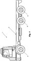
- Figure 1 shows a vehicle (V), such as those used for transporting loads and/or passengers.
- V vehicle
- the new braking system which is the subject of the present invention, may be applied in any type of vehicle, such as a truck, bus, small or large passenger vehicle and even motorcycle, provided that such vehicles use drum-type braking systems.
- the vehicle (V) may consist of at least one main drive assembly (T) comprising a combustion, electric or even hybrid engine as a power source, a gearbox that may be connected to a drive shaft which, in turn, is linked to a differential that transfers energy and power to the wheel assemblies supporting the respective wheel hubs (R).
- T main drive assembly
- R gearbox
- each wheel assembly of said vehicle (V) with its respective wheel hub (R) may comprise a braking system (F), such as the subject of the present invention.
- this vehicle may be a model known in the prior art, such as those manufactured and marketed by CNH Industrial N.V.
- the braking system (F) basically consists of a frame 1 that is fixed at the end of the rigid axle and on which a drum 2 is concentrically placed, which is associated with the wheel hub (R).
- Said frame 1 also known as a mirror or brake plate, is responsible for supporting shoes 3 provided with brake linings 30 which are arranged on portions of diametrically opposite edges of said frame 1, said shoes 3 moving towards the inner surface of said drum 2 by means of a drive assembly 4.
- Said drive assembly 4 comprises two actuators, a first actuator 5a positioned adjacent to one end of said shoes 3, and a second actuator 5b positioned adjacent to the opposite end of said shoes 3, wherein the ends of said shoes 3 are in contact with said respective actuators 5a, 5b through interaction elements 6.
- each of said actuators 5a, 5b is mounted concentrically with respective supports 7a, 7b, which are interconnected by means of rods 8 arranged at their ends so as to provide a coordinated and uniform movement of said shoes 3 with their respective brake linings 30.
- at least one of said actuators 5a, 5b is mechanically coupled to an actuator assembly 9 which is driven according to the demand of the driver of the vehicle (V), for example via the brake pedal or lever.
- said shoes 3 are interconnected by means of return elements 10, such as for example coil springs, the purpose of which is to provide for and facilitate the repositioning of the shoes 3 when the drive assembly 4 is not actuated, and thereby to release the movement of said drum 2 together with the wheel hub.
- return elements 10 such as for example coil springs
- said actuators 5a, 5b comprise an "S" cam configuration, such that said interaction elements 6 slide over the surface of said "S"-shaped cam to thereby promote displacement of said shoes 3.
- said interaction elements 6 slide over the surface of said "S"-shaped cam to thereby promote displacement of said shoes 3.
- the shoes 3 move away from or towards the centre of the frame 1, making or preventing contact of said brake linings 30 with the inner surface of said drum 2.
- said actuators 5a, 5b can be easily implemented according to the teachings of the present invention.
- said actuators may comprise an elliptical cam configuration, or any other equivalent and presenting a shape capable of transferring the movement of the actuator assembly 9 in a coordinated manner so that said shoes 3 move towards the inner surface of the drum 2.
- said interaction elements 6 are, for example, rolling supports or merely bearings capable of promoting a sliding and smooth contact on the surface of the actuators 5a, 5b, that is, such an arrangement facilitates the interaction between the shoes 3 and the respective actuators 5a, 5b, thus reducing any friction that may exist between said actuators and said shoes.
- the actuator assembly 9 used in the braking system (F), according to the present invention may be hydraulic, electric, pneumatic or a combination of these technologies.
- the vehicles may comprise different actuator assemblies, since it directly depends on the configurations and characteristics of each vehicle, for example, trucks and buses often use pneumatic braking mechanisms, whereas conventional vehicles normally comprise hydraulic mechanisms, as well as tractors and other machines that usually carry a hydraulic oil pressurization system for the actuation of various devices and mechanisms.
- the braking system for vehicles comprises a drive assembly 4 consisting of innovative technical and constructive characteristics and capable of promoting the coordinated and uniform displacement of the shoes 3 and, consequently, causing the solid contact of the brake linings 30 with the inner surface of the drum 2 to, in this way, obtain the safest braking, in addition to the comfort and precision of the driver at the time of braking the vehicle.
- the drive assembly 4, according to the present invention does not require substantial adaptations in the structure of the braking system (F) and, in this way, the reduction of costs in relation to the manufacture, assembly and maintenance of the braking systems becomes clear.
- the system is also able to obtain a more uniform wear of the brake linings 30, which causes their service life to increase significantly.
- the new braking system (F), simplifies the process of construction and assembly of braking systems comprising a dual drive configuration, thus enabling significant reductions to be obtained in the costs involved in the production of these systems and also of vehicles in general.
- the present invention deals with a vehicle for transporting loads and/or passengers (V), comprising a main drive assembly (T) consisting of a combustion, electric or even hybrid engine as a power source, a gearbox that is connected in some way to at least one axle capable of transferring energy and power to at least one wheel assembly equipped with a wheel hub (R), where a braking system is mounted on at least one of said wheel assemblies (F), , according to the above embodiments.
- a main drive assembly consisting of a combustion, electric or even hybrid engine as a power source
- a gearbox that is connected in some way to at least one axle capable of transferring energy and power to at least one wheel assembly equipped with a wheel hub (R), where a braking system is mounted on at least one of said wheel assemblies (F), , according to the above embodiments.
- the vehicle for transporting loads and/or passengers may be a truck, bus, van, or even conventional small or large passenger vehicle, including a motorcycle.
Landscapes
- Engineering & Computer Science (AREA)
- General Engineering & Computer Science (AREA)
- Mechanical Engineering (AREA)
- Braking Arrangements (AREA)
Abstract
Description
- The present invention relates, in general, to a novel braking system for vehicles, such as those suitable for transporting loads and/or passengers, that is made up of technical, constructive and functional characteristics designed and developed to improve the working conditions of drivers in traffic, but mainly to increase the efficiency, safety and service life of the braking system. The present invention also relates to vehicles, particularly those suitable for transporting loads and/or passengers.
- According to the prior art, and as is generally known by those skilled in the art, there are already several models of braking systems that are used in practically all vehicles. These systems normally comprise mechanisms designed to generate friction with the moving parts of the wheels in order to decelerate and stop the vehicle. A model commonly used in the prior art, and also known in the market as drum brakes, basically consists of the arrangement of a mechanism fixed to the axle of the vehicle that has shoes connected by return elements that support the brake lining and are driven by an actuator assembly, which pushes said shoes against the drum that, in turn, is fixed to the wheel hub of the vehicle and, thus, it is possible to generate friction causing the deceleration of the wheel.
- In this sense, it is observed that the most traditional and common models of drum braking systems for vehicles are used, according to the state of the art, whose simple construction and functionality could be improved. More particularly, in these models the shoes are actuated by means of only one actuator positioned at one end, while the opposite end is merely pivoted to assist the angular movement of the shoes to enter into contact with the drum that is associated with the wheel hub. In these cases, as it can be observed by those skilled in the art, despite the simplicity, this solution reveals some limitations related to efficiency and safety, because the contact area of the shoes with the drum becomes somewhat irregular considering that the actuators are positioned only at one end, besides providing a reduced contact area, consequently affecting braking efficiency and causing disordered, unbalanced and even premature wear of some components of said braking system.
- In view of these drawbacks, another model of drum braking system has been developed with dual actuation, i.e., in this solution proposed by the prior art, these shoes are driven at both ends, making the contact between the shoes and drum more uniform, in order to try to increase the braking efficiency and the service life of the components of these prior art systems. However, to obtain this drive at both ends, it was considered necessary to add a series of components, such as, for example, complementary actuators for the drive assembly, to restructure the braking system, as well as the actuator system, whether hydraulic, pneumatic or electric, substantially increasing the cost of assembling the braking systems, and the vehicles themselves.
- Additionally, in an attempt to simplify and reduce the costs involved in the assembly of these braking systems with dual actuation, there are some solutions that require transmission elements that take up significant space inside the system and may even require other complementary adaptations in the structure and assembly to accommodate said elements, for example, changing the wheel hub, the drum itself and, consequently, the vehicle characteristics and specifications.
- Therefore, although the known solutions in the state of the art address some needs, it is observed that the drum braking systems, in particular, consist of relatively complex and/or inefficient structural and constructive arrangements that require restructuring the mechanisms, raising the production and assembly costs of these braking systems.
- Thus, considering the above, it is possible to state that the braking systems for vehicles transporting loads and/or passengers available and known in the prior art lack solutions that are effectively simple, but mainly efficient, safe and capable of reducing the costs involved with the manufacture and assembly of the vehicles. These are, therefore, the objectives for the development of the present invention.
- Given the above scenario, it is one of the objectives of the present invention to provide a new braking system for vehicles, which is specially designed and developed to obtain a practical and functional solution to the problems, limitations and drawbacks generated by the braking systems known in the prior art, as exemplified above.
- More particularly, one objective of the present invention is to provide a braking system for vehicles comprising innovative technical, constructive and functional features capable of reducing the complexity of the construction of said systems, particularly of those having double-shoe actuating mechanisms, and thus reducing the costs involved with the manufacture and assembly thereof, as well as of the vehicles themselves.
- Another objective of the present invention is to provide a vehicle for transporting loads and/or passengers that comprises a braking system, as mentioned above.
- Thus, in order to achieve the objectives and technical and functional effects indicated above, among others, the present invention relates to a braking system for a vehicle, which basically consists of a frame fixed to the rigid axle of the vehicle on which a drum is placed, which is connected with the wheel hub, at least two shoes provided with brake linings being arranged on diametrically opposite edges of said frame and moving towards the inner surface of said drum by means of an drive assembly. This system comprises a drive assembly that is made up of a first actuator positioned adjacent to one end of said shoes, and a second actuator positioned adjacent to the opposite end of said shoes, at least one of which is coupled to a actuator assembly of the vehicle. Furthermore, said drive assembly comprises supports that are mounted concentrically with the respective first and second actuators and interconnected by means of rods arranged at the ends thereof.
- According to one embodiment of the present invention, said shoes are interconnected by means of return elements. Furthermore, said shoes can comprise interaction elements at the ends thereof that are in contact with the respective actuators, whereby, according to a particular embodiment, said interaction elements can be rolling supports or bearings that are in sliding contact on the surface of said actuators.
- Additionally, said actuators comprise an "S" cam configuration or, optionally, an elliptical configuration.
- Also, according to possible embodiments of the present invention, said actuator assembly may be of the hydraulic, electric, pneumatic type or a combination of these technologies.
- The present invention also deals with a vehicle for transporting loads and/or passengers, that comprises a main drive assembly consisting of a combustion, electric or even hybrid engine as a power source, a gearbox that is connected to at least one axle capable of transferring energy and power to at least one wheel assembly comprising a tyre and wheel, a braking system as presented above being mounted on at least one of said assemblies.
- According to particular embodiments of the present invention, this vehicle can be, for example, a truck, buses, van, conventional small or large passenger vehicle or motorcycle.
- The characteristics, advantages and technical effects of the present invention, as indicated above, will be more adequately understood by a person skilled in the art from the following detailed description, merely by way of non-limiting example, of possible embodiments, and with reference to the attached schematic figures, namely:
-
Figure 1 shows a schematic side view of an example vehicle, such as a commercial van for the transport of loads and/or passengers; and -
Figure 2 shows a schematic side view of the braking system for vehicles according to the present invention. - The invention is now described with respect to its particular embodiments by referring to the attached figures showing examples thereof. Such figures are schematic, and their dimensions and/or proportions may not correspond to reality, since they are intended to describe the invention in a didactic manner. The reference numbers indicated in said figures may be repeated across the different figures to indicate equal or similar technical characteristics. Furthermore, the terms eventually used herein such as: above, below, superior, inferior, lateral, right, left, frontal, posterior and its variants should be interpreted according to the guidelines given in
Figure 1 . - Merely by way of example, and for a better understanding of the present invention,
Figure 1 shows a vehicle (V), such as those used for transporting loads and/or passengers. It should be noted that althoughFigure 1 shows a van, to be appreciated by those skilled in the art, the new braking system, which is the subject of the present invention, may be applied in any type of vehicle, such as a truck, bus, small or large passenger vehicle and even motorcycle, provided that such vehicles use drum-type braking systems. In this context, the vehicle (V) may consist of at least one main drive assembly (T) comprising a combustion, electric or even hybrid engine as a power source, a gearbox that may be connected to a drive shaft which, in turn, is linked to a differential that transfers energy and power to the wheel assemblies supporting the respective wheel hubs (R). As shall be appreciated by those skilled in the art, each wheel assembly of said vehicle (V) with its respective wheel hub (R) may comprise a braking system (F), such as the subject of the present invention. - Thus, only as an example, and without limitations, this vehicle (V) may be a model known in the prior art, such as those manufactured and marketed by CNH Industrial N.V.
- In this context, according to the scope of the present invention, the braking system (F) basically consists of a
frame 1 that is fixed at the end of the rigid axle and on which adrum 2 is concentrically placed, which is associated with the wheel hub (R). Saidframe 1, also known as a mirror or brake plate, is responsible for supportingshoes 3 provided withbrake linings 30 which are arranged on portions of diametrically opposite edges of saidframe 1, saidshoes 3 moving towards the inner surface of saiddrum 2 by means of adrive assembly 4. - Said
drive assembly 4 according to the present invention comprises two actuators, a first actuator 5a positioned adjacent to one end of saidshoes 3, and asecond actuator 5b positioned adjacent to the opposite end of saidshoes 3, wherein the ends of saidshoes 3 are in contact with saidrespective actuators 5a, 5b throughinteraction elements 6. Also, each of saidactuators 5a, 5b is mounted concentrically withrespective supports rods 8 arranged at their ends so as to provide a coordinated and uniform movement of saidshoes 3 with theirrespective brake linings 30. Also, according to the present invention, at least one of saidactuators 5a, 5b is mechanically coupled to an actuator assembly 9 which is driven according to the demand of the driver of the vehicle (V), for example via the brake pedal or lever. - According to a particular embodiment of the present invention, said
shoes 3 are interconnected by means ofreturn elements 10, such as for example coil springs, the purpose of which is to provide for and facilitate the repositioning of theshoes 3 when thedrive assembly 4 is not actuated, and thereby to release the movement of saiddrum 2 together with the wheel hub. - Additionally, according to one embodiment of the present invention, said
actuators 5a, 5b comprise an "S" cam configuration, such that saidinteraction elements 6 slide over the surface of said "S"-shaped cam to thereby promote displacement of saidshoes 3. As may be appreciated by those skilled in the art, considering the "S" silhouette of the cam, as theinteraction elements 6 move on theactuators 5a, 5b, theshoes 3 move away from or towards the centre of theframe 1, making or preventing contact of saidbrake linings 30 with the inner surface of saiddrum 2. - As should be appreciated by those skilled in the art, other cam configurations for the
actuators 5a, 5b can be easily implemented according to the teachings of the present invention. By way of example, said actuators may comprise an elliptical cam configuration, or any other equivalent and presenting a shape capable of transferring the movement of the actuator assembly 9 in a coordinated manner so that saidshoes 3 move towards the inner surface of thedrum 2. - As a further embodiment of the present invention, said
interaction elements 6 are, for example, rolling supports or merely bearings capable of promoting a sliding and smooth contact on the surface of theactuators 5a, 5b, that is, such an arrangement facilitates the interaction between theshoes 3 and therespective actuators 5a, 5b, thus reducing any friction that may exist between said actuators and said shoes. - Additionally, as should be known to those skilled in the art, the actuator assembly 9 used in the braking system (F), according to the present invention, may be hydraulic, electric, pneumatic or a combination of these technologies. This is because it is known that the vehicles may comprise different actuator assemblies, since it directly depends on the configurations and characteristics of each vehicle, for example, trucks and buses often use pneumatic braking mechanisms, whereas conventional vehicles normally comprise hydraulic mechanisms, as well as tractors and other machines that usually carry a hydraulic oil pressurization system for the actuation of various devices and mechanisms. And nowadays, there are many models that also use electrical components as actuators for their braking systems. As should be noted, regardless of the type of the actuator assembly 9, what is relevant is that it is able to move one of said
actuators 5a, 5b and, as a consequence of the construction and assembly of the present system, to move the other actuator through the interconnection obtained by therods 8. - Thus, as can be seen, the braking system for vehicles, the subject of the present invention, comprises a
drive assembly 4 consisting of innovative technical and constructive characteristics and capable of promoting the coordinated and uniform displacement of theshoes 3 and, consequently, causing the solid contact of thebrake linings 30 with the inner surface of thedrum 2 to, in this way, obtain the safest braking, in addition to the comfort and precision of the driver at the time of braking the vehicle. It should be noted that thedrive assembly 4, according to the present invention, does not require substantial adaptations in the structure of the braking system (F) and, in this way, the reduction of costs in relation to the manufacture, assembly and maintenance of the braking systems becomes clear. The system is also able to obtain a more uniform wear of thebrake linings 30, which causes their service life to increase significantly. - Thus, in summary, it can be stated that the new braking system (F), , according to the present invention and detailed above, simplifies the process of construction and assembly of braking systems comprising a dual drive configuration, thus enabling significant reductions to be obtained in the costs involved in the production of these systems and also of vehicles in general.
- Additionally, as commented above, the present invention deals with a vehicle for transporting loads and/or passengers (V), comprising a main drive assembly (T) consisting of a combustion, electric or even hybrid engine as a power source, a gearbox that is connected in some way to at least one axle capable of transferring energy and power to at least one wheel assembly equipped with a wheel hub (R), where a braking system is mounted on at least one of said wheel assemblies (F), , according to the above embodiments.
- More particularly, according to possible embodiments of the present invention, the vehicle for transporting loads and/or passengers (V) may be a truck, bus, van, or even conventional small or large passenger vehicle, including a motorcycle.
- Finally, in view of all the above, it is important to be clear that the present description has as its only objective to present and define, in an exemplifying manner, embodiments of the braking system for vehicles for transporting loads and/or passengers, according to the present invention. Therefore, as the persons skilled in the art should understand, several modifications and constructive combinations of equivalent elements are possible without, therefore, departing from the scope of protection defined by the attached claims.
Claims (8)
- A BRAKING SYSTEM FOR A VEHICLE, which consists of a frame (1) fixed to the rigid axle of the vehicle (V), and which is superimposed by a drum (2), which is connected to the wheel hub (R), wherein at least two shoes (3) provided with brake linings (30) are arranged at diametrically opposite edges of said frame (1) and move towards the inner surface of said drum (2) by means of a drive assembly (4), wherein the system is characterised by the fact that said drive assembly (4) comprises:a first actuator (5a) positioned adjacent to one end of said shoes (3), and a second actuator (5b) positioned adjacent to the opposite end of said shoes (3), at least one of which is coupled to an actuator assembly (9) of the vehicle (V); andsupports (7a, 7b) mounted concentrically with the respective actuators (5a, 5b) and which are interconnected by means of rods (8) arranged at their ends.
- THE SYSTEM, according to claim 1, characterised in that said shoes (3) are interconnected by means of return elements (10).
- THE SYSTEM, according to claim 1, characterised in that said actuators (5a, 5b) comprise an "S" or elliptical cam configuration.
- THE SYSTEM, according to claim 1, characterised in that said shoes (3) comprise interaction elements (6) at their ends which are in contact with the respective actuators (5a, 5b).
- THE SYSTEM, according to claim 1, characterised in that said interaction elements (6) are rolling supports or bearings which are in sliding contact? on the surface of said actuators (5a, 5b).
- THE SYSTEM, according to claim 1, characterised in that said actuator assembly (9) is hydraulic, electric, pneumatic or a combination of these technologies.
- A VEHICLE FOR TRANSPORTING LOADS AND/OR PASSENGERS that comprises a main drive assembly (T) consisting of a combustion, electric or even hybrid engine as a power source, a gearbox which is connected to at least one axle capable of transferring energy and power to at least one drive assembly with a (R), said vehicle (V) characterised in that a braking system (F) is mounted on at least one of said wheel hubs (R), as defined in any one of the preceding claims.
- THE VEHICLE, according to claim 6, characterised in that it is a truck, bus, van, conventional small or large passenger vehicle or motorcycle.
Applications Claiming Priority (2)
| Application Number | Priority Date | Filing Date | Title |
|---|---|---|---|
| BR102019018156-7A BR102019018156B1 (en) | 2019-08-30 | Braking system for a vehicle and vehicle for transporting cargo and/or passengers. | |
| PCT/BR2020/050335 WO2021035321A1 (en) | 2019-08-30 | 2020-08-24 | Braking system for a vehicle and vehicle for transporting loads and/or passengers |
Publications (4)
| Publication Number | Publication Date |
|---|---|
| EP4023901A1 true EP4023901A1 (en) | 2022-07-06 |
| EP4023901A4 EP4023901A4 (en) | 2023-11-08 |
| EP4023901C0 EP4023901C0 (en) | 2025-08-06 |
| EP4023901B1 EP4023901B1 (en) | 2025-08-06 |
Family
ID=74683731
Family Applications (1)
| Application Number | Title | Priority Date | Filing Date |
|---|---|---|---|
| EP20856267.8A Active EP4023901B1 (en) | 2019-08-30 | 2020-08-24 | Braking system for a vehicle and vehicle for transporting loads and/or passengers |
Country Status (2)
| Country | Link |
|---|---|
| EP (1) | EP4023901B1 (en) |
| WO (1) | WO2021035321A1 (en) |
Family Cites Families (7)
| Publication number | Priority date | Publication date | Assignee | Title |
|---|---|---|---|---|
| GB191015412A (en) * | 1910-06-27 | 1911-06-27 | Werner Anton Trier | Improvements in or relating to Brakes for Motor Road Vehicles. |
| GB221635A (en) * | 1923-08-23 | 1924-09-18 | William Somerville Renwick | Improvements in brakes preferably for use on motor vehicles |
| US1735507A (en) * | 1924-01-23 | 1929-11-12 | Cie Applic Mecaniques | Brake for motor-vehicle wheels |
| US5310028A (en) * | 1992-12-15 | 1994-05-10 | Eaton Corporation | S-cam for drum brake |
| US9512891B2 (en) * | 2014-11-01 | 2016-12-06 | Bendix Spicer Foundation Brake Llc | Brake shoe for drum brake having offset cam followers |
| US9428157B2 (en) * | 2014-11-01 | 2016-08-30 | Bendix Spicer Foundation Brake Llc | Drum brake S-cam having offset cam followers |
| CN109982884B (en) * | 2016-12-14 | 2022-06-03 | 依维柯股份有限公司 | Power transmission assembly for tandem axle |
-
2020
- 2020-08-24 EP EP20856267.8A patent/EP4023901B1/en active Active
- 2020-08-24 WO PCT/BR2020/050335 patent/WO2021035321A1/en not_active Ceased
Also Published As
| Publication number | Publication date |
|---|---|
| EP4023901C0 (en) | 2025-08-06 |
| BR102019018156A2 (en) | 2021-03-16 |
| EP4023901A4 (en) | 2023-11-08 |
| EP4023901B1 (en) | 2025-08-06 |
| WO2021035321A1 (en) | 2021-03-04 |
Similar Documents
| Publication | Publication Date | Title |
|---|---|---|
| US6367571B1 (en) | Drive wheel system for industrial trucks | |
| CN113306541B (en) | Safety system for an electrically drivable vehicle, method for operating such a safety system and vehicle | |
| AT520430B1 (en) | Vehicle with an electric drive | |
| WO2016064980A1 (en) | Electric parking brake having twin independent actuators | |
| US8056684B2 (en) | Vehicle drum-in-hat disc brake assembly and method for producing same | |
| CN119317559A (en) | Powertrain for electric vehicle and electric vehicle | |
| MX2008014714A (en) | Lever system for actuating a clutch. | |
| US20190291797A1 (en) | Customizable chassis module with integrated related functions | |
| EP4023901B1 (en) | Braking system for a vehicle and vehicle for transporting loads and/or passengers | |
| CN201095358Y (en) | Disconnecting wheel edge deceleration driving axle assembling disc type brake | |
| CA3108976C (en) | Vehicle with front-wheel-assist system | |
| CN101186183B (en) | Electric eddy speed damper | |
| CN201058612Y (en) | Railway automatic hump target shooting braking emergency crash-proof vehicle retarder | |
| JP5211763B2 (en) | Drive axle device for industrial vehicles | |
| CN201566689U (en) | Oil brake pipe type large-drop front axle | |
| EP3589507A1 (en) | Customizable chassis module with integrated related functions | |
| CN2140326Y (en) | Drum type hand brake | |
| BR102019018156B1 (en) | Braking system for a vehicle and vehicle for transporting cargo and/or passengers. | |
| EP4219976A1 (en) | Park brake caliper with inverted lever configuration | |
| CN222836244U (en) | A mid-bridge reducer structure assembly with double-caliper parking brake | |
| EP4310359A1 (en) | Braking system and braking system provision method | |
| CN119953106A (en) | A hybrid drive rear axle structure | |
| CN223890719U (en) | Driving axle assembly and vehicle with same | |
| CN220298226U (en) | Driving axle of structural type carrier | |
| CZ2024316A3 (en) | An additional parking brake, a method of its operation and a vehicle containing such brake |
Legal Events
| Date | Code | Title | Description |
|---|---|---|---|
| STAA | Information on the status of an ep patent application or granted ep patent |
Free format text: STATUS: THE INTERNATIONAL PUBLICATION HAS BEEN MADE |
|
| PUAI | Public reference made under article 153(3) epc to a published international application that has entered the european phase |
Free format text: ORIGINAL CODE: 0009012 |
|
| STAA | Information on the status of an ep patent application or granted ep patent |
Free format text: STATUS: REQUEST FOR EXAMINATION WAS MADE |
|
| 17P | Request for examination filed |
Effective date: 20220224 |
|
| AK | Designated contracting states |
Kind code of ref document: A1 Designated state(s): AL AT BE BG CH CY CZ DE DK EE ES FI FR GB GR HR HU IE IS IT LI LT LU LV MC MK MT NL NO PL PT RO RS SE SI SK SM TR |
|
| DAV | Request for validation of the european patent (deleted) | ||
| DAX | Request for extension of the european patent (deleted) | ||
| RIN1 | Information on inventor provided before grant (corrected) |
Inventor name: PEREIRA DE LEMOS, JOSE FRANCIVALDO |
|
| A4 | Supplementary search report drawn up and despatched |
Effective date: 20231006 |
|
| RIC1 | Information provided on ipc code assigned before grant |
Ipc: F16D 51/22 20060101ALI20230929BHEP Ipc: F16D 51/20 20060101ALI20230929BHEP Ipc: F16D 51/18 20060101ALI20230929BHEP Ipc: F16D 51/10 20060101AFI20230929BHEP |
|
| GRAP | Despatch of communication of intention to grant a patent |
Free format text: ORIGINAL CODE: EPIDOSNIGR1 |
|
| STAA | Information on the status of an ep patent application or granted ep patent |
Free format text: STATUS: GRANT OF PATENT IS INTENDED |
|
| INTG | Intention to grant announced |
Effective date: 20250312 |
|
| GRAS | Grant fee paid |
Free format text: ORIGINAL CODE: EPIDOSNIGR3 |
|
| GRAA | (expected) grant |
Free format text: ORIGINAL CODE: 0009210 |
|
| STAA | Information on the status of an ep patent application or granted ep patent |
Free format text: STATUS: THE PATENT HAS BEEN GRANTED |
|
| AK | Designated contracting states |
Kind code of ref document: B1 Designated state(s): AL AT BE BG CH CY CZ DE DK EE ES FI FR GB GR HR HU IE IS IT LI LT LU LV MC MK MT NL NO PL PT RO RS SE SI SK SM TR |
|
| REG | Reference to a national code |
Ref country code: GB Ref legal event code: FG4D |
|
| REG | Reference to a national code |
Ref country code: CH Ref legal event code: EP |
|
| REG | Reference to a national code |
Ref country code: IE Ref legal event code: FG4D |
|
| REG | Reference to a national code |
Ref country code: DE Ref legal event code: R096 Ref document number: 602020056164 Country of ref document: DE |
|
| U01 | Request for unitary effect filed |
Effective date: 20250806 |
|
| U07 | Unitary effect registered |
Designated state(s): AT BE BG DE DK EE FI FR IT LT LU LV MT NL PT RO SE SI Effective date: 20250818 |
|
| U20 | Renewal fee for the european patent with unitary effect paid |
Year of fee payment: 6 Effective date: 20250812 |
|
| PG25 | Lapsed in a contracting state [announced via postgrant information from national office to epo] |
Ref country code: IS Free format text: LAPSE BECAUSE OF FAILURE TO SUBMIT A TRANSLATION OF THE DESCRIPTION OR TO PAY THE FEE WITHIN THE PRESCRIBED TIME-LIMIT Effective date: 20251206 |
|
| PG25 | Lapsed in a contracting state [announced via postgrant information from national office to epo] |
Ref country code: NO Free format text: LAPSE BECAUSE OF FAILURE TO SUBMIT A TRANSLATION OF THE DESCRIPTION OR TO PAY THE FEE WITHIN THE PRESCRIBED TIME-LIMIT Effective date: 20251106 |
|
| PG25 | Lapsed in a contracting state [announced via postgrant information from national office to epo] |
Ref country code: HR Free format text: LAPSE BECAUSE OF FAILURE TO SUBMIT A TRANSLATION OF THE DESCRIPTION OR TO PAY THE FEE WITHIN THE PRESCRIBED TIME-LIMIT Effective date: 20250806 |
|
| PG25 | Lapsed in a contracting state [announced via postgrant information from national office to epo] |
Ref country code: GR Free format text: LAPSE BECAUSE OF FAILURE TO SUBMIT A TRANSLATION OF THE DESCRIPTION OR TO PAY THE FEE WITHIN THE PRESCRIBED TIME-LIMIT Effective date: 20251107 |
|
| PG25 | Lapsed in a contracting state [announced via postgrant information from national office to epo] |
Ref country code: PL Free format text: LAPSE BECAUSE OF FAILURE TO SUBMIT A TRANSLATION OF THE DESCRIPTION OR TO PAY THE FEE WITHIN THE PRESCRIBED TIME-LIMIT Effective date: 20250806 |
|
| PG25 | Lapsed in a contracting state [announced via postgrant information from national office to epo] |
Ref country code: RS Free format text: LAPSE BECAUSE OF FAILURE TO SUBMIT A TRANSLATION OF THE DESCRIPTION OR TO PAY THE FEE WITHIN THE PRESCRIBED TIME-LIMIT Effective date: 20251106 |
|
| PG25 | Lapsed in a contracting state [announced via postgrant information from national office to epo] |
Ref country code: ES Free format text: LAPSE BECAUSE OF FAILURE TO SUBMIT A TRANSLATION OF THE DESCRIPTION OR TO PAY THE FEE WITHIN THE PRESCRIBED TIME-LIMIT Effective date: 20250806 |
|
| REG | Reference to a national code |
Ref country code: CH Ref legal event code: H13 Free format text: ST27 STATUS EVENT CODE: U-0-0-H10-H13 (AS PROVIDED BY THE NATIONAL OFFICE) Effective date: 20260324 |
|
| PG25 | Lapsed in a contracting state [announced via postgrant information from national office to epo] |
Ref country code: SM Free format text: LAPSE BECAUSE OF FAILURE TO SUBMIT A TRANSLATION OF THE DESCRIPTION OR TO PAY THE FEE WITHIN THE PRESCRIBED TIME-LIMIT Effective date: 20250806 |
|
| PG25 | Lapsed in a contracting state [announced via postgrant information from national office to epo] |
Ref country code: CZ Free format text: LAPSE BECAUSE OF FAILURE TO SUBMIT A TRANSLATION OF THE DESCRIPTION OR TO PAY THE FEE WITHIN THE PRESCRIBED TIME-LIMIT Effective date: 20250806 Ref country code: CH Free format text: LAPSE BECAUSE OF NON-PAYMENT OF DUE FEES Effective date: 20250831 |
|
| PG25 | Lapsed in a contracting state [announced via postgrant information from national office to epo] |
Ref country code: SK Free format text: LAPSE BECAUSE OF FAILURE TO SUBMIT A TRANSLATION OF THE DESCRIPTION OR TO PAY THE FEE WITHIN THE PRESCRIBED TIME-LIMIT Effective date: 20250806 |